EP3103916B1 - Refiner beating method and refiner - Google Patents
Refiner beating method and refiner Download PDFInfo
- Publication number
- EP3103916B1 EP3103916B1 EP16173778.8A EP16173778A EP3103916B1 EP 3103916 B1 EP3103916 B1 EP 3103916B1 EP 16173778 A EP16173778 A EP 16173778A EP 3103916 B1 EP3103916 B1 EP 3103916B1
- Authority
- EP
- European Patent Office
- Prior art keywords
- rotor
- beating portion
- raw material
- stator
- beating
- Prior art date
- Legal status (The legal status is an assumption and is not a legal conclusion. Google has not performed a legal analysis and makes no representation as to the accuracy of the status listed.)
- Not-in-force
Links
- 238000010009 beating Methods 0.000 title claims description 726
- 238000000034 method Methods 0.000 title claims description 21
- 239000002994 raw material Substances 0.000 claims description 328
- 230000000149 penetrating effect Effects 0.000 claims description 40
- 238000013459 approach Methods 0.000 claims description 18
- 238000007599 discharging Methods 0.000 claims description 5
- 238000007670 refining Methods 0.000 description 11
- 239000000463 material Substances 0.000 description 3
- 238000003466 welding Methods 0.000 description 2
- 230000007423 decrease Effects 0.000 description 1
- 230000000694 effects Effects 0.000 description 1
- 238000004134 energy conservation Methods 0.000 description 1
- 239000002657 fibrous material Substances 0.000 description 1
- 239000000725 suspension Substances 0.000 description 1
Images










Classifications
-
- D—TEXTILES; PAPER
- D21—PAPER-MAKING; PRODUCTION OF CELLULOSE
- D21D—TREATMENT OF THE MATERIALS BEFORE PASSING TO THE PAPER-MAKING MACHINE
- D21D1/00—Methods of beating or refining; Beaters of the Hollander type
- D21D1/02—Methods of beating; Beaters of the Hollander type
-
- D—TEXTILES; PAPER
- D21—PAPER-MAKING; PRODUCTION OF CELLULOSE
- D21D—TREATMENT OF THE MATERIALS BEFORE PASSING TO THE PAPER-MAKING MACHINE
- D21D1/00—Methods of beating or refining; Beaters of the Hollander type
- D21D1/20—Methods of refining
- D21D1/22—Jordans
-
- B—PERFORMING OPERATIONS; TRANSPORTING
- B02—CRUSHING, PULVERISING, OR DISINTEGRATING; PREPARATORY TREATMENT OF GRAIN FOR MILLING
- B02C—CRUSHING, PULVERISING, OR DISINTEGRATING IN GENERAL; MILLING GRAIN
- B02C7/00—Crushing or disintegrating by disc mills
-
- B—PERFORMING OPERATIONS; TRANSPORTING
- B02—CRUSHING, PULVERISING, OR DISINTEGRATING; PREPARATORY TREATMENT OF GRAIN FOR MILLING
- B02C—CRUSHING, PULVERISING, OR DISINTEGRATING IN GENERAL; MILLING GRAIN
- B02C7/00—Crushing or disintegrating by disc mills
- B02C7/02—Crushing or disintegrating by disc mills with coaxial discs
-
- B—PERFORMING OPERATIONS; TRANSPORTING
- B02—CRUSHING, PULVERISING, OR DISINTEGRATING; PREPARATORY TREATMENT OF GRAIN FOR MILLING
- B02C—CRUSHING, PULVERISING, OR DISINTEGRATING IN GENERAL; MILLING GRAIN
- B02C7/00—Crushing or disintegrating by disc mills
- B02C7/11—Details
- B02C7/12—Shape or construction of discs
-
- D—TEXTILES; PAPER
- D21—PAPER-MAKING; PRODUCTION OF CELLULOSE
- D21D—TREATMENT OF THE MATERIALS BEFORE PASSING TO THE PAPER-MAKING MACHINE
- D21D1/00—Methods of beating or refining; Beaters of the Hollander type
- D21D1/02—Methods of beating; Beaters of the Hollander type
- D21D1/04—Beater rolls or bars
-
- D—TEXTILES; PAPER
- D21—PAPER-MAKING; PRODUCTION OF CELLULOSE
- D21D—TREATMENT OF THE MATERIALS BEFORE PASSING TO THE PAPER-MAKING MACHINE
- D21D1/00—Methods of beating or refining; Beaters of the Hollander type
- D21D1/02—Methods of beating; Beaters of the Hollander type
- D21D1/06—Bed plates
-
- D—TEXTILES; PAPER
- D21—PAPER-MAKING; PRODUCTION OF CELLULOSE
- D21D—TREATMENT OF THE MATERIALS BEFORE PASSING TO THE PAPER-MAKING MACHINE
- D21D1/00—Methods of beating or refining; Beaters of the Hollander type
- D21D1/20—Methods of refining
- D21D1/22—Jordans
- D21D1/26—Jordan bed plates
-
- D—TEXTILES; PAPER
- D21—PAPER-MAKING; PRODUCTION OF CELLULOSE
- D21D—TREATMENT OF THE MATERIALS BEFORE PASSING TO THE PAPER-MAKING MACHINE
- D21D1/00—Methods of beating or refining; Beaters of the Hollander type
- D21D1/20—Methods of refining
- D21D1/30—Disc mills
-
- D—TEXTILES; PAPER
- D21—PAPER-MAKING; PRODUCTION OF CELLULOSE
- D21D—TREATMENT OF THE MATERIALS BEFORE PASSING TO THE PAPER-MAKING MACHINE
- D21D1/00—Methods of beating or refining; Beaters of the Hollander type
- D21D1/20—Methods of refining
- D21D1/30—Disc mills
- D21D1/303—Double disc mills
-
- D—TEXTILES; PAPER
- D21—PAPER-MAKING; PRODUCTION OF CELLULOSE
- D21D—TREATMENT OF THE MATERIALS BEFORE PASSING TO THE PAPER-MAKING MACHINE
- D21D1/00—Methods of beating or refining; Beaters of the Hollander type
- D21D1/20—Methods of refining
- D21D1/30—Disc mills
- D21D1/306—Discs
Definitions
- the present invention relates to a refiner beating method and a refiner and particularly to a refiner beating method and a refiner causing an increase in processing capability.
- a refiner is known as a device for beating pulp (for example, see JP 4518711 B2 ).
- a raw material is beaten by a rotor blade and a stator blade.
- WO 2009/153412 A1 discloses a refiner for refining fibrous material comprising at least one refining surface and at least one second refining surface, which are arranged at least partly substantially opposite to one another in such a manner that a refiner chamber is formed between them, to which the material to be defibrated is arranged to be fed. At least either the first refining surface or the second refining surface in the refiner is arranged such that it can be moved by a rotor with respect to the opposite refining surface. At least either the first refining surface or the second refining surface in the refiner comprises blade bars and blade grooves.
- WO 2012/101330 A1 discloses a conical refiner and a beating method, the refiner having a main body and a rotation shaft provided inside the main body, a perforated rotor and stator of mountain shape in which the centre is high, the rotor having first and second opening portions, both ends of which are open, and a space therein, the stator provided in the main body to oppose the rotor, a rotor beating portion having a groove between the bars, and a stator beating portion.
- the invention is made in view of the above-described circumstances and an object of the invention is to provide a refiner beating method and a refiner causing an increase in processing capability.
- a refiner comprises a main body, a rotation shaft provided inside the main body, a rotor attached to the rotation shaft and having a mountain shape in which a center is high, the rotor having first and second opening portions, both ends of which are open, and a space therein, a stator provided in the main body to oppose the rotor, a rotor beating portion provided on a surface of the rotor except for a center of the rotor in a longitudinal direction, the rotor beating portion having a groove between a bar and a bar and having a plurality of through-holes penetrating therethrough, a stator beating portion provided on a surface of the stator, the stator beating portion opposing the rotor beating portion, and having a groove between a bar and a bar and a plurality of through-holes penetrating therethrough, a first raw material supply portion for supplying a raw material from a side of the first opening portion, the first raw material supply portion being provided in the main body and
- the rotor beating portion includes a first rotor beating portion provided on a surface thereof and a second rotor beating portion provided on the surface, the first rotor beating portion having a first groove between a first bar and a first bar and a plurality of first through-holes penetrating therethrough, the second rotor beating portion having a second groove between a second bar and a second bar and a plurality of second through-holes penetrating therethrough.
- the first bar of the first rotor beating portion is configured, namely inclined, to guide a raw material from a small diameter side of the rotor to a large diameter side of the rotor or to guide a raw material from a large diameter side of the rotor to a small diameter side of the rotor.
- the second bar of the second rotor beating portion is configured, namely inclined, to guide a raw material from a small diameter side of the rotor to a large diameter side of the rotor or to guide a raw material from a large diameter side of the rotor to a small diameter side of the rotor.
- the first raw material supply portion approaches end portions of the first stator beating portion and the first rotor beating portion on a side close to the first raw material supply portion and the first opening portion, end portions of the first stator beating portion and the first rotor beating portion on the large diameter side face the central opening portion, end portions of the second stator beating portion and the second rotor beating portion on the large diameter side face the central opening portion.
- the plurality of through-holes of the first stator beating portion, the plurality of second through-holes of the second stator beating portion, and the central opening portion communicate with the raw material discharge portion.
- a portion of a raw material guided to the first opening portion of the rotor and the space of the rotor is beaten by passing through the plurality of first through-holes of the first rotor beating portion and the plurality of first through-holes of the first stator beating portion, and is discharged to an outside of the first stator beating portion from the plurality of first through-holes of the first stator beating portion.
- a portion of a raw material guided to the space of the rotor is beaten by passing through the plurality of second through-holes of the second rotor beating portion and the plurality of second through-holes of the second stator beating portion, and is discharged to an outside of the second stator beating portion from the plurality of second through-holes of the second stator beating portion.
- a portion of a raw material guided to the first opening portion of the rotor and the space of the rotor passes through the plurality of first through-holes of the first rotor beating portion on a side close to the large diameter side of the rotor, is beaten by passing through a gap between the first stator beating portion and the first rotor beating portion, and is discharged to an outside of the first stator beating portion and the first rotor beating portion through the central opening portion from end portions of the first stator beating portion and the first rotor beating portion on the large diameter side.
- a portion of a raw material guided to the space of the rotor passes through the plurality of second through-holes of the second rotor beating portion on a side close to the large diameter side of the rotor is beaten by passing through a gap between the second stator beating portion and the second rotor beating portion, and is discharged to an outside of the second stator beating portion and the second rotor beating portion through the central opening portion from end portions of the second stator beating portion and the second rotor beating portion on the large diameter side.
- a raw material guided to between the first stator beating portion and the first rotor beating portion on the small diameter side corresponding to the end portions on the side close to the first raw material supply portion is beaten by passing through the first stator beating portion and the first rotor beating portion, and is discharged to an outside of the first stator beating portion through the plurality of first through-holes of the first stator beating portion.
- a portion of a raw material guided to between the second stator beating portion and the second rotor beating portion on the small diameter side corresponding to end portions on a side close to the inner wall of the main body opposing the second opening portion is beaten by passing through the second stator beating portion and the second rotor beating portion, and is discharged to an outside of the second stator beating portion from the plurality of second through-holes of the second stator beating portion.
- R indicates a refiner
- the refiner R has a configuration in which a rotation shaft 2 is provided inside a main body 1.
- a tapered rotor 3 having a space 3K therein is attached to the rotation shaft 2.
- the rotor 3 has a configuration in which a small diameter side serves as a small-diameter opening portion 1H and a large diameter side is blocked.
- a rotor beating portion 31 has a configuration in which a plurality of bars (blades) B1 is provided on a surface of the rotor 3, a groove M1 is provided between a bar (blade) B1 and a bar (blade) B1, and a plurality of through-holes H1 is provided so as to penetrate the rotor 3.
- a bar locking portion (not illustrated) provided in the bar B1 is locked to a bar locked portion (not illustrated) provided in the rotor beating portion 31, the bar B1 is provided across the through-hole H1, and the bar locking portion (not illustrated) locked to the bar locked portion (not illustrated) is fixed by welding or the like.
- the through-hole H1 may have a circular shape ( FIGS. 2 and 3 ) or a rectangular shape.
- the shape is not limited.
- the bar B1 of the rotor beating portion 31 is inclined so as to guide a raw material from the small diameter side of the rotor 3 to the large diameter side of the rotor 3.
- the bar B1 of the rotor beating portion 31 is inclined (an angle A of FIG. 7 is about 5° to about 30°) such that a rear end N of the bar B1 moves with respect to a front end M of the bar B1 in a rotation direction of the rotor 3 (for example, a counterclockwise direction P' illustrated in FIG. 7 and FIG. 8 ) in plan view in which a deep side of the rotor beating portion 31 is positioned at a large diameter of the rotor 3 and a near side of the rotor beating portion 31 is positioned at a small diameter of the rotor 3 (see FIG.
- FIG. 9 and FIG. 10 illustrate a case in which the rotation direction of the rotor 3 is set to a clockwise direction P.
- a stator 4 is provided in the main body 1 to oppose the rotor 3 described above.
- a stator beating portion 41 opposes the rotor beating portion 31, and has a plurality of bars (blades) B1' provided on a surface of the stator 4, a groove M1' provided between a bar (blade) B1' and a bar (blade) B1', and a plurality of through-holes H1' provided so as to penetrate the stator 4.
- a bar locking portion (not illustrated) provided in the bar B1' is locked to a bar locked portion (not illustrated) provided in the stator beating portion 41, the bar B1' is provided across the through-hole H1', and the bar locking portion (not illustrated) locked to the bar locked portion (not illustrated) is fixed by welding or the like.
- the through-hole H1' may have a circular shape ( FIGS. 4 and 5 ) or a rectangular shape.
- the shape is not limited.
- Reference numeral 11 illustrated in FIG. 1 denotes a raw material supply portion.
- the raw material supply portion 11 supplies the raw material (fibrous raw material) into the main body 1, and the raw material supply portion 11 supplies the raw material from a side of the opening portion 1H.
- the raw material from the raw material supply portion 11 is configured to approach end portions X of the stator beating portion 41 and the rotor beating portion 31 on a side closed to the raw material supply portion 11, and the small-diameter opening portion 1H of the rotor.
- reference numeral 5 illustrated in FIG. 1 denotes a raw material discharge portion that discharges the raw material beaten inside the main body 1 to the outside of the main body 1, and the plurality of through-holes H1' of the stator beating portion 41 and end portions Y of the stator beating portion 41 and the rotor beating portion 31 on a side far from the raw material supply portion 11 communicate with the raw material discharge portion 5.
- the raw material into the main body 1 is supplied from the raw material supply portion 11.
- a portion of the raw material supplied from the raw material supply portion 11 is guided into the rotor 3 through the small-diameter opening portion 1H, and another portion of the raw material is guided to between the stator beating portion 41 and the rotor beating portion 31.
- a portion of the raw material guided to the small-diameter opening portion 1H of the rotor 3 and the space 3K of the rotor 3 are beaten by passing through the plurality of through-holes H1 of the rotor beating portion 31 and the plurality of through-holes H1' of the stator beating portion 41, and are discharged to the outside of the stator beating portion 41 from the plurality of through-holes H1' of the stator beating portion 41 (see a flow of arrows a to a' illustrated in FIG. 6 )
- the raw material guided to between the stator beating portion 41 and the rotor beating portion 31 on the small diameter side corresponding to the end portions X on the side closed to the raw material supply portion 11 is beaten by passing through the stator beating portion 41 and the rotor beating portion 31, and is discharged to the outside of the stator beating portion 41 from the plurality of through-holes H1' of the stator beating portion 41 (see a flow of arrows c to c' illustrated in FIG. 6 )
- the raw material beaten by passing through the plurality of through-holes H1 of the rotor beating portion 31 and the plurality of through-holes H1' of the stator beating portion 41 is discharged to the outside of the stator beating portion 41 from the plurality of through-holes H1' of the stator beating portion 41, the raw material passing through the plurality of through-holes H1 of the rotor beating portion 31 on the side close to the large diameter side of the rotor 3 and beaten by passing through a gap between the stator beating portion 41 and the rotor beating portion 31 is discharged to the outside of the stator beating portion 41 and the rotor beating portion 31 from the end portions Y of the stator beating portion 41 and the rotor beating portion 31 on the side far from the raw material supply portion 11, and the raw material guided to between the stator beating portion 41 and the rotor beating portion 31 on the small diameter side corresponding to the end portions X on the side closed to the raw
- the diameter may be made small to be D 2 > D 1 .
- non-load power of the refiner R may be made small, and energy conservation may be attempted.
- non-load power refers to power consumed when the rotor and the stator are open, and the rotor is rotated in pulp suspension.
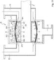
- R denotes a refiner.
- a rotation shaft 2 is provided inside a main body 1.
- a rotor 3 is attached to the rotation shaft 2.
- the rotor 3 has a mountain shape in which a center is high, and includes first and second opening portions 1H and 2H, both ends of which are open. Further, a space 3K is included inside the rotor 3.
- a rotor beating portion is provided on a surface of the rotor 3 except for a center of the rotor 3 in a longitudinal direction.
- the rotor beating portion has a groove between a bar (blade) and a bar (blade), and has a plurality of through-holes penetrating therethrough (see FIG. 11 to FIG. 16 , the through-holes are not illustrated in FIG. 13 and FIG. 15 ).
- the rotor beating portion includes a first rotor beating portion 31 in which a plurality of first bars (blades) B1 is provided on a surface of the rotor 3, a first groove M1 is provided between a first bar B1 and a first bar B1, and a plurality of first through-holes H1 is provided to penetrate therethrough, and a second rotor beating portion 32 in which a plurality of second bars (blades) B2 is provided on a surface of the rotor 3, a second groove M2 is provided between a second bar B2 and a second bar B2, and a plurality of second through-holes H2 is provided to penetrate therethrough.
- first bar B1 of the first rotor beating portion 31 is inclined such that a raw material is guided from a small diameter side of the rotor 3 to a large diameter side of the rotor 3.
- second bar B2 of the second rotor beating portion 32 is inclined such that a raw material is guided from the small diameter side of the rotor 3 to the large diameter side of the rotor 3.
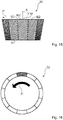
- the first bar B1 of the first rotor beating portion 31 is inclined (an angle A of FIG. 13 is about 5° to about 30°) such that a rear end N of the first bar B1 moves with respect to a front end M of the first bar B1 in a rotation direction of a first rotor (for example, a clockwise direction P illustrated in FIG. 13 and FIG. 14 ) in plan view in which a deep side of the first rotor beating portion 31 is positioned at a large diameter of the first rotor and a near side of the first rotor beating portion 31 is positioned at a small diameter of the first rotor (see FIG.
- FIG. 17 and FIG. 18 illustrate a case in which the rotation direction of the first rotor is set to a counterclockwise direction.
- the second bar B2 of the second rotor beating portion 32 is inclined (an angle A of FIG. 15 is about 5° to about 30°) such that a rear end N' of the second bar B2 moves with respect to a front end M' of the second bar B2 in a rotation direction of a second rotor (for example, a counterclockwise direction P' illustrated in FIG. 15 and FIG. 16 ) in plan view in which a deep side of the second rotor beating portion 32 is positioned at a large diameter of the second rotor and a near side of the second rotor beating portion 32 is positioned at a small diameter of the second rotor (see FIG.
- FIG. 19 and FIG. 20 illustrate a case in which the rotation direction of the second rotor is set to a clockwise direction.
- the through-holes H1 and H2 may have a circular shape or a rectangular shape (not illustrated). The shape is not limited.
- a stator 4 is provided in the main body 1 to oppose the rotor 3 described above.
- a stator beating portion opposes the rotor beating portion, is provided on a surface of the stator 4, has a groove between a bar (blade) and a bar (blade), and has a plurality of through-holes penetrating therethrough.
- the stator beating portion includes a first stator beating portion 41 provided on the surface and a second stator beating portion 42 provided on the surface.
- the first stator beating portion 41 has a first' groove (not illustrated) between a first' bar B1' and a first' bar B1', and has a plurality of first' through-holes H1' penetrating therethrough
- the second stator beating portion 42 has a second' groove (not illustrated) between a second' bar B2' and a second' bar B2', and has a plurality of second' through-holes H2' penetrating therethrough.
- the through-holes H1' and H2' may have a circular shape or a rectangular shape (not illustrated). The shape is not limited.
- Reference numeral 11 illustrated in FIG. 11 denotes a first raw material supply portion.
- the first raw material supply portion 11 is provided in the main body 1 to supply a raw material (papermaking raw material) from a side of a first opening portion 1H.
- Reference numeral 12 denotes a second raw material supply portion.
- the second raw material supply portion 12 supplies a raw material from a side of a second opening portion 2H.
- a central opening portion H is formed at a central portion of the stator beating portion, and a raw material discharge portion 5 discharges a raw material beaten inside the main body 1 to the outside of the main body 1.
- the raw material from the first raw material supply portion 11 approaches end portions X of the first stator beating portion 41 and the first rotor beating portion 31 on a side close to the first raw material supply portion 11, and the first opening portion 1H.
- the raw material from the second raw material supply portion 12 approaches end portions X' of the second stator beating portion 42 and the second rotor beating portion 32 on a side close to the second raw material supply portion 12, and the second opening portion 2H.
- End portions Y of the first stator beating portion 41 and the first rotor beating portion 31 on a side far from the first raw material supply portion 11 approaches the central opening portion H.
- End portions Y' of the second stator beating portion 42 and the second rotor beating portion 32 on a side far from the second raw material supply portion 12 approaches the central opening portion H.
- the plurality of first' through-holes H1' of the first stator beating portion 41, the plurality of second' through-holes H2' of the second stator beating portion 42, and the central opening portion H communicate with the raw material discharge portion 5.
- the raw material supplied from the first raw material supply portion 11 is guided from the first opening portion 1H and the end portions X of the first stator beating portion 41 and the first rotor beating portion 31 to the beating portions 31 and 41.
- the raw material supplied from the second raw material supply portion 12 is guided from the second opening portion 2H and the end portions X' of the second stator beating portion 42 and the second rotor beating portion 32 to the beating portions 32 and 42.
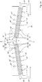
- a portion of a raw material guided to the first opening portion 1H of the rotor 3 and the space 3K of the rotor 3 is beaten by passing through the plurality of first through-holes H1 of the first rotor beating portion 31 and the plurality of first' through-holes H1' of the first stator beating portion 41, and is discharged to the outside of the first stator beating portion 41 from the plurality of first' through-holes H1' of the first stator beating portion 41 (see a flow of arrows a1 to a1' illustrated in FIG. 12 ).
- a portion of a raw material guided to the second opening portion 2H of the rotor 3 and the space 3K of the rotor 3 is beaten by passing through the plurality of second through-holes H2 of the second rotor beating portion 32 and the plurality of second' through-holes H2' of the second stator beating portion 42, and is discharged to the outside of the second stator beating portion 42 from the plurality of second' through-holes H2' of the second stator beating portion 42 (see a flow of arrows a2 to a2' illustrated in FIG. 12 ).
- a portion of a raw material guided to the first opening portion 1H of the rotor 3 and the space 3K of the rotor 3 passes through the plurality of first through-holes H1 of the first rotor beating portion 31 on a side close to the large diameter side of the first rotor, is beaten by passing through a gap between the first stator beating portion 41 and the first rotor beating portion 31, and is discharged to the outside of the first stator beating portion 41 and the first rotor beating portion 31 through the central opening portion H from the end portions Y of the first stator beating portion 41 and the first rotor beating portion 31 on the side far from the first raw material supply portion 11 (see a flow of arrows b1 to b1' illustrated in FIG. 12 ).
- a portion of a raw material guided to the second opening portion 2H of the rotor and the space 3K of the rotor 3 passes through the plurality of second through-holes H2 of the second rotor beating portion 32 on a side close to the large diameter side of the second rotor, is beaten by passing through a gap between the second stator beating portion 42 and the second rotor beating portion 32, and is discharged to the outside of the second stator beating portion 42 and the second rotor beating portion 32 through the central opening portion H from the end portions Y' of the second stator beating portion 42 and the second rotor beating portion 32 on a side far from the second raw material supply portion 12 (see a flow of arrows b2 to b2' illustrated in FIG. 12 ).
- a raw material guided to between the first stator beating portion 41 and the first rotor beating portion 31 on the small diameter side corresponding to the end portions X on the side close to the first raw material supply portion 11 is beaten by passing through the first stator beating portion 41 and the first rotor beating portion 31, and is discharged to the outside of the first stator beating portion 41 from the plurality of first' through-holes H1' of the first stator beating portion 41 (see a flow of arrows c1 to c1' illustrated in FIG. 12 ).
- a raw material guided to between the second stator beating portion 42 and the second rotor beating portion 32 on the small diameter side corresponding to the end portions X' on the side close to the second raw material supply portion 12 is beaten by passing through the second stator beating portion 42 and the second rotor beating portion 32, and is discharged to the outside of the second stator beating portion 42 from the plurality of second' through-holes H2' of the second stator beating portion 42 (see a flow of arrows c2 to c2' illustrated in FIG. 12 ).
- the raw material beaten by passing through the plurality of first through-holes H1 of the first rotor beating portion 31 and the plurality of first' through-holes H1' of the first stator beating portion 41 is discharged to the outside of the first stator beating portion 41 from the plurality of first' through-holes H1' of the first stator beating portion 41.
- the raw material beaten by passing through the plurality of second through-holes H2 of the second rotor beating portion 32 and the plurality of second' through-holes H2' of the second stator beating portion 42 is discharged to the outside of the second stator beating portion 42 from the plurality of second' through-holes H2' of the second stator beating portion 42.
- the raw material passing through the plurality of first through-holes H1 of the first rotor beating portion 31 on the side close to the large diameter side of the first rotor, and beaten by passing through the gap between the first stator beating portion 41 and the first rotor beating portion 31 is discharged to the outside of the first stator beating portion 41 and the first rotor beating portion 31 through the central opening portion H from the end portions Y of the first stator beating portion 41 and the first rotor beating portion 31 on the side far from the first raw material supply portion 11.
- the raw material passing through the plurality of second through-holes H2 of the second rotor beating portion 32 on the side close to the large diameter side of the second rotor, and beaten by passing through the gap between the second stator beating portion 42 and the second rotor beating portion 32 is discharged to the outside of the second stator beating portion 42 and the second rotor beating portion 32 through the central opening portion H from the end portions Y' of the second stator beating portion 42 and the second rotor beating portion 32 on the side far from the second raw material supply portion 12.
- the raw material guided to between the first stator beating portion 41 and the first rotor beating portion 31 on the small diameter side corresponding to the end portions X on the side close to the first raw material supply portion 11 is beaten by passing through the first stator beating portion 41 and the first rotor beating portion 31, and is discharged to the outside of the first stator beating portion 41 from the plurality of first' through-holes H1' of the first stator beating portion 41.
- the raw material guided to between the second stator beating portion 42 and the second rotor beating portion 32 on the small diameter side corresponding to the end portions X' on the side close to the second raw material supply portion 12 is beaten by passing through the second stator beating portion 42 and the second rotor beating portion 32, and is discharged to the outside of the second stator beating portion 42 from the plurality of second' through-holes H2' of the second stator beating portion 42.
- an increase in processing capability may be attempted by allowing a large amount of raw material to flow through the beating portions.
- the rotor 3 of the refiner R described above is not restricted to the rotor of FIG. 11 .
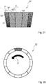
- a rotor of FIG. 21 may be employed.
- a rotor 3 illustrated in FIG. 21 corresponds to first and second tapered rotors 3A and 3B.
- a small diameter side of the first tapered rotor 3A corresponds to a first opening portion 1H of the rotor 3, and a large diameter side of the first tapered rotor 3A is blocked.
- a small diameter side of the second tapered rotor 3B corresponds to a second opening portion 2H of the rotor 3, and a large diameter side of the second tapered rotor 3B is blocked.
- first tapered rotor 3A and the large diameter side of the second tapered rotor 3B oppose each other, and are attached to a rotation shaft 2.
- two raw material supply portions corresponding to the first and second raw material supply portions 11 and 12 are provided as a raw material supply portion that supplies a raw material into the main body 1.
- the invention is not limited thereto.
- one raw material supply portion may be provided.
- reference numeral 11' illustrated in FIG. 22 denotes a raw material supply portion.
- the raw material supply portion 11' is provided in a main body 1 to supply a raw material from a side of a first opening portion 1H.
- the raw material supply portion 11' is closer to the first opening portion 1H than to a second opening portion 2H.
- the second opening portion 2H opposes an inner wall 1K of the main body 1
- a raw material discharged from the second opening portion 2H collides with the inner wall 1K of the main body 1 that opposes the second opening portion 2H, and the colliding raw material is guided to between a second stator beating portion 42 and a second rotor beating portion 32.
- a refiner R illustrated in FIG. 22 is similar to the refiners R of the above-described embodiments illustrated in FIG. 11 to FIG. 21 except that one raw material supply portion 11' is provided, and the second opening portion 2H opposes the inner wall 1K of the main body 1.
- FIG. 11 to FIG. 21 are quoted.
- the same reference numeral will be applied to the same portion of FIG. 22 as that of FIG. 11 to FIG. 21 , and a part of description will be omitted.
- a central opening portion H is formed at a central portion of a stator beating portion, a raw material from the raw material supply portion 11' approaches end portions X of a first stator beating portion 41 and a first rotor beating portion 31 on a side close to the raw material supply portion 11', and the first opening portion 1H, end portions Y of the first stator beating portion 41 and the first rotor beating portion 31 on a large diameter side face the central opening portion H, end portions Y" of the second stator beating portion 42 and the second rotor beating portion 32 on a large diameter side face the central opening portion H, and a plurality of first' through-holes H1' of the first stator beating portion 41, a plurality of second' through-holes H2' of the second stator beating portion 42, and the central opening portion H communicate with a raw material discharge portion 5.
- a raw material supplied from the raw material supply portion 11' is guided to the beating portions 31 and 41 from the first opening portion 1H and the end portions X of the first stator beating portion 41 and the first rotor beating portion 31.
- a portion of a raw material guided to a space 3K of a rotor 3 is discharged from the second rotor beating portion 32 and the second opening portion 2H.
- a portion of a raw material guided to the first opening portion 1H of the rotor 3 and the space 3K of the rotor 3 is beaten by passing through a plurality of first through-holes H1 of the first rotor beating portion 31 and the plurality of first' through-holes H1' of the first stator beating portion 41, and is discharged to the outside of the first stator beating portion 41 from the plurality of first' through-holes H1' of the first stator beating portion 41 (see a flow of arrows a1 to a1' illustrated in FIG. 22 ).
- a portion of a raw material guided to the space 3K of the rotor 3 is beaten by passing through a plurality of second through-holes H2 of the second rotor beating portion 32 and the plurality of second' through-holes H2' of the second stator beating portion 42, and is discharged to the outside of the second stator beating portion 42 from the plurality of second' through-holes H2' of the second stator beating portion 42 (see a flow of arrows a2 to a2' illustrated in FIG. 22 ).
- a portion of a raw material guided to the first opening portion 1H of the rotor 3 and the space 3K of the rotor 3 passes through the plurality of first through-holes H1 of the first rotor beating portion 31 on a side close to a large diameter side of a first rotor, is beaten by passing through a gap between the first stator beating portion 41 and the first rotor beating portion 31, and is discharged to the outside of the first stator beating portion 41 and the first rotor beating portion 31 through the central opening portion H from the end portions Y of the first stator beating portion 41 and the first rotor beating portion 31 on the large diameter side (see a flow of arrows b1 to b1' illustrated in FIG. 22 ) .
- a portion of a raw material guided to the space 3K of the rotor 3 passes through the plurality of second through-holes H2 of the second rotor beating portion 32 on a side close to a large diameter side of a second rotor, is beaten by passing through a gap between the second stator beating portion 42 and the second rotor beating portion 32, and is discharged to the outside of the second stator beating portion 42 and the second rotor beating portion 32 through the central opening portion H from the end portions Y' of the second stator beating portion 42 and the second rotor beating portion 32 on the large diameter side (see a flow of arrows b2 to b2' illustrated in FIG. 22 ).
- a raw material guided to between the first stator beating portion 41 and the first rotor beating portion 31 on a small diameter side corresponding to the end portions X on a side close to the raw material supply portion 11' is beaten by passing through the first stator beating portion 41 and the first rotor beating portion 31, and is discharged to the outside of the first stator beating portion 41 from the plurality of first' through-holes H1' of the first stator beating portion 41 (see a flow of arrows c1 to c1' illustrated in FIG. 22 ).
- the raw material beaten by passing through the plurality of first through-holes H1 of the first rotor beating portion 31 and the plurality of first' through-holes H1' of the first stator beating portion 41 is discharged to the outside of the first stator beating portion 41 from the plurality of first' through-holes H1' of the first stator beating portion 41
- the raw material beaten by passing through the plurality of second through-holes H2 of the second rotor beating portion 32 and the plurality of second' through-holes H2' of the second stator beating portion 42 is discharged to the outside of the second stator beating portion 42 from the plurality of second' through-holes H2' of the second stator beating portion 42
- the raw material beaten by passing between the first stator beating portion 41 and the first rotor beating portion 31 is discharged to the outside of the first stator beating portion 41 and the first rotor beating portion 31 from the central opening portion H provided at the center of the stator beating portion, and the raw material beaten by passing between the second stator beating portion 42 and the second rotor beating portion 32 is discharged to the outside of the second stator beating portion 42 and the second rotor beating portion 32 from the central opening portion H provided at the center of the stator beating portion.
- a portion of a raw material discharged to the outside of a first stator beating portion 41 from a first' through-hole H1' may be beaten by being guided to between the first stator beating portion 41 and a first rotor beating portion 31 from a central opening portion H provided in a part of the stator beating portion opposing a center of the rotor beating portion.
- a portion of a raw material discharged to the outside of a second stator beating portion 42 from a second' through-hole H2' may be beaten by being guided to between the second stator beating portion 42 and a second rotor beating portion 32 from the central opening portion H provided in the part of the stator beating portion opposing the center of the rotor beating portion.
- a portion of a raw material introduced to the first stator beating portion 41 and the first rotor beating portion 31 from a plurality of first through-holes H1 of the first rotor beating portion 31 on a side close to a small diameter side of a first rotor may be returned to the small diameter side of the first rotor.
- a portion of a raw material introduced to the second stator beating portion 42 and the second rotor beating portion 32 from a plurality of second through-holes H2 of the second rotor beating portion 32 on a side close to a small diameter side of a second rotor may be returned to the small diameter side of the second rotor. In this way, an increase in processing capability may be attempted.
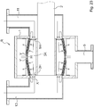
- R denotes a refiner.
- a rotation shaft 2 is provided inside a main body 1.
- a rotor 3 is attached to the rotation shaft 2.
- the rotor 3 has a mountain shape in which a center is high, and includes first and second opening portions 1H and 2H, both ends of which are open. Further, a space 3K is included inside the rotor 3.
- the rotor beating portion is provided on a surface of the rotor 3 except for a center of the rotor 3 in a longitudinal direction.
- the rotor beating portion has a groove between a bar (blade) and a bar (blade), and has a plurality of through-holes penetrating therethrough (see FIG. 24 to FIG. 32 , the through-holes are not illustrated in FIG. 25 , FIG. 27 , FIG. 29 , and FIG. 31 ).
- the rotor beating portion includes the first rotor beating portion 31 provided on a surface of the rotor 3 and the second rotor beating portion 32 provided on a surface of the rotor 3.
- the first rotor beating portion 31 has a first groove M1 between a first bar B1 and a first bar B1 and has a plurality of first through-holes H1 penetrating therethrough
- the second rotor beating portion 32 has a second groove M2 between a second bar B2 and a second bar B2 and has a plurality of second through-holes H2 penetrating therethrough.
- first bar B1 of the first rotor beating portion 31 is inclined such that a raw material is guided from a large diameter side of the rotor 3 to a small diameter side of the rotor 3.
- second bar B2 of the second rotor beating portion 32 is inclined such that a raw material is guided from the large diameter side of the rotor 3 to the small diameter side of the rotor 3.
- the first bar B1 of the first rotor beating portion 31 is inclined (an angle A of FIG. 25 is about 5° to about 30°) such that a front end M of the first bar B1 moves with respect to a rear end N of the first bar B1 in a rotation direction of the first rotor (for example, a clockwise direction P illustrated in FIG. 25 and FIG. 26 ) in plan view in which a deep side of the first rotor beating portion 31 is positioned at a large diameter of the first rotor and a near side of the first rotor beating portion 31 is positioned at a small diameter of the first rotor (see FIG.
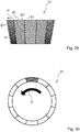
- FIG. 29 and FIG. 30 illustrate a case in which the rotation direction of the first rotor is set to a counterclockwise direction P'.
- the second bar B2 of the second rotor beating portion 32 is inclined (an angle A of FIG. 27 is about 5° to about 30°) such that a front end M' of the second bar B2 moves with respect to a rear end N' of the second bar B2 in a rotation direction of the second rotor (for example, a counterclockwise direction P' illustrated in FIG. 27 and FIG. 28 ) in plan view in which a deep side of the second rotor beating portion 32 is positioned at a large diameter of the second rotor and a near side of the second rotor beating portion 32 is positioned at a small diameter of the second rotor (see FIG.
- FIG. 31 and FIG. 32 illustrate a case in which the rotation direction of the second rotor is set to a clockwise direction P.
- the through-holes H1 and H2 may have a circular shape or a rectangular shape (not illustrated). The shape is not limited.
- a stator 4 is provided in the main body 1 to oppose the rotor 3 described above.
- the stator beating portion opposes the rotor beating portion, is provided on a surface of the stator 4, has a groove between a bar (blade) and a bar (blade), and has a plurality of through-holes penetrating therethrough.
- the stator beating portion includes a first stator beating portion 41 provided on the surface and a second stator beating portion 42 provided on the surface.
- the first stator beating portion 41 has a first' groove (not illustrated) between a first' bar B1' and a first' bar B1', and has a plurality of first' through-holes H1' penetrating therethrough
- the second stator beating portion 42 has a second' groove (not illustrated) between a second' bar B2' and a second' bar B2', and has a plurality of second' through-holes H2' penetrating therethrough.
- the through-holes H1' and H2' may have a circular shape or a rectangular shape (not illustrated). The shape is not limited.
- Reference numeral 11 illustrated in FIG. 23 denotes a first raw material supply portion.
- the first raw material supply portion 11 is provided in the main body 1 to supply a raw material (papermaking raw material) from a side of a first opening portion 1H.
- Reference numeral 12 denotes a second raw material supply portion.
- the second raw material supply portion 12 supplies a raw material from a side of a second opening portion 2H.
- a central opening portion H is formed at a central portion of the stator beating portion, and a raw material discharge portion 5 discharges a raw material beaten inside the main body 1 to the outside of the main body 1.
- end portions Y of the first stator beating portion 41 and the first rotor beating portion 31 on a side far from the first raw material supply portion 11 face the central opening portion H
- end portions Y' of the second stator beating portion 42 and the second rotor beating portion 32 on a side far from the second raw material supply portion 12 face the central opening portion H
- the raw material from the first raw material supply portion 11 approaches the first opening portion 1H and end portions X of the first stator beating portion 41 and the first rotor beating portion 31 on a side close to the first raw material supply portion 11
- the raw material from the second raw material supply portion 12 approaches the second opening portion 2H and end portions X' of the second stator beating portion 42 and the second rotor beating portion 32 on a side close to the second raw material supply portion 12.
- the plurality of first' through-holes H1' of the first stator beating portion 41, the plurality of second' through-holes H2' of the second stator beating portion 42, and the central opening portion H communicate with the raw material discharge portion 5.
- a portion of the raw material supplied from the first raw material supply portion 11 is beaten by passing through the first opening portion 1H, the space 3K of the rotor 3, the plurality of first through-holes H1 of the first rotor beating portion 31, and the plurality of first' through-holes H1' of the first stator beating portion 41, and is discharged to the outside of the first stator beating portion 41 from the plurality of first' through-holes H1' of the first stator beating portion 41 (see a flow of arrows a1 to a1' illustrated in FIG. 24 ).
- a portion of the raw material supplied from the second raw material supply portion 12 is beaten by passing through the second opening portion 2H, the space 3K of the rotor 3, the plurality of second through-holes H2 of the second rotor beating portion 32, and the plurality of second' through-holes H2' of the second stator beating portion 42, and is discharged to the outside of the second stator beating portion 42 from the plurality of second' through-holes H2' of the second stator beating portion 42 (see a flow of arrows a2 to a2' illustrated in FIG. 24 ).
- a portion of the raw material discharged to the outside of the first stator beating portion 41 from the plurality of first' through-holes H1' of the first stator beating portion 41 is beaten by being guided to between the first stator beating portion 41 and the first rotor beating portion 31 from the end portions Y of the first stator beating portion 41 and the first rotor beating portion 31 on the side far from the first raw material supply portion 11 through the central opening portion H, and is discharged to the outside of the first stator beating portion 41 from the plurality of first' through-holes H1' of the first stator beating portion 41 on a side close to the large diameter side of the first rotor (see a flow of arrows d1 to d1' illustrated in FIG. 24 ).
- a portion of the raw material discharged to the outside of the second stator beating portion 42 from the plurality of second' through-holes H2' of the second stator beating portion 42 is beaten by being guided to between the second stator beating portion 42 and the second rotor beating portion 32 from the end portions Y' of the second stator beating portion 42 and the second rotor beating portion 32 on a side far from the second raw material supply portion 12 through the central opening portion H, and is discharged to the outside of the second stator beating portion 42 from the plurality of second' through-holes H2' of the second stator beating portion 42 on a side close to the large diameter side of the second rotor (see a flow of arrows d2 to d2' illustrated in FIG. 24 ) .
- the portion of the raw material introduced to the first stator beating portion 41 and the first rotor beating portion 31 from the plurality of first through-holes H1 of the first rotor beating portion 31 on the side close to the small diameter side of a first rotor is returned to the small diameter side of the first rotor, is discharged from the end portions X of the first stator beating portion 41 and the first rotor beating portion 31 on the side close to the first raw material supply portion 11, joins the raw material supplied from the first raw material supply portion 11, is beaten by passing through the first opening portion 1H of the rotor 3, the space 3K of the rotor 3, the plurality of first through-holes H1 of the first rotor beating portion 31, and the plurality of first' through-holes H1' of the first stator beating portion 41, and is discharged to the outside of the first stator beating portion 41 from the plurality of first' through-holes H1' of the first stator beating portion 41 (see a flow of arrows e1 to e1'
- the portion of the raw material introduced to the second stator beating portion 42 and the second rotor beating portion 32 from the plurality of second through-holes H2 of the second rotor beating portion 32 on the side close to the small diameter side of the second rotor is returned to the small diameter side of the second rotor, is discharged from the end portions X' of the second stator beating portion 42 and the second rotor beating portion 32 on the side close to the second raw material supply portion 12, joins the raw material supplied from the second raw material supply portion 12, is beaten by passing through the second opening portion 2H of the rotor 3, the space 3K of the rotor 3, the plurality of second through-holes H2 of the second rotor beating portion 32, and the plurality of second' through-holes H2' of the second stator beating portion 42, and is discharged to the outside of the second stator beating portion 42 from the plurality of second' through-holes H2' of the second stator beating portion 42 (see a flow of arrows e2 to e2
- the raw material is discharged to the outside of the first stator beating portion 41 from the plurality of first' through-holes H1' of the first stator beating portion 41, the raw material is discharged to the outside of the second stator beating portion 42 from the plurality of second' through-holes H2' of the second stator beating portion 42, the portion of the raw material discharged to the outside of the first stator beating portion 41 is beaten by being guided to between the first stator beating portion 41 and the first rotor beating portion 31 from the end portions Y of the first stator beating portion 41 and the first rotor beating portion 31 on the side far from the first raw material supply portion 11 through the central opening portion H, and is discharged to the outside of the first stator beating portion 41 from the plurality of first' through-holes H1' of the first stator beating portion 41 on the side close to the large diameter side of the first rotor, the portion of the raw material discharged to the outside of the second stator
- the rotor 3 of the refiner R illustrated in FIG. 23 has a mountain shape in which a center is high, includes the first and second opening portions 1H and 2H, both ends of which are open, and has the space 3K therein.
- the invention is not limited thereto.
- the rotor 3 of the refiner R of the above-described embodiments illustrated in FIG. 23 and FIG. 33 has a mountain shape in which a center is high.
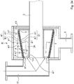
- FIG. 34 Another usefull example of a rotor 3 of a refiner R is illustrated in FIG. 34 .
- the example illustrated in FIG. 34 is not an embodiment of the present invention, but usefull for understanding the present invention.
- a rotation shaft 2 is provided inside a main body 1.
- a tapered rotor 3 having a space 3K therein is attached to the rotation shaft 2.
- the rotor 3 has a configuration in which a small diameter side serves as a small-diameter opening portion 1H and a large diameter side is blocked.
- a rotor beating portion 31 is provided on a surface of the rotor 3.
- the rotor beating portion 31 has a groove M1 between a bar (blade) B1 and a bar (blade) B1, and has a plurality of through-holes H1 penetrating therethrough.
- the bar B1 of the rotor beating portion 31 is inclined such that a raw material is guided from the large diameter side of the rotor 3 to the small diameter side of the rotor 3.
- the bar B1 of the rotor beating portion 31 is inclined (an angle A of FIG. 35 is about 5° to about 30°) such that a front end M of the bar B1 moves with respect to a rear end N of the bar B1 in a rotation direction of the rotor 3 (for example, a counterclockwise direction P' illustrated in FIG. 35 and FIG. 36 ) in plan view in which a deep side of the rotor beating portion 31 is positioned at a large diameter of the rotor 3 and a near side of the rotor beating portion 31 is positioned at a small diameter of the rotor 3 (see FIG.
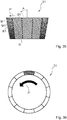
- FIG. 37 and FIG. 38 illustrate a case in which the rotation direction of the rotor 3 is set to a clockwise direction P.
- a stator 4 is provided in the main body 1 to oppose the above-described rotor 3.
- a stator beating portion 41 opposes the rotor beating portion 31, is provided on a surface of the stator 4, has a groove (not illustrated) between a bar (blade) B1' and a bar (blade) B1', and has a plurality of through-holes H1' penetrating therethrough.
- Reference numeral 11 illustrated in FIG. 34 denotes a raw material supply portion.
- the raw material supply portion 11 supplies the raw material (fibrous raw material) into the main body 1, and the raw material supply portion 11 supplies the raw material from a side of the opening portion 1H.
- Reference numeral 5 denotes a raw material discharge portion that discharges a beaten raw material to the outside of the main body 1.
- the raw material from the raw material supply portion 11 approaches end portions X of the stator beating portion 41 and the rotor beating portion 31 on a side closed to the raw material supply portion 11, and the small-diameter opening portion 1H of the rotor 3.
- the plurality of through-holes H1' of the stator beating portion 41 and end portions Y of the stator beating portion 41 and the rotor beating portion 31 on a side far from the raw material supply portion 11 communicate with the raw material discharge portion 5.
- a raw material beaten by passing through the small-diameter opening portion 1H of the rotor 3, the space 3K of the rotor 3, the plurality of through-holes H1 of the rotor beating portion 31, and the plurality of through-holes H1' of the stator beating portion 41 is discharged to the outside of the stator beating portion 41 from the plurality of through-holes H1' of the stator beating portion 41 (see a flow of arrows a1 to a1' illustrated in FIG. 34 ).
- a portion of the material discharged to the outside of the stator beating portion 41 from the through-holes H1' of the stator beating portion 41 is beaten by being guided to between the stator beating portion 41 and the rotor beating portion 31 from the end portions Y of the stator beating portion 41 and the rotor beating portion 31 on the side far from the raw material supply portion 11, and is discharged to the outside of the stator beating portion 41 from the plurality of through-holes H1' of the stator beating portion 41 on a side close to the large diameter side of the rotor 3 (see a flow of arrows d1 to d1' illustrated in FIG. 34 ) .
- a portion of a raw material introduced to the stator beating portion 41 and the rotor beating portion 31 from the plurality of through-holes H1 of the rotor beating portion 31 on a side close to the small diameter side of the rotor 3 is returned to the small diameter side of the rotor 3, is discharged from the end portions X of the stator beating portion 41 and the rotor beating portion 31 on a side close to the raw material supply portion 11, joins the raw material supplied from the raw material supply portion 11, is beaten by passing through the small-diameter opening portion 1H of the rotor 3, the space 3K of the rotor 3, the plurality of through-holes H1 of the rotor beating portion 31, and the plurality of through-holes H1' of the stator beating portion 41, and is discharged to the outside of the stator beating portion 41 from the plurality of through-holes H1' of the stator beating portion 41 (see a flow of arrows e1 to e1' to e" illustrated in FIG. 34
- the raw material is discharged to the outside of the stator beating portion 41 from the plurality of through-holes H1' of the stator beating portion 41, the portion of the material discharged to the outside of the stator beating portion 41 is beaten by being guided to between the stator beating portion 41 and the rotor beating portion 31 from the end portions Y of the stator beating portion 41 and the rotor beating portion 31 on the side far from the raw material supply portion 11, and is discharged to the outside of the stator beating portion 41 from the plurality of through-holes H1' of the stator beating portion 41 on the side close to the large diameter side of the rotor 3, and the portion of the raw material introduced to the stator beating portion 41 and the rotor beating portion 31 from the plurality of through-holes H1 of the rotor beating portion 31 on the side
Landscapes
- Engineering & Computer Science (AREA)
- Food Science & Technology (AREA)
- Paper (AREA)
- Crushing And Pulverization Processes (AREA)
Description
- The present invention relates to a refiner beating method and a refiner and particularly to a refiner beating method and a refiner causing an increase in processing capability.
- A Hitherto, a refiner is known as a device for beating pulp (for example, see
JP 4518711 B2 - In the refiner, a raw material is beaten by a rotor blade and a stator blade.
- However, since a gap formed between the rotor blade and the stator blade of the beating portion of the refiner is narrow, a large amount of a raw material cannot easily flow therebetween and hence processing capability is limited. Likewise, since the raw material to be processed passes through the narrow gap, there are problems in which pressure loss is large and processing capability cannot be increased with high efficiency.
-
WO 2009/153412 A1 discloses a refiner for refining fibrous material comprising at least one refining surface and at least one second refining surface, which are arranged at least partly substantially opposite to one another in such a manner that a refiner chamber is formed between them, to which the material to be defibrated is arranged to be fed. At least either the first refining surface or the second refining surface in the refiner is arranged such that it can be moved by a rotor with respect to the opposite refining surface. At least either the first refining surface or the second refining surface in the refiner comprises blade bars and blade grooves. -
WO 2012/101330 A1 discloses a conical refiner and a beating method, the refiner having a main body and a rotation shaft provided inside the main body, a perforated rotor and stator of mountain shape in which the centre is high, the rotor having first and second opening portions, both ends of which are open, and a space therein, the stator provided in the main body to oppose the rotor, a rotor beating portion having a groove between the bars, and a stator beating portion. - The invention is made in view of the above-described circumstances and an object of the invention is to provide a refiner beating method and a refiner causing an increase in processing capability.
- A refiner according to an invention comprises a main body, a rotation shaft provided inside the main body, a rotor attached to the rotation shaft and having a mountain shape in which a center is high, the rotor having first and second opening portions, both ends of which are open, and a space therein, a stator provided in the main body to oppose the rotor, a rotor beating portion provided on a surface of the rotor except for a center of the rotor in a longitudinal direction, the rotor beating portion having a groove between a bar and a bar and having a plurality of through-holes penetrating therethrough, a stator beating portion provided on a surface of the stator, the stator beating portion opposing the rotor beating portion, and having a groove between a bar and a bar and a plurality of through-holes penetrating therethrough, a first raw material supply portion for supplying a raw material from a side of the first opening portion, the first raw material supply portion being provided in the main body and being closer to the first opening portionthan to the second opening portion, and a raw material discharge portion for discharging a beaten raw material to an outside of the main body. The rotor beating portion includes a first rotor beating portion provided on a surface thereof and a second rotor beating portion provided on the surface, the first rotor beating portion having a first groove between a first bar and a first bar and a plurality of first through-holes penetrating therethrough, the second rotor beating portion having a second groove between a second bar and a second bar and a plurality of second through-holes penetrating therethrough. The first bar of the first rotor beating portion is configured, namely inclined, to guide a raw material from a small diameter side of the rotor to a large diameter side of the rotor or to guide a raw material from a large diameter side of the rotor to a small diameter side of the rotor. The second bar of the second rotor beating portion is configured, namely inclined, to guide a raw material from a small diameter side of the rotor to a large diameter side of the rotor or to guide a raw material from a large diameter side of the rotor to a small diameter side of the rotor.
- The first raw material supply portion approaches end portions of the first stator beating portion and the first rotor beating portion on a side close to the first raw material supply portion and the first opening portion, end portions of the first stator beating portion and the first rotor beating portion on the large diameter side face the central opening portion, end portions of the second stator beating portion and the second rotor beating portion on the large diameter side face the central opening portion. The plurality of through-holes of the first stator beating portion, the plurality of second through-holes of the second stator beating portion, and the central opening portion communicate with the raw material discharge portion.
- In a refining beating method, a portion of a raw material guided to the first opening portion of the rotor and the space of the rotor is beaten by passing through the plurality of first through-holes of the first rotor beating portion and the plurality of first through-holes of the first stator beating portion, and is discharged to an outside of the first stator beating portion from the plurality of first through-holes of the first stator beating portion.
- A portion of a raw material guided to the space of the rotor is beaten by passing through the plurality of second through-holes of the second rotor beating portion and the plurality of second through-holes of the second stator beating portion, and is discharged to an outside of the second stator beating portion from the plurality of second through-holes of the second stator beating portion.
- A portion of a raw material guided to the first opening portion of the rotor and the space of the rotor passes through the plurality of first through-holes of the first rotor beating portion on a side close to the large diameter side of the rotor, is beaten by passing through a gap between the first stator beating portion and the first rotor beating portion, and is discharged to an outside of the first stator beating portion and the first rotor beating portion through the central opening portion from end portions of the first stator beating portion and the first rotor beating portion on the large diameter side.
- A portion of a raw material guided to the space of the rotor passes through the plurality of second through-holes of the second rotor beating portion on a side close to the large diameter side of the rotor is beaten by passing through a gap between the second stator beating portion and the second rotor beating portion, and is discharged to an outside of the second stator beating portion and the second rotor beating portion through the central opening portion from end portions of the second stator beating portion and the second rotor beating portion on the large diameter side.
- A raw material guided to between the first stator beating portion and the first rotor beating portion on the small diameter side corresponding to the end portions on the side close to the first raw material supply portion is beaten by passing through the first stator beating portion and the first rotor beating portion, and is discharged to an outside of the first stator beating portion through the plurality of first through-holes of the first stator beating portion.
- A portion of a raw material guided to between the second stator beating portion and the second rotor beating portion on the small diameter side corresponding to end portions on a side close to the inner wall of the main body opposing the second opening portion , is beaten by passing through the second stator beating portion and the second rotor beating portion, and is discharged to an outside of the second stator beating portion from the plurality of second through-holes of the second stator beating portion.
- In the apparatus and method of the invention, a large amount of raw material flows through the beating portions. Thus, processing ability of the refiner can be increased.
-
-
FIG. 1 is a schematic cross-sectional view illustrating a refiner used in a refiner beating method according to an embodiment which is not an embodiment of the present invention, but which is usefull for understanding the present invention; -
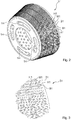
FIG. 2 is a schematic perspective view illustrating a rotor beating portion (rotor) ofFIG. 1 ; -
FIG. 3 is a schematic enlarged perspective view illustrating a part ofFIG. 2 ; -
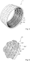
FIG. 4 is a schematic perspective view illustrating the stator beating portion (stator) ofFIG. 1 ; -
FIG. 5 is a schematic enlarged perspective view illustrating a part ofFIG. 4 ; -
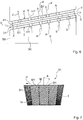
FIG. 6 is a schematic enlarged cross-sectional view illustrating a part of the beating portion ofFIG. 1 ; -
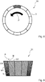
FIG. 7 is a schematic top view illustrating the rotor beating portion (the rotor) ofFIG. 2 ; -
FIG. 8 is a schematic side view ofFIG. 7 ; -
FIG. 9 is a schematic top view illustrating a rotor beating portion (rotor) of the other embodiment different from the rotor beating portion (the rotor) ofFIG. 7 ; -
FIG. 10 is a schematic side view ofFIG. 9 ; -
FIG. 11 is a schematic cross-sectional view illustrating a refiner used in a refiner beating method according to an embodiment of the invention; -
FIG. 12 is an enlarged cross-sectional view illustrating a part of a beating portion ofFIG. 11 ; -
FIG. 13 is a schematic top view illustrating a first rotor beating portion (first rotor) ofFIG. 11 ; -
FIG. 14 is a schematic side view ofFIG. 13 ; -
FIG. 15 is a schematic top view illustrating a second rotor beating portion (second rotor) ofFIG. 11 ; -
FIG. 16 is a schematic side view ofFIG. 15 ; -
FIG. 17 is a schematic top view illustrating a first rotor beating portion (first rotor) of the other embodiment different from the first rotor beating portion (first rotor) ofFIG. 13 ; -
FIG. 18 is a schematic side view ofFIG. 17 ; -
FIG. 19 is a schematic top view illustrating a second rotor beating portion (second rotor) of the other embodiment different from the second rotor beating portion (second rotor) ofFIG. 15 ; -
FIG. 20 is a schematic side view ofFIG. 19 ; -
FIG. 21 is a schematic cross-sectional view illustrating a refiner of the other embodiment different from the refiner ofFIG. 11 ; -
FIG. 22 is a schematic cross-sectional view illustrating a refiner of the other embodiment different from the refiner ofFIG. 21 ; -
FIG. 23 is a schematic cross-sectional view illustrating a refiner of the other embodiment different from the refiner ofFIG. 22 ; -
FIG. 24 is a schematic enlarged cross-sectional view illustrating a part ofFIG. 23 ; -
FIG. 25 is a schematic top view illustrating a first rotor beating portion (first rotor) ofFIG. 24 ; -
FIG. 26 is a schematic side view ofFIG. 25 ; -
FIG. 27 is a schematic top view illustrating a second rotor beating portion (second rotor) ofFIG. 21 ; -
FIG. 28 is a schematic side view ofFIG. 27 ; -
FIG. 29 is a schematic top view illustrating a first rotor beating portion (first rotor) of the other embodiment different from the first rotor beating portion (first rotor) ofFIG. 25 ; -
FIG. 30 is a schematic side view ofFIG. 29 ; -
FIG. 31 is a schematic top view illustrating a second rotor beating portion (second rotor) of the other embodiment different from the second rotor beating portion (second rotor) ofFIG. 27 ; -
FIG. 32 is a schematic side view ofFIG. 31 ; -
FIG. 33 is a schematic cross-sectional view illustrating a refiner of the other embodiment different from the refiner ofFIG. 23 ; -
FIG. 34 is a schematic cross-sectional view illustrating a refiner of another embodiment which is not an embodiment of the present invention but which is usefull for understanding the invention; -
FIG. 35 is a schematic top view illustrating a rotor beating portion (rotor) ofFIG. 34 ; -
FIG. 36 is a schematic side view ofFIG. 35 ; -
FIG. 37 is a schematic top view illustrating a rotor beating portion (rotor) of the other embodiment different from the rotor beating portion (rotor) ofFIG. 35 ; and -
FIG. 38 is a schematic side view ofFIG. 37 . - A refiner beating method according to an embodiment which is not an embodiment of the present invention, but which is usefull for understanding the present invention will be described with reference to
FIGS. 1 to 10 . - In
FIG. 1 , R indicates a refiner, and the refiner R has a configuration in which arotation shaft 2 is provided inside a main body 1. - A
tapered rotor 3 having aspace 3K therein is attached to therotation shaft 2. Therotor 3 has a configuration in which a small diameter side serves as a small-diameter opening portion 1H and a large diameter side is blocked. - As shown in
FIGS. 1 to 3 andFIGS. 6 to 8 , arotor beating portion 31 has a configuration in which a plurality of bars (blades) B1 is provided on a surface of therotor 3, a groove M1 is provided between a bar (blade) B1 and a bar (blade) B1, and a plurality of through-holes H1 is provided so as to penetrate therotor 3. - That is, a bar locking portion (not illustrated) provided in the bar B1 is locked to a bar locked portion (not illustrated) provided in the
rotor beating portion 31, the bar B1 is provided across the through-hole H1, and the bar locking portion (not illustrated) locked to the bar locked portion (not illustrated) is fixed by welding or the like. - Additionally, the through-hole H1 may have a circular shape (
FIGS. 2 and 3 ) or a rectangular shape. The shape is not limited. - Then, the bar B1 of the
rotor beating portion 31 is inclined so as to guide a raw material from the small diameter side of therotor 3 to the large diameter side of therotor 3. - That is, as illustrated in
FIGS. 7 and8 , the bar B1 of therotor beating portion 31 is inclined (an angle A ofFIG. 7 is about 5° to about 30°) such that a rear end N of the bar B1 moves with respect to a front end M of the bar B1 in a rotation direction of the rotor 3 (for example, a counterclockwise direction P' illustrated inFIG. 7 andFIG. 8 ) in plan view in which a deep side of therotor beating portion 31 is positioned at a large diameter of therotor 3 and a near side of therotor beating portion 31 is positioned at a small diameter of the rotor 3 (seeFIG. 7 ), and the raw material is allowed to flow from the small diameter side of therotor 3 to the large diameter side of therotor 3.FIG. 9 andFIG. 10 illustrate a case in which the rotation direction of therotor 3 is set to a clockwise direction P. - In addition, a
stator 4 is provided in the main body 1 to oppose therotor 3 described above. - As described in
FIG. 1 ,FIG. 4, and FIG. 5 , astator beating portion 41 opposes therotor beating portion 31, and has a plurality of bars (blades) B1' provided on a surface of thestator 4, a groove M1' provided between a bar (blade) B1' and a bar (blade) B1', and a plurality of through-holes H1' provided so as to penetrate thestator 4. - That is, a bar locking portion (not illustrated) provided in the bar B1' is locked to a bar locked portion (not illustrated) provided in the
stator beating portion 41, the bar B1' is provided across the through-hole H1', and the bar locking portion (not illustrated) locked to the bar locked portion (not illustrated) is fixed by welding or the like. - Additionally, the through-hole H1' may have a circular shape (
FIGS. 4 and 5 ) or a rectangular shape. The shape is not limited. - In this way, when the bars B1 and B1' of the beating portions of the
rotor 3 and/or thestator 4 are installed across the through-holes H1 and H1', lengths of the bars B1 and B1' may be made long, and beating ability may be increased accordingly. -
Reference numeral 11 illustrated inFIG. 1 denotes a raw material supply portion. The rawmaterial supply portion 11 supplies the raw material (fibrous raw material) into the main body 1, and the rawmaterial supply portion 11 supplies the raw material from a side of theopening portion 1H. - The raw material from the raw
material supply portion 11 is configured to approach end portions X of thestator beating portion 41 and therotor beating portion 31 on a side closed to the rawmaterial supply portion 11, and the small-diameter opening portion 1H of the rotor. - In addition,
reference numeral 5 illustrated inFIG. 1 denotes a raw material discharge portion that discharges the raw material beaten inside the main body 1 to the outside of the main body 1, and the plurality of through-holes H1' of thestator beating portion 41 and end portions Y of thestator beating portion 41 and therotor beating portion 31 on a side far from the rawmaterial supply portion 11 communicate with the rawmaterial discharge portion 5. - Therefore, according to the above-described refiner R (or refiner beating method), the raw material into the main body 1 is supplied from the raw
material supply portion 11. - A portion of the raw material supplied from the raw
material supply portion 11 is guided into therotor 3 through the small-diameter opening portion 1H, and another portion of the raw material is guided to between thestator beating portion 41 and therotor beating portion 31. - As illustrated in
FIG. 6 , a portion of the raw material guided to the small-diameter opening portion 1H of therotor 3 and thespace 3K of therotor 3 are beaten by passing through the plurality of through-holes H1 of therotor beating portion 31 and the plurality of through-holes H1' of thestator beating portion 41, and are discharged to the outside of thestator beating portion 41 from the plurality of through-holes H1' of the stator beating portion 41 (see a flow of arrows a to a' illustrated inFIG. 6 ) - In addition, another portion of the raw material guided to the small-
diameter opening portion 1H of therotor 3 and thespace 3K of therotor 3 passes through the plurality of through-holes H1 of therotor beating portion 31 on a side closed to the large diameter side of therotor 3, is beaten by passing through a gap between thestator beating portion 41 and therotor beating portion 31, and is discharged to the outside of thestator beating portion 41 and therotor beating portion 31 from the end portions Y of thestator beating portion 41 and therotor beating portion 31 on the side far from the raw material supply portion 11 (see a flow of arrows b to b' illustrated inFIG. 6 ) - In addition, the raw material guided to between the
stator beating portion 41 and therotor beating portion 31 on the small diameter side corresponding to the end portions X on the side closed to the rawmaterial supply portion 11 is beaten by passing through thestator beating portion 41 and therotor beating portion 31, and is discharged to the outside of thestator beating portion 41 from the plurality of through-holes H1' of the stator beating portion 41 (see a flow of arrows c to c' illustrated inFIG. 6 ) - In this way, according to the above-described refiner beating method (or refiner R), the raw material beaten by passing through the plurality of through-holes H1 of the rotor beating portion 31 and the plurality of through-holes H1' of the stator beating portion 41 is discharged to the outside of the stator beating portion 41 from the plurality of through-holes H1' of the stator beating portion 41, the raw material passing through the plurality of through-holes H1 of the rotor beating portion 31 on the side close to the large diameter side of the rotor 3 and beaten by passing through a gap between the stator beating portion 41 and the rotor beating portion 31 is discharged to the outside of the stator beating portion 41 and the rotor beating portion 31 from the end portions Y of the stator beating portion 41 and the rotor beating portion 31 on the side far from the raw material supply portion 11, and the raw material guided to between the stator beating portion 41 and the rotor beating portion 31 on the small diameter side corresponding to the end portions X on the side closed to the raw material supply portion 11 is beaten by passing through the stator beating portion 41 and the rotor beating portion 31, and is discharged to the outside of the stator beating portion 41 from the plurality of through-holes H1' of the stator beating portion 41. Thus, processing capability may be increased by allowing a large amount of raw material to flow through the beating portions.
- In the above-described refiner R of the embodiment illustrated in
FIG. 1 to FIG. 10 , when a surface area (lateral area) of therotor 3 of the refiner R illustrated inFIG. 1 except for both ends is set to S, and a diameter of therotor 3 on the large diameter side is set to D1, and, for example, when the surface area (lateral area) of therotor 3 illustrated inFIG. 1 except for the both ends is attempted to be increased to 2S to increase a refining zone, the diameter of therotor 3 on the large diameter side becomes D2 (D2 > D1). - Incidentally, if the
rotor 3 of the refiner R illustrated inFIG. 1 is symmetrically provided as illustrated inFIG. 11 of an embodiment of the present invention and which is described below, even when the surface area (lateral area) of therotor 3 except for the both ends is increased to 2S, the diameter of therotor 3 on the large diameter side becomes D1, which is the same as D1 ofFIG. 1 . - That is, when the surface area (lateral area) of the
rotor 3 except for the both ends is increased and used, if a shape illustrated inFIG. 11 is employed, the diameter may be made small to be D2 > D1. Thus, there is an effect that non-load power of the refiner R may be made small, and energy conservation may be attempted. - The above-mentioned "non-load power" refers to power consumed when the rotor and the stator are open, and the rotor is rotated in pulp suspension.
- Power used for actual refining is obtained by an equation of power = [power consumption of whole refiner] - [non-load power]. As non-load power decreases, total power may be more effectively used.
- That is, referring to
FIG. 11 , R denotes a refiner. In the refiner R, arotation shaft 2 is provided inside a main body 1. - A
rotor 3 is attached to therotation shaft 2. Here, therotor 3 has a mountain shape in which a center is high, and includes first andsecond opening portions space 3K is included inside therotor 3. - As illustrated in
FIG. 11 andFIG. 12 , a rotor beating portion is provided on a surface of therotor 3 except for a center of therotor 3 in a longitudinal direction. The rotor beating portion has a groove between a bar (blade) and a bar (blade), and has a plurality of through-holes penetrating therethrough (seeFIG. 11 to FIG. 16 , the through-holes are not illustrated inFIG. 13 andFIG. 15 ). - As illustrated in
FIG. 11 to FIG. 16 , the rotor beating portion includes a firstrotor beating portion 31 in which a plurality of first bars (blades) B1 is provided on a surface of therotor 3, a first groove M1 is provided between a first bar B1 and a first bar B1, and a plurality of first through-holes H1 is provided to penetrate therethrough, and a secondrotor beating portion 32 in which a plurality of second bars (blades) B2 is provided on a surface of therotor 3, a second groove M2 is provided between a second bar B2 and a second bar B2, and a plurality of second through-holes H2 is provided to penetrate therethrough. - In addition, the first bar B1 of the first
rotor beating portion 31 is inclined such that a raw material is guided from a small diameter side of therotor 3 to a large diameter side of therotor 3. Further, the second bar B2 of the secondrotor beating portion 32 is inclined such that a raw material is guided from the small diameter side of therotor 3 to the large diameter side of therotor 3. - That is, as illustrated in
FIGS. 13 and 14 , the first bar B1 of the firstrotor beating portion 31 is inclined (an angle A ofFIG. 13 is about 5° to about 30°) such that a rear end N of the first bar B1 moves with respect to a front end M of the first bar B1 in a rotation direction of a first rotor (for example, a clockwise direction P illustrated inFIG. 13 and FIG. 14 ) in plan view in which a deep side of the firstrotor beating portion 31 is positioned at a large diameter of the first rotor and a near side of the firstrotor beating portion 31 is positioned at a small diameter of the first rotor (seeFIG. 13 ), and the raw material is allowed to flow from the small diameter side of the first rotor to the large diameter side of the first rotor.FIG. 17 and FIG. 18 illustrate a case in which the rotation direction of the first rotor is set to a counterclockwise direction. - In addition, as illustrated in
FIGS. 15 and 16 , the second bar B2 of the secondrotor beating portion 32 is inclined (an angle A ofFIG. 15 is about 5° to about 30°) such that a rear end N' of the second bar B2 moves with respect to a front end M' of the second bar B2 in a rotation direction of a second rotor (for example, a counterclockwise direction P' illustrated inFIG. 15 and FIG. 16 ) in plan view in which a deep side of the secondrotor beating portion 32 is positioned at a large diameter of the second rotor and a near side of the secondrotor beating portion 32 is positioned at a small diameter of the second rotor (seeFIG. 15 ), and the raw material is allowed to flow from the small diameter side of the second rotor to the large diameter side of the second rotor.FIG. 19 and FIG. 20 illustrate a case in which the rotation direction of the second rotor is set to a clockwise direction. - Additionally, the through-holes H1 and H2 may have a circular shape or a rectangular shape (not illustrated). The shape is not limited.
- In addition, a
stator 4 is provided in the main body 1 to oppose therotor 3 described above. - As described in
FIG. 11 andFIG. 12 , a stator beating portion opposes the rotor beating portion, is provided on a surface of thestator 4, has a groove between a bar (blade) and a bar (blade), and has a plurality of through-holes penetrating therethrough. - The stator beating portion includes a first
stator beating portion 41 provided on the surface and a secondstator beating portion 42 provided on the surface. Here, the firststator beating portion 41 has a first' groove (not illustrated) between a first' bar B1' and a first' bar B1', and has a plurality of first' through-holes H1' penetrating therethrough, and the secondstator beating portion 42 has a second' groove (not illustrated) between a second' bar B2' and a second' bar B2', and has a plurality of second' through-holes H2' penetrating therethrough. - Additionally, the through-holes H1' and H2' may have a circular shape or a rectangular shape (not illustrated). The shape is not limited.
-
Reference numeral 11 illustrated inFIG. 11 denotes a first raw material supply portion. The first rawmaterial supply portion 11 is provided in the main body 1 to supply a raw material (papermaking raw material) from a side of afirst opening portion 1H.Reference numeral 12 denotes a second raw material supply portion. The second rawmaterial supply portion 12 supplies a raw material from a side of asecond opening portion 2H. - In addition, a central opening portion H is formed at a central portion of the stator beating portion, and a raw
material discharge portion 5 discharges a raw material beaten inside the main body 1 to the outside of the main body 1. - In addition, the raw material from the first raw
material supply portion 11 approaches end portions X of the firststator beating portion 41 and the firstrotor beating portion 31 on a side close to the first rawmaterial supply portion 11, and thefirst opening portion 1H. The raw material from the second rawmaterial supply portion 12 approaches end portions X' of the secondstator beating portion 42 and the secondrotor beating portion 32 on a side close to the second rawmaterial supply portion 12, and thesecond opening portion 2H. End portions Y of the firststator beating portion 41 and the firstrotor beating portion 31 on a side far from the first rawmaterial supply portion 11 approaches the central opening portion H. End portions Y' of the secondstator beating portion 42 and the secondrotor beating portion 32 on a side far from the second rawmaterial supply portion 12 approaches the central opening portion H. The plurality of first' through-holes H1' of the firststator beating portion 41, the plurality of second' through-holes H2' of the secondstator beating portion 42, and the central opening portion H communicate with the rawmaterial discharge portion 5. - Therefore, when a raw material is supplied by the first raw
material supply portion 11 and the second rawmaterial supply portion 12, the operation proceeds as follows. - The raw material supplied from the first raw
material supply portion 11 is guided from thefirst opening portion 1H and the end portions X of the firststator beating portion 41 and the firstrotor beating portion 31 to the beatingportions material supply portion 12 is guided from thesecond opening portion 2H and the end portions X' of the secondstator beating portion 42 and the secondrotor beating portion 32 to the beatingportions - That is, a portion of a raw material guided to the
first opening portion 1H of therotor 3 and thespace 3K of therotor 3 is beaten by passing through the plurality of first through-holes H1 of the firstrotor beating portion 31 and the plurality of first' through-holes H1' of the firststator beating portion 41, and is discharged to the outside of the firststator beating portion 41 from the plurality of first' through-holes H1' of the first stator beating portion 41 (see a flow of arrows a1 to a1' illustrated inFIG. 12 ). - In addition, a portion of a raw material guided to the
second opening portion 2H of therotor 3 and thespace 3K of therotor 3 is beaten by passing through the plurality of second through-holes H2 of the secondrotor beating portion 32 and the plurality of second' through-holes H2' of the secondstator beating portion 42, and is discharged to the outside of the secondstator beating portion 42 from the plurality of second' through-holes H2' of the second stator beating portion 42 (see a flow of arrows a2 to a2' illustrated inFIG. 12 ). - In addition, a portion of a raw material guided to the
first opening portion 1H of therotor 3 and thespace 3K of therotor 3 passes through the plurality of first through-holes H1 of the firstrotor beating portion 31 on a side close to the large diameter side of the first rotor, is beaten by passing through a gap between the firststator beating portion 41 and the firstrotor beating portion 31, and is discharged to the outside of the firststator beating portion 41 and the firstrotor beating portion 31 through the central opening portion H from the end portions Y of the firststator beating portion 41 and the firstrotor beating portion 31 on the side far from the first raw material supply portion 11 (see a flow of arrows b1 to b1' illustrated inFIG. 12 ). - In addition, a portion of a raw material guided to the
second opening portion 2H of the rotor and thespace 3K of therotor 3 passes through the plurality of second through-holes H2 of the secondrotor beating portion 32 on a side close to the large diameter side of the second rotor, is beaten by passing through a gap between the secondstator beating portion 42 and the secondrotor beating portion 32, and is discharged to the outside of the secondstator beating portion 42 and the secondrotor beating portion 32 through the central opening portion H from the end portions Y' of the secondstator beating portion 42 and the secondrotor beating portion 32 on a side far from the second raw material supply portion 12 (see a flow of arrows b2 to b2' illustrated inFIG. 12 ). - In addition, a raw material guided to between the first
stator beating portion 41 and the firstrotor beating portion 31 on the small diameter side corresponding to the end portions X on the side close to the first rawmaterial supply portion 11 is beaten by passing through the firststator beating portion 41 and the firstrotor beating portion 31, and is discharged to the outside of the firststator beating portion 41 from the plurality of first' through-holes H1' of the first stator beating portion 41 (see a flow of arrows c1 to c1' illustrated inFIG. 12 ). - In addition, a raw material guided to between the second
stator beating portion 42 and the secondrotor beating portion 32 on the small diameter side corresponding to the end portions X' on the side close to the second rawmaterial supply portion 12 is beaten by passing through the secondstator beating portion 42 and the secondrotor beating portion 32, and is discharged to the outside of the secondstator beating portion 42 from the plurality of second' through-holes H2' of the second stator beating portion 42 (see a flow of arrows c2 to c2' illustrated inFIG. 12 ). - In this way, according to the above-described refiner beating method (or refiner R), the raw material beaten by passing through the plurality of first through-holes H1 of the first
rotor beating portion 31 and the plurality of first' through-holes H1' of the firststator beating portion 41 is discharged to the outside of the firststator beating portion 41 from the plurality of first' through-holes H1' of the firststator beating portion 41. - In addition, the raw material beaten by passing through the plurality of second through-holes H2 of the second
rotor beating portion 32 and the plurality of second' through-holes H2' of the secondstator beating portion 42 is discharged to the outside of the secondstator beating portion 42 from the plurality of second' through-holes H2' of the secondstator beating portion 42. - The raw material passing through the plurality of first through-holes H1 of the first
rotor beating portion 31 on the side close to the large diameter side of the first rotor, and beaten by passing through the gap between the firststator beating portion 41 and the firstrotor beating portion 31 is discharged to the outside of the firststator beating portion 41 and the firstrotor beating portion 31 through the central opening portion H from the end portions Y of the firststator beating portion 41 and the firstrotor beating portion 31 on the side far from the first rawmaterial supply portion 11. - In addition, the raw material passing through the plurality of second through-holes H2 of the second
rotor beating portion 32 on the side close to the large diameter side of the second rotor, and beaten by passing through the gap between the secondstator beating portion 42 and the secondrotor beating portion 32 is discharged to the outside of the secondstator beating portion 42 and the secondrotor beating portion 32 through the central opening portion H from the end portions Y' of the secondstator beating portion 42 and the secondrotor beating portion 32 on the side far from the second rawmaterial supply portion 12. - In addition, the raw material guided to between the first
stator beating portion 41 and the firstrotor beating portion 31 on the small diameter side corresponding to the end portions X on the side close to the first rawmaterial supply portion 11 is beaten by passing through the firststator beating portion 41 and the firstrotor beating portion 31, and is discharged to the outside of the firststator beating portion 41 from the plurality of first' through-holes H1' of the firststator beating portion 41. - In addition, the raw material guided to between the second
stator beating portion 42 and the secondrotor beating portion 32 on the small diameter side corresponding to the end portions X' on the side close to the second rawmaterial supply portion 12 is beaten by passing through the secondstator beating portion 42 and the secondrotor beating portion 32, and is discharged to the outside of the secondstator beating portion 42 from the plurality of second' through-holes H2' of the secondstator beating portion 42. Thus, an increase in processing capability may be attempted by allowing a large amount of raw material to flow through the beating portions. - The
rotor 3 of the refiner R described above is not restricted to the rotor ofFIG. 11 . For example, a rotor ofFIG. 21 may be employed. - That is, a
rotor 3 illustrated inFIG. 21 corresponds to first and secondtapered rotors rotor 3A corresponds to afirst opening portion 1H of therotor 3, and a large diameter side of the first taperedrotor 3A is blocked. - In addition, a small diameter side of the second
tapered rotor 3B corresponds to asecond opening portion 2H of therotor 3, and a large diameter side of the secondtapered rotor 3B is blocked. - Further, the large diameter side of the first tapered
rotor 3A and the large diameter side of the secondtapered rotor 3B oppose each other, and are attached to arotation shaft 2. - In addition, in the refiners R of the embodiments illustrated in
FIG. 11 andFIG. 21 , two raw material supply portions corresponding to the first and second rawmaterial supply portions FIG. 22 , one raw material supply portion may be provided. - That is, reference numeral 11' illustrated in
FIG. 22 denotes a raw material supply portion. The raw material supply portion 11' is provided in a main body 1 to supply a raw material from a side of afirst opening portion 1H. Here, the raw material supply portion 11' is closer to thefirst opening portion 1H than to asecond opening portion 2H. - In addition, the
second opening portion 2H opposes aninner wall 1K of the main body 1, a raw material discharged from thesecond opening portion 2H collides with theinner wall 1K of the main body 1 that opposes thesecond opening portion 2H, and the colliding raw material is guided to between a secondstator beating portion 42 and a secondrotor beating portion 32. - A refiner R illustrated in
FIG. 22 is similar to the refiners R of the above-described embodiments illustrated inFIG. 11 to FIG. 21 except that one raw material supply portion 11' is provided, and thesecond opening portion 2H opposes theinner wall 1K of the main body 1. Thus, in the present embodiment, with regard to description of the refiner R illustrated inFIG. 22 ,FIG. 11 to FIG. 21 are quoted. In addition, the same reference numeral will be applied to the same portion ofFIG. 22 as that ofFIG. 11 to FIG. 21 , and a part of description will be omitted. - In the refiner R illustrated in
FIG. 22 , a central opening portion H is formed at a central portion of a stator beating portion, a raw material from the raw material supply portion 11' approaches end portions X of a firststator beating portion 41 and a firstrotor beating portion 31 on a side close to the raw material supply portion 11', and thefirst opening portion 1H, end portions Y of the firststator beating portion 41 and the firstrotor beating portion 31 on a large diameter side face the central opening portion H, end portions Y" of the secondstator beating portion 42 and the secondrotor beating portion 32 on a large diameter side face the central opening portion H, and a plurality of first' through-holes H1' of the firststator beating portion 41, a plurality of second' through-holes H2' of the secondstator beating portion 42, and the central opening portion H communicate with a rawmaterial discharge portion 5. - Therefore, when a raw material is supplied from the raw material supply portion 11', the operation proceeds as follows.
- A raw material supplied from the raw material supply portion 11' is guided to the beating
portions first opening portion 1H and the end portions X of the firststator beating portion 41 and the firstrotor beating portion 31. In addition, a portion of a raw material guided to aspace 3K of arotor 3 is discharged from the secondrotor beating portion 32 and thesecond opening portion 2H. - That is, a portion of a raw material guided to the
first opening portion 1H of therotor 3 and thespace 3K of therotor 3 is beaten by passing through a plurality of first through-holes H1 of the firstrotor beating portion 31 and the plurality of first' through-holes H1' of the firststator beating portion 41, and is discharged to the outside of the firststator beating portion 41 from the plurality of first' through-holes H1' of the first stator beating portion 41 (see a flow of arrows a1 to a1' illustrated inFIG. 22 ). - In addition, a portion of a raw material guided to the
space 3K of therotor 3 is beaten by passing through a plurality of second through-holes H2 of the secondrotor beating portion 32 and the plurality of second' through-holes H2' of the secondstator beating portion 42, and is discharged to the outside of the secondstator beating portion 42 from the plurality of second' through-holes H2' of the second stator beating portion 42 (see a flow of arrows a2 to a2' illustrated inFIG. 22 ). - In addition, a portion of a raw material guided to the
first opening portion 1H of therotor 3 and thespace 3K of therotor 3 passes through the plurality of first through-holes H1 of the firstrotor beating portion 31 on a side close to a large diameter side of a first rotor, is beaten by passing through a gap between the firststator beating portion 41 and the firstrotor beating portion 31, and is discharged to the outside of the firststator beating portion 41 and the firstrotor beating portion 31 through the central opening portion H from the end portions Y of the firststator beating portion 41 and the firstrotor beating portion 31 on the large diameter side (see a flow of arrows b1 to b1' illustrated inFIG. 22 ) . - In addition, a portion of a raw material guided to the
space 3K of therotor 3 passes through the plurality of second through-holes H2 of the secondrotor beating portion 32 on a side close to a large diameter side of a second rotor, is beaten by passing through a gap between the secondstator beating portion 42 and the secondrotor beating portion 32, and is discharged to the outside of the secondstator beating portion 42 and the secondrotor beating portion 32 through the central opening portion H from the end portions Y' of the secondstator beating portion 42 and the secondrotor beating portion 32 on the large diameter side (see a flow of arrows b2 to b2' illustrated inFIG. 22 ). - In addition, a raw material guided to between the first
stator beating portion 41 and the firstrotor beating portion 31 on a small diameter side corresponding to the end portions X on a side close to the raw material supply portion 11' is beaten by passing through the firststator beating portion 41 and the firstrotor beating portion 31, and is discharged to the outside of the firststator beating portion 41 from the plurality of first' through-holes H1' of the first stator beating portion 41 (see a flow of arrows c1 to c1' illustrated inFIG. 22 ). - In addition, a portion of the raw material discharged from the
second opening portion 2H collides with theinner wall 1K of the main body 1 that opposes thesecond opening portion 2H, is guided to between the secondstator beating portion 42 and the secondrotor beating portion 32 on the small diameter side corresponding to end portions X" on a side close to theinner wall 1K of the main body 1 that opposes thesecond opening portion 2H, is beaten by passing through the secondstator beating portion 42 and the secondrotor beating portion 32, and is discharged to the outside of the secondstator beating portion 42 from the plurality of second' through-holes H2' of the second stator beating portion 42 (see a flow of arrows c2 to c2' illustrated inFIG. 22 ). - In this way, according to the above-described refiner beating method (or refiner R) illustrated in
FIG. 22 , similarly to the refiners R (or refiner beating methods) illustrated inFIG. 11 to FIG. 21 ,
the raw material beaten by passing through the plurality of first through-holes H1 of the firstrotor beating portion 31 and the plurality of first' through-holes H1' of the firststator beating portion 41 is discharged to the outside of the firststator beating portion 41 from the plurality of first' through-holes H1' of the firststator beating portion 41,
the raw material beaten by passing through the plurality of second through-holes H2 of the secondrotor beating portion 32 and the plurality of second' through-holes H2' of the secondstator beating portion 42 is discharged to the outside of the secondstator beating portion 42 from the plurality of second' through-holes H2' of the secondstator beating portion 42,
the raw material passing through the plurality of first through-holes H1 of the firstrotor beating portion 31 on a side close to the large diameter side of the first rotor, and beaten by passing through the gap between the firststator beating portion 41 and the firstrotor beating portion 31 is discharged to the outside of the firststator beating portion 41 and the firstrotor beating portion 31 through the central opening portion H from the end portions Y of the firststator beating portion 41 and the firstrotor beating portion 31 on a side far from the raw material supply portion 11',
the raw material passing through the plurality of second through-holes H2 of the secondrotor beating portion 32 on the side close to the large diameter side of the second rotor, and beaten by passing through the gap between the secondstator beating portion 42 and the secondrotor beating portion 32 is discharged to the outside of the secondstator beating portion 42 and the secondrotor beating portion 32 through the central opening portion H from the end portions Y" of the secondstator beating portion 42 and the secondrotor beating portion 32 on the large diameter side,
the raw material guided to between the firststator beating portion 41 and the firstrotor beating portion 31 on the small diameter side corresponding to the end portions X on the side close to the raw material supply portion 11' is beaten by passing through the firststator beating portion 41 and the firstrotor beating portion 31, and is discharged to the outside of the firststator beating portion 41 from the plurality of first' through-holes H1' of the firststator beating portion 41, and
a portion of the raw material discharged from thesecond opening portion 2H collides with theinner wall 1K of the main body 1 that opposes thesecond opening portion 2H, is guided to between the secondstator beating portion 42 and the secondrotor beating portion 32 on the small diameter side corresponding to the end portions X" on the side close to theinner wall 1K of the main body 1 that opposes thesecond opening portion 2H, is beaten by passing through the secondstator beating portion 42 and the secondrotor beating portion 32, and is discharged to the outside of the secondstator beating portion 42 from the plurality of second' through-holes H2' of the secondstator beating portion 42. Thus, an increase in processing capability may be attempted by allowing a large amount of raw material to flow through the beating portions. - In the above-describe embodiments (
FIG. 11 to FIG. 22 ), the raw material beaten by passing between the firststator beating portion 41 and the firstrotor beating portion 31 is discharged to the outside of the firststator beating portion 41 and the firstrotor beating portion 31 from the central opening portion H provided at the center of the stator beating portion, and the raw material beaten by passing between the secondstator beating portion 42 and the secondrotor beating portion 32 is discharged to the outside of the secondstator beating portion 42 and the secondrotor beating portion 32 from the central opening portion H provided at the center of the stator beating portion. - However, the invention is not limited thereto. Conversely, as illustrated in
FIG. 23 to FIG. 33 , a portion of a raw material discharged to the outside of a firststator beating portion 41 from a first' through-hole H1' may be beaten by being guided to between the firststator beating portion 41 and a firstrotor beating portion 31 from a central opening portion H provided in a part of the stator beating portion opposing a center of the rotor beating portion. In addition, a portion of a raw material discharged to the outside of a secondstator beating portion 42 from a second' through-hole H2' may be beaten by being guided to between the secondstator beating portion 42 and a secondrotor beating portion 32 from the central opening portion H provided in the part of the stator beating portion opposing the center of the rotor beating portion. In addition, a portion of a raw material introduced to the firststator beating portion 41 and the firstrotor beating portion 31 from a plurality of first through-holes H1 of the firstrotor beating portion 31 on a side close to a small diameter side of a first rotor may be returned to the small diameter side of the first rotor. In addition, a portion of a raw material introduced to the secondstator beating portion 42 and the secondrotor beating portion 32 from a plurality of second through-holes H2 of the secondrotor beating portion 32 on a side close to a small diameter side of a second rotor may be returned to the small diameter side of the second rotor. In this way, an increase in processing capability may be attempted. - That is, referring to
FIG. 23 , R denotes a refiner. In the refiner R, arotation shaft 2 is provided inside a main body 1. - A
rotor 3 is attached to therotation shaft 2. Here, therotor 3 has a mountain shape in which a center is high, and includes first andsecond opening portions space 3K is included inside therotor 3. - As illustrated in
FIG. 23 andFIG. 24 , the rotor beating portion is provided on a surface of therotor 3 except for a center of therotor 3 in a longitudinal direction. The rotor beating portion has a groove between a bar (blade) and a bar (blade), and has a plurality of through-holes penetrating therethrough (seeFIG. 24 to FIG. 32 , the through-holes are not illustrated inFIG. 25 ,FIG. 27 ,FIG. 29 , andFIG. 31 ). - As illustrated in
FIG. 24 andFIG. 25 toFIG. 28 , the rotor beating portion includes the firstrotor beating portion 31 provided on a surface of therotor 3 and the secondrotor beating portion 32 provided on a surface of therotor 3. Here, the firstrotor beating portion 31 has a first groove M1 between a first bar B1 and a first bar B1 and has a plurality of first through-holes H1 penetrating therethrough, and the secondrotor beating portion 32 has a second groove M2 between a second bar B2 and a second bar B2 and has a plurality of second through-holes H2 penetrating therethrough. - In addition, the first bar B1 of the first
rotor beating portion 31 is inclined such that a raw material is guided from a large diameter side of therotor 3 to a small diameter side of therotor 3. Further, the second bar B2 of the secondrotor beating portion 32 is inclined such that a raw material is guided from the large diameter side of therotor 3 to the small diameter side of therotor 3. - That is, as illustrated in
FIGS. 25 and 26 , the first bar B1 of the firstrotor beating portion 31 is inclined (an angle A ofFIG. 25 is about 5° to about 30°) such that a front end M of the first bar B1 moves with respect to a rear end N of the first bar B1 in a rotation direction of the first rotor (for example, a clockwise direction P illustrated inFIG. 25 and FIG. 26 ) in plan view in which a deep side of the firstrotor beating portion 31 is positioned at a large diameter of the first rotor and a near side of the firstrotor beating portion 31 is positioned at a small diameter of the first rotor (seeFIG. 25 ), and the raw material is allowed to flow from the large diameter side of the first rotor to the small diameter side of the first rotor.FIG. 29 and FIG. 30 illustrate a case in which the rotation direction of the first rotor is set to a counterclockwise direction P'. - In addition, as illustrated in
FIGS. 27 and 28 , the second bar B2 of the secondrotor beating portion 32 is inclined (an angle A ofFIG. 27 is about 5° to about 30°) such that a front end M' of the second bar B2 moves with respect to a rear end N' of the second bar B2 in a rotation direction of the second rotor (for example, a counterclockwise direction P' illustrated inFIG. 27 and FIG. 28 ) in plan view in which a deep side of the secondrotor beating portion 32 is positioned at a large diameter of the second rotor and a near side of the secondrotor beating portion 32 is positioned at a small diameter of the second rotor (seeFIG. 27 ), and the raw material is allowed to flow from the large diameter side of the second rotor to the small diameter side of the second rotor.FIG. 31 and FIG. 32 illustrate a case in which the rotation direction of the second rotor is set to a clockwise direction P. - Additionally, the through-holes H1 and H2 may have a circular shape or a rectangular shape (not illustrated). The shape is not limited.
- In addition, a
stator 4 is provided in the main body 1 to oppose therotor 3 described above. - As described in
FIG. 23 andFIG. 24 , the stator beating portion opposes the rotor beating portion, is provided on a surface of thestator 4, has a groove between a bar (blade) and a bar (blade), and has a plurality of through-holes penetrating therethrough. - The stator beating portion includes a first
stator beating portion 41 provided on the surface and a secondstator beating portion 42 provided on the surface. Here, the firststator beating portion 41 has a first' groove (not illustrated) between a first' bar B1' and a first' bar B1', and has a plurality of first' through-holes H1' penetrating therethrough, and the secondstator beating portion 42 has a second' groove (not illustrated) between a second' bar B2' and a second' bar B2', and has a plurality of second' through-holes H2' penetrating therethrough. - Additionally, the through-holes H1' and H2' may have a circular shape or a rectangular shape (not illustrated). The shape is not limited.
-
Reference numeral 11 illustrated inFIG. 23 denotes a first raw material supply portion. The first rawmaterial supply portion 11 is provided in the main body 1 to supply a raw material (papermaking raw material) from a side of afirst opening portion 1H.Reference numeral 12 denotes a second raw material supply portion. The second rawmaterial supply portion 12 supplies a raw material from a side of asecond opening portion 2H. - In addition, a central opening portion H is formed at a central portion of the stator beating portion, and a raw
material discharge portion 5 discharges a raw material beaten inside the main body 1 to the outside of the main body 1. - In addition, end portions Y of the first
stator beating portion 41 and the firstrotor beating portion 31 on a side far from the first rawmaterial supply portion 11 face the central opening portion H, end portions Y' of the secondstator beating portion 42 and the secondrotor beating portion 32 on a side far from the second rawmaterial supply portion 12 face the central opening portion H, the raw material from the first rawmaterial supply portion 11 approaches thefirst opening portion 1H and end portions X of the firststator beating portion 41 and the firstrotor beating portion 31 on a side close to the first rawmaterial supply portion 11, and the raw material from the second rawmaterial supply portion 12 approaches thesecond opening portion 2H and end portions X' of the secondstator beating portion 42 and the secondrotor beating portion 32 on a side close to the second rawmaterial supply portion 12. Further, the plurality of first' through-holes H1' of the firststator beating portion 41, the plurality of second' through-holes H2' of the secondstator beating portion 42, and the central opening portion H communicate with the rawmaterial discharge portion 5. - Therefore, when a raw material is supplied by the first raw
material supply portion 11 and the second rawmaterial supply portion 12, the operation proceeds as follows. - A portion of the raw material supplied from the first raw
material supply portion 11 is beaten by passing through thefirst opening portion 1H, thespace 3K of therotor 3, the plurality of first through-holes H1 of the firstrotor beating portion 31, and the plurality of first' through-holes H1' of the firststator beating portion 41, and is discharged to the outside of the firststator beating portion 41 from the plurality of first' through-holes H1' of the first stator beating portion 41 (see a flow of arrows a1 to a1' illustrated inFIG. 24 ). - In addition, a portion of the raw material supplied from the second raw
material supply portion 12 is beaten by passing through thesecond opening portion 2H, thespace 3K of therotor 3, the plurality of second through-holes H2 of the secondrotor beating portion 32, and the plurality of second' through-holes H2' of the secondstator beating portion 42, and is discharged to the outside of the secondstator beating portion 42 from the plurality of second' through-holes H2' of the second stator beating portion 42 (see a flow of arrows a2 to a2' illustrated inFIG. 24 ). - In addition, a portion of the raw material discharged to the outside of the first
stator beating portion 41 from the plurality of first' through-holes H1' of the firststator beating portion 41 is beaten by being guided to between the firststator beating portion 41 and the firstrotor beating portion 31 from the end portions Y of the firststator beating portion 41 and the firstrotor beating portion 31 on the side far from the first rawmaterial supply portion 11 through the central opening portion H, and is discharged to the outside of the firststator beating portion 41 from the plurality of first' through-holes H1' of the firststator beating portion 41 on a side close to the large diameter side of the first rotor (see a flow of arrows d1 to d1' illustrated inFIG. 24 ). - In addition, a portion of the raw material discharged to the outside of the second
stator beating portion 42 from the plurality of second' through-holes H2' of the secondstator beating portion 42 is beaten by being guided to between the secondstator beating portion 42 and the secondrotor beating portion 32 from the end portions Y' of the secondstator beating portion 42 and the secondrotor beating portion 32 on a side far from the second rawmaterial supply portion 12 through the central opening portion H, and is discharged to the outside of the secondstator beating portion 42 from the plurality of second' through-holes H2' of the secondstator beating portion 42 on a side close to the large diameter side of the second rotor (see a flow of arrows d2 to d2' illustrated inFIG. 24 ) . - In addition, the portion of the raw material introduced to the first
stator beating portion 41 and the firstrotor beating portion 31 from the plurality of first through-holes H1 of the firstrotor beating portion 31 on the side close to the small diameter side of a first rotor is returned to the small diameter side of the first rotor, is discharged from the end portions X of the firststator beating portion 41 and the firstrotor beating portion 31 on the side close to the first rawmaterial supply portion 11, joins the raw material supplied from the first rawmaterial supply portion 11, is beaten by passing through thefirst opening portion 1H of therotor 3, thespace 3K of therotor 3, the plurality of first through-holes H1 of the firstrotor beating portion 31, and the plurality of first' through-holes H1' of the firststator beating portion 41, and is discharged to the outside of the firststator beating portion 41 from the plurality of first' through-holes H1' of the first stator beating portion 41 (see a flow of arrows e1 to e1' to e1" illustrated inFIG. 24 ). - In addition, the portion of the raw material introduced to the second
stator beating portion 42 and the secondrotor beating portion 32 from the plurality of second through-holes H2 of the secondrotor beating portion 32 on the side close to the small diameter side of the second rotor is returned to the small diameter side of the second rotor, is discharged from the end portions X' of the secondstator beating portion 42 and the secondrotor beating portion 32 on the side close to the second rawmaterial supply portion 12, joins the raw material supplied from the second rawmaterial supply portion 12, is beaten by passing through thesecond opening portion 2H of therotor 3, thespace 3K of therotor 3, the plurality of second through-holes H2 of the secondrotor beating portion 32, and the plurality of second' through-holes H2' of the secondstator beating portion 42, and is discharged to the outside of the secondstator beating portion 42 from the plurality of second' through-holes H2' of the second stator beating portion 42 (see a flow of arrows e2 to e2' to e2" illustrated inFIG. 24 ). - In this way, according to the above-described refiner beating method (or refiner R), the raw material is discharged to the outside of the first
stator beating portion 41 from the plurality of first' through-holes H1' of the firststator beating portion 41,
the raw material is discharged to the outside of the secondstator beating portion 42 from the plurality of second' through-holes H2' of the secondstator beating portion 42,
the portion of the raw material discharged to the outside of the firststator beating portion 41 is beaten by being guided to between the firststator beating portion 41 and the firstrotor beating portion 31 from the end portions Y of the firststator beating portion 41 and the firstrotor beating portion 31 on the side far from the first rawmaterial supply portion 11 through the central opening portion H, and is discharged to the outside of the firststator beating portion 41 from the plurality of first' through-holes H1' of the firststator beating portion 41 on the side close to the large diameter side of the first rotor,
the portion of the raw material discharged to the outside of the secondstator beating portion 42 is beaten by being guided to between the secondstator beating portion 42 and the secondrotor beating portion 32 from the end portions Y' of the secondstator beating portion 42 and the secondrotor beating portion 32 on the side far from the second rawmaterial supply portion 12 through the central opening portion H, and is discharged to the outside of the secondstator beating portion 42 from the plurality of second' through-holes H2' of the secondstator beating portion 42 on the side close to the large diameter side of the second rotor,
the portion of the raw material introduced to the firststator beating portion 41 and the firstrotor beating portion 31 from the plurality of first through-holes H1 of the firstrotor beating portion 31 on the side close to the small diameter side of the first rotor is returned from the end portions X of the firststator beating portion 41 and the firstrotor beating portion 31 on the side close to the first rawmaterial supply portion 11, joins the raw material supplied from the first rawmaterial supply portion 11, is beaten by passing through thefirst opening portion 1H of the first rotor, thespace 3K of therotor 3, the plurality of first through-holes H1 of the firstrotor beating portion 31, and the plurality of first' through-holes H1' of the firststator beating portion 41, and is discharged to the outside of the firststator beating portion 41 from the plurality of first' through-holes H1' of the firststator beating portion 41, and
the portion of the raw material introduced to the secondstator beating portion 42 and the secondrotor beating portion 32 from the plurality of second through-holes H2 of the secondrotor beating portion 32 on the side close to the small diameter side of the second rotor is returned from the end portions X' of the secondstator beating portion 42 and the secondrotor beating portion 32 on the side close to the second rawmaterial supply portion 12, joins the raw material supplied from the second rawmaterial supply portion 12, is beaten by passing through thesecond opening portion 2H of therotor 3, thespace 3K of therotor 3, the plurality of second through-holes H2 of the secondrotor beating portion 32, and the plurality of second' through-holes H2' of the secondstator beating portion 42, and is discharged to the outside of the secondstator beating portion 42 from the plurality of second' through-holes H2' of the secondstator beating portion 42. Thus, processing capability may be increased by allowing a large amount of raw material to flow through the beating portions. - The
rotor 3 of the refiner R illustrated inFIG. 23 has a mountain shape in which a center is high, includes the first andsecond opening portions space 3K therein. However, the invention is not limited thereto. For example, it is possible to employ "arotor 3 configured such that a large diameter side of a first taperedrotor 3A opposes a large diameter side of a secondtapered rotor 3B" illustrated inFIG. 33 . - In addition, the
rotor 3 of the refiner R of the above-described embodiments illustrated inFIG. 23 andFIG. 33 has a mountain shape in which a center is high. Another usefull example of arotor 3 of a refiner R is illustrated inFIG. 34 . The example illustrated inFIG. 34 is not an embodiment of the present invention, but usefull for understanding the present invention. - That is, in the refiner R, a
rotation shaft 2 is provided inside a main body 1. - A
tapered rotor 3 having aspace 3K therein is attached to therotation shaft 2. - The
rotor 3 has a configuration in which a small diameter side serves as a small-diameter opening portion 1H and a large diameter side is blocked. - As illustrated in
FIG. 35 and FIG. 36 , arotor beating portion 31 is provided on a surface of therotor 3. In addition, therotor beating portion 31 has a groove M1 between a bar (blade) B1 and a bar (blade) B1, and has a plurality of through-holes H1 penetrating therethrough. - Further, the bar B1 of the
rotor beating portion 31 is inclined such that a raw material is guided from the large diameter side of therotor 3 to the small diameter side of therotor 3. - That is, as illustrated in
FIG. 35 and FIG. 36 , the bar B1 of therotor beating portion 31 is inclined (an angle A ofFIG. 35 is about 5° to about 30°) such that a front end M of the bar B1 moves with respect to a rear end N of the bar B1 in a rotation direction of the rotor 3 (for example, a counterclockwise direction P' illustrated inFIG. 35 and FIG. 36 ) in plan view in which a deep side of therotor beating portion 31 is positioned at a large diameter of therotor 3 and a near side of therotor beating portion 31 is positioned at a small diameter of the rotor 3 (seeFIG. 35 ), and the raw material is allowed to flow from the large diameter side of therotor 3 to the small diameter side of therotor 3.FIG. 37 and FIG. 38 illustrate a case in which the rotation direction of therotor 3 is set to a clockwise direction P. - In addition, a
stator 4 is provided in the main body 1 to oppose the above-describedrotor 3. - As described in
FIG. 34 , astator beating portion 41 opposes therotor beating portion 31, is provided on a surface of thestator 4, has a groove (not illustrated) between a bar (blade) B1' and a bar (blade) B1', and has a plurality of through-holes H1' penetrating therethrough. -
Reference numeral 11 illustrated inFIG. 34 denotes a raw material supply portion. The rawmaterial supply portion 11 supplies the raw material (fibrous raw material) into the main body 1, and the rawmaterial supply portion 11 supplies the raw material from a side of theopening portion 1H.Reference numeral 5 denotes a raw material discharge portion that discharges a beaten raw material to the outside of the main body 1. - Further, the raw material from the raw
material supply portion 11 approaches end portions X of thestator beating portion 41 and therotor beating portion 31 on a side closed to the rawmaterial supply portion 11, and the small-diameter opening portion 1H of therotor 3. In addition, the plurality of through-holes H1' of thestator beating portion 41 and end portions Y of thestator beating portion 41 and therotor beating portion 31 on a side far from the rawmaterial supply portion 11 communicate with the rawmaterial discharge portion 5. - Therefore, when a raw material is supplied from the raw
material supply portion 11, the raw material from the rawmaterial supply portion 11 is guided to the small-diameter opening portion 1H of therotor 3. - A raw material beaten by passing through the small-
diameter opening portion 1H of therotor 3, thespace 3K of therotor 3, the plurality of through-holes H1 of therotor beating portion 31, and the plurality of through-holes H1' of thestator beating portion 41 is discharged to the outside of thestator beating portion 41 from the plurality of through-holes H1' of the stator beating portion 41 (see a flow of arrows a1 to a1' illustrated inFIG. 34 ). - In addition, a portion of the material discharged to the outside of the
stator beating portion 41 from the through-holes H1' of thestator beating portion 41 is beaten by being guided to between thestator beating portion 41 and therotor beating portion 31 from the end portions Y of thestator beating portion 41 and therotor beating portion 31 on the side far from the rawmaterial supply portion 11, and is discharged to the outside of thestator beating portion 41 from the plurality of through-holes H1' of thestator beating portion 41 on a side close to the large diameter side of the rotor 3 (see a flow of arrows d1 to d1' illustrated inFIG. 34 ) . - In addition, a portion of a raw material introduced to the
stator beating portion 41 and therotor beating portion 31 from the plurality of through-holes H1 of therotor beating portion 31 on a side close to the small diameter side of therotor 3 is returned to the small diameter side of therotor 3, is discharged from the end portions X of thestator beating portion 41 and therotor beating portion 31 on a side close to the rawmaterial supply portion 11, joins the raw material supplied from the rawmaterial supply portion 11, is beaten by passing through the small-diameter opening portion 1H of therotor 3, thespace 3K of therotor 3, the plurality of through-holes H1 of therotor beating portion 31, and the plurality of through-holes H1' of thestator beating portion 41, and is discharged to the outside of thestator beating portion 41 from the plurality of through-holes H1' of the stator beating portion 41 (see a flow of arrows e1 to e1' to e" illustrated inFIG. 34 ). - In this way, according to the above-described refiner beating method (or refiner R) illustrated in
FIG. 34 to 38 , similarly to the refiners R (or refiner beating methods) illustrated inFIG. 23 to FIG. 33 ,
the raw material is discharged to the outside of thestator beating portion 41 from the plurality of through-holes H1' of thestator beating portion 41,
the portion of the material discharged to the outside of thestator beating portion 41 is beaten by being guided to between thestator beating portion 41 and therotor beating portion 31 from the end portions Y of thestator beating portion 41 and therotor beating portion 31 on the side far from the rawmaterial supply portion 11, and is discharged to the outside of thestator beating portion 41 from the plurality of through-holes H1' of thestator beating portion 41 on the side close to the large diameter side of therotor 3, and
the portion of the raw material introduced to thestator beating portion 41 and therotor beating portion 31 from the plurality of through-holes H1 of therotor beating portion 31 on the side close to the small diameter side of therotor 3 is returned from the end portions X of thestator beating portion 41 and therotor beating portion 31 on the side close to the rawmaterial supply portion 11, joins the raw material supplied from the rawmaterial supply portion 11, is beaten by passing through the small-diameter opening portion 1H of therotor 3, thespace 3K of therotor 3, the plurality of through-holes H1 of therotor beating portion 31, and the plurality of through-holes H1' of thestator beating portion 41, and is discharged to the outside of thestator beating portion 41 from the plurality of through-holes H1' of thestator beating portion 41. Thus, an increase in processing capability may be attempted by allowing a large amount of raw material to flow through the beating portions. - The present invention claims the priority of Japanese patent application No.
2015-117405 filed on June 10, 2015 -
- R refiner
- Y end portions on far side
- 1 main body
- 2 rotation shaft
- 3 rotor
- 4 stator
- 11 raw material supply portion (first raw material supply portion)
- 12 second raw material supply portion
- 31 first rotor beating portion
- 32 second rotor beating portion
- 41 first stator beating portion
- 42 second stator beating portion
- H1' first' through-holes
- H2' second' through-holes
Claims (6)
- A refiner beating method, the refiner (R) including
a main body (1),
a rotation shaft (2) provided inside the main body (1),
a rotor (3) attached to the rotation shaft (2) and having a mountain shape in which a center is high, the rotor having first (1H) and second (2H) opening portions, both ends of which are open, and a space (3K) therein,
a stator (4) provided in the main body (1) to oppose the rotor (3),
a rotor beating portion provided on a surface of the rotor (3) except for a center of the rotor (3) in a longitudinal direction, the rotor beating portion having a groove between a bar and a bar, and a plurality of through-holes penetrating therethrough,
a stator beating portion provided on a surface of the stator (4), the stator beating portion opposing the rotor beating portion, and having a groove between a bar and a bar, and a plurality of through-holes penetrating therethrough,
a first raw material supply portion (11) for supplying a raw material from a side of the first opening portion (1H), the first raw material supply portion (11) being provided in the main body (1) and being closer to the first opening portion (1H) than to the second opening portion (2H), and
a raw material discharge portion (5) for discharging a beaten raw material to an outside of the main body (1),
wherein the rotor beating portion includes a first rotor beating portion (31) provided on a surface thereof and a second rotor beating portion (32) provided on the surface, the first rotor beating portion (31) having a first groove (M1) between a first bar (B1) and a first bar (B1) and a plurality of first through-holes (H1) penetrating therethrough, the second rotor beating portion (32) having a second groove (M2) between a second bar (B2) and a second bar (B2) and a plurality of second through-holes (H2) penetrating therethrough,
the stator beating portion includes a first stator beating portion (41) provided on a surface thereof and a second stator beating portion (42) provided on the surface, the first stator beating portion having a first' groove (M1') between a first' bar (B1') and a first' bar (B1') and a plurality of first' through-holes (H1') penetrating therethrough, the second stator beating portion (42) having a second' groove (M2') between a second' bar (B2') and a second' bar (B2') and a plurality of second' through-holes (H2') penetrating therethrough,
the first bar (B1) of the first rotor beating portion (31) is inclined such that a raw material is guided from a small diameter side of the rotor (3) to a large diameter side of the rotor (3), and the second bar (B2) of the second rotor beating portion (32) is inclined such that a raw material is guided from a small diameter side of the rotor (3) to a large diameter side of the rotor (3),
a central opening portion (H) is formed at a central portion of the stator beating portion,
wherein the raw material from the first raw material supply portion (11) approaches end portions (X) of the first stator beating portion (41) and the first rotor beating portion (31) on a side close to the first raw material supply portion (11) and the first opening portion (1H),
end portions (Y) of the first stator beating portion (41) and the first rotor beating portion (31) on the large diameter side face the central opening portion (H),
end portions (Y') of the second stator beating portion (42) and the second rotor beating portion (32) on the large diameter side face the central opening portion (H), and
the plurality of first' through-holes (H1') of the first stator beating portion (41), the plurality of second' through-holes (H2') of the second stator beating portion (42), and the central opening portion (H) communicate with the raw material discharge portion (5),
wherein a portion of a raw material guided to the first opening portion (1H) of the rotor (3) and the space of the rotor (3K) is beaten by passing through the plurality of first through-holes (H1) of the first rotor beating portion (31) and the plurality of first' through-holes (H1') of the first stator beating portion (41), and is discharged to an outside of the first stator beating portion from the plurality of first' through-holes (H1') of the first stator beating portion (41),
a portion of a raw material guided to the space of the rotor is beaten by passing through the plurality of second through-holes (H2) of the second rotor beating portion (32) and the plurality of second' through-holes (H2') of the second stator beating portion (42), and is discharged to an outside of the second stator beating portion from the plurality of second' through-holes (H2') of the second stator beating portion (42),
a portion of a raw material guided to the first opening portion (1H) of the rotor and the space of the rotor passes through the plurality of first through-holes (H1) of the first rotor beating portion (31) on a side close to the large diameter side of the rotor (3), is beaten by passing through a gap between the first stator beating portion (41) and the first rotor beating portion (31), and is discharged to an outside of the first stator beating portion (41) and the first rotor beating portion (31) through the central opening portion (H) from end portions (Y) of the first stator beating portion (41) and the first rotor beating portion (31) on the large diameter side,
a portion of a raw material guided to the space of the rotor (3K) passes through the plurality of second through-holes (H2) of the second rotor beating portion (32) on a side close to the large diameter side of the rotor (3), is beaten by passing through a gap between the second stator beating portion (42) and the second rotor beating portion (32), and is discharged to an outside of the second stator beating portion (42) and the second rotor beating portion (32) through the central opening portion (H) from end portions (Y') of the second stator beating portion and the second rotor beating portion on the large diameter side,
a raw material guided to between the first stator beating portion (41) and the first rotor beating portion (31) on the small diameter side corresponding to the end portions (X) on the side close to the first raw material supply portion (11) is beaten by passing through the first stator beating portion (41) and the first rotor beating portion (31), and is discharged to an outside of the first stator beating portion (41) through the plurality of first' through-holes (H1') of the first stator beating portion (41), and
a portion of a raw material guided to between the second stator beating portion (42) and the second rotor beating portion (32) on the small diameter side corresponding to end portions (X') on a side close to the inner wall of the main body opposing the second opening portion (2H), is beaten by passing through the second stator beating portion (42) and the second rotor beating portion (32), and is discharged to an outside of the second stator beating portion (42) from the plurality of second' through-holes (H2') of the second stator beating portion (42). - The method of claim 1, wherein the refiner (R) further comprises a second raw material supply portion (12) provided in the main body (1) to supply a raw material from a side of the second opening portion (2H),wherein the raw material from the second raw material supply portion (12) approaches end portions (X') of the second stator beating portion (42) and the second rotor beating portion (32) on a side close to the second raw material supply portion, and the second opening portion (2H)and wherein the end portions (X') on the side close to the inner wall of the main body (1) opposing the second opening portion (2H) are end portions (X') on the side close to the second raw material supply portion.
- A refiner beating method, the refiner (R) including
a main body (1),
a rotation shaft (2) provided inside the main body (1),
a rotor (3) attached to the rotation shaft (2) and having a mountain shape in which a center is high, the rotor (3) having first (1H) and second (2H) opening portions, both ends of which are open, and a space therein (3K),
a stator (4) provided in the main body (1) to oppose the rotor (3),
a rotor beating portion provided on a surface of the rotor (3) except for a center of the rotor (3) in a longitudinal direction, the rotor beating portion having a groove between a bar and a bar and having a plurality of through-holes penetrating therethrough,
a stator beating portion provided on a surface of the stator (4), the stator beating portion opposing the rotor beating portion and having a groove between a bar and a bar, and having a plurality of through-holes penetrating therethrough,
a first raw material supply portion (12) provided in the main body (1) to supply a raw material from a side of the first opening portion (1H),
a second raw material supply portion (12) provided in the main body (1) to supply a raw material from a side of the second opening portion (2H), and
a raw material discharge portion (5) for discharging a beaten raw material to an outside of the main body (1),
wherein the rotor beating portion includes a first rotor beating portion (31) provided on a surface thereof and a second rotor beating portion (32) provided on the surface, the first rotor beating portion (31) having a first groove (M1) between a first bar (B1) and a first bar (B1) and having a plurality of first through-holes (H1) penetrating therethrough, the second rotor beating portion (32) having a second groove (M2) between a second bar (B2) and a second bar (B2) and having a plurality of second through-holes (H2) penetrating therethrough,
the stator beating portion includes a first stator beating portion (41) provided on a surface thereof and a second stator beating portion (42) provided on the surface, the first stator beating portion (41) having a first' groove (M1') between a first' bar (B1') and a first' bar (B1') and having a plurality of first' through-holes (H1') penetrating therethrough, the second stator beating portion (42) having a second' groove (M2') between a second' bar (B2') and a second' bar (B2') and having a plurality of second' through-holes (H2') penetrating therethrough,
the first bar (B1) of the first rotor beating portion (31) is inclined such that a raw material is guided from a large diameter side of the rotor (3) to a small diameter side of the rotor (3), and the second bar (B2) of the second rotor beating portion (32) is inclined such that a raw material is guided from a large diameter side of the rotor (3) to a small diameter side of the rotor (3),
a central opening portion (H) is formed at a central portion of the stator beating portion,
end portions (Y) of the first stator beating portion (41) and the first rotor beating portion (31) on a side far from the first raw material supply portion (11) face the central opening portion (H),
end portions (Y') of the second stator beating portion (42) and the second rotor beating portion (41) on a side far from the second raw material supply portion (12) face the central opening portion (H),
the raw material from the first raw material supply portion (11) approaches end portions (X) of the first stator beating portion (41) and the first rotor beating portion (31) on a side close to the first raw material supply portion (12) and the first opening portion (1H),
the raw material from the second raw material supply portion (12) approaches end portions (X') of the second stator beating portion (42) and the second rotor beating portion (32) on a side close to the second raw material supply portion (12) and the second opening portion (2H), and
the plurality of first' through-holes (H1') of the first stator beating portion (41), the plurality of second' through-holes (H2') of the second stator beating portion (42), and the central opening portion (H) communicate with the raw material discharge portion (5),
wherein a portion of the raw material supplied from the first raw material supply portion (11) is beaten by passing through the first opening portion (1H), the space of the rotor (3K), the plurality of first through-holes (H1) of the first rotor beating portion (31), and the plurality of first' through-holes (H1') of the first stator beating portion (41), and is discharged to an outside of the first stator beating portion (41) from the plurality of first' through-holes (H1') of the first stator beating portion (41),
a portion of the raw material supplied from the second raw material supply portion (12) is beaten by passing through the second opening portion (2H), the space of the rotor (3K), the plurality of second through-holes (H2) of the second rotor beating portion (32), and the plurality of second' through-holes (2H') of the second stator beating portion (42), and is discharged to an outside of the second stator beating portion (42) from the plurality of second' through-holes (H2') of the second stator beating portion (42),
a portion of the raw material discharged to the outside of the first stator beating portion (41) from the first' through-holes (H1') of the first stator beating portion (41) is beaten by being guided to between the first stator beating portion (41) and the first rotor beating portion (31) from the end portions (Y) of the first stator beating portion (41) and the first rotor beating portion (31) on the side far from the first raw material supply portion (12) through the central opening portion (H), and is discharged to the outside of the first stator beating portion (41) from the plurality of first' through-holes (H1') of the first stator beating portion (41) on a side close to the large diameter side of the rotor (3),
a portion of the raw material discharged to the outside of the second stator beating portion (42) from the second' through-holes (H2') of the second stator beating portion (42) is beaten by being guided to between the second stator beating portion (42) and the second rotor beating portion (32) from the end portions (Y') of the second stator beating portion (42) and the second rotor beating portion (32) on the side far from the second raw material supply portion (12) through the central opening portion (H), and is discharged to the outside of the second stator beating portion (42) from the plurality of second' through-holes (H2') of the second stator beating portion (42) on a side close to the large diameter side of the rotor (3),
a portion of a raw material introduced to the first stator beating portion (41) and the first rotor beating portion (31) from the plurality of first through-holes (H1) of the first rotor beating portion (31) on a side close to the small diameter side of the rotor (3) is returned to the small diameter side of the rotor (3), is discharged from the end portions (X) of the first stator beating portion (41) and the first rotor beating portion (31) on the side close to the first raw material supply portion (11), joins the raw material supplied from the first raw material supply portion (11), is beaten by passing through the first opening portion (1H) of the rotor (3), the space of the rotor (3K), the plurality of first through-holes (H1) of the first rotor beating portion (31), and the plurality of first' through-holes (H1') of the first stator beating portion (41), and is discharged to the outside of the first stator beating portion (41) from the plurality of first' through-holes (H1') of the first stator beating portion (41), and
a portion of a raw material introduced to the second stator beating portion (42) and the second rotor beating portion (32) from the plurality of second through-holes (H2) of the second rotor beating portion (32) on a side close to the small diameter side of the rotor (3) is returned to the small diameter side of the rotor (3), is discharged from the end portions (X') of the second stator beating portion (42) and the second rotor beating portion (32) on the side close to the second raw material supply portion (12), joins the raw material supplied from the second raw material supply portion (12), is beaten by passing through the second opening portion (2H) of the rotor (3), the space of the rotor (3K), the plurality of second through-holes (H2) of the second rotor beating portion (32), and the plurality of second' through-holes (H2') of the second stator beating portion (42), and is discharged to the outside of the second stator beating portion (42) from the plurality of second' through-holes (H2') of the second stator beating portion (42). - A refiner comprising:a main body (1);a rotation shaft (2) provided inside the main body (1);a rotor (3) attached to the rotation shaft (2) and having a mountain shape in which a center is high, the rotor having first (1H) and second (2H) opening portions, both ends of which are open, and a space (3K) therein;a stator (4) provided in the main body (1) to oppose the rotor (3);a rotor beating portion provided on a surface of the rotor (3) except for a center of the rotor (3) in a longitudinal direction, the rotor beating portion having a groove between a bar and a bar, and a plurality of through-holes penetrating therethrough;a stator beating portion provided on a surface of the stator (4), the stator beating portion opposing the rotor beating portion, and having a groove between a bar and a bar, and a plurality of through-holes penetrating therethrough;a first raw material supply portion (11) for supplying a raw material from a side of the first opening portion (1H), the first raw material supply portion (11) being provided in the main body (1) and being closer to the first opening portion (1H) than to the second opening portion (2H) anda raw material discharge portion (5) for discharging a beaten raw material to an outside of the main body (1),wherein the rotor beating portion includes a first rotor beating portion (31) provided on a surface thereof and a second rotor beating portion (32) provided on the surface, the first rotor beating portion (31) having a first groove (M1) between a first bar (B1) and a first bar (B1) and a plurality of first through-holes (H1) penetrating therethrough, the second rotor beating portion (32) having a second groove (M2) between a second bar (B2) and a second bar (B2) and a plurality of second through-holes (H2) penetrating therethrough,the stator beating portion includes a first stator beating portion (41) provided on a surface thereof and a second stator beating portion (42) provided on the surface, the first stator beating portion having a first' groove (M1') between a first' bar (B1') and a first' bar (B1') and a plurality of first' through-holes (H1') penetrating therethrough, the second stator beating portion (42) having a second' groove (M2') between a second' bar (B2') and a second' bar (B2') and a plurality of second' through-holes (H2') penetrating therethrough,the first bar (B1) of the first rotor beating portion (31) is configured, namely inclined, to guide a raw material from a small diameter side of the rotor (3) to a large diameter side of the rotor (3), and the second bar (B2) of the second rotor beating portion (32) is configured, namely inclined, to guide a raw material from a small diameter side of the rotor (3) to a large diameter side of the rotor (3),a central opening portion (H) is formed at a central portion of the stator beating portion,wherein the raw material from the first raw material supply portion (11) approaches end portions (X) of the first stator beating portion (41) and the first rotor beating portion (31) on a side close to the first raw material supply portion (11) and the first opening portion (1H),end portions (Y) of the first stator beating portion (41) and the first rotor beating portion (31) on the large diameter side face the central opening portion (H),end portions (Y') of the second stator beating portion (42) and the second rotor beating portion (32) on the large diameter side face the central opening portion (H), andthe plurality of first' through-holes (H1') of the first stator beating portion (41), the plurality of second' through-holes (H2') of the second stator beating portion (42), and the central opening portion (H) communicate with the raw material discharge portion.
- The refiner (R) of claim 4, further comprising a second raw material supply portion (12) provided in the main body (1) to supply a raw material from a side of the second opening portion (2H); wherein the raw material from the second raw material supply portion (12) approaches end portions (X') of the second stator beating portion (42) and the second rotor beating portion (32) on a side close to the second raw material supply portion, and the second opening portion (2H).
- A refiner (R) comprising:a main body (1);a rotation shaft (2) provided inside the main body (1);a rotor (3) attached to the rotation shaft (2) and having a mountain shape in which a center is high, the rotor (3) having first (1H) and second (2H) opening portions, both ends of which are open, and a space therein (3K),a stator (4) provided in the main body (1) to oppose the rotor (3);a rotor beating portion provided on a surface of the rotor (3) except for a center of the rotor (3) in a longitudinal direction, the rotor beating portion having a groove between a bar and a bar and having a plurality of through-holes penetrating therethrough;a stator beating portion provided on a surface of the stator (4), the stator beating portion opposing the rotor beating portion and having a groove between a bar and a bar, and having a plurality of through-holes penetrating therethrough;a first raw material supply portion (12) provided in the main body (1) to supply a raw material from a side of the first opening portion (1H);a second raw material supply portion (12) provided in the main body (1) to supply a raw material from a side of the second opening portion (2H); anda raw material discharge portion (5) for discharging a beaten raw material to an outside of the main body (1),wherein the rotor beating portion includes a first rotor beating portion (31) provided on a surface thereof and a second rotor beating portion (32) provided on the surface, the first rotor beating portion (31) having a first groove (M1) between a first bar (B1) and a first bar (B1) and having a plurality of first through-holes (H1) penetrating therethrough, the second rotor beating portion (32) having a second groove (M2) between a second bar (B2) and a second bar (B2) and having a plurality of second through-holes (H2) penetrating therethrough,the stator beating portion includes a first stator beating portion (41) provided on a surface thereof and a second stator beating portion (42) provided on the surface, the first stator beating portion (41) having a first' groove (M1') between a first' bar (B1') and a first' bar (B1') and having a plurality of first' through-holes (H1') penetrating therethrough, the second stator beating portion (42) having a second' groove (M2') between a second' bar (B2') and a second' bar (B2') and having a plurality of second' through-holes (H2') penetrating therethrough,the first bar (B1) of the first rotor beating portion (31) is configured, namely inclined, to guide a raw material from a large diameter side of the rotor (3) to a small diameter side of the rotor (3), and the second bar (B2) of the second rotor beating portion (32) is configured, namely inclined, to guide a raw material from a large diameter side of the rotor (3) to a small diameter side of the rotor (3),a central opening portion (H) is formed at a central portion of the stator beating portion,end portions (Y) of the first stator beating portion (41) and the first rotor beating portion (31) on a side far from the first raw material supply portion (11) face the central opening portion (H),end portions (Y') of the second stator beating portion (42) and the second rotor beating portion (41) on a side far from the second raw material supply portion (12) face the central opening portion (H),the raw material from the first raw material supply portion (11) approaches end portions (X) of the first stator beating portion (41) and the first rotor beating portion (31) on a side close to the first raw material supply portion (12) and the first opening portion (1H),the raw material from the second raw material supply portion (12) approaches end portions (X') of the second stator beating portion (42) and the second rotor beating portion (32) on a side close to the second raw material supply portion (12) and the second opening portion (2H), andthe plurality of first' through-holes (H1') of the first stator beating portion (41), the plurality of second' through-holes (H2') of the second stator beating portion (42), and the central opening portion (H) communicate with the raw material discharge portion (5).
Applications Claiming Priority (1)
| Application Number | Priority Date | Filing Date | Title |
|---|---|---|---|
| JP2015117405A JP6553956B2 (en) | 2015-06-10 | 2015-06-10 | Refiner refinement method and refiner |
Publications (2)
| Publication Number | Publication Date |
|---|---|
| EP3103916A1 EP3103916A1 (en) | 2016-12-14 |
| EP3103916B1 true EP3103916B1 (en) | 2020-11-18 |
Family
ID=56148131
Family Applications (1)
| Application Number | Title | Priority Date | Filing Date |
|---|---|---|---|
| EP16173778.8A Not-in-force EP3103916B1 (en) | 2015-06-10 | 2016-06-09 | Refiner beating method and refiner |
Country Status (8)
| Country | Link |
|---|---|
| US (1) | US10385507B2 (en) |
| EP (1) | EP3103916B1 (en) |
| JP (1) | JP6553956B2 (en) |
| KR (1) | KR20160145490A (en) |
| CN (1) | CN106245401B (en) |
| CA (1) | CA2931683C (en) |
| ES (1) | ES2851338T3 (en) |
| TW (1) | TWI618835B (en) |
Families Citing this family (8)
| Publication number | Priority date | Publication date | Assignee | Title |
|---|---|---|---|---|
| FI20175426A1 (en) | 2017-05-11 | 2018-11-12 | Valmet Technologies Oy | Blade segment for refiner |
| RU2679718C1 (en) * | 2018-05-25 | 2019-02-12 | Ирина Владимировна Кривенко | Conical mill |
| JP7183660B2 (en) * | 2018-09-25 | 2022-12-06 | セイコーエプソン株式会社 | Disentanglement processing equipment and sheet manufacturing equipment |
| FI129596B (en) * | 2019-10-10 | 2022-05-13 | Valmet Technologies Oy | Refiner |
| US11555273B2 (en) * | 2021-04-16 | 2023-01-17 | Andritz Inc. | Flow-altering refiner segment |
| JP7067727B1 (en) * | 2021-11-15 | 2022-05-16 | 相川鉄工株式会社 | Refiner and how to beat the refiner |
| IT202300007326A1 (en) * | 2023-04-14 | 2024-10-14 | Bruno Giannelli | Method and plant for refining pulp into dense paste for paper production |
| CN117449136B (en) * | 2023-12-25 | 2024-03-15 | 上海柯林包装集团有限公司 | Pulp molding packaging raw material manufacturing process |
Family Cites Families (12)
| Publication number | Priority date | Publication date | Assignee | Title |
|---|---|---|---|---|
| US4401280A (en) * | 1980-09-08 | 1983-08-30 | Sunds Defibrator, Inc. | Disc-type pulp refining apparatus |
| JPS61231293A (en) * | 1985-04-03 | 1986-10-15 | 三菱重工業株式会社 | Beating blade element for refiner |
| US5127591A (en) * | 1987-11-05 | 1992-07-07 | Maschinefabrik Andritz Actiengesellschaft | Apparatus for crushing or grinding of fibrous material, in particular drum refiner |
| US5383608A (en) | 1993-03-22 | 1995-01-24 | Andritz Sprout-Bauer, Inc. | Twin conical refiner with dual ribbon feeders |
| CA2239337C (en) * | 1995-12-21 | 2005-02-08 | Sunds Defibrator Industries Ab | Refining element |
| JP4518711B2 (en) * | 2001-08-08 | 2010-08-04 | 相川鉄工株式会社 | Refiner |
| DE102004039986A1 (en) | 2004-08-18 | 2007-12-20 | Voith Patent Gmbh | Process for grinding fibers, in particular paper fibers |
| JP2007113138A (en) * | 2005-10-20 | 2007-05-10 | Aikawa Iron Works Co Ltd | Refiner |
| FI124677B (en) * | 2008-06-19 | 2014-11-28 | Valmet Technologies Inc | Grinder, refiner surface, steel segment and method for milling fibrous material |
| FI124393B (en) * | 2008-06-19 | 2014-08-15 | Valmet Technologies Inc | Refiner and process for grinding fibrous material and steel segments into a refiner for grinding fibrous material |
| FI121963B (en) | 2009-07-03 | 2011-06-30 | Metso Paper Inc | refiner |
| FI125031B (en) * | 2011-01-27 | 2015-04-30 | Valmet Technologies Inc | Refiner and leaf elements |
-
2015
- 2015-06-10 JP JP2015117405A patent/JP6553956B2/en not_active Expired - Fee Related
-
2016
- 2016-04-27 TW TW105113088A patent/TWI618835B/en not_active IP Right Cessation
- 2016-05-31 KR KR1020160066987A patent/KR20160145490A/en not_active Ceased
- 2016-05-31 CA CA2931683A patent/CA2931683C/en not_active Expired - Fee Related
- 2016-06-06 US US15/174,237 patent/US10385507B2/en not_active Expired - Fee Related
- 2016-06-08 CN CN201610405534.1A patent/CN106245401B/en not_active Expired - Fee Related
- 2016-06-09 EP EP16173778.8A patent/EP3103916B1/en not_active Not-in-force
- 2016-06-09 ES ES16173778T patent/ES2851338T3/en active Active
Non-Patent Citations (1)
| Title |
|---|
| None * |
Also Published As
| Publication number | Publication date |
|---|---|
| ES2851338T3 (en) | 2021-09-06 |
| CN106245401A (en) | 2016-12-21 |
| KR20160145490A (en) | 2016-12-20 |
| CA2931683A1 (en) | 2016-12-10 |
| TW201643300A (en) | 2016-12-16 |
| US20160362835A1 (en) | 2016-12-15 |
| TWI618835B (en) | 2018-03-21 |
| EP3103916A1 (en) | 2016-12-14 |
| JP2017002427A (en) | 2017-01-05 |
| JP6553956B2 (en) | 2019-07-31 |
| US10385507B2 (en) | 2019-08-20 |
| CN106245401B (en) | 2019-05-07 |
| CA2931683C (en) | 2021-05-11 |
Similar Documents
| Publication | Publication Date | Title |
|---|---|---|
| CA2931683C (en) | Refiner beating method and refiner | |
| EP1670592B1 (en) | Refining element | |
| EP3401439B1 (en) | Blade segment for a refiner | |
| US10767309B2 (en) | Refiner segment in a fiber refiner | |
| EP2414586B1 (en) | Refining surface for a refiner | |
| US10449545B2 (en) | Feeding center plate in a pulp or fiber refiner | |
| US20110278385A1 (en) | Method for refining aqueous suspended cellulose fibers and refiner fillings for carrying out said method | |
| US20190388899A1 (en) | Steam Evacuation in a Pulp or Fiber Refiner | |
| EP2402502B1 (en) | Method and arrangement for treating stock formed of recycled fibre | |
| EP3642413B1 (en) | Steam evacuation in a pulp or fiber refiner | |
| US20110253327A1 (en) | Method for refining cellulose fibers in aqueous suspension as well as refiner filling to implement said method | |
| CN100548494C (en) | Refining element | |
| CN100417448C (en) | Homogenizer | |
| WO2018075877A1 (en) | A method for creation of cellulose nanofibrils with a refining plate | |
| US20250171959A1 (en) | Conical Refining Filling | |
| CN104404808A (en) | Conical rotor of pulping machine | |
| CA3180546A1 (en) | Blade segment for refiner | |
| CA2685390A1 (en) | Screen |
Legal Events
| Date | Code | Title | Description |
|---|---|---|---|
| PUAI | Public reference made under article 153(3) epc to a published international application that has entered the european phase |
Free format text: ORIGINAL CODE: 0009012 |
|
| STAA | Information on the status of an ep patent application or granted ep patent |
Free format text: STATUS: THE APPLICATION HAS BEEN PUBLISHED |
|
| AK | Designated contracting states |
Kind code of ref document: A1 Designated state(s): AL AT BE BG CH CY CZ DE DK EE ES FI FR GB GR HR HU IE IS IT LI LT LU LV MC MK MT NL NO PL PT RO RS SE SI SK SM TR |
|
| AX | Request for extension of the european patent |
Extension state: BA ME |
|
| STAA | Information on the status of an ep patent application or granted ep patent |
Free format text: STATUS: REQUEST FOR EXAMINATION WAS MADE |
|
| 17P | Request for examination filed |
Effective date: 20170602 |
|
| RBV | Designated contracting states (corrected) |
Designated state(s): AL AT BE BG CH CY CZ DE DK EE ES FI FR GB GR HR HU IE IS IT LI LT LU LV MC MK MT NL NO PL PT RO RS SE SI SK SM TR |
|
| STAA | Information on the status of an ep patent application or granted ep patent |
Free format text: STATUS: EXAMINATION IS IN PROGRESS |
|
| 17Q | First examination report despatched |
Effective date: 20180611 |
|
| GRAP | Despatch of communication of intention to grant a patent |
Free format text: ORIGINAL CODE: EPIDOSNIGR1 |
|
| STAA | Information on the status of an ep patent application or granted ep patent |
Free format text: STATUS: GRANT OF PATENT IS INTENDED |
|
| INTG | Intention to grant announced |
Effective date: 20200707 |
|
| GRAS | Grant fee paid |
Free format text: ORIGINAL CODE: EPIDOSNIGR3 |
|
| GRAA | (expected) grant |
Free format text: ORIGINAL CODE: 0009210 |
|
| STAA | Information on the status of an ep patent application or granted ep patent |
Free format text: STATUS: THE PATENT HAS BEEN GRANTED |
|
| AK | Designated contracting states |
Kind code of ref document: B1 Designated state(s): AL AT BE BG CH CY CZ DE DK EE ES FI FR GB GR HR HU IE IS IT LI LT LU LV MC MK MT NL NO PL PT RO RS SE SI SK SM TR |
|
| REG | Reference to a national code |
Ref country code: GB Ref legal event code: FG4D |
|
| REG | Reference to a national code |
Ref country code: CH Ref legal event code: EP |
|
| REG | Reference to a national code |
Ref country code: IE Ref legal event code: FG4D |
|
| REG | Reference to a national code |
Ref country code: DE Ref legal event code: R096 Ref document number: 602016047957 Country of ref document: DE |
|
| REG | Reference to a national code |
Ref country code: AT Ref legal event code: REF Ref document number: 1335917 Country of ref document: AT Kind code of ref document: T Effective date: 20201215 |
|
| REG | Reference to a national code |
Ref country code: AT Ref legal event code: MK05 Ref document number: 1335917 Country of ref document: AT Kind code of ref document: T Effective date: 20201118 |
|
| REG | Reference to a national code |
Ref country code: NL Ref legal event code: MP Effective date: 20201118 |
|
| PG25 | Lapsed in a contracting state [announced via postgrant information from national office to epo] |
Ref country code: NO Free format text: LAPSE BECAUSE OF FAILURE TO SUBMIT A TRANSLATION OF THE DESCRIPTION OR TO PAY THE FEE WITHIN THE PRESCRIBED TIME-LIMIT Effective date: 20210218 Ref country code: PT Free format text: LAPSE BECAUSE OF FAILURE TO SUBMIT A TRANSLATION OF THE DESCRIPTION OR TO PAY THE FEE WITHIN THE PRESCRIBED TIME-LIMIT Effective date: 20210318 Ref country code: RS Free format text: LAPSE BECAUSE OF FAILURE TO SUBMIT A TRANSLATION OF THE DESCRIPTION OR TO PAY THE FEE WITHIN THE PRESCRIBED TIME-LIMIT Effective date: 20201118 Ref country code: FI Free format text: LAPSE BECAUSE OF FAILURE TO SUBMIT A TRANSLATION OF THE DESCRIPTION OR TO PAY THE FEE WITHIN THE PRESCRIBED TIME-LIMIT Effective date: 20201118 Ref country code: GR Free format text: LAPSE BECAUSE OF FAILURE TO SUBMIT A TRANSLATION OF THE DESCRIPTION OR TO PAY THE FEE WITHIN THE PRESCRIBED TIME-LIMIT Effective date: 20210219 |
|
| PG25 | Lapsed in a contracting state [announced via postgrant information from national office to epo] |
Ref country code: BG Free format text: LAPSE BECAUSE OF FAILURE TO SUBMIT A TRANSLATION OF THE DESCRIPTION OR TO PAY THE FEE WITHIN THE PRESCRIBED TIME-LIMIT Effective date: 20210218 Ref country code: PL Free format text: LAPSE BECAUSE OF FAILURE TO SUBMIT A TRANSLATION OF THE DESCRIPTION OR TO PAY THE FEE WITHIN THE PRESCRIBED TIME-LIMIT Effective date: 20201118 Ref country code: IS Free format text: LAPSE BECAUSE OF FAILURE TO SUBMIT A TRANSLATION OF THE DESCRIPTION OR TO PAY THE FEE WITHIN THE PRESCRIBED TIME-LIMIT Effective date: 20210318 Ref country code: SE Free format text: LAPSE BECAUSE OF FAILURE TO SUBMIT A TRANSLATION OF THE DESCRIPTION OR TO PAY THE FEE WITHIN THE PRESCRIBED TIME-LIMIT Effective date: 20201118 Ref country code: LV Free format text: LAPSE BECAUSE OF FAILURE TO SUBMIT A TRANSLATION OF THE DESCRIPTION OR TO PAY THE FEE WITHIN THE PRESCRIBED TIME-LIMIT Effective date: 20201118 Ref country code: AT Free format text: LAPSE BECAUSE OF FAILURE TO SUBMIT A TRANSLATION OF THE DESCRIPTION OR TO PAY THE FEE WITHIN THE PRESCRIBED TIME-LIMIT Effective date: 20201118 |
|
| REG | Reference to a national code |
Ref country code: LT Ref legal event code: MG9D |
|
| PG25 | Lapsed in a contracting state [announced via postgrant information from national office to epo] |
Ref country code: HR Free format text: LAPSE BECAUSE OF FAILURE TO SUBMIT A TRANSLATION OF THE DESCRIPTION OR TO PAY THE FEE WITHIN THE PRESCRIBED TIME-LIMIT Effective date: 20201118 |
|
| PG25 | Lapsed in a contracting state [announced via postgrant information from national office to epo] |
Ref country code: RO Free format text: LAPSE BECAUSE OF FAILURE TO SUBMIT A TRANSLATION OF THE DESCRIPTION OR TO PAY THE FEE WITHIN THE PRESCRIBED TIME-LIMIT Effective date: 20201118 Ref country code: SK Free format text: LAPSE BECAUSE OF FAILURE TO SUBMIT A TRANSLATION OF THE DESCRIPTION OR TO PAY THE FEE WITHIN THE PRESCRIBED TIME-LIMIT Effective date: 20201118 Ref country code: CZ Free format text: LAPSE BECAUSE OF FAILURE TO SUBMIT A TRANSLATION OF THE DESCRIPTION OR TO PAY THE FEE WITHIN THE PRESCRIBED TIME-LIMIT Effective date: 20201118 Ref country code: EE Free format text: LAPSE BECAUSE OF FAILURE TO SUBMIT A TRANSLATION OF THE DESCRIPTION OR TO PAY THE FEE WITHIN THE PRESCRIBED TIME-LIMIT Effective date: 20201118 Ref country code: LT Free format text: LAPSE BECAUSE OF FAILURE TO SUBMIT A TRANSLATION OF THE DESCRIPTION OR TO PAY THE FEE WITHIN THE PRESCRIBED TIME-LIMIT Effective date: 20201118 Ref country code: SM Free format text: LAPSE BECAUSE OF FAILURE TO SUBMIT A TRANSLATION OF THE DESCRIPTION OR TO PAY THE FEE WITHIN THE PRESCRIBED TIME-LIMIT Effective date: 20201118 |
|
| PGFP | Annual fee paid to national office [announced via postgrant information from national office to epo] |
Ref country code: IT Payment date: 20210625 Year of fee payment: 6 Ref country code: FR Payment date: 20210622 Year of fee payment: 6 Ref country code: DE Payment date: 20210618 Year of fee payment: 6 |
|
| REG | Reference to a national code |
Ref country code: DE Ref legal event code: R097 Ref document number: 602016047957 Country of ref document: DE |
|
| PG25 | Lapsed in a contracting state [announced via postgrant information from national office to epo] |
Ref country code: DK Free format text: LAPSE BECAUSE OF FAILURE TO SUBMIT A TRANSLATION OF THE DESCRIPTION OR TO PAY THE FEE WITHIN THE PRESCRIBED TIME-LIMIT Effective date: 20201118 |
|
| PGFP | Annual fee paid to national office [announced via postgrant information from national office to epo] |
Ref country code: GB Payment date: 20210625 Year of fee payment: 6 |
|
| REG | Reference to a national code |
Ref country code: ES Ref legal event code: FG2A Ref document number: 2851338 Country of ref document: ES Kind code of ref document: T3 Effective date: 20210906 |
|
| PLBE | No opposition filed within time limit |
Free format text: ORIGINAL CODE: 0009261 |
|
| STAA | Information on the status of an ep patent application or granted ep patent |
Free format text: STATUS: NO OPPOSITION FILED WITHIN TIME LIMIT |
|
| 26N | No opposition filed |
Effective date: 20210819 |
|
| PG25 | Lapsed in a contracting state [announced via postgrant information from national office to epo] |
Ref country code: AL Free format text: LAPSE BECAUSE OF FAILURE TO SUBMIT A TRANSLATION OF THE DESCRIPTION OR TO PAY THE FEE WITHIN THE PRESCRIBED TIME-LIMIT Effective date: 20201118 Ref country code: NL Free format text: LAPSE BECAUSE OF FAILURE TO SUBMIT A TRANSLATION OF THE DESCRIPTION OR TO PAY THE FEE WITHIN THE PRESCRIBED TIME-LIMIT Effective date: 20201118 |
|
| PG25 | Lapsed in a contracting state [announced via postgrant information from national office to epo] |
Ref country code: SI Free format text: LAPSE BECAUSE OF FAILURE TO SUBMIT A TRANSLATION OF THE DESCRIPTION OR TO PAY THE FEE WITHIN THE PRESCRIBED TIME-LIMIT Effective date: 20201118 |
|
| PGFP | Annual fee paid to national office [announced via postgrant information from national office to epo] |
Ref country code: ES Payment date: 20210826 Year of fee payment: 6 |
|
| PG25 | Lapsed in a contracting state [announced via postgrant information from national office to epo] |
Ref country code: MC Free format text: LAPSE BECAUSE OF FAILURE TO SUBMIT A TRANSLATION OF THE DESCRIPTION OR TO PAY THE FEE WITHIN THE PRESCRIBED TIME-LIMIT Effective date: 20201118 |
|
| REG | Reference to a national code |
Ref country code: CH Ref legal event code: PL |
|
| REG | Reference to a national code |
Ref country code: BE Ref legal event code: MM Effective date: 20210630 |
|
| PG25 | Lapsed in a contracting state [announced via postgrant information from national office to epo] |
Ref country code: LU Free format text: LAPSE BECAUSE OF NON-PAYMENT OF DUE FEES Effective date: 20210609 |
|
| PG25 | Lapsed in a contracting state [announced via postgrant information from national office to epo] |
Ref country code: LI Free format text: LAPSE BECAUSE OF NON-PAYMENT OF DUE FEES Effective date: 20210630 Ref country code: IE Free format text: LAPSE BECAUSE OF NON-PAYMENT OF DUE FEES Effective date: 20210609 Ref country code: CH Free format text: LAPSE BECAUSE OF NON-PAYMENT OF DUE FEES Effective date: 20210630 |
|
| PG25 | Lapsed in a contracting state [announced via postgrant information from national office to epo] |
Ref country code: IS Free format text: LAPSE BECAUSE OF FAILURE TO SUBMIT A TRANSLATION OF THE DESCRIPTION OR TO PAY THE FEE WITHIN THE PRESCRIBED TIME-LIMIT Effective date: 20210318 |
|
| PG25 | Lapsed in a contracting state [announced via postgrant information from national office to epo] |
Ref country code: BE Free format text: LAPSE BECAUSE OF NON-PAYMENT OF DUE FEES Effective date: 20210630 |
|
| REG | Reference to a national code |
Ref country code: DE Ref legal event code: R119 Ref document number: 602016047957 Country of ref document: DE |
|
| GBPC | Gb: european patent ceased through non-payment of renewal fee |
Effective date: 20220609 |
|
| PG25 | Lapsed in a contracting state [announced via postgrant information from national office to epo] |
Ref country code: FR Free format text: LAPSE BECAUSE OF NON-PAYMENT OF DUE FEES Effective date: 20220630 |
|
| PG25 | Lapsed in a contracting state [announced via postgrant information from national office to epo] |
Ref country code: HU Free format text: LAPSE BECAUSE OF FAILURE TO SUBMIT A TRANSLATION OF THE DESCRIPTION OR TO PAY THE FEE WITHIN THE PRESCRIBED TIME-LIMIT; INVALID AB INITIO Effective date: 20160609 Ref country code: GB Free format text: LAPSE BECAUSE OF NON-PAYMENT OF DUE FEES Effective date: 20220609 Ref country code: DE Free format text: LAPSE BECAUSE OF NON-PAYMENT OF DUE FEES Effective date: 20230103 |
|
| PG25 | Lapsed in a contracting state [announced via postgrant information from national office to epo] |
Ref country code: CY Free format text: LAPSE BECAUSE OF FAILURE TO SUBMIT A TRANSLATION OF THE DESCRIPTION OR TO PAY THE FEE WITHIN THE PRESCRIBED TIME-LIMIT Effective date: 20201118 |
|
| REG | Reference to a national code |
Ref country code: ES Ref legal event code: FD2A Effective date: 20230728 |
|
| PG25 | Lapsed in a contracting state [announced via postgrant information from national office to epo] |
Ref country code: IT Free format text: LAPSE BECAUSE OF NON-PAYMENT OF DUE FEES Effective date: 20220609 |
|
| PG25 | Lapsed in a contracting state [announced via postgrant information from national office to epo] |
Ref country code: ES Free format text: LAPSE BECAUSE OF NON-PAYMENT OF DUE FEES Effective date: 20220610 |
|
| PG25 | Lapsed in a contracting state [announced via postgrant information from national office to epo] |
Ref country code: MK Free format text: LAPSE BECAUSE OF FAILURE TO SUBMIT A TRANSLATION OF THE DESCRIPTION OR TO PAY THE FEE WITHIN THE PRESCRIBED TIME-LIMIT Effective date: 20201118 |
|
| PG25 | Lapsed in a contracting state [announced via postgrant information from national office to epo] |
Ref country code: TR Free format text: LAPSE BECAUSE OF FAILURE TO SUBMIT A TRANSLATION OF THE DESCRIPTION OR TO PAY THE FEE WITHIN THE PRESCRIBED TIME-LIMIT Effective date: 20201118 |
|
| PG25 | Lapsed in a contracting state [announced via postgrant information from national office to epo] |
Ref country code: MT Free format text: LAPSE BECAUSE OF FAILURE TO SUBMIT A TRANSLATION OF THE DESCRIPTION OR TO PAY THE FEE WITHIN THE PRESCRIBED TIME-LIMIT Effective date: 20201118 |