EP3103913A1 - A pipe device for a water-conducting electrical household appliance - Google Patents
A pipe device for a water-conducting electrical household appliance Download PDFInfo
- Publication number
- EP3103913A1 EP3103913A1 EP15171478.9A EP15171478A EP3103913A1 EP 3103913 A1 EP3103913 A1 EP 3103913A1 EP 15171478 A EP15171478 A EP 15171478A EP 3103913 A1 EP3103913 A1 EP 3103913A1
- Authority
- EP
- European Patent Office
- Prior art keywords
- cabinet
- sleeve member
- opening
- hose
- flange portion
- Prior art date
- Legal status (The legal status is an assumption and is not a legal conclusion. Google has not performed a legal analysis and makes no representation as to the accuracy of the status listed.)
- Granted
Links
Images


Classifications
-
- D—TEXTILES; PAPER
- D06—TREATMENT OF TEXTILES OR THE LIKE; LAUNDERING; FLEXIBLE MATERIALS NOT OTHERWISE PROVIDED FOR
- D06F—LAUNDERING, DRYING, IRONING, PRESSING OR FOLDING TEXTILE ARTICLES
- D06F39/00—Details of washing machines not specific to a single type of machines covered by groups D06F9/00 - D06F27/00
- D06F39/08—Liquid supply or discharge arrangements
- D06F39/083—Liquid discharge or recirculation arrangements
-
- D—TEXTILES; PAPER
- D06—TREATMENT OF TEXTILES OR THE LIKE; LAUNDERING; FLEXIBLE MATERIALS NOT OTHERWISE PROVIDED FOR
- D06F—LAUNDERING, DRYING, IRONING, PRESSING OR FOLDING TEXTILE ARTICLES
- D06F39/00—Details of washing machines not specific to a single type of machines covered by groups D06F9/00 - D06F27/00
- D06F39/08—Liquid supply or discharge arrangements
- D06F39/081—Safety arrangements for preventing water damage
Definitions
- the present invention relates to water-conducting electrical household appliances in general, such as laundry-treatment machines and dish-washing machines. More specifically, the invention has been developed with particular reference to a pipe device designed to extend within the cabinet of an electrical household appliance of the indicated type.
- Some water-conducting electrical household appliances have a cabinet, in a wall of which an opening is defined, usually quadrangular, at which a sleeve member is mounted.
- the sleeve member has a tubular portion designed for connection to an external pipe, typically provided for the loading of water in the appliance.
- the functions of the sleeve member are integrated into the rigid body of an internal water-conducting component of the appliance, which is directly in contact with the aforesaid wall of the cabinet: this is typically the case of electrical valve units, whose body generally has a flange portion fixed in position at the aforesaid opening, by means of screws or similar fastening members.
- the water-conducting component is instead located in a remote position with respect to the wall provided with the opening for mounting the sleeve member.
- the sleeve member has a flange portion, from the front of which a tubular portion protrudes, designed to extend outside the cabinet, for connection to the aforesaid external pipe. From the back of the sleeve member there protrudes a second tubular portion, towards the inside of the cabinet, which is intended for connection to an internal flexible hose, that extends between the sleeve member and the water-conducting component, the latter being in a remote position with respect to the wall at which the sleeve member is fastened.
- the sleeve member has a body formed with a relatively elastic or yielding material, such as a rubber or a silicone, and its flange portion defines along its perimeter a groove: by exploiting the elasticity of the material constituting the sleeve member, the perimetral groove can be fitted onto the perimetral edge of the corresponding mounting aperture.
- the diameter of the tubular portions is chosen such that they are able to receive the corresponding end regions of the external pipe and the inner hose, respectively, also by exploiting the elasticity of the material constituting the sleeve member.
- the mechanical and sealed fixing between the end regions of the pipe and the hose, respectively, and the corresponding tubular portions is completed by providing suitable outer rings, which tighten the said tubular portions over the end region of the outer pipe and the inner hose, respectively.
- a user attempts to reposition the sleeve member using a tool, such as a screwdriver or a knife, with the risk that a part of such a tool can pass between the opening and the sleeve member - also in view of the pliability of the material of the sleeve member - hence reaching the inside of the cabinet and touching live electrical components of the appliance.
- a tool such as a screwdriver or a knife
- Additional problems may result from the loss of the sealing characteristics between the inner hose and the corresponding tubular portion of the sleeve member, for example due to the passing of the time and/or to possible mechanical stresses on the sleeve member, as already mentioned above (tractions and/or side thrusts). Under these circumstances, liquid leakages may occur at the interface between the hose and the sleeve member, with the leaking fluid that reaches live electrical components located inside the cabinet, with the ensuing risks.
- the present invention basically aims at solving one or more of the drawbacks highlighted above, by way of a pipe device which is simple and cheap to produce, highly reliable and safe in use and which is quick and simple to install on a water-conducting electrical household appliances.
- an embodiment within this description indicates that a particular configuration, structure, or characteristic described in relation to the embodiment is included in at least one embodiment. Therefore, phrases such as “in an embodiment”, “in one embodiment” and the like, possibly present in different places of this description, do not necessarily refer to the same embodiment, but may instead refer to different embodiments. In addition, particular conformations, structures, or characteristics defined within this description can be combined in any suitable manner in one or more embodiments, which can even be different from the ones depicted.
- the numerical and spatial references (such as “upper”, “lower”, “front”, “rear”, etc.) used herein are for convenience only and therefore do not define the field of protection or the scope of the embodiments. In the figures, the same reference numerals are used to indicate elements that are similar or technically equivalent.
- the appliance according to the invention comprises all the elements in itself known for its operation, such - for example - a user interface, a number of internal electrical components (e.g. a control board, one or more motors, a heating resistance, etc.), a number of internal water-conducting components (e.g. a washing agent dispenser, a wash-tub, etc), a number of mechanical components (e.g. a base, a front door, etc.).
- a number of internal electrical components e.g. a control board, one or more motors, a heating resistance, etc.
- a number of internal water-conducting components e.g. a washing agent dispenser, a wash-tub, etc
- mechanical components e.g. a base, a front door, etc.
- reference 1 designates as a whole a water-conducting electrical household appliance according to a possible embodiment of the present invention, such as a laundry-treatment machine or a dish-washing machine.
- the appliance 1 has a cabinet, designated as a whole by reference 2, having a number of walls delimiting a space within which a plurality of functional components is housed.
- the functional component may comprise a washtub, a laundry basket mounted to rotate within the wash-tub, a motor for driving the drum, a suspension arrangement for elastically supporting the washtub, a washing agent dispenser, a pump, electrical valves, a heating resistance, a control board, etcetera.
- the water-conducting component 3 is a device belonging to an arrangement for loading and/or circulating water with respect to a washtub of the appliance 1, such as a re-circulating pump or a drain pump, but it is not ruled out from the scope of the invention the case of a different components, such as an electric valve device, or an air break-device, or a washing agent dispenser, or a water-softener, etc..
- an opening is defined, at which a sleeve member of a pipe device according to the present invention is located.
- the wall in question is the rear wall of the cabinet, designated by 4, whereas the relevant opening is designated by 5.
- the pipe device, which is designated by 10 as a whole, includes a flexible hose, designate by 20, and the cited sleeve member, designated by 30.
- a proximal end portion of the hose 20 is sealingly coupled to the sleeve member 30, whereas the distal end portion thereof is coupled to the water-conducting component 3, which is preferably arranged within the cabinet 2 in a position remote from the wall 4.
- the hose 20 is designed to extend inside the cabinet 2, such that the device 10 can be defined as an internal pipe device for the appliance 1.
- the way and the means used for connecting the distal end portion of the hose 20 to the component 3 may be of any known type and do not form part of the invention.
- the hose 20 is secured in one or more intermediate regions thereof (preferably in two intermediate regions) to the stationary structure of the appliance 1, for example to its cabinet 2, in order to confer the hose 20 a substantially predefined positioning and/or avoiding undesired displacement thereof.
- securing means ties similar to those described in the patent application EP2082087A2 may be used advantageously.
- reference 40 designates as a whole an external pipe of the appliance 1, i.e., a pipe designed to extend outside the cabinet 2.
- the external pipe 40 is a pipe for the discharging of a treatment fluid from the appliance 1, having a proximal end portion designed to be sealingly connected to the sleeve member 30 and the distal end portion designed to be connected to a sewer or the like.
- the water-conducting component might be a drain pump or a drain valve, preferably located in a lower region of the space defined by the cabinet 2.
- the opening 5 is defined in a generally upper region of the wall 4: however, according to other possible embodiments, the opening 5 may be defined in a different position of height of the wall 4, such a lower region or an intermediate region of the wall 4.
- the pipe device 10 belongs to an arrangement for the loading and/or the re-circulation of a treatment fluid with respect to a washtub of the appliance: in one such embodiment, for instance, the water-conducting component might be a valve device, or a re-circulating pump, or an air break-device, or a washing agent dispenser, or a water-softener, etc.
- FIG. 2 A possible embodiment of a pipe device 10 according to the invention is partially visible in Figure 2 .
- the flexible hose 20 designed to extend inside the cabinet 2 is represented partially, the front of the sleeve member 30 being visible.
- the hose 20 is a corrugated hose, preferably formed with a plastic material.
- the material forming the hose is a relatively rigid plastic material, the reduced thickness of the hose wall and the presence of the corrugations conferring in any case the required flexibility to the hose.
- the material forming the hose is a thermoplastic material, such as a polypropylene or a polypropylene-based material.
- the sleeve member 30 comprises a flange portion 31, designed to be secured at the opening 5, as well as two generally opposite tubular portions 32 and 33.
- a first tubular portion 32 projects from the front side of the flange portion 31, whereas a second tubular portions 33 projects from the rear side of the flange portion 31, these tubular portions being intended for extending outside and inside the cabinet 2, respectively.
- the portion 32 and 33 will be also defined as “external” and “internal”, respectively.
- the external tubular portion 32 is designed to be sealingly connected with a proximal end of an external pipe, such as the tube designated by 40 in Figure 1 , whereas the internal tubular portion 33 is sealingly connected to the proximal end of the hose 20.
- the body of the sleeve member 30, integrally defining in a single piece the flange portion 31 and the opposite tubular portions 32 and 33 is made of a substantially rigid plastic material, with the proximal end portion of the hose 20 which is embedded at least in a part of the plastic material that forms the internal tubular portion 33.
- This feature can be appreciated in particular in Figures 3 , 5 and 6 , from which it is apparent how the inner and the outer side of the end portion of the hose 20 are surrounded by plastic material forming the sleeve member 30, and specifically a part of this material that forms the internal tubular portion 33.
- the proximal end portion of the hose 20 extends axially within the plastic material of the body of the sleeve member 30 substantially as far as the flange portion 31, but it is not ruled out the case that the proximal end portion of the hose 20 further extends axially in the body of the sleeve member 30, so as to be embedded also in a part of the plastic material of the flange portion 31 or even in a part of the plastic material of the external tubular portion 32.
- the internal tubular portion 33 is at least partly moulded over the proximal end portion of the hose 20.
- the inner diameter and the outer diameter of the tubular portion 32 are smaller and greater than the inner and the outer diameter of the proximal end portion of the hose, respectively, as in the embodiment represented in Figures 3 , 5 and 6 .
- proximal end of the hose 20 is embedded at least in a part of the material of the internal tubular portion 33, in particular via moulding of the former over the latter, enables important advantages to be achieved. Firstly, a strong mechanical coupling and a safe watertight coupling are obtained between the proximal end of the hose and the sleeve, to advantage of the reliability of use of the pipe device 10.
- the quality of these mechanical and watertight couplings is improved in those embodiments in which the hose 20 is a corrugated hose, provided that the surface corrugations of the hose determine an improved "gripping" between the overmoulded material and the hose, as well as a sort of "labyrinth" between the coupled elements that prevents any possible liquid leakages. It is apparent that, in this way, the pipe device of the invention is intrinsically safe at least at the interface region between the tubular portion 33 and the proximal end of the hose 20, hence avoiding the cited risks of leakages towards the inside of the cabinet, wherein electrical components are present.
- the material or materials employed for moulding the sleeve member 30, or at least the internal tubular portion thereof is/are similar or chemically compatible with the material or materials that forms/form the hose 20, or at least the proximal end thereof, for example in order to allow a better sealing between the part in question.
- the material with which the sleeve member 30 is formed is the same as the material used for forming hose 20.
- the material in question is a thermoplastic material, such as a polypropylene or a polypropylene-based material.
- the proximal end of the hose 20 is embedded in the material of the sleeve member 30, in particular via overmoulding technique, noticeably simplifies the assembling of the pipe device 10, since no specific operations of coupling between the hose and the sleeve member are required. Additionally, the use of external tightening rings or the like are not required for securing the hose 20 to the internal tubular portion 33.
- the internal duct of the sleeve member 30, designated by 30a has two end stretches defined by the tubular portions 32 and 33 and an intermediate stretch defined through the flange portion 31.
- the inner surface of the duct 30a is substantially smooth.
- the duct 30a is an axial duct having a substantially frustoconical shape. This feature noticeably simplifies the (over)moulding operation, namely the extraction of the sleeve member 30 with the associated end portion of the hose 20 from the (over)moulding equipment.
- the tubular portions 32 and 33 of the sleeve member 31 are substantially coaxial.
- the second tubular portions 32 and 33 are substantially straight tubular portions.
- the external tubular portion 32 has a substantially frustoconical outer shape - designated by 32a - at the end portion thereof which is remote from the flange portion 31.
- the frustoconical outer shape 32a defines a intermediate outer step on the tubular portion 32: presence of this intermediate step, designated by 32b for instance in Figures 4-6 , may prove useful to ensure the correct action of external tightening rings or the like, possibly used for securing the proximal end region of the external pipe 40 (see Figure 1 ) onto the external tubular portion 32.
- the body made of substantially rigid material of the sleeve member 30 also integrally defines fastening means at the flange portion 31, configured for quick-coupling with a peripheral edge of the opening 5 (see Figure 1 ) defined in the wall 4 of the cabinet 2.
- this fastening means are configured in such a way that the flange portion 31 can be coupled to the peripheral edge of the opening 5 without any additional fixing elements being required, such as screws or the like. In this manner, the sleeve member 30 can be secured in a simple and rapid manner to the wall 4, namely at the opening 5 thereof.
- the fastening means are formed by the substantially rigid material of the sleeve member 30 assures a stable fixing of the latter to the wall 4, thereby reducing the risk of an accidental uncoupling of the sleeve member from the opening 5, due for instance to tractions or lateral thrusts exerted on the external pipe 40 and/or the proximal end thereof ( Figure 1 ).
- the aforementioned fastening means are configured for snap-coupling with respect to the peripheral edge of the opening 5.
- the fastening means are defined at the front side of the flange portion 31 of the body of the sleeve member 30.
- the fastening means comprise at least one first coupling element and at least one second coupling element defined at generally opposite regions of the flange portion 31.
- the one-piece body of the sleeve member 30 can be safely secured at corresponding opposite regions of the edge of the opening 5, to improve its stability.
- the flange portion 31 and the opening 5 are substantially quadrilateral, or in any case have a substantially polygonal-shaped perimeter.
- the first coupling element comprises a first formation 34 of the flange portion 31, which defines a groove - designated by 34a in Figures 3-5 - adapted to be fitted over a corresponding first portion of the peripheral edge of the opening 5.
- the formation 34 is preferably defined in the lower region of the flange portion 31.
- the second coupling element comprises a second formation 35 of the flange portion 31, which is at least partially elastically deformable.
- the formation 35 is preferably defined in the upper region of the flange portion 31.
- This second formation 35 defines a recess or seat - designated by 35a in Figures 2-5 - adapted to be elastically engaged with a corresponding second portion of the peripheral edge of the opening 5.
- the cited first and second portions of the peripheral edge of the opening 5 are preferably opposite to each other: in one such embodiment, the groove 34a and the seat 35a substantially face in opposite direction.
- the tubular portion 32 protrudes from the flange portion 31 in a position intermediate to the formations 34 and 35.
- the second formation 35 is substantially U- or V-shaped formation and protrudes from the front side of the flange portion 31.
- This formation 35 configured substantially as a wing, has a first portion 35 1 , which branches off from the front side of the flange portion 31 and a second portion 35 2 , which is bent backwards, towards the same front side and has a free end at which the above cited seat 35a is defined.
- a recess 36 is also defined, substantially facing at least one portion of the formation 34, such as the aforementioned free end having the seat 35a.
- Presence of the recess 36 which in the illustrated embodiment is defined transversally in the front side of the flange portion 31, may prove useful to simplifies the operation of moulding of the body of the sleeve member 30, in order to define the free end of the formation 35, while enabling the flange portion 31 to have in any case a rest region 37 for abutting against the inner side of the wall 4, as will be clear hereinafter.
- the flange portion 31 also defines strengthening ribs, at the front side and/or at the rear side thereof: examples of some of these ribs are designated by 38 in the figures.
- the flange portion 31 has perimetral dimensions greater that the perimetral dimensions of the opening 5 of the wall 4. In this way, the sleeve member 30 can be fitted through the opening 5 from the inside of the cabinet 2, in such a way that an annular peripheral region of the flange portion 31 faces a corresponding annular region of the wall 4 that surrounds the opening 5.
- This feature is also useful for safety reasons (particularly in connection with the fact that the sleeve member 30 as a whole, and namely its flange portion 31, is substantially rigid), inasmuch as it prevents any elongated and thin objects - such as the blade of a knife - to be inserted between the flange portion 31 and the edge of the opening 5, from potentially reaching live electrical components located inside the cabinet 2.
- the flange portion 31 has a thinner peripheral region 31 a and a thicker central region 31 b, with the first tubular portion 32 and the engagement means 34-35 which protrudes frontally from this central region 31 b.
- the thicker central region 31 b is adapted to be at least partially fitted into the opening 5 defined in the wall 4 of the cabinet 2, to improve stability of the assembly.
- the thinner peripheral region 31 a enable to define the aforesaid annular peripheral region of the flange portion that faces a corresponding annular region of the wall 4 surrounding the opening 5.
- a pipe device 10 according to the invention is shown in an installed condition at the opening 5 of the wall 4 of the cabinet 2, in an embodiment in which the flange portion 31 and the opening 5 are substantially quadrilateral.
- the lower edge of the opening 5, designated by 5a is inserted in the seat 34a of the lower formation 34, whereas the seat 35 of the upper formation 35 engages with the upper edge of the opening 5, designated by 5b.
- the thicker portion 31 b of the flange portion 31 is at least partially inserted into the opening 5, while the front of the thinner portion 31 a faces the inner side of the portion of the wall 4 which surrounds the opening 5.
- the device 10 is mounted from within the cabinet 2, in particular by manipulating the flange portion 31 into the opening 5 with a slightly inclined orientation, so as to fit the transverse groove 34a defined by the lower formation 34 onto the lower edge 5a of the opening 5.
- the flange portion 31 is then angularly moved (in a counter-clockwise direction, with reference to Figure 9 ), so as to make the upper formation 35 to pass through the opening 5.
- the relative dimensions of the groove 34a and the wall 4 - in particular the width thereof - enable these two coupled elements to perform basically a hinge function.
- the lower edge 5b of the opening 5 reaches the step defined by the seat 35a of the upper formation 35: via the elastic reaction of the formation 35, the upper part 35 2 thereof tends to return to the initial, unstressed configuration (i.e., to widen with respect to portion 35 1 ), such that the seat 35a is engaged with the upper edge 5b of the opening with a substantially snap-in action, and with the rest region 37 of the flange portion 31 that bears against the inner surface of the wall 4, in a position generally opposite to the seat 35.
- the assembling operator has a clear perception that the fixing of the sleeve member has occurred in a precise manner, in view of the snap-coupling, which typically results in an audible effect, like a "click".
- the mounting of the sleeve member 30 at the opening 5 is thus completed.
- the distal end portion of the hose 10 can be connected to the water-conducting components 3 (alternatively, the cited distal end can be connected to the component 3 before coupling the sleeve member 30 to the opening 5).
- Figure 11 is a view similar to that of Figure 7 , wherein an external pipe device 40 is sealingly coupled with the external tubular portion 32 of the sleeve member 30.
- the external pipe 40 includes a flexible hose 41, preferably but not necessarily a corrugated hose, having at the proximal end thereof a union member 42 made of a relatively soft or elastic material, such as a rubber or a silicone.
- the union member may be, for example, moulded over the corresponding end region of the hose 41.
- the union member 42 is an elbow union.
- the proximal end region of the pipe 40, as defined by the joint member 42, is fitted onto the tubular portion 32 of the sleeve member 30, preferably exploiting the elasticity of the material forming the joint member.
- the frustoconical outer shape 32a of the tubular portion 32 makes the operation in question easier.
- the mechanical and watertight coupling between the joint member 42 and the tubular portion 32 is then ensured via an outer tightening ring, designated by 50, fitted over the portion of the joint member 42 into which the tubular portion 32 is inserted.
- an outer tightening ring designated by 50
- presence of the outer intermediate step 32b of the tubular portion prevents the same ring 50 to slide away from the position where it ensures the mechanical and watertight coupling.
- the pipe device 10 is also simple and cheap to produce.
- the hose 20 may be produced in any known manner, whereas the sleeve member 30, and the sealed coupling thereof with the proximal end of the hose 20, may be obtained via over-moulding of the plastic material that is to form the body of the sleeve member. More specifically, part of the material to form the sleeve member 30, and namely at least part of the material designed to form the internal tubular portion 33, is moulded over the proximal end portion of the hose 20. Via the same (over)moulding operation, in the body of the sleeve member 30 the fastening means 34-35 are also defined.
- Figures 12, 13 and 14 show possible variants embodiments of a pipe device according to the present invention.
- the device 10 integrates means for checking or verifying the correctness of the coupling condition between the fastening means and the peripheral edge of the corresponding opening defined in the wall of the cabinet.
- this checking means are integrated in the fastening means of the sleeve member, very preferably in the part thereof that perform the snap-in function.
- this checking means are integrally defined in the body of the sleeve member.
- the cited checking means are optionally provided in the device 10, if it is desired to give the assembling operator a further way to verify the coupling correctness, in addition to the above mentioned audible effect (a "click") inherent in a snap-in coupling.
- the fastening means represented by the upper formation 35 includes a manually operable projection 35b, basically configured as a small lever, protruding from the formation 35 in a direction generally opposite to the seat 35. More specifically, in the exemplary embodiment, the projection 35b protrudes from the outer side of the upper portion 35 2 of the formation 35. Preferably, the projection 35b has a reduced height, or in any case a height such that - during installation - the projection 35b does not hinder passage of the upper formation 35 through the opening 5 and the sliding of the end region of the front surface of the portion 35 2 against the upper edge of the opening 5.
- the installed condition of the pipe device of Figure 12 is shown partially and schematically in Figure 13 .
- the modalities of installation of the device 10 of Figure 12 are the same as already described above.
- the assembling operator perceives the "click” confirming correctness of the snap-in coupling, i.e., of the elastic engagement of the seat 35a of the formation 35 with the upper edge of the opening with 5.
- the operator does not hear the "click” (for instance due to environmental noise) or desires in any case to verify the quality of the coupling, he has simply to exert a force on the projection 35b, for example in the direction indicated by the arrow "A" of Figure 12 .
- the operator may exert a thrust in the direction indicated by the arrow "B" of Figure 12 .
- the thrust exerted on the projection 35b in the direction B would not cause any outward flexure of the portion 35 2 of the formation 35, due to the interference between the seat 35 with the upper edge of the opening 5.
- the thrust exerted on the projection 35b in the direction B would cause an outward flexure of the portion 35 2 , perceivable by the assembling operator.
- FIGS 12, 13 and 14 also show a possible further variant embodiment, according to which the pipe device of the invention is further provided with venting means.
- this venting means are defined by a fitting or the like protruding from the tubular portion 33 of the sleeve member 30.
- this venting means are integrally defined in the body of the sleeve member.
- the venting means are configured as a tubular fitting protruding laterally from the tubular portion 33, but it is not ruled out the case of a fitting 33a protruding from the upper or the lower part of the portion 33.
- the fitting 33a is preferably configured for coupling with the proximal end portion of a pipe, such as a breather pipe designated by 60 in Figures 13 and 14 .
- the distal end of this breather pipe 60 may be connected with the washtub of the appliance or with a different water-conducting component thereof, for instance a washing agent dispenser.
- the fitting 33a, and the possible pipe 60 associated thereto, may be provided for bringing the inside of the hose 30 at the atmospheric pressure.
- the fitting 33a is provided on the sleeve member 30 for optional use only, and namely with the fitting 33a to be actually used only on certain type of appliances, for instance appliances which require the inside of the tube 20 be brought to atmospheric pressure.
- a specific operation of drilling or piercing will be carried out during the manufacturing or assembling step, to put the internal duct of the fitting 33a in direct communication with the inside of the hose 20.
- This operation may be performed, for instance, by inserting a suitable tool within the duct of the fitting 33a, to form a hole through the corresponding portion of the hose wall and the adjoining layer or layers of the overmoulded plastic material.
- FIG. 14 A condition of this kind, in which the fitting 33a is open towards the inside of the hose 20, is represented in Figure 14 .
- the device 10 has to be installed on appliances which do not require the use of a vent fitting, the above drilling or piercing operation has not to be performed.
Abstract
- a flexible hose (20), designed to extend inside the cabinet (2) of a water-conducting electrical household appliance, and
- a sleeve member (30) including a flange portion (31), designed to be secured at an opening (5) defined in a wall (4) of the cabinet (2) of the water-conducting electrical household appliance, the sleeve member (30) also including a first tubular portion (32), to which an end portion of an external pipe designed to extend outside the cabinet (2) of the water-conducting household appliance is connectable, and a second tubular portion (33) for connection to a proximal end portion of the hose (20).
Description
- The present invention relates to water-conducting electrical household appliances in general, such as laundry-treatment machines and dish-washing machines. More specifically, the invention has been developed with particular reference to a pipe device designed to extend within the cabinet of an electrical household appliance of the indicated type.
- Some water-conducting electrical household appliances have a cabinet, in a wall of which an opening is defined, usually quadrangular, at which a sleeve member is mounted. The sleeve member has a tubular portion designed for connection to an external pipe, typically provided for the loading of water in the appliance. In some cases the functions of the sleeve member are integrated into the rigid body of an internal water-conducting component of the appliance, which is directly in contact with the aforesaid wall of the cabinet: this is typically the case of electrical valve units, whose body generally has a flange portion fixed in position at the aforesaid opening, by means of screws or similar fastening members.
- In some appliances the water-conducting component is instead located in a remote position with respect to the wall provided with the opening for mounting the sleeve member. Here the sleeve member has a flange portion, from the front of which a tubular portion protrudes, designed to extend outside the cabinet, for connection to the aforesaid external pipe. From the back of the sleeve member there protrudes a second tubular portion, towards the inside of the cabinet, which is intended for connection to an internal flexible hose, that extends between the sleeve member and the water-conducting component, the latter being in a remote position with respect to the wall at which the sleeve member is fastened.
- In these known solutions the sleeve member has a body formed with a relatively elastic or yielding material, such as a rubber or a silicone, and its flange portion defines along its perimeter a groove: by exploiting the elasticity of the material constituting the sleeve member, the perimetral groove can be fitted onto the perimetral edge of the corresponding mounting aperture. The diameter of the tubular portions is chosen such that they are able to receive the corresponding end regions of the external pipe and the inner hose, respectively, also by exploiting the elasticity of the material constituting the sleeve member. The mechanical and sealed fixing between the end regions of the pipe and the hose, respectively, and the corresponding tubular portions is completed by providing suitable outer rings, which tighten the said tubular portions over the end region of the outer pipe and the inner hose, respectively.
- These known solutions above have some drawbacks. Firstly, the type of fixing of the sleeve member to the corresponding opening is relatively weak. This constructive choice is essentially dictated by the circumstance that the sleeve member and the opening thereof are located at the rear wall of the cabinet of the appliance, which wall is usually next to a wall of the domestic ambient wherein the appliance itself is installed, hence in a generally hidden and protected position. However, it is occasionally possible - for example following a momentary displacement of the appliance - that tractions and/or side thrusts are exerted on the external pipe, able to cause even the decoupling between the sleeve member and the corresponding opening of the wall of the cabinet. It is also possible that a user attempts to reposition the sleeve member using a tool, such as a screwdriver or a knife, with the risk that a part of such a tool can pass between the opening and the sleeve member - also in view of the pliability of the material of the sleeve member - hence reaching the inside of the cabinet and touching live electrical components of the appliance.
- Also assembling of the sleeve member during the production phase is relatively uncomfortable, for example by reason of the fact that the precise mating between the flange portion of the sleeve member and the opening requires the assembling operator a visual check from inside and the outside of the cabinet. Also the operations of coupling the external pipe and the inner hose to the corresponding tubular portions, as well as the subsequent assembly of the tightening rings, are rather industrious.
- Additional problems may result from the loss of the sealing characteristics between the inner hose and the corresponding tubular portion of the sleeve member, for example due to the passing of the time and/or to possible mechanical stresses on the sleeve member, as already mentioned above (tractions and/or side thrusts). Under these circumstances, liquid leakages may occur at the interface between the hose and the sleeve member, with the leaking fluid that reaches live electrical components located inside the cabinet, with the ensuing risks.
- The present invention basically aims at solving one or more of the drawbacks highlighted above, by way of a pipe device which is simple and cheap to produce, highly reliable and safe in use and which is quick and simple to install on a water-conducting electrical household appliances.
- These and other aims, which will be more clear hereinafter, are achieved according to the present invention by a pipe device, a water-conducting electrical household appliance and a method for producing a water-conducting electrical household appliance having the characteristics indicated in the attached claims. The claims form an integral part of the technical teaching provided herein in relation to the invention.
- Further aims, characteristics and advantages of the invention will emerge from the following description, made with reference to the attached drawings, provided purely by way of non-limiting example, in which:
-
Figure 1 is a schematic perspective view of a water-conducting electrical household appliance in accordance with a possible embodiment of the present invention; -
Figure 2 is a partial and schematic perspective view of a pipe device in accordance with a possible embodiment of the present invention; -
Figure 3 is a schematic sectioned view of the internal pipe device ofFigure 2 ; -
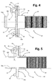
Figure 4 is a partial and schematic view in side elevation of a pipe device in accordance with a possible embodiment of the present invention; -
Figures 5 and6 are schematic cross-sectional views of the pipe device ofFigure 4 , taken along a vertical plane and a horizontal plane, respectively; -
Figure 7 is a partial and schematic perspective view of a cabinet of a water-conducting household appliance, with a pipe device in accordance with a possible embodiment of the present invention assembled thereon; -
Figure 8 is a schematic sectioned view of the appliance ofFigure 7 ; -
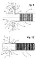
Figures 9 and 10 are schematic cross-sectional views of the appliance ofFigure 7 , taken along a vertical plane and a horizontal plane, respectively; -
Figure 11 is a view similar to that ofFigure 7 , with an external pipe of the household appliance coupled to a pipe device according to a possible embodiment of the present invention; -
Figure 12 is a partial and schematic view in side elevation of a pipe device in accordance with possible variant embodiments of the present invention; -
Figure 13 is a view similar to that ofFigure 11 , showing the pipe device ofFigure 12 ; and -
Figure 14 is a schematic sectioned view of the pipe device ofFigure 12 . - The reference to "an embodiment" within this description indicates that a particular configuration, structure, or characteristic described in relation to the embodiment is included in at least one embodiment. Therefore, phrases such as "in an embodiment", "in one embodiment" and the like, possibly present in different places of this description, do not necessarily refer to the same embodiment, but may instead refer to different embodiments. In addition, particular conformations, structures, or characteristics defined within this description can be combined in any suitable manner in one or more embodiments, which can even be different from the ones depicted. The numerical and spatial references (such as "upper", "lower", "front", "rear", etc.) used herein are for convenience only and therefore do not define the field of protection or the scope of the embodiments. In the figures, the same reference numerals are used to indicate elements that are similar or technically equivalent.
- It is also pointed out that in the following description only the elements useful for the understanding of the invention will be described, taking for granted that the appliance according to the invention comprises all the elements in itself known for its operation, such - for example - a user interface, a number of internal electrical components (e.g. a control board, one or more motors, a heating resistance, etc.), a number of internal water-conducting components (e.g. a washing agent dispenser, a wash-tub, etc), a number of mechanical components (e.g. a base, a front door, etc.).
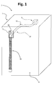
- Referring initially to
Figure 1 ,reference 1 designates as a whole a water-conducting electrical household appliance according to a possible embodiment of the present invention, such as a laundry-treatment machine or a dish-washing machine. Theappliance 1 has a cabinet, designated as a whole byreference 2, having a number of walls delimiting a space within which a plurality of functional components is housed. For instance, referring to the case of a laundry-treatment machine, the functional component may comprise a washtub, a laundry basket mounted to rotate within the wash-tub, a motor for driving the drum, a suspension arrangement for elastically supporting the washtub, a washing agent dispenser, a pump, electrical valves, a heating resistance, a control board, etcetera. InFigure 1 , only one of the internal functional components of the appliance has been represent, and more specifically a water-conducting component, designated as a whole by 3. In a preferred embodiment of the invention the water-conductingcomponent 3 is a device belonging to an arrangement for loading and/or circulating water with respect to a washtub of theappliance 1, such as a re-circulating pump or a drain pump, but it is not ruled out from the scope of the invention the case of a different components, such as an electric valve device, or an air break-device, or a washing agent dispenser, or a water-softener, etc.. - In one of the aforesaid walls of the
cabinet 2 an opening is defined, at which a sleeve member of a pipe device according to the present invention is located. InFigure 1 , the wall in question is the rear wall of the cabinet, designated by 4, whereas the relevant opening is designated by 5. The pipe device, which is designated by 10 as a whole, includes a flexible hose, designate by 20, and the cited sleeve member, designated by 30. A proximal end portion of thehose 20 is sealingly coupled to thesleeve member 30, whereas the distal end portion thereof is coupled to the water-conductingcomponent 3, which is preferably arranged within thecabinet 2 in a position remote from thewall 4. As is apparent, in this embodiment thehose 20 is designed to extend inside thecabinet 2, such that thedevice 10 can be defined as an internal pipe device for theappliance 1. - The way and the means used for connecting the distal end portion of the
hose 20 to thecomponent 3 may be of any known type and do not form part of the invention. In a preferred embodiment, thehose 20 is secured in one or more intermediate regions thereof (preferably in two intermediate regions) to the stationary structure of theappliance 1, for example to itscabinet 2, in order to confer the hose 20 a substantially predefined positioning and/or avoiding undesired displacement thereof. As securing means ties similar to those described in the patent applicationEP2082087A2 may be used advantageously. - Referring again to
Figure 1 ,reference 40 designates as a whole an external pipe of theappliance 1, i.e., a pipe designed to extend outside thecabinet 2. In one embodiment theexternal pipe 40 is a pipe for the discharging of a treatment fluid from theappliance 1, having a proximal end portion designed to be sealingly connected to thesleeve member 30 and the distal end portion designed to be connected to a sewer or the like. In one such embodiment, the water-conducting component might be a drain pump or a drain valve, preferably located in a lower region of the space defined by thecabinet 2. - In an embodiment, such as the one represented in
Figure 1 , theopening 5 is defined in a generally upper region of the wall 4: however, according to other possible embodiments, the opening 5 may be defined in a different position of height of thewall 4, such a lower region or an intermediate region of thewall 4. Additionally, it is not ruled out from the scope of the invention that thepipe device 10 belongs to an arrangement for the loading and/or the re-circulation of a treatment fluid with respect to a washtub of the appliance: in one such embodiment, for instance, the water-conducting component might be a valve device, or a re-circulating pump, or an air break-device, or a washing agent dispenser, or a water-softener, etc.. - A possible embodiment of a
pipe device 10 according to the invention is partially visible inFigure 2 . In this figure, theflexible hose 20 designed to extend inside thecabinet 2 is represented partially, the front of thesleeve member 30 being visible. In preferred embodiments of the invention, thehose 20 is a corrugated hose, preferably formed with a plastic material. In various embodiments the material forming the hose is a relatively rigid plastic material, the reduced thickness of the hose wall and the presence of the corrugations conferring in any case the required flexibility to the hose. Preferably the material forming the hose is a thermoplastic material, such as a polypropylene or a polypropylene-based material. - The
sleeve member 30 comprises aflange portion 31, designed to be secured at theopening 5, as well as two generally oppositetubular portions tubular portion 32 projects from the front side of theflange portion 31, whereas a secondtubular portions 33 projects from the rear side of theflange portion 31, these tubular portions being intended for extending outside and inside thecabinet 2, respectively. For this reason, hereinafter, theportion tubular portion 32 is designed to be sealingly connected with a proximal end of an external pipe, such as the tube designated by 40 inFigure 1 , whereas the internaltubular portion 33 is sealingly connected to the proximal end of thehose 20. - In accordance with the invention, the body of the
sleeve member 30, integrally defining in a single piece theflange portion 31 and the oppositetubular portions hose 20 which is embedded at least in a part of the plastic material that forms the internaltubular portion 33. This feature can be appreciated in particular inFigures 3 ,5 and6 , from which it is apparent how the inner and the outer side of the end portion of thehose 20 are surrounded by plastic material forming thesleeve member 30, and specifically a part of this material that forms the internaltubular portion 33. In the example represented the proximal end portion of thehose 20 extends axially within the plastic material of the body of thesleeve member 30 substantially as far as theflange portion 31, but it is not ruled out the case that the proximal end portion of thehose 20 further extends axially in the body of thesleeve member 30, so as to be embedded also in a part of the plastic material of theflange portion 31 or even in a part of the plastic material of the externaltubular portion 32. - In a preferred embodiment of the invention, the internal
tubular portion 33 is at least partly moulded over the proximal end portion of thehose 20. In this case it is preferable that the inner diameter and the outer diameter of thetubular portion 32 are smaller and greater than the inner and the outer diameter of the proximal end portion of the hose, respectively, as in the embodiment represented inFigures 3 ,5 and6 . - The feature that the proximal end of the
hose 20 is embedded at least in a part of the material of the internaltubular portion 33, in particular via moulding of the former over the latter, enables important advantages to be achieved. Firstly, a strong mechanical coupling and a safe watertight coupling are obtained between the proximal end of the hose and the sleeve, to advantage of the reliability of use of thepipe device 10. The quality of these mechanical and watertight couplings is improved in those embodiments in which thehose 20 is a corrugated hose, provided that the surface corrugations of the hose determine an improved "gripping" between the overmoulded material and the hose, as well as a sort of "labyrinth" between the coupled elements that prevents any possible liquid leakages. It is apparent that, in this way, the pipe device of the invention is intrinsically safe at least at the interface region between thetubular portion 33 and the proximal end of thehose 20, hence avoiding the cited risks of leakages towards the inside of the cabinet, wherein electrical components are present. - Preferably, the material or materials employed for moulding the
sleeve member 30, or at least the internal tubular portion thereof, is/are similar or chemically compatible with the material or materials that forms/form thehose 20, or at least the proximal end thereof, for example in order to allow a better sealing between the part in question. To this purpose, in possible embodiments of the invention, the material with which thesleeve member 30 is formed is the same as the material used for forminghose 20. In a preferred embodiment, for example, the material in question is a thermoplastic material, such as a polypropylene or a polypropylene-based material. - Additionally, the feature that the proximal end of the
hose 20 is embedded in the material of thesleeve member 30, in particular via overmoulding technique, noticeably simplifies the assembling of thepipe device 10, since no specific operations of coupling between the hose and the sleeve member are required. Additionally, the use of external tightening rings or the like are not required for securing thehose 20 to the internaltubular portion 33. - As is apparent for instance from
Figures 5 and6 , the internal duct of thesleeve member 30, designated by 30a, has two end stretches defined by thetubular portions flange portion 31. - Preferably, the inner surface of the
duct 30a is substantially smooth. Even more preferably, theduct 30a is an axial duct having a substantially frustoconical shape. This feature noticeably simplifies the (over)moulding operation, namely the extraction of thesleeve member 30 with the associated end portion of thehose 20 from the (over)moulding equipment. To this purpose, in various embodiments, thetubular portions sleeve member 31 are substantially coaxial. According to preferred embodiments, the secondtubular portions - Referring again to
Figures 2-6 , according to particularly advantageous embodiments of the invention, the externaltubular portion 32 has a substantially frustoconical outer shape - designated by 32a - at the end portion thereof which is remote from theflange portion 31. This feature greatly simplifies fitting of the proximal end of the external pipe on thetubular portion 32. Preferably, the frustoconicalouter shape 32a defines a intermediate outer step on the tubular portion 32: presence of this intermediate step, designated by 32b for instance inFigures 4-6 , may prove useful to ensure the correct action of external tightening rings or the like, possibly used for securing the proximal end region of the external pipe 40 (seeFigure 1 ) onto the externaltubular portion 32. - In accordance with the invention, the body made of substantially rigid material of the
sleeve member 30 also integrally defines fastening means at theflange portion 31, configured for quick-coupling with a peripheral edge of the opening 5 (seeFigure 1 ) defined in thewall 4 of thecabinet 2. Preferably, this fastening means are configured in such a way that theflange portion 31 can be coupled to the peripheral edge of theopening 5 without any additional fixing elements being required, such as screws or the like. In this manner, thesleeve member 30 can be secured in a simple and rapid manner to thewall 4, namely at theopening 5 thereof. Additionally, the feature that the fastening means are formed by the substantially rigid material of thesleeve member 30 assures a stable fixing of the latter to thewall 4, thereby reducing the risk of an accidental uncoupling of the sleeve member from theopening 5, due for instance to tractions or lateral thrusts exerted on theexternal pipe 40 and/or the proximal end thereof (Figure 1 ). - In a preferred embodiment of the invention the aforementioned fastening means are configured for snap-coupling with respect to the peripheral edge of the
opening 5. In the preferred embodiments of the invention the fastening means are defined at the front side of theflange portion 31 of the body of thesleeve member 30. - Referring again to
Figures 2-6 , in various embodiments the fastening means comprise at least one first coupling element and at least one second coupling element defined at generally opposite regions of theflange portion 31. In this way, the one-piece body of thesleeve member 30 can be safely secured at corresponding opposite regions of the edge of theopening 5, to improve its stability. To this purpose, according to preferred but not exclusive embodiments of the invention, theflange portion 31 and theopening 5 are substantially quadrilateral, or in any case have a substantially polygonal-shaped perimeter. - In various embodiments the first coupling element comprises a
first formation 34 of theflange portion 31, which defines a groove - designated by 34a inFigures 3-5 - adapted to be fitted over a corresponding first portion of the peripheral edge of theopening 5. Theformation 34 is preferably defined in the lower region of theflange portion 31. On the other hand, the second coupling element comprises asecond formation 35 of theflange portion 31, which is at least partially elastically deformable. Theformation 35 is preferably defined in the upper region of theflange portion 31. Thissecond formation 35 defines a recess or seat - designated by 35a inFigures 2-5 - adapted to be elastically engaged with a corresponding second portion of the peripheral edge of theopening 5. The cited first and second portions of the peripheral edge of theopening 5 are preferably opposite to each other: in one such embodiment, thegroove 34a and theseat 35a substantially face in opposite direction. Preferably, thetubular portion 32 protrudes from theflange portion 31 in a position intermediate to theformations - In various embodiments, as depicted in
Figures 2-5 , thesecond formation 35 is substantially U- or V-shaped formation and protrudes from the front side of theflange portion 31. Thisformation 35, configured substantially as a wing, has afirst portion 351, which branches off from the front side of theflange portion 31 and asecond portion 352, which is bent backwards, towards the same front side and has a free end at which the above citedseat 35a is defined. Preferably, in the front side of theflange portion 31 arecess 36 is also defined, substantially facing at least one portion of theformation 34, such as the aforementioned free end having theseat 35a. Presence of therecess 36, which in the illustrated embodiment is defined transversally in the front side of theflange portion 31, may prove useful to simplifies the operation of moulding of the body of thesleeve member 30, in order to define the free end of theformation 35, while enabling theflange portion 31 to have in any case arest region 37 for abutting against the inner side of thewall 4, as will be clear hereinafter. - Preferably, but not necessarily, the
flange portion 31 also defines strengthening ribs, at the front side and/or at the rear side thereof: examples of some of these ribs are designated by 38 in the figures. - In the preferred embodiments of the invention, the
flange portion 31 has perimetral dimensions greater that the perimetral dimensions of theopening 5 of thewall 4. In this way, thesleeve member 30 can be fitted through theopening 5 from the inside of thecabinet 2, in such a way that an annular peripheral region of theflange portion 31 faces a corresponding annular region of thewall 4 that surrounds theopening 5. This feature is also useful for safety reasons (particularly in connection with the fact that thesleeve member 30 as a whole, and namely itsflange portion 31, is substantially rigid), inasmuch as it prevents any elongated and thin objects - such as the blade of a knife - to be inserted between theflange portion 31 and the edge of theopening 5, from potentially reaching live electrical components located inside thecabinet 2. - In a preferred embodiment, as depicted in
Figure 2 , theflange portion 31 has a thinnerperipheral region 31 a and a thickercentral region 31 b, with the firsttubular portion 32 and the engagement means 34-35 which protrudes frontally from thiscentral region 31 b. Very preferably, the thickercentral region 31 b is adapted to be at least partially fitted into theopening 5 defined in thewall 4 of thecabinet 2, to improve stability of the assembly. In one such embodiment, advantageously, the thinnerperipheral region 31 a enable to define the aforesaid annular peripheral region of the flange portion that faces a corresponding annular region of thewall 4 surrounding theopening 5. - In
Figures 7 to 10 apipe device 10 according to the invention is shown in an installed condition at theopening 5 of thewall 4 of thecabinet 2, in an embodiment in which theflange portion 31 and theopening 5 are substantially quadrilateral. As is apparent, for instance fromFigures 8 and9 , the lower edge of theopening 5, designated by 5a, is inserted in theseat 34a of thelower formation 34, whereas theseat 35 of theupper formation 35 engages with the upper edge of theopening 5, designated by 5b. FromFigure 9 it is also apparent how, in a preferred embodiment, thethicker portion 31 b of theflange portion 31 is at least partially inserted into theopening 5, while the front of thethinner portion 31 a faces the inner side of the portion of thewall 4 which surrounds theopening 5. - Installation of the
device 10 is very quick and simple. To this purpose thedevice 10 is mounted from within thecabinet 2, in particular by manipulating theflange portion 31 into theopening 5 with a slightly inclined orientation, so as to fit thetransverse groove 34a defined by thelower formation 34 onto thelower edge 5a of theopening 5. Theflange portion 31 is then angularly moved (in a counter-clockwise direction, with reference toFigure 9 ), so as to make theupper formation 35 to pass through theopening 5. The relative dimensions of thegroove 34a and the wall 4 - in particular the width thereof - enable these two coupled elements to perform basically a hinge function. By the above angular movement, at least an upper end region of the front surface of theinclined portion 352 of theformation 35 is made to slide against thelower edge 5a of theopening 5, to be progressively bent in an elastic fashion, i.e., with the free end ofportion 352 which gets closer to theportion 351. When theflange portion 31 is almost in the vertical position, thelower edge 5b of theopening 5 reaches the step defined by theseat 35a of the upper formation 35: via the elastic reaction of theformation 35, theupper part 352 thereof tends to return to the initial, unstressed configuration (i.e., to widen with respect to portion 351), such that theseat 35a is engaged with theupper edge 5b of the opening with a substantially snap-in action, and with therest region 37 of theflange portion 31 that bears against the inner surface of thewall 4, in a position generally opposite to theseat 35. The assembling operator has a clear perception that the fixing of the sleeve member has occurred in a precise manner, in view of the snap-coupling, which typically results in an audible effect, like a "click". The mounting of thesleeve member 30 at theopening 5 is thus completed. The distal end portion of thehose 10 can be connected to the water-conducting components 3 (alternatively, the cited distal end can be connected to thecomponent 3 before coupling thesleeve member 30 to the opening 5). - It will be appreciated that, in the installed condition, the risks of possible leakages of fluid at the connection region between the
hose 20 and thesleeve member 30 is practically completely prevented, such that thedevice 10 results in being intrinsically safe. -
Figure 11 is a view similar to that ofFigure 7 , wherein anexternal pipe device 40 is sealingly coupled with the externaltubular portion 32 of thesleeve member 30. In this not-limiting example, theexternal pipe 40 includes aflexible hose 41, preferably but not necessarily a corrugated hose, having at the proximal end thereof aunion member 42 made of a relatively soft or elastic material, such as a rubber or a silicone. The union member may be, for example, moulded over the corresponding end region of thehose 41. In the example, theunion member 42 is an elbow union. - The proximal end region of the
pipe 40, as defined by thejoint member 42, is fitted onto thetubular portion 32 of thesleeve member 30, preferably exploiting the elasticity of the material forming the joint member. In this step, the frustoconicalouter shape 32a of the tubular portion 32 (see for instanceFigures 8-10 ) makes the operation in question easier. The mechanical and watertight coupling between thejoint member 42 and thetubular portion 32 is then ensured via an outer tightening ring, designated by 50, fitted over the portion of thejoint member 42 into which thetubular portion 32 is inserted. After fixing of thisring 50, presence of the outerintermediate step 32b of the tubular portion (see for instanceFigures 8-10 ) prevents thesame ring 50 to slide away from the position where it ensures the mechanical and watertight coupling. - The
pipe device 10 according to the invention is also simple and cheap to produce. To this purpose, thehose 20 may be produced in any known manner, whereas thesleeve member 30, and the sealed coupling thereof with the proximal end of thehose 20, may be obtained via over-moulding of the plastic material that is to form the body of the sleeve member. More specifically, part of the material to form thesleeve member 30, and namely at least part of the material designed to form the internaltubular portion 33, is moulded over the proximal end portion of thehose 20. Via the same (over)moulding operation, in the body of thesleeve member 30 the fastening means 34-35 are also defined. - From the above description, the characteristics of the present invention are clear, as are its advantages, mainly represented by the simplicity of producing and installing the pipe device proposed, from its low cost, its reliability and its high flexibility of use and configuration.
- It is clear to the person skilled in the art that numerous variants are possible of devices and methods described as an example, without thereby departing from the scope of the invention as defined by the attached claims.
- For instance,
Figures 12, 13 and14 show possible variants embodiments of a pipe device according to the present invention. - In a variant embodiment, the
device 10 integrates means for checking or verifying the correctness of the coupling condition between the fastening means and the peripheral edge of the corresponding opening defined in the wall of the cabinet. Preferably, this checking means are integrated in the fastening means of the sleeve member, very preferably in the part thereof that perform the snap-in function. In the preferred embodiment also this checking means are integrally defined in the body of the sleeve member. The cited checking means are optionally provided in thedevice 10, if it is desired to give the assembling operator a further way to verify the coupling correctness, in addition to the above mentioned audible effect (a "click") inherent in a snap-in coupling. - In the embodiment exemplified in
Figure 12 the fastening means represented by theupper formation 35 includes a manuallyoperable projection 35b, basically configured as a small lever, protruding from theformation 35 in a direction generally opposite to theseat 35. More specifically, in the exemplary embodiment, theprojection 35b protrudes from the outer side of theupper portion 352 of theformation 35. Preferably, theprojection 35b has a reduced height, or in any case a height such that - during installation - theprojection 35b does not hinder passage of theupper formation 35 through theopening 5 and the sliding of the end region of the front surface of theportion 352 against the upper edge of theopening 5. - The installed condition of the pipe device of
Figure 12 is shown partially and schematically inFigure 13 . The modalities of installation of thedevice 10 ofFigure 12 are the same as already described above. As a rule the assembling operator perceives the "click" confirming correctness of the snap-in coupling, i.e., of the elastic engagement of theseat 35a of theformation 35 with the upper edge of the opening with 5. However, if for any reasons the operator does not hear the "click" (for instance due to environmental noise) or desires in any case to verify the quality of the coupling, he has simply to exert a force on theprojection 35b, for example in the direction indicated by the arrow "A" ofFigure 12 . In this case, if the snap-in coupling occurred correctly, the thrust exerted on theprojection 35b in the direction A would not cause any consequence, due to the interference between the step defined by theseat 35 with the front side of thewall 4. By contrast, if the snap-in coupling did not occurred, the thrust exerted on theprojection 35b in the direction A would cause an angular back-movement of thesleeve member 30 as a whole, due to the "hinge effect" determined by the coupled condition between theseat 34a of thelower formation 34 with the lower edge of theopening 5. - As an alternative, the operator may exert a thrust in the direction indicated by the arrow "B" of
Figure 12 . Also in this case, if the snap-in coupling occurred correctly, the thrust exerted on theprojection 35b in the direction B would not cause any outward flexure of theportion 352 of theformation 35, due to the interference between theseat 35 with the upper edge of theopening 5. By contrast, if the snap-in coupling did not occurred, the thrust exerted on theprojection 35b in the direction B would cause an outward flexure of theportion 352, perceivable by the assembling operator. -
Figures 12, 13 and14 also show a possible further variant embodiment, according to which the pipe device of the invention is further provided with venting means. Preferably, this venting means are defined by a fitting or the like protruding from thetubular portion 33 of thesleeve member 30. In the preferred embodiment also this venting means are integrally defined in the body of the sleeve member. - In the example of
Figure 12 , the venting means, designated by 33a, are configured as a tubular fitting protruding laterally from thetubular portion 33, but it is not ruled out the case of a fitting 33a protruding from the upper or the lower part of theportion 33. The fitting 33a is preferably configured for coupling with the proximal end portion of a pipe, such as a breather pipe designated by 60 inFigures 13 and14 . The distal end of thisbreather pipe 60 may be connected with the washtub of the appliance or with a different water-conducting component thereof, for instance a washing agent dispenser. The fitting 33a, and thepossible pipe 60 associated thereto, may be provided for bringing the inside of thehose 30 at the atmospheric pressure. - Production of the
pipe device 10 including the venting means 33a occurs in the same way as discussed above, i.e., by moulding the body of thesleeve member 30 over the proximal end portion of thehose 20, in such a way that this proximal end portion is embedded to some extent into the material of thetubular portion 33. It will be appreciated that, in this way the internal duct of the fitting 33a is sealingly closed at the inner end thereof, due to the presence of a portion of the wall of thehose 20 which is embedded in the tubular portion 33 (as schematically depicted inFigure 12 ), and/or due to the presence of a relatively thin layer of the plastic material extending over the hose wall following overmoulding. To this purpose, however, it is to be noted that the fitting 33a is provided on thesleeve member 30 for optional use only, and namely with the fitting 33a to be actually used only on certain type of appliances, for instance appliances which require the inside of thetube 20 be brought to atmospheric pressure. Hence, when thedevice 10 has to be used in such instances, a specific operation of drilling or piercing will be carried out during the manufacturing or assembling step, to put the internal duct of the fitting 33a in direct communication with the inside of thehose 20. This operation may be performed, for instance, by inserting a suitable tool within the duct of the fitting 33a, to form a hole through the corresponding portion of the hose wall and the adjoining layer or layers of the overmoulded plastic material. A condition of this kind, in which the fitting 33a is open towards the inside of thehose 20, is represented inFigure 14 . By contrast, when thedevice 10 has to be installed on appliances which do not require the use of a vent fitting, the above drilling or piercing operation has not to be performed. - Clearly, the two variants described in connection with
Figure 12-14 are not functionally interrelated, such that thedevice 10 might be also provided with theprojection 35b only, or with thevent 33a only.
Claims (15)
- A pipe device for a water-conducting electrical household appliance (1), in particular a laundry-treatment machine or a dish-washing machine, comprising:- a flexible hose (20), designed to extend inside the cabinet (2) of a water-conducting electrical household appliance (1), and- a sleeve member (30) including a flange portion (31), designed to be secured at an opening (5) defined in a wall (4) of the cabinet (2) of the water-conducting electrical household appliance (1), the sleeve member (30) also including a first tubular portion (32), to which an end portion of an external pipe (40) designed to extend outside the cabinet (2) of the water-conducting household appliance (1) is connectable, and a second tubular portion (33) for connection to a proximal end portion of the hose (20),wherein the first and the second tubular portions (32, 33) project from a front side and a rear side of the flange portion (31), respectively, the first and the second tubular portions (32, 33) being designed to extend outside and inside the cabinet (2) of the water-conducting household appliance (1), respectively,
the pipe device (10) being characterized in that the sleeve member (31) has a body made of a substantially rigid plastic material, with the proximal end portion of the hose (20) which is embedded at least in the plastic material that forms the second tubular portion (33), the body made of substantially rigid plastic material also integrally defining fastening means (34, 35) at said flange portion (31), configured for quick-coupling with a peripheral edge (5a, 5b) of the opening (5) defined in the wall (4) of the cabinet (1). - The pipe device according to claim 1, wherein the second tubular portion (33) of the sleeve member (30) is at least partly moulded over the proximal end portion of the hose (20).
- The pipe device according to claim 1 or claim 2, wherein the fastening means (34, 35) are defined at the front side of the flange portion (31) of body of the sleeve member (30).
- The pipe device according to any one of the preceding claims, wherein the fastening means (34, 35) are configured for snap-coupling with the peripheral edge (5a, 5b) of the opening (5) defined in the wall (4) of the cabinet (1).
- The pipe device according to claim 4, wherein the fastening means (34, 35) comprise at least one first coupling element (34) and at least one second coupling element (35) defined at generally opposite regions of the flange portion (31) of body of the sleeve member (30).
- The pipe device according to claim 5, wherein- the first coupling element comprises a first formation (34) of the flange portion (31) which defines a groove (34a) adapted to be fitted over a corresponding portion (5a) of the peripheral edge (5a, 5b) of the opening (5) defined in the wall (4) of the cabinet (1);- the second coupling element comprises a second formation (35) of the flange portion (31) that is at least partially elastically deformable, the second formation (35) defining a seat (35a) adapted to be elastically engaged with a corresponding portion (5b) of the peripheral edge (5a, 5b) of the opening (5) defined in the wall (4) of the cabinet (1).
- The pipe device according to claim 6, wherein the second formation (35) comprises a substantially U- or V-shaped formation projecting from the front side of the flange portion (31) and having a free end at which said seat (35) is defined, the front side of the flange portion (31) preferably defining a recess (36) facing at least part of the second formation (35).
- The pipe device according to any one of the preceding claims, wherein the flange portion (31) has a thinner peripheral region (31 a) and a thicker central region (31 b), the first tubular portion (32) and the fastening means (34, 35) protruding from the central thicker region (31 b), the thicker central region (31 b) being preferably adapted to be at least partially fitted into the opening (5) defined in the wall (4) of the cabinet (1).
- The pipe device according to any one of claims 1-8, wherein the hose (20) is a corrugated hose.
- The pipe device according to any one of claims 1-9, wherein- the first and the second tubular portions (32, 33) of the sleeve member (30) are substantially coaxial; and /or- the first and the second tubular portions (32, 33) of the sleeve member (30) are substantially straight tubular portions; and/or- the body made of substantially rigid plastic material defines an axial passage (30a) of the sleeve member (30) which has a substantially frustoconical shape; and/or- the first tubular portion (32) has a substantially frustoconical outer shape (32a) at the end portion thereof remote from the flange portion (31), the frustoconical shape defining an intermediate outer step (32b) of the first tubular portion (32); and/or- the second tubular portion (33) has an inner diameter and an outer diameter which are smaller and greater, respectively, than an inner diameter and an outer diameter of the proximal end portion of the hose (20); and/or- the sleeve member (30) also integrates means (35b) for checking or verifying correctness of the coupling condition between the fastening means (34, 35) and the peripheral edge (5a, 5b) of the opening (5) defined in the wall (4) of the cabinet (2), the checking means (35b) being preferably integrated in the fastening means (34, 35), very preferably in a part thereof (35) that perform a snap-in function; and/or- the sleeve member 30 also comprises venting means (33a), preferably configured as a fitting protruding from the second tubular portion (33), the fitting being very preferably designed for coupling with the proximal end portion of a further pipe (60) designed to extend with the cabined (2) of the appliance (1).
- A water-conducting electrical household appliance having a cabinet (2) for housing a plurality of functional components, among which at least one water-conducting component (3), the cabinet (2) having a wall (4) in which an opening (5) is defined, the household appliance (1) further comprising a pipe device (10) according to one or more of the preceding claims, wherein a distal end portion of the hose (20) of the pipe device (10) is connected to said at least one water-conducting component (3).
- The water-conducting household appliance according to claim 11, wherein the flange portion (31) of the sleeve member (30) has perimetral dimensions greater that the perimetral dimensions of the opening (5) of the wall (4) of the cabinet (1), the flange portion (31) and the opening (5) being preferably substantially quadrilateral.
- The water-conducting household appliance according to claim 12, wherein the sleeve member (30) is at least partially fitted through the opening (5) from the inside of the cabinet (2), in such a way that an annular peripheral region of the flange portion faces a corresponding annular region of the wall (4) of the cabinet (1) that surrounds the opening (5).
- The water conducting household appliance according to any one of claim 11-13, further comprising an external pipe (40) having a proximal end portion (42) which is sealingly coupled to the first tubular portion (32) of the sleeve member (30), the proximal end portion (42) of the external pipe (40) being fitted over the first tubular portion (32).
- A method for producing a water-conducting electrical household appliance, comprising the steps of:i) providing a cabinet (2) having a number of walls delimiting a space for accommodating a number of functional components of the water-conducting electrical household appliance (1), among which at least one water-conducting component (3), in one of said wall (4) an opening (5) being defined;ii) providing a hose (20) designed to extend inside the cabinet (2), the hose (20) having a distal end portion designed for connection to the at least one water-conducting component (3),iii) providing a sleeve member (30) including a flange portion (31), a first tubular portion (32) and second tubular portion (33), the first and the second tubular portions (32, 33) protruding from a front side and a rear side of the flange portion (31), respectively,iv) sealingly coupling a proximal end portion of the hose (20) to the second tubular portion (33) of the sleeve member (30),v) securing the flange portion (31) of the sleeve member (30) at the opening (5) defined in said wall (4) of the cabinet (2), in such a way that the first and the second tubular portions (32, 33) extend inside and outside the cabinet (2), respectively,wherein steps iii) and iv) comprises the operation of forming the sleeve member (30) as a body made of a substantially rigid plastic material, with the second tubular portion (33) which is at least partly moulded over the proximal end portion of the hose (20), the body made of a substantially rigid plastic material also integrally defining fastening means (34, 35) at said flange portion (31), configured for quick-coupling with a peripheral edge (5a, 5b) of the opening (5) defined in said wall (4) of the cabinet (1),
and wherein step v) comprised securing the flange portion (31) of the sleeve member (30) at said opening (5) by snap-coupling said fastening means (34, 35) with said peripheral edge (5a, 5b) of said opening (5).
Priority Applications (1)
| Application Number | Priority Date | Filing Date | Title |
|---|---|---|---|
| EP15171478.9A EP3103913B1 (en) | 2015-06-10 | 2015-06-10 | A pipe device for a water-conducting electrical household appliance |
Applications Claiming Priority (1)
| Application Number | Priority Date | Filing Date | Title |
|---|---|---|---|
| EP15171478.9A EP3103913B1 (en) | 2015-06-10 | 2015-06-10 | A pipe device for a water-conducting electrical household appliance |
Publications (2)
| Publication Number | Publication Date |
|---|---|
| EP3103913A1 true EP3103913A1 (en) | 2016-12-14 |
| EP3103913B1 EP3103913B1 (en) | 2018-03-21 |
Family
ID=53397868
Family Applications (1)
| Application Number | Title | Priority Date | Filing Date |
|---|---|---|---|
| EP15171478.9A Active EP3103913B1 (en) | 2015-06-10 | 2015-06-10 | A pipe device for a water-conducting electrical household appliance |
Country Status (1)
| Country | Link |
|---|---|
| EP (1) | EP3103913B1 (en) |
Cited By (1)
| Publication number | Priority date | Publication date | Assignee | Title |
|---|---|---|---|---|
| WO2022167089A1 (en) * | 2021-02-05 | 2022-08-11 | Electrolux Appliances Aktiebolag | Laundry treating machine equipped with a holding system for a draining line |
Citations (5)
| Publication number | Priority date | Publication date | Assignee | Title |
|---|---|---|---|---|
| US4870988A (en) * | 1987-10-07 | 1989-10-03 | Whirlpool Corporation | One-piece drain hose OFR an automatic washer |
| EP0335454A2 (en) * | 1988-03-29 | 1989-10-04 | Whirlpool Europe B.V. | Drainage device particularly for washing machines, for preventing water leakage during extraction of the filtration member |
| DE19548477A1 (en) * | 1994-12-23 | 1996-06-27 | Elbi Int Spa | Appts. for hydraulic and electrical connecting water supply device to washing machine |
| EP2082087A2 (en) | 2006-10-13 | 2009-07-29 | Indesit Company, S.P.A. | Front-loading laundry washing machine |
| US20120255329A1 (en) * | 2011-04-06 | 2012-10-11 | Bsh Home Appliances Corporation | Drain hose for a washer |
Family Cites Families (4)
| Publication number | Priority date | Publication date | Assignee | Title |
|---|---|---|---|---|
| JPH051484U (en) * | 1991-06-14 | 1993-01-14 | 株式会社東芝 | Drain hose attachment device for washing machine |
| JP3799785B2 (en) * | 1997-11-21 | 2006-07-19 | 松下電器産業株式会社 | Washing machine drain hose |
| JP2002306892A (en) * | 2001-04-10 | 2002-10-22 | Tigers Polymer Corp | Internal draining hose for washing machine |
| ES2356105T3 (en) * | 2008-05-27 | 2011-04-04 | Bonferraro S.P.A. | WASHING DEVICE FOR WASHERS, WITH AIR VALVE, CORRESPONDING MANUFACTURING AND WASHING METHOD THAT INCLUDES SUCH DEVICE. |
-
2015
- 2015-06-10 EP EP15171478.9A patent/EP3103913B1/en active Active
Patent Citations (5)
| Publication number | Priority date | Publication date | Assignee | Title |
|---|---|---|---|---|
| US4870988A (en) * | 1987-10-07 | 1989-10-03 | Whirlpool Corporation | One-piece drain hose OFR an automatic washer |
| EP0335454A2 (en) * | 1988-03-29 | 1989-10-04 | Whirlpool Europe B.V. | Drainage device particularly for washing machines, for preventing water leakage during extraction of the filtration member |
| DE19548477A1 (en) * | 1994-12-23 | 1996-06-27 | Elbi Int Spa | Appts. for hydraulic and electrical connecting water supply device to washing machine |
| EP2082087A2 (en) | 2006-10-13 | 2009-07-29 | Indesit Company, S.P.A. | Front-loading laundry washing machine |
| US20120255329A1 (en) * | 2011-04-06 | 2012-10-11 | Bsh Home Appliances Corporation | Drain hose for a washer |
Cited By (1)
| Publication number | Priority date | Publication date | Assignee | Title |
|---|---|---|---|---|
| WO2022167089A1 (en) * | 2021-02-05 | 2022-08-11 | Electrolux Appliances Aktiebolag | Laundry treating machine equipped with a holding system for a draining line |
Also Published As
| Publication number | Publication date |
|---|---|
| EP3103913B1 (en) | 2018-03-21 |
Similar Documents
| Publication | Publication Date | Title |
|---|---|---|
| US7677610B2 (en) | Connection and joint piece for well tubes | |
| US8459064B2 (en) | Water-conducting household appliance, in particular a dishwasher or washing machine | |
| RU2582951C2 (en) | Device for protection of household appliances from fluid leaks | |
| EP3103913B1 (en) | A pipe device for a water-conducting electrical household appliance | |
| KR20140048112A (en) | Anti-flooding safety device for household appliances, in particular washing machines | |
| CN110137895B (en) | Grommet, electronic component, and method of forming grommet | |
| US20140144521A1 (en) | Safety device against fluid leaks for household appliances | |
| EP1327812A2 (en) | Corrugated tubing assembly with integrated quick connector | |
| EP2128326B1 (en) | Washer drain with valved vent, relevant manufacturing method and washer comprising such drain | |
| CN106983438B (en) | Device for connecting electrical connectors | |
| US8122548B2 (en) | Mounting and method for mounting a water vacuum break | |
| CN109994972B (en) | Assembly for cable feed-through | |
| US20130093180A1 (en) | Detachable plug connection | |
| JP2016000938A (en) | Drain plug device | |
| KR20080000196A (en) | Cap for terminal junction point | |
| CN110709630B (en) | Fixed seal ring | |
| JP7272650B2 (en) | Operating device | |
| US10738930B2 (en) | Coupling arrangement for a domestic appliance, a device for a domestic appliance, and a domestic appliance | |
| KR20160133290A (en) | Pipe for connecting drain pipe | |
| EP3135179A1 (en) | Household appliance comprising a gasket | |
| CN113013658B (en) | Electrical box protruding from support for fixing | |
| KR200490524Y1 (en) | Cable protection structure for dish washer | |
| SE530636C2 (en) | Transmission for water hoses | |
| EP3090090B1 (en) | Household washing appliance | |
| WO2014195913A1 (en) | A hydraulic outlet adapter |
Legal Events
| Date | Code | Title | Description |
|---|---|---|---|
| PUAI | Public reference made under article 153(3) epc to a published international application that has entered the european phase |
Free format text: ORIGINAL CODE: 0009012 |
|
| STAA | Information on the status of an ep patent application or granted ep patent |
Free format text: STATUS: THE APPLICATION HAS BEEN PUBLISHED |
|
| AK | Designated contracting states |
Kind code of ref document: A1 Designated state(s): AL AT BE BG CH CY CZ DE DK EE ES FI FR GB GR HR HU IE IS IT LI LT LU LV MC MK MT NL NO PL PT RO RS SE SI SK SM TR |
|
| AX | Request for extension of the european patent |
Extension state: BA ME |
|
| STAA | Information on the status of an ep patent application or granted ep patent |
Free format text: STATUS: REQUEST FOR EXAMINATION WAS MADE |
|
| 17P | Request for examination filed |
Effective date: 20170217 |
|
| RBV | Designated contracting states (corrected) |
Designated state(s): AL AT BE BG CH CY CZ DE DK EE ES FI FR GB GR HR HU IE IS IT LI LT LU LV MC MK MT NL NO PL PT RO RS SE SI SK SM TR |
|
| STAA | Information on the status of an ep patent application or granted ep patent |
Free format text: STATUS: EXAMINATION IS IN PROGRESS |
|
| 17Q | First examination report despatched |
Effective date: 20170510 |
|
| GRAP | Despatch of communication of intention to grant a patent |
Free format text: ORIGINAL CODE: EPIDOSNIGR1 |
|
| STAA | Information on the status of an ep patent application or granted ep patent |
Free format text: STATUS: GRANT OF PATENT IS INTENDED |
|
| INTG | Intention to grant announced |
Effective date: 20180105 |
|
| GRAS | Grant fee paid |
Free format text: ORIGINAL CODE: EPIDOSNIGR3 |
|
| GRAA | (expected) grant |
Free format text: ORIGINAL CODE: 0009210 |
|
| STAA | Information on the status of an ep patent application or granted ep patent |
Free format text: STATUS: THE PATENT HAS BEEN GRANTED |
|
| GRAT | Correction requested after decision to grant or after decision to maintain patent in amended form |
Free format text: ORIGINAL CODE: EPIDOSNCDEC |
|
| AK | Designated contracting states |
Kind code of ref document: B1 Designated state(s): AL AT BE BG CH CY CZ DE DK EE ES FI FR GB GR HR HU IE IS IT LI LT LU LV MC MK MT NL NO PL PT RO RS SE SI SK SM TR |
|
| REG | Reference to a national code |
Ref country code: GB Ref legal event code: FG4D |
|
| REG | Reference to a national code |
Ref country code: CH Ref legal event code: EP |
|
| REG | Reference to a national code |
Ref country code: AT Ref legal event code: REF Ref document number: 981220 Country of ref document: AT Kind code of ref document: T Effective date: 20180415 |
|
| REG | Reference to a national code |
Ref country code: IE Ref legal event code: FG4D |
|
| REG | Reference to a national code |
Ref country code: DE Ref legal event code: R096 Ref document number: 602015008986 Country of ref document: DE |
|
| REG | Reference to a national code |
Ref country code: FR Ref legal event code: PLFP Year of fee payment: 4 |
|
| REG | Reference to a national code |
Ref country code: NL Ref legal event code: MP Effective date: 20180321 |
|
| PG25 | Lapsed in a contracting state [announced via postgrant information from national office to epo] |
Ref country code: HR Free format text: LAPSE BECAUSE OF FAILURE TO SUBMIT A TRANSLATION OF THE DESCRIPTION OR TO PAY THE FEE WITHIN THE PRESCRIBED TIME-LIMIT Effective date: 20180321 Ref country code: CY Free format text: LAPSE BECAUSE OF FAILURE TO SUBMIT A TRANSLATION OF THE DESCRIPTION OR TO PAY THE FEE WITHIN THE PRESCRIBED TIME-LIMIT Effective date: 20180321 Ref country code: LT Free format text: LAPSE BECAUSE OF FAILURE TO SUBMIT A TRANSLATION OF THE DESCRIPTION OR TO PAY THE FEE WITHIN THE PRESCRIBED TIME-LIMIT Effective date: 20180321 Ref country code: FI Free format text: LAPSE BECAUSE OF FAILURE TO SUBMIT A TRANSLATION OF THE DESCRIPTION OR TO PAY THE FEE WITHIN THE PRESCRIBED TIME-LIMIT Effective date: 20180321 Ref country code: NO Free format text: LAPSE BECAUSE OF FAILURE TO SUBMIT A TRANSLATION OF THE DESCRIPTION OR TO PAY THE FEE WITHIN THE PRESCRIBED TIME-LIMIT Effective date: 20180621 |
|
| REG | Reference to a national code |
Ref country code: LT Ref legal event code: MG4D |
|
| REG | Reference to a national code |
Ref country code: AT Ref legal event code: MK05 Ref document number: 981220 Country of ref document: AT Kind code of ref document: T Effective date: 20180321 |
|
| PG25 | Lapsed in a contracting state [announced via postgrant information from national office to epo] |
Ref country code: RS Free format text: LAPSE BECAUSE OF FAILURE TO SUBMIT A TRANSLATION OF THE DESCRIPTION OR TO PAY THE FEE WITHIN THE PRESCRIBED TIME-LIMIT Effective date: 20180321 Ref country code: GR Free format text: LAPSE BECAUSE OF FAILURE TO SUBMIT A TRANSLATION OF THE DESCRIPTION OR TO PAY THE FEE WITHIN THE PRESCRIBED TIME-LIMIT Effective date: 20180622 Ref country code: BG Free format text: LAPSE BECAUSE OF FAILURE TO SUBMIT A TRANSLATION OF THE DESCRIPTION OR TO PAY THE FEE WITHIN THE PRESCRIBED TIME-LIMIT Effective date: 20180621 Ref country code: SE Free format text: LAPSE BECAUSE OF FAILURE TO SUBMIT A TRANSLATION OF THE DESCRIPTION OR TO PAY THE FEE WITHIN THE PRESCRIBED TIME-LIMIT Effective date: 20180321 Ref country code: LV Free format text: LAPSE BECAUSE OF FAILURE TO SUBMIT A TRANSLATION OF THE DESCRIPTION OR TO PAY THE FEE WITHIN THE PRESCRIBED TIME-LIMIT Effective date: 20180321 |
|
| PG25 | Lapsed in a contracting state [announced via postgrant information from national office to epo] |
Ref country code: ES Free format text: LAPSE BECAUSE OF FAILURE TO SUBMIT A TRANSLATION OF THE DESCRIPTION OR TO PAY THE FEE WITHIN THE PRESCRIBED TIME-LIMIT Effective date: 20180321 Ref country code: NL Free format text: LAPSE BECAUSE OF FAILURE TO SUBMIT A TRANSLATION OF THE DESCRIPTION OR TO PAY THE FEE WITHIN THE PRESCRIBED TIME-LIMIT Effective date: 20180321 Ref country code: AL Free format text: LAPSE BECAUSE OF FAILURE TO SUBMIT A TRANSLATION OF THE DESCRIPTION OR TO PAY THE FEE WITHIN THE PRESCRIBED TIME-LIMIT Effective date: 20180321 Ref country code: PL Free format text: LAPSE BECAUSE OF FAILURE TO SUBMIT A TRANSLATION OF THE DESCRIPTION OR TO PAY THE FEE WITHIN THE PRESCRIBED TIME-LIMIT Effective date: 20180321 Ref country code: RO Free format text: LAPSE BECAUSE OF FAILURE TO SUBMIT A TRANSLATION OF THE DESCRIPTION OR TO PAY THE FEE WITHIN THE PRESCRIBED TIME-LIMIT Effective date: 20180321 Ref country code: EE Free format text: LAPSE BECAUSE OF FAILURE TO SUBMIT A TRANSLATION OF THE DESCRIPTION OR TO PAY THE FEE WITHIN THE PRESCRIBED TIME-LIMIT Effective date: 20180321 |
|
| PG25 | Lapsed in a contracting state [announced via postgrant information from national office to epo] |
Ref country code: SK Free format text: LAPSE BECAUSE OF FAILURE TO SUBMIT A TRANSLATION OF THE DESCRIPTION OR TO PAY THE FEE WITHIN THE PRESCRIBED TIME-LIMIT Effective date: 20180321 Ref country code: CZ Free format text: LAPSE BECAUSE OF FAILURE TO SUBMIT A TRANSLATION OF THE DESCRIPTION OR TO PAY THE FEE WITHIN THE PRESCRIBED TIME-LIMIT Effective date: 20180321 Ref country code: SM Free format text: LAPSE BECAUSE OF FAILURE TO SUBMIT A TRANSLATION OF THE DESCRIPTION OR TO PAY THE FEE WITHIN THE PRESCRIBED TIME-LIMIT Effective date: 20180321 Ref country code: AT Free format text: LAPSE BECAUSE OF FAILURE TO SUBMIT A TRANSLATION OF THE DESCRIPTION OR TO PAY THE FEE WITHIN THE PRESCRIBED TIME-LIMIT Effective date: 20180321 |
|
| PG25 | Lapsed in a contracting state [announced via postgrant information from national office to epo] |
Ref country code: PT Free format text: LAPSE BECAUSE OF FAILURE TO SUBMIT A TRANSLATION OF THE DESCRIPTION OR TO PAY THE FEE WITHIN THE PRESCRIBED TIME-LIMIT Effective date: 20180723 |
|
| REG | Reference to a national code |
Ref country code: DE Ref legal event code: R097 Ref document number: 602015008986 Country of ref document: DE |
|
| PLBE | No opposition filed within time limit |
Free format text: ORIGINAL CODE: 0009261 |
|
| STAA | Information on the status of an ep patent application or granted ep patent |
Free format text: STATUS: NO OPPOSITION FILED WITHIN TIME LIMIT |
|
| PG25 | Lapsed in a contracting state [announced via postgrant information from national office to epo] |
Ref country code: DK Free format text: LAPSE BECAUSE OF FAILURE TO SUBMIT A TRANSLATION OF THE DESCRIPTION OR TO PAY THE FEE WITHIN THE PRESCRIBED TIME-LIMIT Effective date: 20180321 |
|
| REG | Reference to a national code |
Ref country code: CH Ref legal event code: PL |
|
| 26N | No opposition filed |
Effective date: 20190102 |
|
| REG | Reference to a national code |
Ref country code: BE Ref legal event code: MM Effective date: 20180630 |
|
| REG | Reference to a national code |
Ref country code: IE Ref legal event code: MM4A |
|
| PG25 | Lapsed in a contracting state [announced via postgrant information from national office to epo] |
Ref country code: MC Free format text: LAPSE BECAUSE OF FAILURE TO SUBMIT A TRANSLATION OF THE DESCRIPTION OR TO PAY THE FEE WITHIN THE PRESCRIBED TIME-LIMIT Effective date: 20180321 Ref country code: LU Free format text: LAPSE BECAUSE OF NON-PAYMENT OF DUE FEES Effective date: 20180610 |
|
| PG25 | Lapsed in a contracting state [announced via postgrant information from national office to epo] |
Ref country code: CH Free format text: LAPSE BECAUSE OF NON-PAYMENT OF DUE FEES Effective date: 20180630 Ref country code: LI Free format text: LAPSE BECAUSE OF NON-PAYMENT OF DUE FEES Effective date: 20180630 Ref country code: IE Free format text: LAPSE BECAUSE OF NON-PAYMENT OF DUE FEES Effective date: 20180610 |
|
| PG25 | Lapsed in a contracting state [announced via postgrant information from national office to epo] |
Ref country code: BE Free format text: LAPSE BECAUSE OF NON-PAYMENT OF DUE FEES Effective date: 20180630 Ref country code: SI Free format text: LAPSE BECAUSE OF FAILURE TO SUBMIT A TRANSLATION OF THE DESCRIPTION OR TO PAY THE FEE WITHIN THE PRESCRIBED TIME-LIMIT Effective date: 20180321 |
|
| PG25 | Lapsed in a contracting state [announced via postgrant information from national office to epo] |
Ref country code: MT Free format text: LAPSE BECAUSE OF NON-PAYMENT OF DUE FEES Effective date: 20180610 |
|
| PG25 | Lapsed in a contracting state [announced via postgrant information from national office to epo] |
Ref country code: TR Free format text: LAPSE BECAUSE OF FAILURE TO SUBMIT A TRANSLATION OF THE DESCRIPTION OR TO PAY THE FEE WITHIN THE PRESCRIBED TIME-LIMIT Effective date: 20180321 |
|
| PG25 | Lapsed in a contracting state [announced via postgrant information from national office to epo] |
Ref country code: MK Free format text: LAPSE BECAUSE OF NON-PAYMENT OF DUE FEES Effective date: 20180321 Ref country code: HU Free format text: LAPSE BECAUSE OF FAILURE TO SUBMIT A TRANSLATION OF THE DESCRIPTION OR TO PAY THE FEE WITHIN THE PRESCRIBED TIME-LIMIT; INVALID AB INITIO Effective date: 20150610 |
|
| PG25 | Lapsed in a contracting state [announced via postgrant information from national office to epo] |
Ref country code: IS Free format text: LAPSE BECAUSE OF FAILURE TO SUBMIT A TRANSLATION OF THE DESCRIPTION OR TO PAY THE FEE WITHIN THE PRESCRIBED TIME-LIMIT Effective date: 20180721 |
|
| REG | Reference to a national code |
Ref country code: FR Ref legal event code: PLFP Year of fee payment: 9 |
|
| P01 | Opt-out of the competence of the unified patent court (upc) registered |
Effective date: 20230522 |
|
| PGFP | Annual fee paid to national office [announced via postgrant information from national office to epo] |
Ref country code: IT Payment date: 20230510 Year of fee payment: 9 Ref country code: FR Payment date: 20230411 Year of fee payment: 9 Ref country code: DE Payment date: 20230418 Year of fee payment: 9 |
|
| PGFP | Annual fee paid to national office [announced via postgrant information from national office to epo] |
Ref country code: GB Payment date: 20230420 Year of fee payment: 9 |