EP3103596A1 - Method for loading load carriers and loading/unloading station - Google Patents
Method for loading load carriers and loading/unloading station Download PDFInfo
- Publication number
- EP3103596A1 EP3103596A1 EP15171273.4A EP15171273A EP3103596A1 EP 3103596 A1 EP3103596 A1 EP 3103596A1 EP 15171273 A EP15171273 A EP 15171273A EP 3103596 A1 EP3103596 A1 EP 3103596A1
- Authority
- EP
- European Patent Office
- Prior art keywords
- loading
- carrier
- unloading station
- handling device
- charge carrier
- Prior art date
- Legal status (The legal status is an assumption and is not a legal conclusion. Google has not performed a legal analysis and makes no representation as to the accuracy of the status listed.)
- Ceased
Links
Images


Classifications
-
- B—PERFORMING OPERATIONS; TRANSPORTING
- B25—HAND TOOLS; PORTABLE POWER-DRIVEN TOOLS; MANIPULATORS
- B25J—MANIPULATORS; CHAMBERS PROVIDED WITH MANIPULATION DEVICES
- B25J9/00—Programme-controlled manipulators
- B25J9/16—Programme controls
- B25J9/1694—Programme controls characterised by use of sensors other than normal servo-feedback from position, speed or acceleration sensors, perception control, multi-sensor controlled systems, sensor fusion
- B25J9/1697—Vision controlled systems
-
- G—PHYSICS
- G05—CONTROLLING; REGULATING
- G05B—CONTROL OR REGULATING SYSTEMS IN GENERAL; FUNCTIONAL ELEMENTS OF SUCH SYSTEMS; MONITORING OR TESTING ARRANGEMENTS FOR SUCH SYSTEMS OR ELEMENTS
- G05B2219/00—Program-control systems
- G05B2219/30—Nc systems
- G05B2219/40—Robotics, robotics mapping to robotics vision
- G05B2219/40014—Gripping workpiece to place it in another place
-
- G—PHYSICS
- G05—CONTROLLING; REGULATING
- G05B—CONTROL OR REGULATING SYSTEMS IN GENERAL; FUNCTIONAL ELEMENTS OF SUCH SYSTEMS; MONITORING OR TESTING ARRANGEMENTS FOR SUCH SYSTEMS OR ELEMENTS
- G05B2219/00—Program-control systems
- G05B2219/30—Nc systems
- G05B2219/40—Robotics, robotics mapping to robotics vision
- G05B2219/40053—Pick 3-D object from pile of objects
-
- G—PHYSICS
- G05—CONTROLLING; REGULATING
- G05B—CONTROL OR REGULATING SYSTEMS IN GENERAL; FUNCTIONAL ELEMENTS OF SUCH SYSTEMS; MONITORING OR TESTING ARRANGEMENTS FOR SUCH SYSTEMS OR ELEMENTS
- G05B2219/00—Program-control systems
- G05B2219/30—Nc systems
- G05B2219/40—Robotics, robotics mapping to robotics vision
- G05B2219/40575—Camera combined with tactile sensors, for 3-D
Definitions
- the present invention relates to a method for loading load carriers, such as boxes or pallets, with objects and / or for removing objects from such load carriers, wherein the load carriers each transported to a loading / unloading station and in the working area of an automatic object handling device of Be - / Unloading station are turned off, and wherein by means of the automatic object handling device in each case at least one object placed in or on a parked charge carrier or removed from a parked charge carrier.
- the invention also relates to a loading / unloading station with which such a method can be carried out.
- the automatic loading and unloading of load carriers is important in various fields of technology. For example, in automated production, components or assemblies often need to be collected, but processed individually. For this purpose, usually carriers are transported with several similar objects to a loading / unloading station and picked out there individually by means of a handling system such as a robot to supply them for further processing. The robot can continue to work continuously until the load carrier is empty. Subsequently, another, filled with objects charge carriers is to provide. In an analogous manner, charge carriers can be loaded with objects in the region of a loading / unloading station.
- the load carriers can be boxes, crates, tubs, pallets or the like of any size.
- the transporting of such load carriers from and / or to the loading / unloading station preferably takes place by means of stackers, lift trucks or driverless transport systems (AGVs).
- the transported carriers must be positioned relatively accurately in the working area of the object handling device, so that a proper operation of the object handling device is ensured. In the case of inaccurate positioning, collisions between the handling device and the charge carrier and thus damage to corresponding system components may occur in particular. Accurate positioning of the load carriers is cumbersome and troublesome for the driver of the respective means of transport.
- mechanical stops may be provided in the work area. However, these must be carried out relatively stable and thus increase the cost of the system. In addition, a misalignment of such attacks entails a complex repair with unwanted plant downtime. Another disadvantage of mechanical stops is that a change in position due to a production change, a considerable conversion effort is incurred.
- the object is achieved by a method having the features of claim 1 or a loading / unloading station having the features of claim 10.
- the position of the parked load carrier within the work area is determined by a sensor arrangement.
- the position determined in this way is transmitted to a control device associated with the loading / unloading station.
- the control device can take into account the possibly existing deviation between the predetermined position and the actual position of the parked load carrier in the further plant operation, so that undesired collisions are avoided.
- For the transported charge carriers this means that they only have to be parked approximately at the desired position.
- this is associated with a substantial simplification of the work processes, since the tedious fitting of the load carrier is eliminated.
- the removal of the charge carriers from the work area is simplified because it does not have to be careful and slow.
- the invention thus enables an overall tighter operation and thus an acceleration of the associated production process.
- position is to be understood broadly in connection with the load carriers to be dropped off or parked and should in particular include the center of gravity as well as, if appropriate, the orientation, for example the rotational position and / or the tilting.
- the sensor arrangement may be a single sensor or a group of multiple sensors. It is not absolutely necessary that the sensor arrangement is provided specifically for the purpose of determining the position of the charge carriers.
- a safety sensor provided for monitoring the working area could be used to determine the position of the parked load carrier within the working area and to transmit the determined position to a control device associated with the loading / unloading station.
- a security sensor is preferably associated with an image processing system in order to recognize a parked charge carrier, for example, by its shape. In such a case, the safety sensor would be part of the sensor assembly or would completely take over its task.
- a portion of the working area is defined as a tolerance range in which a parking of charge carriers is permitted, wherein at least the tolerance range and preferably only the tolerance range is monitored by means of the sensor arrangement.
- the personnel responsible for transporting the load carriers have no problems adhering approximately to the fixed position when parking the load carriers.
- An embodiment of the invention provides that the automatic object handling device is program-controlled and has a control device, wherein the determined position is transmitted to the control device of the program-controlled object handling device and the program of the program-controlled object handling device adapted as needed to the transmitted position of the charge carrier becomes. In this way, it is ensured that the handling device always performs the correct movements and takes the desired objects - regardless of where the carrier is actually parked with the objects.
- a further embodiment of the invention provides that the loading / unloading station has an automatic carrier handling device with a control device, wherein the determined position is transmitted to the control device of the carrier handling device and by means of the carrier handling device based on the transmitted position, a position correction as required the relevant parked carrier. If, therefore, the actual position of the parked load carrier deviates from the predetermined position, then the load carrier handling device, which may in particular be a further robot, ensures for adjusting, moving or twisting the load carrier into the correct position. The control of the object handling device can remain unaffected in principle.
- At least a part of the working area is monitored by at least one safety sensor to form at least one protective field, wherein the protective field is adapted as needed to the determined position of the charge carrier.
- safety sensors As security sensors cameras, distance sensors or scanners, in particular 3D cameras or light-time cameras, can be used.
- safety sensors usually span one or more protective fields and ensure that when an object enters a protective field, the associated machine is transferred to a safe state, for example to a standstill.
- the protective field is not necessarily identical to the measuring field or field of view of the relevant sensor. Rather, the protective field is configured independently of the measuring field on the software side.
- At least one outer edge of the at least one protective field can be adapted to the determined position of the charge carrier. If, for example, a load carrier is parked too far to the left, the protective field is increased to the left in order to ensure compliance with the safety distance.
- a particularly simple protective field adaptation is achieved in that the at least one protective field is displaced to adapt to the determined position of the charge carrier as a whole.
- the at least one protective field has an outer edge and an inner edge extending along a recess of the protective field, wherein only the inner edge is adapted to the determined position of the charge carrier.
- a recess of the protective field may generally be required to accommodate the charge carrier. Because within the space reserved for the load carrier usually no active protective field may be defined.
- an undesired safety shutdown is avoided in the case of a faulty positioning of the charge carrier.
- detection of the charge carrier within a protective field could also be provided, for example by means of an image processing system cooperating with the security sensor, in order to avoid a safety shutdown by an existing charge carrier in this way.
- a recess of the protective field is then not absolutely necessary.
- a current loading state of the charge carrier in particular a current fill level
- the loading status is a measure of the available object supply.
- the sensor arrangement has a dual function in that it simplifies the workflow both by taking account of incorrect positioning and also increases the system efficiency by evaluating loading information.
- the invention also relates to a loading / unloading station for loading load carriers such as boxes or pallets with objects and / or for removing objects of such load carriers, with an automatic object handling device which has a work area and is designed to place at least one object in or on a load carrier parked in the work area and / or to remove an object from a load carrier parked in the work area; / Entladestation is designed in particular for performing a method as described above.
- a loading / unloading station has a sensor arrangement for determining the position of a parked load carrier within the working area and transmission means for transmitting the determined position to a control device associated with the loading / unloading station.
- the transmission means may provide a wired or wireless connection between the sensor assembly and the controller, depending on the application.
- the sensor arrangement may comprise at least one camera and / or have a plurality of measuring fields.
- the camera may be, in particular, a 3D stereo camera or a time of flight camera, which is designed as a depth camera and is capable of outputting depth information as well.
- the sensor arrangement may be a single sensor or a group of multiple sensors. It is not absolutely necessary that the sensor arrangement is provided specifically for the purpose of determining the position of the charge carriers.
- a safety sensor provided for monitoring the working area could be used to determine the position of the parked load carrier within the working area and to transmit the determined position to a control device associated with the loading / unloading station.
- a security sensor is preferably associated with an image processing system in order to recognize a parked charge carrier, for example, by its shape. In such a case, the safety sensor would be Part of the sensor array or would completely take over their task.
- no mechanical stop for determining the parking position of the charge carriers is provided in the working area of the automatic object handling device. Due to the automatic consideration of any incorrect positioning such a mechanical stop is not necessary. For the entire system, the absence of an attack is advantageous because production changes can be made easier. In addition, the risk of accidents is reduced.
- the automatic object handling device is program-controlled and the control device is designed to adapt the program of the program-controlled object handling device to the determined position of the charge carrier as required.
- a charge carrier handling device which is designed to carry out a position correction of the charge carrier as required using the determined position.
- a loading / unloading station comprises at least one safety sensor for monitoring at least part of the working area to form at least one protective field, wherein a safety control device assigned to the at least one safety sensor is designed for this purpose is to adapt the protective field as needed to the determined position of the charge carrier.
- a section of the working area can be defined as a tolerance range in which a parking of charge carriers is permitted, wherein the sensor arrangement is preferably designed to monitor only the tolerance range.
- the control device may comprise a read / write memory in which process parameters, such as the dimensioning of the charge carriers, are stored. During a production change, the stored process parameters can be changed easily and quickly.
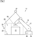
- Fig. 1 and 2 simplified illustrated loading / unloading 11 belongs to a production line and includes a robot 13, which in a basically known manner, a base 15, an articulated arm 17 and an end effector 19 has.
- a robot 13 instead of the robot 13, another type of automatic handling device, such as a gantry system, could be provided.
- a load carrier 21 in the form of a box-like container is placed on the floor 23.
- the objects 25 can be any individual parts or assemblies for automatic production.
- the end effector 19 of the robot 13 is designed to grip the objects 25 and can thus load a charge carrier 21 with objects 25 or unload objects 25 from a charge carrier 21.
- the working area of the robot 13 is monitored by a safety sensor 27 arranged above the robot 13. If necessary, the loading / unloading station 11 can also be provided with a plurality of safety sensors 27.
- the safety sensor 27 is preferably embodied as a 3D camera emitting depth information and spans a protective field 29 configured on the software side.
- An unillustrated control device of the loading / unloading station 11 communicates with the safety sensor 27 and ensures that, in the event of any intrusion of objects into the protective field 29, the robot 13 and optionally further movable system components are transferred to a safe state.
- Fig. 2 It can be seen that on both sides of the protective field 29 mechanical barriers 30 such. B. Fences are.
- an empty load carrier 21 is transported to the loading / unloading station 11 and placed on the floor 23. Subsequently, by means of the robot 13, objects 25 are removed one after the other from an object supply, not shown, and stored in the charge carrier 21. As soon as the charge carrier 21 is completely filled with or filled with objects, it is transported away again.
- the procedure is analogous, wherein initially a filled or populated load carrier 21 is transported to the loading / unloading station 11 and parked in the working area of the robot 13. The objects 25 are then removed one by one from the load carrier 21 by means of the robot 13 and fed to further processing in the production line.
- the transport of the charge carriers 21 to the loading / unloading station 11 and the removal of the load carriers 21 from the loading / unloading station 11 are preferably carried out by means of a forklift truck, a lift truck or a driverless transport system.
- the loading / unloading station 11 comprises a sensor arrangement 33, by means of which the position and the orientation of the charge carrier 21 within the working range of the robot 13 can be determined.
- the sensor assembly 33 in the illustrated embodiment comprises three distance sensors or 3D sensors 33a-c, the measuring fields are directed to respective side surfaces of the charge carrier 21. From a professional point of view, it goes without saying that a multiplicity of further sensor configurations is possible in order to detect the position of the charge carrier 21.
- the sensor arrangement 33 is connected to a control device 35 of the robot 13 and is configured to transmit the determined position of the parked load carrier 21 to the control device 35. If the charge carrier 21 is not parked exactly at the predetermined position, the corresponding incorrect positioning during operation of the robot 13 is taken into account. The robot 13 thus does not attack even with a mispositioned charge carrier 21. Collisions between the robot 13 and the charge carrier 21 are excluded.
- the sensor arrangement 33 could also be connected to the control device of a further robot, not shown, which is designed to handle charge carriers 21 and, if necessary, to correct the position of the parked charge carrier 21. In such an embodiment of the invention, not shown, the transmission of the determined position to the control device 35 of the robot 25 intended for handling the objects 25 would not necessarily be necessary. In principle, the sensor arrangement 33 could also be connected to a higher-level control device of the loading / unloading station 11.
- the safety sensor 27 could be designed to determine the position and orientation of the charge carrier 21 within the working range of the robot 13 and to transmit the determined position of the parked load carrier 21 to the control device 35. In such an embodiment, the safety sensor 27 would take over the task of the sensor arrangement and thus represent the sensor arrangement.
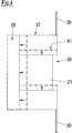
- Fig. 4 shows that the protective field 29 has an outer edge 37 (shown in phantom) and one along a recess 39 extending inner edge 41 (shown in phantom).
- the recess 39 serves to receive the charge carrier 21.
- the inner edge 41 is, as in Fig. 4 represented by arrows, adjusted on the basis of the determined position of the charge carrier 21, on the one hand to avoid a machine shutdown when entering the charge carrier 21 in the protective field 29 and on the other hand exclude a safety-critical gap between the carrier 21 and the inner edge 41 of the protective field 29.
- the outer edge 37 is adapted to maintain the standardized safety distances to the carrier 21.
- the protective field 29 can also be moved to adapt to the determined position of the charge carrier 21 as a whole.
- any incorrect positioning of the carrier 21 is automatically taken into account both in the control of the robot 13 and in the determination of the protective field 29, an accurate and prudent stopping of the carrier 21 during transport and careful removal of the carrier 21 during removal is not required. It is sufficient, in particular, that the charge carrier 21 is only parked approximately at the correct position. Accordingly, it is preferred that no mechanical stop for fixing the position of the charge carriers 21 is provided in the working area of the robot 13. In addition, it is not necessary to mark the predetermined position as such. Instead, a section of the work area can be defined as a tolerance range and marked accordingly, in which a parking of carriers 21 is permitted. For the operator of a forklift or lift truck, it is easy to place the load carriers 21 within the tolerance range and not to pay attention to a correct positioning. Likewise, it is advantageous that when transporting the charge carrier 21, it is not necessary to pay attention to a mechanical stop or the like. The invention thus enables a particularly efficient operation of the loading / unloading station 11 within the production line.
Landscapes
- Engineering & Computer Science (AREA)
- Robotics (AREA)
- Mechanical Engineering (AREA)
- Forklifts And Lifting Vehicles (AREA)
Abstract
Bei einem Verfahren zum Beladen von Ladungsträgern mit Objekten und/oder zum Entnehmen von Objekten von Ladungsträgern werden die Ladungsträger jeweils zu einer Be-/Entladestation transportiert und im Arbeitsbereich einer automatischen Objekt- Handhabungseinrichtung abgestellt. Mittels der automatischen Objekt-Handhabungseinrichtung wird jeweils wenigstens ein Objekt in oder auf einen abgestellten Ladungsträger gelegt oder von einem abgestellten Ladungsträger entnommen. Die Position des abgestellten Ladungsträgers innerhalb des Arbeitsbereichs wird erfindungsgemäß durch eine Sensoranordnung ermittelt und die ermittelte Position wird an eine der Be-/Entladestation zugeordnete Steuereinrichtung übermittelt. Die Erfindung betrifft außerdem eine Be-/Entladestation, mit der ein erfindungsgemäßes Verfahren durchgeführt werden kann.In a method for loading charge carriers with objects and / or for removing objects from load carriers, the load carriers are each transported to a loading / unloading station and parked in the working area of an automatic object handling device. By means of the automatic object handling device, at least one object is placed in or on a parked charge carrier or removed from a parked charge carrier. The position of the parked load carrier within the work area is inventively determined by a sensor arrangement and the determined position is transmitted to one of the loading / unloading station associated control device. The invention also relates to a loading / unloading station with which a method according to the invention can be carried out.
Description
Die vorliegende Erfindung betrifft ein Verfahren zum Beladen von Ladungsträgern, wie Kisten oder Paletten, mit Objekten und/oder zum Entnehmen von Objekten von solchen Ladungsträgern, wobei die Ladungsträger jeweils zu einer Be-/Entladestation transportiert und im Arbeitsbereich einer automatischen Objekt-Handhabungseinrichtung der Be-/Entladestation abgestellt werden, und wobei mittels der automatischen Objekt-Handhabungseinrichtung jeweils wenigstens ein Objekt in oder auf einen abgestellten Ladungsträger gelegt oder von einem abgestellten Ladungsträger entnommen wird. Die Erfindung betrifft außerdem eine Be-/Entladestation, mit der ein solches Verfahren durchgeführt werden kann.The present invention relates to a method for loading load carriers, such as boxes or pallets, with objects and / or for removing objects from such load carriers, wherein the load carriers each transported to a loading / unloading station and in the working area of an automatic object handling device of Be - / Unloading station are turned off, and wherein by means of the automatic object handling device in each case at least one object placed in or on a parked charge carrier or removed from a parked charge carrier. The invention also relates to a loading / unloading station with which such a method can be carried out.
Das automatische Beladen und Entladen von Ladungsträgern ist in verschiedenen Bereichen der Technik von Bedeutung. Beispielsweise müssen in einer automatisierten Produktion häufig Bauteile oder Baugruppen gesammelt transportiert, aber einzeln verarbeitet werden. Zu diesem Zweck werden üblicherweise Ladungsträger mit mehreren gleichartigen Objekten zu einer Be-/Entladestation transportiert und dort mittels eines Handhabungssystems wie eines Roboters einzeln herausgegriffen, um sie der weiteren Verarbeitung zuzuführen. Der Roboter kann kontinuierlich weiterarbeiten, bis der Ladungsträger leer ist. Anschließend ist ein weiterer, mit Objekten befüllter Ladungsträger bereitzustellen. In analoger Weise können im Bereich einer Be-/Entladestation Ladungsträger mit Objekten beladen werden. Bei den Ladungsträgern kann es sich um Kisten, Kästen, Wannen, Paletten oder dergleichen in beliebiger Größe handeln. Das Transportieren solcher Ladungsträger von bzw. zu der Be-/Entladestation erfolgt vorzugsweise mittels Staplern, Hubwagen oder führerlosen Transportsystemen (FTS).The automatic loading and unloading of load carriers is important in various fields of technology. For example, in automated production, components or assemblies often need to be collected, but processed individually. For this purpose, usually carriers are transported with several similar objects to a loading / unloading station and picked out there individually by means of a handling system such as a robot to supply them for further processing. The robot can continue to work continuously until the load carrier is empty. Subsequently, another, filled with objects charge carriers is to provide. In an analogous manner, charge carriers can be loaded with objects in the region of a loading / unloading station. The load carriers can be boxes, crates, tubs, pallets or the like of any size. The transporting of such load carriers from and / or to the loading / unloading station preferably takes place by means of stackers, lift trucks or driverless transport systems (AGVs).
Die herantransportierten Ladungsträger müssen im Arbeitsbereich der Objekt-Handhabungseinrichtung relativ genau positioniert werden, damit ein einwandfreier Betrieb der Objekt-Handhabungseinrichtung gewährleistet ist. Bei einer ungenauen Positionierung kann es insbesondere zu Kollisionen zwischen der Handhabungseinrichtung und dem Ladungsträger und somit zu Beschädigungen entsprechender Systemkomponenten kommen. Das genaue Positionieren der Ladungsträger ist für den Führer des betreffenden Transportmittels aufwändig und mühsam. Zur Erleichterung der manuellen Positionierung können mechanische Anschläge im Arbeitsbereich vorgesehen sein. Diese müssen jedoch vergleichsweise stabil ausgeführt werden und verteuern somit die Anlage. Außerdem zieht eine Dejustierung solcher Anschläge eine aufwändige Reparatur mit unerwünschtem Anlagenstillstand nach sich. Ein weiterer Nachteil von mechanischen Anschlägen besteht darin, dass bei einer Änderung der Position aufgrund einer Produktionsumstellung ein beträchtlicher Umbauaufwand anfällt.The transported carriers must be positioned relatively accurately in the working area of the object handling device, so that a proper operation of the object handling device is ensured. In the case of inaccurate positioning, collisions between the handling device and the charge carrier and thus damage to corresponding system components may occur in particular. Accurate positioning of the load carriers is cumbersome and troublesome for the driver of the respective means of transport. To facilitate manual positioning, mechanical stops may be provided in the work area. However, these must be carried out relatively stable and thus increase the cost of the system. In addition, a misalignment of such attacks entails a complex repair with unwanted plant downtime. Another disadvantage of mechanical stops is that a change in position due to a production change, a considerable conversion effort is incurred.
Es ist eine Aufgabe der Erfindung, das Be- und Entladen von Ladungsträgern an Be-/Entladestationen zu vereinfachen.It is an object of the invention to simplify the loading and unloading of load carriers at loading / unloading stations.
Die Lösung der Aufgabe erfolgt durch ein Verfahren mit den Merkmalen des Anspruchs 1 bzw. eine Be-/Entladestation mit den Merkmalen des Anspruches 10.The object is achieved by a method having the features of claim 1 or a loading / unloading station having the features of claim 10.
Erfindungsgemäß wird die Position des abgestellten Ladungsträgers innerhalb des Arbeitsbereichs durch eine Sensoranordnung ermittelt. Die so ermittelte Position wird an eine der Be-/Entladestation zugeordnete Steuereinrichtung übermittelt. Die Steuereinrichtung kann die gegebenenfalls vorhandene Abweichung zwischen der vorgegebenen Position und der tatsächlichen Position des abgestellten Ladungsträgers im weiteren Anlagenbetrieb berücksichtigen, so dass unerwünschte Kollisionen vermieden werden. Für die antransportierten Ladungsträger bedeutet dies, dass sie lediglich ungefähr an der gewünschten Position abgestellt werden müssen. Für das betreffende Personal ist dies mit einer wesentlichen Vereinfachung der Arbeitsabläufe verbunden, da das mühsame Einpassen der Ladungsträger entfällt. Auch das Entfernen der Ladungsträger aus dem Arbeitsbereich wird vereinfacht, da es nicht vorsichtig und langsam erfolgen muss. Die Erfindung ermöglicht so einen insgesamt strafferen Betriebsablauf und somit eine Beschleunigung des zugehörigen Produktionsprozesses.According to the invention, the position of the parked load carrier within the work area is determined by a sensor arrangement. The position determined in this way is transmitted to a control device associated with the loading / unloading station. The control device can take into account the possibly existing deviation between the predetermined position and the actual position of the parked load carrier in the further plant operation, so that undesired collisions are avoided. For the transported charge carriers, this means that they only have to be parked approximately at the desired position. For the staff in question this is associated with a substantial simplification of the work processes, since the tedious fitting of the load carrier is eliminated. Also, the removal of the charge carriers from the work area is simplified because it does not have to be careful and slow. The invention thus enables an overall tighter operation and thus an acceleration of the associated production process.
Im Zusammenhang mit den abzustellenden oder abgestellten Ladungsträgern ist der Begriff "Position" breit zu verstehen und soll insbesondere die Schwerpunktslage ebenso wie gegebenenfalls die Ausrichtung, also zum Beispiel die Drehlage und/oder die Verkippung, einschließen.The term "position" is to be understood broadly in connection with the load carriers to be dropped off or parked and should in particular include the center of gravity as well as, if appropriate, the orientation, for example the rotational position and / or the tilting.
Bei der Sensoranordnung kann es sich um einen einzelnen Sensor oder um eine Gruppe von mehreren Sensoren handeln. Es ist nicht zwingend erforderlich, dass die Sensoranordnung eigens für den Zweck der Ermittlung der Position der Ladungsträger vorgesehen ist. Insbesondere könnte ein zum Überwachen des Arbeitsbereichs vorgesehener Sicherheitssensor dazu verwendet werden, die Position des abgestellten Ladungsträgers innerhalb des Arbeitsbereichs zu ermitteln und die ermittelte Position an eine der Be-/Entladestation zugeordnete Steuereinrichtung zu übermitteln. Bevorzugt ist einem solchen Sicherheitssensor ein Bildverarbeitungssystem zugeordnet, um einen abgestellten Ladungsträger zum Beispiel an seiner Form zu erkennen. In einem solchen Fall wäre der Sicherheitssensor Teil der Sensoranordnung oder würde deren Aufgabe vollständig übernehmen.The sensor arrangement may be a single sensor or a group of multiple sensors. It is not absolutely necessary that the sensor arrangement is provided specifically for the purpose of determining the position of the charge carriers. In particular, a safety sensor provided for monitoring the working area could be used to determine the position of the parked load carrier within the working area and to transmit the determined position to a control device associated with the loading / unloading station. Such a security sensor is preferably associated with an image processing system in order to recognize a parked charge carrier, for example, by its shape. In such a case, the safety sensor would be part of the sensor assembly or would completely take over its task.
Sehr einfach und robust ist jedoch eine Ausgestaltung, bei der für die Sensoranordnung ein oder mehrere zum Beispiel als Abstandssensoren ausgestaltete Sensoren verwendet werden, die an entsprechenden Stellen um den Arbeitsbereich angeordnet sind, um die Position eines Ladungsträgers zu bestimmen. Vorzugsweise ist ein Abschnitt des Arbeitsbereichs als Toleranzbereich festgelegt, in welchem ein Abstellen von Ladungsträgern zulässig ist, wobei mittels der Sensoranordnung zumindest der Toleranzbereich und vorzugsweise ausschließlich der Toleranzbereich überwacht wird. Im Allgemeinen bereitet es dem für den Transport der Ladungsträger zuständigen Personal keine Probleme, beim Abstellen der Ladungsträger die festgelegte Position annähernd einzuhalten. Durch Beschränkung der Sensorüberwachung auf einen relativ kleinen Toleranzbereich um die gewünschte Position herum kann somit der Herstellungs- und Betriebsaufwand gering gehalten werden, Durch eine Markierung des Toleranzbereichs kann das Positionieren weiter erleichtert werden.Very simple and robust, however, is an embodiment in which one or more, for example, configured as a distance sensors sensors are used for the sensor arrangement, which are arranged at corresponding locations around the work area to determine the position of a charge carrier. Preferably, a portion of the working area is defined as a tolerance range in which a parking of charge carriers is permitted, wherein at least the tolerance range and preferably only the tolerance range is monitored by means of the sensor arrangement. In general, the personnel responsible for transporting the load carriers have no problems adhering approximately to the fixed position when parking the load carriers. By limiting the sensor monitoring to a relatively small tolerance range around the desired position, the manufacturing and operating costs can thus be kept low. By marking the tolerance range, the positioning can be further facilitated.
Eine Ausgestaltung der Erfindung sieht vor, dass die automatische Objekt-Handhabungseinrichtung programmgesteuert ist und eine Steuereinrichtung aufweist, wobei die ermittelte Position an die Steuereinrichtung der programmgesteuerten Objekt-Handhabungseinrichtung übermittelt wird und das Programm der programmgesteuerten Objekt-Handhabungseinrichtung bedarfsweise an die übermittelte Position des Ladungsträgers angepasst wird. Auf diese Weise ist sichergestellt, dass die Handhabungseinrichtung stets die korrekten Bewegungen ausführt und die gewünschten Objekte ergreift - unabhängig davon, an welcher Position der Ladungsträger mit den Objekten tatsächlich abgestellt ist.An embodiment of the invention provides that the automatic object handling device is program-controlled and has a control device, wherein the determined position is transmitted to the control device of the program-controlled object handling device and the program of the program-controlled object handling device adapted as needed to the transmitted position of the charge carrier becomes. In this way, it is ensured that the handling device always performs the correct movements and takes the desired objects - regardless of where the carrier is actually parked with the objects.
Eine weitere Ausgestaltung der Erfindung sieht vor, dass die Be-/Entladestation eine automatische Ladungsträger-Handhabungseinrichtung mit einer Steuereinrichtung aufweist, wobei die ermittelte Position an die Steuereinrichtung der Ladungsträger-Handhabungseinrichtung übermittelt wird und mittels der Ladungsträger-Handhabungseinrichtung anhand der übermittelten Position eine bedarfsweise Positionskorrektur des betreffenden abgestellten Ladungsträgers vorgenommen wird. Sollte also die tatsächliche Position des abgestellten Ladungsträgers von der vorgegebenen Position abweichen, so sorgt die Ladungsträger-Handhabungseinrichtung, bei der es sich insbesondere um einen weiteren Roboter handeln kann, für ein Verstellen, Verschieben oder Verdrehen des Ladungsträgers in die korrekte Position. Die Steuerung der Objekt-Handhabungseinrichtung kann davon im Prinzip unbeeinflusst bleiben.A further embodiment of the invention provides that the loading / unloading station has an automatic carrier handling device with a control device, wherein the determined position is transmitted to the control device of the carrier handling device and by means of the carrier handling device based on the transmitted position, a position correction as required the relevant parked carrier. If, therefore, the actual position of the parked load carrier deviates from the predetermined position, then the load carrier handling device, which may in particular be a further robot, ensures for adjusting, moving or twisting the load carrier into the correct position. The control of the object handling device can remain unaffected in principle.
Gemäß einer weiteren Ausführungsform der Erfindung wird zumindest ein Teil des Arbeitsbereichs durch wenigstens einen Sicherheitssensor unter Ausbildung wenigstens eines Schutzfeldes überwacht, wobei das Schutzfeld bedarfsweise an die ermittelte Position des Ladungsträgers angepasst wird. An Be-/Entladestationen ist es im Allgemeinen erforderlich, das im Bereich der Maschinen arbeitende Personal mittels Sicherheitssensoren vor Unfällen zu schützen. Als Sicherheitssensoren können Kameras, Abstandssensoren oder Scanner, insbesondere 3D-Kameras oder Lichtlaufzeit-Kameras, zum Einsatz kommen. Derartige Sicherheitssensoren spannen üblicherweise ein oder mehrere Schutzfelder auf und sorgen dafür, dass beim Eindringen eines Objekts in ein Schutzfeld die zugehörige Maschine in einen sicheren Zustand, beispielsweise in den Stillstand, überführt wird. Das Schutzfeld ist hierbei nicht zwingend identisch mit dem Messfeld oder Gesichtsfeld des betreffenden Sensors. Vielmehr ist das Schutzfeld unabhängig vom Messfeld softwareseitig konfiguriert. Durch Anpassung des Schutzfelds an die ermittelte Position des Ladungsträgers ist sichergestellt, dass der Personenschutz durch einen fehlpositionierten Ladungsträger in keiner Weise beeinträchtigt ist. Außerdem wird ein unerwünschter Anlagenstillstand vermieden.According to a further embodiment of the invention, at least a part of the working area is monitored by at least one safety sensor to form at least one protective field, wherein the protective field is adapted as needed to the determined position of the charge carrier. At loading / unloading stations it is generally necessary to protect personnel working in the machine area from accidents by means of safety sensors. As security sensors cameras, distance sensors or scanners, in particular 3D cameras or light-time cameras, can be used. Such safety sensors usually span one or more protective fields and ensure that when an object enters a protective field, the associated machine is transferred to a safe state, for example to a standstill. The protective field is not necessarily identical to the measuring field or field of view of the relevant sensor. Rather, the protective field is configured independently of the measuring field on the software side. By adapting the protective field to the determined position of the charge carrier, it is ensured that the personal protection is in no way impaired by a mispositioned charge carrier. In addition, an undesirable system downtime is avoided.
Zur Berücksichtigung eines Sicherheitsabstandes kann zumindest ein äußerer Rand des wenigstens einen Schutzfeldes an die ermittelte Position des Ladungsträgers angepasst werden. Sollte also beispielsweise ein Ladungsträger etwas zu weit links abgestellt sein, so wird das Schutzfeld zur linken Seite hin entsprechend vergrößert, um so die Einhaltung des Sicherheitsabstands zu gewährleisten.To take into account a safety distance, at least one outer edge of the at least one protective field can be adapted to the determined position of the charge carrier. If, for example, a load carrier is parked too far to the left, the protective field is increased to the left in order to ensure compliance with the safety distance.
Eine besonders einfache Schutzfeldanpassung wird dadurch erzielt, dass das wenigstens eine Schutzfeld zur Anpassung an die ermittelte Position des Ladungsträgers als Ganzes verschoben wird.A particularly simple protective field adaptation is achieved in that the at least one protective field is displaced to adapt to the determined position of the charge carrier as a whole.
Gemäß einer weiteren Ausgestaltung der Erfindung weist das wenigstens eine Schutzfeld einen äußeren Rand sowie einen entlang einer Aussparung des Schutzfeldes verlaufenden inneren Rand auf, wobei ausschließlich der innere Rand an die ermittelte Position des Ladungsträgers angepasst wird. Eine Aussparung des Schutzfeldes kann im Allgemeinen zur Aufnahme des Ladungsträgers erforderlich sein. Denn innerhalb des für den Ladungsträger reservierten Raumes darf in der Regel kein aktives Schutzfeld definiert sein. Durch eine Anpassung des entlang der Aussparung verlaufenden inneren Schutzfeldrandes wird im Falle einer Fehlpositionierung des Ladungsträgers eine unerwünschte Sicherheitsabschaltung vermieden. Es könnte grundsätzlich auch eine Erkennung des Ladungsträgers innerhalb eines Schutzfeldes vorgesehen sein, beispielsweise mittels eines mit dem Sicherheitssensor zusammenarbeitenden Bildverarbeitungssystems, um auf diese Weise eine Sicherheitsabschaltung durch einen vorhandenen Ladungsträger zu vermeiden. Eine Aussparung des Schutzfeldes ist dann nicht zwingend notwendig.According to a further embodiment of the invention, the at least one protective field has an outer edge and an inner edge extending along a recess of the protective field, wherein only the inner edge is adapted to the determined position of the charge carrier. A recess of the protective field may generally be required to accommodate the charge carrier. Because within the space reserved for the load carrier usually no active protective field may be defined. By adapting the inner protective field edge extending along the recess, an undesired safety shutdown is avoided in the case of a faulty positioning of the charge carrier. In principle, detection of the charge carrier within a protective field could also be provided, for example by means of an image processing system cooperating with the security sensor, in order to avoid a safety shutdown by an existing charge carrier in this way. A recess of the protective field is then not absolutely necessary.
Mittels der Sensoranordnung kann ferner ein aktueller Beladezustand des Ladungsträgers, insbesondere ein aktueller Füllstand, ermittelt und an die oder eine weitere Steuereinrichtung übermittelt werden. Der Beladezustand ist ein Maß für den noch verfügbaren Objektvorrat. Der Sensoranordnung kommt bei dieser Ausgestaltung eine Doppelfunktion zu, indem sie sowohl durch Berücksichtigung von Fehlpositionierungen den Arbeitsablauf vereinfacht als auch durch Auswerten von Beladungsinformationen die Anlageneffizienz steigert.By means of the sensor arrangement, furthermore, a current loading state of the charge carrier, in particular a current fill level, can be determined and transmitted to the or a further control device. The loading status is a measure of the available object supply. In this embodiment, the sensor arrangement has a dual function in that it simplifies the workflow both by taking account of incorrect positioning and also increases the system efficiency by evaluating loading information.
Die Erfindung betrifft auch eine Be-/Entladestation zum Beladen von Ladungsträgern wie Kisten oder Paletten mit Objekten und/oder zum Entnehmen von Objekten von solchen Ladungsträgern, mit einer automatischen Objekt- Handhabungseinrichtung, welche einen Arbeitsbereich aufweist und zum Legen jeweils wenigstens eines Objekts in oder auf einen im Arbeitsbereich abgestellten Ladungsträger und/oder zum Entnehmen eines Objekts von einem im Arbeitsbereich abgestellten Ladungsträger ausgebildet ist, wobei die Be-/Entladestation insbesondere zum Durchführen eines wie vorstehend beschriebenen Verfahrens ausgebildet ist.The invention also relates to a loading / unloading station for loading load carriers such as boxes or pallets with objects and / or for removing objects of such load carriers, with an automatic object handling device which has a work area and is designed to place at least one object in or on a load carrier parked in the work area and / or to remove an object from a load carrier parked in the work area; / Entladestation is designed in particular for performing a method as described above.
Eine erfindungsgemäße Be-/Entladestation weist eine Sensoranordnung zum Ermitteln der Position eines abgestellten Ladungsträgers innerhalb des Arbeitsbereichs sowie Übertragungsmittel zum Übermitteln der ermittelten Position an eine der Be-/Entladestation zugeordnete Steuereinrichtung auf. Die Übertragungsmittel können je nach Anwendung eine kabelgebundene oder eine drahtlose Verbindung zwischen der Sensoranordnung und der Steuereinrichtung bereitstellen.A loading / unloading station according to the invention has a sensor arrangement for determining the position of a parked load carrier within the working area and transmission means for transmitting the determined position to a control device associated with the loading / unloading station. The transmission means may provide a wired or wireless connection between the sensor assembly and the controller, depending on the application.
Die Sensoranordnung kann wenigstens eine Kamera umfassen und/oder mehrere Messfelder aufweisen. Bei der Kamera kann es sich insbesondere um eine 3D-Stereokamera oder eine Lichtlaufzeitkamera, welche als Tiefenkamera ausgestaltet ist und in der Lage ist, auch Tiefeninformationen auszugeben, handeln.The sensor arrangement may comprise at least one camera and / or have a plurality of measuring fields. The camera may be, in particular, a 3D stereo camera or a time of flight camera, which is designed as a depth camera and is capable of outputting depth information as well.
Bei der Sensoranordnung kann es sich um einen einzelnen Sensor oder um eine Gruppe von mehreren Sensoren handeln. Es ist nicht zwingend erforderlich, dass die Sensoranordnung eigens für den Zweck der Ermittlung der Position der Ladungsträger vorgesehen ist. Insbesondere könnte ein zum Überwachen des Arbeitsbereichs vorgesehener Sicherheitssensor dazu verwendet werden, die Position des abgestellten Ladungsträgers innerhalb des Arbeitsbereichs zu ermitteln und die ermittelte Position an eine der Be-/Entladestation zugeordnete Steuereinrichtung zu übermitteln. Bevorzugt ist einem solchen Sicherheitssensor ein Bildverarbeitungssystem zugeordnet, um einen abgestellten Ladungsträger zum Beispiel an seiner Form zu erkennen. In einem solchen Fall wäre der Sicherheitssensor Teil der Sensoranordnung oder würde deren Aufgabe vollständig übernehmen.The sensor arrangement may be a single sensor or a group of multiple sensors. It is not absolutely necessary that the sensor arrangement is provided specifically for the purpose of determining the position of the charge carriers. In particular, a safety sensor provided for monitoring the working area could be used to determine the position of the parked load carrier within the working area and to transmit the determined position to a control device associated with the loading / unloading station. Such a security sensor is preferably associated with an image processing system in order to recognize a parked charge carrier, for example, by its shape. In such a case, the safety sensor would be Part of the sensor array or would completely take over their task.
Sehr einfach und robust ist jedoch eine Ausgestaltung, bei der für die Sensoranordnung ein oder mehrere zum Beispiel als Abstandssensoren ausgestaltete Sensoren verwendet werden, die an entsprechenden Stellen um den Arbeitsbereich angeordnet sind, um die Position eines Ladungsträgers zu bestimmen.Very simple and robust, however, is an embodiment in which one or more, for example, configured as a distance sensors sensors are used for the sensor arrangement, which are arranged at corresponding locations around the work area to determine the position of a charge carrier.
Gemäß einer Ausführungsform der Erfindung ist im Arbeitsbereich der automatischen Objekt-Handhabungseinrichtung kein mechanischer Anschlag zur Festlegung der Abstellposition der Ladungsträger vorgesehen. Aufgrund der automatischen Berücksichtigung von etwaigen Fehlpositionierungen ist ein solcher mechanischer Anschlag nicht notwendig. Für die Gesamtanlage ist das Fehlen eines Anschlags von Vorteil, da Produktionsumstellungen leichter realisiert werden können. Außerdem ist die Unfallgefahr reduziert.According to one embodiment of the invention, no mechanical stop for determining the parking position of the charge carriers is provided in the working area of the automatic object handling device. Due to the automatic consideration of any incorrect positioning such a mechanical stop is not necessary. For the entire system, the absence of an attack is advantageous because production changes can be made easier. In addition, the risk of accidents is reduced.
Gemäß einer speziellen Ausgestaltung einer erfindungsgemäßen Be-/Entladestation ist die automatische Objekt-Handhabungseinrichtung programmgesteuert und die Steuereinrichtung ist dazu ausgebildet, das Programm der programmgesteuerten Objekt-Handhabungseinrichtung bedarfsweise an die ermittelte Position des Ladungsträgers anzupassen.According to a special embodiment of a loading / unloading station according to the invention, the automatic object handling device is program-controlled and the control device is designed to adapt the program of the program-controlled object handling device to the determined position of the charge carrier as required.
Gemäß einer weiteren Ausgestaltung ist eine Ladungsträger-Handhabungseinrichtung vorgesehen, welche dazu ausgebildet ist, anhand der ermittelten Position eine bedarfsweise Positionskorrektur des Ladungsträgers vorzunehmen.According to a further embodiment, a charge carrier handling device is provided, which is designed to carry out a position correction of the charge carrier as required using the determined position.
Bevorzugt umfasst eine erfindungsgemäße Be-/Entladestation wenigstens einen Sicherheitssensor zum Überwachen zumindest eines Teils des Arbeitsbereichs unter Ausbildung wenigstens eines Schutzfeldes, wobei eine dem wenigstens einen Sicherheitssensor zugeordnete Sicherheits-Steuereinrichtung dazu ausgebildet ist, das Schutzfeld bedarfsweise an die ermittelte Position des Ladungsträgers anzupassen.Preferably, a loading / unloading station according to the invention comprises at least one safety sensor for monitoring at least part of the working area to form at least one protective field, wherein a safety control device assigned to the at least one safety sensor is designed for this purpose is to adapt the protective field as needed to the determined position of the charge carrier.
Insbesondere kann ein Abschnitt des Arbeitsbereichs als Toleranzbereich festgelegt sein, in welchem ein Abstellen von Ladungsträgern zulässig ist, wobei die Sensoranordnung vorzugsweise dazu ausgebildet ist, ausschließlich den Toleranzbereich zu überwachen.In particular, a section of the working area can be defined as a tolerance range in which a parking of charge carriers is permitted, wherein the sensor arrangement is preferably designed to monitor only the tolerance range.
Die Steuereinrichtung kann einen Schreib-/Lese-Speicher umfassen, in welchem Prozessparameter, wie die Dimensionierung der Ladungsträger, abgelegt sind. Bei einem Produktionswechsel können die abgespeicherten Prozessparameter einfach und schnell geändert werden.The control device may comprise a read / write memory in which process parameters, such as the dimensioning of the charge carriers, are stored. During a production change, the stored process parameters can be changed easily and quickly.
Weiterbildungen der Erfindung sind auch in den abhängigen Ansprüchen, der Beschreibung sowie den beigefügten Zeichnungen angegeben.Further developments of the invention are set forth in the dependent claims, the description and the accompanying drawings.
Die Erfindung wird nachfolgend beispielhaft unter Bezugnahme auf die Zeichnungen beschrieben.
- Fig. 1
- ist eine vereinfachte Seitenansicht einer erfindungsgemäßen Be-/Entladestation.
- Fig. 2
- ist eine Draufsicht auf die Be-/Entladestation gemäß
Fig. 1 . - Fig. 3
- ist eine Teildarstellung der in
Fig. 2 gezeigten Anordnung, welche die Funktion einer Sensoranordnung der Be-/Entladestation verdeutlicht. - Fig. 4
- ist eine weitere Teildarstellung der in
Fig. 2 gezeigten Anordnung, welche die Anpassung eines inneren Randes eines Schutzfelds der Sensoranordnung verdeutlicht. - Fig. 5
- ist eine weitere Teildarstellung der in
Fig. 2 gezeigten Anordnung, welche die Anpassung eines äußeren Rands des Schutzfelds verdeutlicht.
- Fig. 1
- is a simplified side view of a loading / unloading station according to the invention.
- Fig. 2
- is a plan view of the loading / unloading station according to
Fig. 1 , - Fig. 3
- is a partial representation of in
Fig. 2 shown arrangement which illustrates the function of a sensor arrangement of the loading / unloading station. - Fig. 4
- is another partial representation of in
Fig. 2 arrangement shown which illustrates the adaptation of an inner edge of a protective field of the sensor assembly. - Fig. 5
- is another partial representation of in
Fig. 2 shown arrangement which illustrates the adaptation of an outer edge of the protective field.
Die in
Der Arbeitsbereich des Roboters 13 wird durch einen oberhalb des Roboters 13 angeordneten Sicherheitssensor 27 überwacht. Bei Bedarf kann die Be-/Entladestation 11 auch mit mehreren Sicherheitssensoren 27 versehen sein. Der Sicherheitssensor 27 ist vorzugsweise als Tiefeninformationen ausgebende 3D-Kamera ausgeführt und spannt ein softwareseitig konfiguriertes Schutzfeld 29 auf. Eine nicht dargestellte Steuereinrichtung der Be-/Entladestation 11 steht mit dem Sicherheitssensor 27 in Verbindung und sorgt dafür, dass bei jeglichem Eindringen von Objekten in das Schutzfeld 29 der Roboter 13 und gegebenenfalls weitere bewegliche Anlagenkomponenten in einen sicheren Zustand überführt wird. In
Zum Beladen eines Ladungsträgers 21 mit Objekten 25 wird zunächst ein leerer Ladungsträger 21 zu der Be-/Entladestation 11 transportiert und auf dem Boden 23 abgestellt. Anschließend werden mittels des Roboters 13 einzeln und nacheinander Objekte 25 aus einem nicht dargestellten Objektvorrat entnommen und in dem Ladungsträger 21 abgelegt. Sobald der Ladungsträger 21 vollständig mit Objekten befüllt oder bestückt ist, wird er wieder abtransportiert.For loading a
Zum Entladen von Objekten 25 aus dem Ladungsträger 21 wird in analoger Weise vorgegangen, wobei zunächst ein befüllter oder bestückter Ladungsträger 21 zu der Be-/Entladestation 11 transportiert und im Arbeitsbereich des Roboters 13 abgestellt wird. Die Objekte 25 werden dann mittels des Roboters 13 einzeln nacheinander aus dem Ladungsträger 21 entnommen und einer weiteren Verarbeitung in der Produktionslinie zugeführt.For unloading objects 25 from the
Der Antransport der Ladungsträger 21 zu der Be-/Entladestation 11 sowie der Abtransport der Ladungsträger 21 von der Be-/Entladestation 11 erfolgt vorzugsweise mittels eines Gabelstaplers, Hubwagens oder eines führerlosen Transportsystems.The transport of the
Die Be-/Entladestation 11 umfasst eine Sensoranordnung 33, mittels welcher die Lage und die Ausrichtung des Ladungsträgers 21 innerhalb des Arbeitsbereichs des Roboters 13 ermittelbar ist. Wie aus
Die Sensoranordnung 33 steht mit einer Steuereinrichtung 35 des Roboters 13 in Verbindung und ist dazu ausgebildet, die ermittelte Position des abgestellten Ladungsträgers 21 an die Steuereinrichtung 35 zu übermitteln. Sollte der Ladungsträger 21 nicht exakt an der vorgegebenen Position abgestellt sein, so wird die entsprechende Fehlpositionierung beim Betrieb des Roboters 13 berücksichtigt. Der Roboter 13 greift somit auch bei einem fehlpositionierten Ladungsträger 21 nicht daneben. Kollisionen zwischen dem Roboter 13 und dem Ladungsträger 21 sind ausgeschlossen. Die Sensoranordnung 33 könnte auch mit der Steuereinrichtung eines nicht dargestellten weiteren Roboters in Verbindung stehen, der zum Handhaben von Ladungsträgern 21 ausgebildet ist und bei Bedarf für eine Positionskorrektur des abgestellten Ladungsträgers 21 sorgt. Bei einer solchen, nicht dargestellten Ausführungsform der Erfindung wäre das Übermitteln der ermittelten Position an die Steuereinrichtung 35 des zum Handhaben der Objekte 25 vorgesehenen Roboters 13 nicht zwingend erforderlich. Grundsätzlich könnte die Sensoranordnung 33 auch mit einer übergeordneten Steuereinrichtung der Be-/Entladestation 11 in Verbindung stehen.The
Bei einer nicht dargestellten Ausführungsform könnte der Sicherheitssensor 27 dazu ausgebildet sein, die Lage und die Ausrichtung des Ladungsträgers 21 innerhalb des Arbeitsbereichs des Roboters 13 zu ermitteln und die ermittelte Position des abgestellten Ladungsträgers 21 an die Steuereinrichtung 35 zu übermitteln. Bei einer solchen Ausgestaltung würde der Sicherheitssensor 27 die Aufgabe der Sensoranordnung mit übernehmen und insofern die Sensoranordnung darstellen.In one embodiment, not shown, the
Eine etwaige Fehlpositionierung des Ladungsträgers 21 wird nicht nur bei der Bewegungssteuerung des Roboters 13 berücksichtigt, sondern führt auch zu einer Anpassung des Schutzfeldes 29. Aus
Wie in
Dadurch, dass eventuelle Fehlpositionierungen des Ladungsträgers 21 sowohl bei der Steuerung des Roboters 13 als auch bei der Festlegung des Schutzfeldes 29 automatisch berücksichtigt werden, ist ein exaktes und umsichtiges Abstellen des Ladungsträgers 21 beim Antransport sowie ein vorsichtiges Entfernen des Ladungsträgers 21 beim Abtransport nicht erforderlich. Es reicht insbesondere aus, dass der Ladungsträger 21 lediglich ungefähr an der korrekten Position abgestellt wird. Dementsprechend ist es bevorzugt, dass im Arbeitsbereich des Roboters 13 kein mechanischer Anschlag zur Festlegung der Position der Ladungsträger 21 vorgesehen ist. Außerdem ist es nicht erforderlich, die vorgegebene Position als solche zu markieren. Stattdessen kann ein Abschnitt des Arbeitsbereichs als Toleranzbereich festgelegt und entsprechend markiert sein, in welchem ein Abstellen von Ladungsträgern 21 zulässig ist. Für den Bediener eines Gabelstaplers oder Hubwagens ist es einfach, die Ladungsträger 21 innerhalb des Toleranzbereichs abzustellen und hierbei nicht weiter auf eine korrekte Positionierung zu achten. Ebenso ist es von Vorteil, dass beim Abtransport der Ladungsträger 21 nicht auf einen mechanischen Anschlag oder dergleichen geachtet werden muss. Die Erfindung ermöglicht somit einen besonders effizienten Betrieb der Be-/Entladestation 11 innerhalb der Produktionslinie.The fact that any incorrect positioning of the
- 1111
- Be-/EntladestationLoading / unloading station
- 1313
- Roboterrobot
- 1515
- BasisBase
- 1717
- GelenkarmanordnungArticulating arm assembly
- 1919
- Endeffektorend effector
- 2121
- Ladungsträgercharge carrier
- 2323
- Bodenground
- 2525
- Objektobject
- 2727
- Sicherheitssensorsecurity sensor
- 2929
- Schutzfeldprotection field
- 3030
- Absperrungbarrier
- 3333
- Sensoranordnungsensor arrangement
- 33a - c33a - c
- Abstandssensordistance sensor
- 3535
- Steuereinrichtungcontrol device
- 3737
- äußerer Randouter edge
- 3939
- Aussparungrecess
- 4141
- innerer Randinner edge
Claims (15)
dadurch gekennzeichnet, dass
die Position des abgestellten Ladungsträgers (21) innerhalb des Arbeitsbereichs durch eine Sensoranordnung (33) ermittelt wird und die ermittelte Position an eine der Be-/Entladestation (11) zugeordnete Steuereinrichtung (35) übermittelt wird.Method for loading load carriers (21), such as boxes or pallets, with objects (25) and / or for removing objects (25) from such load carriers (21), wherein the load carriers (21) each lead to a loading / unloading station ( 11) and in the working area of an automatic object handling device (13) of the loading / unloading station (11) are turned off, and wherein by means of the automatic object handling device (13) in each case at least one object (25) in or on a parked charge carrier ( 21) or removed from a parked load carrier (21),
characterized in that
the position of the parked load carrier (21) within the work area is determined by a sensor arrangement (33) and the determined position is transmitted to a control device (35) assigned to the loading / unloading station (11).
dadurch gekennzeichnet, dass
ein Abschnitt des Arbeitsbereichs als Toleranzbereich festgelegt ist, in welchem ein Abstellen von Ladungsträgern (21) zulässig ist, wobei mittels der Sensoranordnung (33) zumindest der Toleranzbereich und vorzugsweise ausschließlich der Toleranzbereich überwacht wird.Method according to claim 1,
characterized in that
a section of the working area is defined as a tolerance range in which a parking of charge carriers (21) is permitted, wherein at least the tolerance range and preferably only the tolerance range is monitored by means of the sensor arrangement (33).
dadurch gekennzeichnet, dass die automatische Objekt-Handhabungseinrichtung (13) programmgesteuert ist und eine Steuereinrichtung (35) aufweist, wobei die ermittelte Position an die Steuereinrichtung (35) der programmgesteuerten Objekt-Handhabungseinrichtung (13) übermittelt wird und das Programm der programmgesteuerten Objekt-Handhabungseinrichtung (13) bedarfsweise an die übermittelte Position des Ladungsträgers (21) angepasst wird.Method according to claim 1 or 2,
characterized in that the automatic object handling device (13) is program-controlled and has a control device (35), wherein the determined position is transmitted to the control device (35) of the program-controlled object handling device (13) and the program of the program-controlled object handling device (13) is adapted as needed to the transmitted position of the carrier (21).
dadurch gekennzeichnet, dass die Be-/Entladestation (11) eine automatische Ladungsträger-Handhabungseinrichtung mit einer Steuereinrichtung aufweist, wobei die ermittelte Position an die Steuereinrichtung der Ladungsträger-Handhabungseinrichtung übermittelt wird und mittels der Ladungsträger-Handhabungseinrichtung anhand der übermittelten Position eine bedarfsweise Positionskorrektur des betreffenden abgestellten Ladungsträgers (21) vorgenommen wird.Method according to one of the preceding claims,
characterized in that the loading / unloading station (11) comprises an automatic carrier handling device with a control device, wherein the determined position is transmitted to the control device of the carrier handling device and by means of the carrier handling device based on the transmitted position, a position correction of the relevant parked load carrier (21) is made.
dadurch gekennzeichnet, dass zumindest ein Teil des Arbeitsbereichs durch wenigstens einen Sicherheitssensor (27) unter Ausbildung wenigstens eines Schutzfeldes (29) überwacht wird, wobei das Schutzfeld (29) bedarfsweise an die ermittelte Position des Ladungsträgers (21) angepasst wird.Method according to one of the preceding claims,
characterized in that at least a portion of the working area is monitored by at least one safety sensor (27) forming at least one protective field (29), wherein the protective field (29) is adapted as needed to the determined position of the charge carrier (21).
dadurch gekennzeichnet, dass
zur Berücksichtigung eines Sicherheitsabstandes zumindest ein äußerer Rand (37) des wenigstens einen Schutzfeldes (29) an die ermittelte Position des Ladungsträgers (21) angepasst wird.Method according to claim 5,
characterized in that
at least one outer edge (37) of the at least one protective field (29) is adapted to the determined position of the charge carrier (21) to take account of a safety distance.
dadurch gekennzeichnet, dass
das wenigstens eine Schutzfeld (29) zur Anpassung an die ermittelte Position des Ladungsträgers (21) als Ganzes verschoben wird.Method according to claim 5 or 6,
characterized in that
the at least one protective field (29) is displaced to adapt to the determined position of the charge carrier (21) as a whole.
dadurch gekennzeichnet, dass
das wenigstens eine Schutzfeld einen äußeren Rand (37) sowie einen entlang einer Aussparung (39) des Schutzfeldes (29) verlaufenden inneren Rand (41) aufweist, wobei ausschließlich der innere Rand (41) an die ermittelte Position des Ladungsträgers (21) angepasst wird.Method according to claim 5,
characterized in that
the at least one protective field has an outer edge (37) and an inner edge (41) extending along a recess (39) of the protective field (29), wherein only the inner edge (41) is adapted to the determined position of the charge carrier (21) ,
dadurch gekennzeichnet, dass
mittels der Sensoranordnung (33) ferner ein aktueller Beladezustand des Ladungsträgers (21), insbesondere ein aktueller Füllstand, ermittelt und an die oder eine weitere Steuereinrichtung (35) übermittelt wird.Method according to one of the preceding claims,
characterized in that
Furthermore, a current loading state of the charge carrier (21), in particular a current filling level, is determined by means of the sensor arrangement (33) and transmitted to the or a further control device (35).
gekennzeichnet durch
eine Sensoranordnung (33) zum Ermitteln der Position eines abgestellten Ladungsträgers (21) innerhalb des Arbeitsbereichs sowie Übertragungsmittel zum Übermitteln der ermittelten Position an eine der Be-/Entladestation (11) zugeordnete Steuereinrichtung (35).Loading / unloading station (11) for loading load carriers (21), such as boxes or pallets, with objects (25) and / or for removing objects (25) from such load carriers (21), with an automatic object handling device (13 ), which has a work area and for laying in each case at least one object (25) in or on a parked in the work area load carrier (21) and / or for removing a Object (25) is formed by a parked in the work area charge carrier (21), wherein the loading / unloading station (11) is designed in particular for performing a method according to any one of the preceding claims,
marked by
a sensor arrangement (33) for determining the position of a parked load carrier (21) within the working area and transmission means for transmitting the determined position to a control device (35) associated with the loading / unloading station (11).
dadurch gekennzeichnet, dass die Sensoranordnung (33) wenigstens eine Kamera umfasst und/oder mehrere Messfelder aufweist.Loading / unloading station according to claim 10,
characterized in that the sensor arrangement (33) comprises at least one camera and / or has a plurality of measuring fields.
dadurch gekennzeichnet, dass im Arbeitsbereich der automatischen Objekt-Handhabungseinrichtung (13) kein mechanischer Anschlag zur Festlegung der Abstellposition der Ladungsträger (21) vorgesehen ist.Loading / unloading station according to claim 10 or 11,
characterized in that in the working area of the automatic object handling device (13) no mechanical stop for determining the parking position of the charge carriers (21) is provided.
dadurch gekennzeichnet, dass die automatische Objekt-Handhabungseinrichtung (13) programmgesteuert ist und die Steuereinrichtung (35) dazu ausgebildet ist, das Programm der programmgesteuerten Objekt-Handhabungseinrichtung (13) bedarfsweise an die ermittelte Position des Ladungsträgers (21) anzupassen.Loading / unloading station according to one of claims 10 to 12,
characterized in that the automatic object handling device (13) is program-controlled and the control device (35) is adapted to adapt the program of the program-controlled object handling device (13) as needed to the determined position of the charge carrier (21).
gekennzeichnet durch
eine Ladungsträger-Handhabungseinrichtung, welche dazu ausgebildet ist, anhand der ermittelten Position eine bedarfsweise Positionskorrektur des Ladungsträgers (21) vorzunehmen.Loading / unloading station according to one of claims 10 to 13,
marked by
a charge carrier handling device which is designed to carry out a position correction of the charge carrier (21) as required on the basis of the determined position.
gekennzeichnet durch
wenigstens einen Sicherheitssensor (27) zum Überwachen zumindest eines Teils des Arbeitsbereichs unter Ausbildung wenigstens eines Schutzfeldes (29), wobei eine dem wenigstens einen Sicherheitssensor (27) zugeordnete Sicherheits-Steuereinrichtung dazu ausgebildet ist, das Schutzfeld (29) bedarfsweise an die ermittelte Position des Ladungsträgers (21) anzupassen.Loading / unloading station according to one of claims 10 to 14,
marked by
at least one safety sensor (27) for monitoring at least a part of the working area to form at least one protective field (29), wherein a safety control device associated with the at least one safety sensor (27) is adapted to apply the protective field (29) to the determined position of the Load carrier (21) adapt.
Priority Applications (1)
| Application Number | Priority Date | Filing Date | Title |
|---|---|---|---|
| EP15171273.4A EP3103596A1 (en) | 2015-06-09 | 2015-06-09 | Method for loading load carriers and loading/unloading station |
Applications Claiming Priority (1)
| Application Number | Priority Date | Filing Date | Title |
|---|---|---|---|
| EP15171273.4A EP3103596A1 (en) | 2015-06-09 | 2015-06-09 | Method for loading load carriers and loading/unloading station |
Publications (1)
| Publication Number | Publication Date |
|---|---|
| EP3103596A1 true EP3103596A1 (en) | 2016-12-14 |
Family
ID=53541495
Family Applications (1)
| Application Number | Title | Priority Date | Filing Date |
|---|---|---|---|
| EP15171273.4A Ceased EP3103596A1 (en) | 2015-06-09 | 2015-06-09 | Method for loading load carriers and loading/unloading station |
Country Status (1)
| Country | Link |
|---|---|
| EP (1) | EP3103596A1 (en) |
Cited By (1)
| Publication number | Priority date | Publication date | Assignee | Title |
|---|---|---|---|---|
| US20220016779A1 (en) * | 2020-07-15 | 2022-01-20 | The Board Of Trustees Of The University Of Illinois | Autonomous Robot Packaging of Arbitrary Objects |
Citations (2)
| Publication number | Priority date | Publication date | Assignee | Title |
|---|---|---|---|---|
| DE102007026956A1 (en) * | 2007-06-12 | 2008-12-18 | Kuka Innotec Gmbh | Method and system for robot-guided depalletizing of tires |
| EP2745999A1 (en) * | 2011-08-19 | 2014-06-25 | Kabushiki Kaisha Yaskawa Denki | Robot system, robot control device, robot hand and method for controlling robot |
-
2015
- 2015-06-09 EP EP15171273.4A patent/EP3103596A1/en not_active Ceased
Patent Citations (2)
| Publication number | Priority date | Publication date | Assignee | Title |
|---|---|---|---|---|
| DE102007026956A1 (en) * | 2007-06-12 | 2008-12-18 | Kuka Innotec Gmbh | Method and system for robot-guided depalletizing of tires |
| EP2745999A1 (en) * | 2011-08-19 | 2014-06-25 | Kabushiki Kaisha Yaskawa Denki | Robot system, robot control device, robot hand and method for controlling robot |
Cited By (1)
| Publication number | Priority date | Publication date | Assignee | Title |
|---|---|---|---|---|
| US20220016779A1 (en) * | 2020-07-15 | 2022-01-20 | The Board Of Trustees Of The University Of Illinois | Autonomous Robot Packaging of Arbitrary Objects |
Similar Documents
| Publication | Publication Date | Title |
|---|---|---|
| DE102018124712B4 (en) | Work system, method of performing work on an object and robot | |
| EP3571020B1 (en) | Method and device for picking goods | |
| EP3289852B2 (en) | Transport automobile | |
| EP3601118B1 (en) | Production system with an agv for automatically discharging containers to picking shelves | |
| EP3638616B1 (en) | Container treatment machine with mobile robot for component exchange | |
| EP3020614B1 (en) | Conveyor system for conveying objects and control method for same | |
| EP2745982B1 (en) | Production system | |
| EP3875990B1 (en) | Bearing inspection system | |
| DE102007026956A1 (en) | Method and system for robot-guided depalletizing of tires | |
| DE102014005434A1 (en) | Control device for a robot for conveying a workpiece | |
| EP3446184B1 (en) | Safety device and safety method | |
| EP3953743B1 (en) | Manufacturing device and conveyor means | |
| DE102018106458A1 (en) | production system | |
| DE102011100281C5 (en) | Transport system for transporting goods and process | |
| EP3501676B1 (en) | Bottle cleaning device | |
| EP3324362A1 (en) | Method and device for commissioning multi-axis system | |
| DE102019001125B4 (en) | Conveyor system for load carriers with integrated collision detection | |
| EP3369696A1 (en) | Industrial truck with improved sensor concept and industrial truck | |
| DE102020100803A1 (en) | Follow-up robot and robot work system | |
| AT516279A4 (en) | Production plant with manipulation device | |
| EP3715047A2 (en) | Assembly for machining workpieces | |
| DE102011109532A1 (en) | Workpiece processing system, has mobile part comprising energy storage transmitting energy to energy storage of machine during docking of mobile part at machine and safety device for monitoring entry of human and/or object into space | |
| EP3976447B1 (en) | System comprising a tugger train and at least one stationary transfer station | |
| EP3452255A1 (en) | Mobile measuring system | |
| DE202019102253U1 (en) | Device for verifying storage goods positions in intralogistic storage systems |
Legal Events
| Date | Code | Title | Description |
|---|---|---|---|
| PUAI | Public reference made under article 153(3) epc to a published international application that has entered the european phase |
Free format text: ORIGINAL CODE: 0009012 |
|
| 17P | Request for examination filed |
Effective date: 20160330 |
|
| AK | Designated contracting states |
Kind code of ref document: A1 Designated state(s): AL AT BE BG CH CY CZ DE DK EE ES FI FR GB GR HR HU IE IS IT LI LT LU LV MC MK MT NL NO PL PT RO RS SE SI SK SM TR |
|
| AX | Request for extension of the european patent |
Extension state: BA ME |
|
| STAA | Information on the status of an ep patent application or granted ep patent |
Free format text: STATUS: THE APPLICATION HAS BEEN REFUSED |
|
| 18R | Application refused |
Effective date: 20171028 |