EP3103588B1 - Nozzle - Google Patents
Nozzle Download PDFInfo
- Publication number
- EP3103588B1 EP3103588B1 EP16164081.8A EP16164081A EP3103588B1 EP 3103588 B1 EP3103588 B1 EP 3103588B1 EP 16164081 A EP16164081 A EP 16164081A EP 3103588 B1 EP3103588 B1 EP 3103588B1
- Authority
- EP
- European Patent Office
- Prior art keywords
- nozzle
- buffer chamber
- axis line
- constrictor
- disk plate
- Prior art date
- Legal status (The legal status is an assumption and is not a legal conclusion. Google has not performed a legal analysis and makes no representation as to the accuracy of the status listed.)
- Active
Links
- 239000007788 liquid Substances 0.000 claims description 76
- 238000003780 insertion Methods 0.000 claims description 33
- 230000037431 insertion Effects 0.000 claims description 33
- 238000003825 pressing Methods 0.000 claims description 9
- 238000007789 sealing Methods 0.000 claims description 6
- 238000013459 approach Methods 0.000 claims description 5
- 230000000149 penetrating effect Effects 0.000 claims description 2
- 239000012530 fluid Substances 0.000 description 22
- 238000004458 analytical method Methods 0.000 description 10
- 238000003860 storage Methods 0.000 description 10
- 238000004891 communication Methods 0.000 description 9
- 238000010586 diagram Methods 0.000 description 9
- 230000002093 peripheral effect Effects 0.000 description 7
- 240000001549 Ipomoea eriocarpa Species 0.000 description 5
- 235000005146 Ipomoea eriocarpa Nutrition 0.000 description 5
- 238000011144 upstream manufacturing Methods 0.000 description 4
- 239000003082 abrasive agent Substances 0.000 description 3
- 230000007423 decrease Effects 0.000 description 3
- 238000012545 processing Methods 0.000 description 3
- 238000005299 abrasion Methods 0.000 description 2
- 230000000694 effects Effects 0.000 description 2
- 239000011800 void material Substances 0.000 description 2
- 241001573881 Corolla Species 0.000 description 1
- 244000043261 Hevea brasiliensis Species 0.000 description 1
- 229910000963 austenitic stainless steel Inorganic materials 0.000 description 1
- 230000015572 biosynthetic process Effects 0.000 description 1
- 230000008602 contraction Effects 0.000 description 1
- 238000005260 corrosion Methods 0.000 description 1
- 230000007797 corrosion Effects 0.000 description 1
- 238000005520 cutting process Methods 0.000 description 1
- 238000005206 flow analysis Methods 0.000 description 1
- 239000000463 material Substances 0.000 description 1
- 239000002184 metal Substances 0.000 description 1
- 238000000034 method Methods 0.000 description 1
- 229920003052 natural elastomer Polymers 0.000 description 1
- 229920001194 natural rubber Polymers 0.000 description 1
- 238000005192 partition Methods 0.000 description 1
- 238000004881 precipitation hardening Methods 0.000 description 1
- 238000003892 spreading Methods 0.000 description 1
- 229910001220 stainless steel Inorganic materials 0.000 description 1
- 239000010935 stainless steel Substances 0.000 description 1
- 229920003051 synthetic elastomer Polymers 0.000 description 1
- 239000005061 synthetic rubber Substances 0.000 description 1
- XLYOFNOQVPJJNP-UHFFFAOYSA-N water Substances O XLYOFNOQVPJJNP-UHFFFAOYSA-N 0.000 description 1
Images


Classifications
-
- B—PERFORMING OPERATIONS; TRANSPORTING
- B24—GRINDING; POLISHING
- B24C—ABRASIVE OR RELATED BLASTING WITH PARTICULATE MATERIAL
- B24C5/00—Devices or accessories for generating abrasive blasts
- B24C5/02—Blast guns, e.g. for generating high velocity abrasive fluid jets for cutting materials
- B24C5/04—Nozzles therefor
-
- B—PERFORMING OPERATIONS; TRANSPORTING
- B05—SPRAYING OR ATOMISING IN GENERAL; APPLYING FLUENT MATERIALS TO SURFACES, IN GENERAL
- B05B—SPRAYING APPARATUS; ATOMISING APPARATUS; NOZZLES
- B05B1/00—Nozzles, spray heads or other outlets, with or without auxiliary devices such as valves, heating means
- B05B1/34—Nozzles, spray heads or other outlets, with or without auxiliary devices such as valves, heating means designed to influence the nature of flow of the liquid or other fluent material, e.g. to produce swirl
- B05B1/3402—Nozzles, spray heads or other outlets, with or without auxiliary devices such as valves, heating means designed to influence the nature of flow of the liquid or other fluent material, e.g. to produce swirl to avoid or to reduce turbulencies, e.g. comprising fluid flow straightening means
-
- B—PERFORMING OPERATIONS; TRANSPORTING
- B05—SPRAYING OR ATOMISING IN GENERAL; APPLYING FLUENT MATERIALS TO SURFACES, IN GENERAL
- B05B—SPRAYING APPARATUS; ATOMISING APPARATUS; NOZZLES
- B05B7/00—Spraying apparatus for discharge of liquids or other fluent materials from two or more sources, e.g. of liquid and air, of powder and gas
- B05B7/14—Spraying apparatus for discharge of liquids or other fluent materials from two or more sources, e.g. of liquid and air, of powder and gas designed for spraying particulate materials
- B05B7/1481—Spray pistols or apparatus for discharging particulate material
- B05B7/149—Spray pistols or apparatus for discharging particulate material with separate inlets for a particulate material and a liquid to be sprayed
-
- B—PERFORMING OPERATIONS; TRANSPORTING
- B24—GRINDING; POLISHING
- B24C—ABRASIVE OR RELATED BLASTING WITH PARTICULATE MATERIAL
- B24C3/00—Abrasive blasting machines or devices; Plants
- B24C3/32—Abrasive blasting machines or devices; Plants designed for abrasive blasting of particular work, e.g. the internal surfaces of cylinder blocks
- B24C3/325—Abrasive blasting machines or devices; Plants designed for abrasive blasting of particular work, e.g. the internal surfaces of cylinder blocks for internal surfaces, e.g. of tubes
- B24C3/327—Abrasive blasting machines or devices; Plants designed for abrasive blasting of particular work, e.g. the internal surfaces of cylinder blocks for internal surfaces, e.g. of tubes by an axially-moving flow of abrasive particles without passing a blast gun, impeller or the like along the internal surface
-
- B—PERFORMING OPERATIONS; TRANSPORTING
- B05—SPRAYING OR ATOMISING IN GENERAL; APPLYING FLUENT MATERIALS TO SURFACES, IN GENERAL
- B05B—SPRAYING APPARATUS; ATOMISING APPARATUS; NOZZLES
- B05B7/00—Spraying apparatus for discharge of liquids or other fluent materials from two or more sources, e.g. of liquid and air, of powder and gas
- B05B7/14—Spraying apparatus for discharge of liquids or other fluent materials from two or more sources, e.g. of liquid and air, of powder and gas designed for spraying particulate materials
- B05B7/1404—Arrangements for supplying particulate material
- B05B7/1413—Apparatus to be carried on or by a person, e.g. by hand; Apparatus comprising a container fixed to the discharge device
- B05B7/1418—Apparatus to be carried on or by a person, e.g. by hand; Apparatus comprising a container fixed to the discharge device comprising means for supplying an additional liquid
-
- B—PERFORMING OPERATIONS; TRANSPORTING
- B05—SPRAYING OR ATOMISING IN GENERAL; APPLYING FLUENT MATERIALS TO SURFACES, IN GENERAL
- B05B—SPRAYING APPARATUS; ATOMISING APPARATUS; NOZZLES
- B05B7/00—Spraying apparatus for discharge of liquids or other fluent materials from two or more sources, e.g. of liquid and air, of powder and gas
- B05B7/16—Spraying apparatus for discharge of liquids or other fluent materials from two or more sources, e.g. of liquid and air, of powder and gas incorporating means for heating or cooling the material to be sprayed
- B05B7/20—Spraying apparatus for discharge of liquids or other fluent materials from two or more sources, e.g. of liquid and air, of powder and gas incorporating means for heating or cooling the material to be sprayed by flame or combustion
- B05B7/201—Spraying apparatus for discharge of liquids or other fluent materials from two or more sources, e.g. of liquid and air, of powder and gas incorporating means for heating or cooling the material to be sprayed by flame or combustion downstream of the nozzle
- B05B7/205—Spraying apparatus for discharge of liquids or other fluent materials from two or more sources, e.g. of liquid and air, of powder and gas incorporating means for heating or cooling the material to be sprayed by flame or combustion downstream of the nozzle the material to be sprayed being originally a particulate material
-
- B—PERFORMING OPERATIONS; TRANSPORTING
- B05—SPRAYING OR ATOMISING IN GENERAL; APPLYING FLUENT MATERIALS TO SURFACES, IN GENERAL
- B05B—SPRAYING APPARATUS; ATOMISING APPARATUS; NOZZLES
- B05B7/00—Spraying apparatus for discharge of liquids or other fluent materials from two or more sources, e.g. of liquid and air, of powder and gas
- B05B7/24—Spraying apparatus for discharge of liquids or other fluent materials from two or more sources, e.g. of liquid and air, of powder and gas with means, e.g. a container, for supplying liquid or other fluent material to a discharge device
- B05B7/2402—Apparatus to be carried on or by a person, e.g. by hand; Apparatus comprising containers fixed to the discharge device
- B05B7/244—Apparatus to be carried on or by a person, e.g. by hand; Apparatus comprising containers fixed to the discharge device using carrying liquid for feeding, e.g. by suction, pressure or dissolution, a carried liquid from the container to the nozzle
- B05B7/2443—Apparatus to be carried on or by a person, e.g. by hand; Apparatus comprising containers fixed to the discharge device using carrying liquid for feeding, e.g. by suction, pressure or dissolution, a carried liquid from the container to the nozzle the carried liquid and the main stream of carrying liquid being brought together downstream of the container before discharge
Definitions
- the present invention relates to a nozzle that ejects liquid, and a nozzle device that ejects liquid upon mixing abrasives into a jet stream of the liquid.
- a fluid flow conduit provided in a main body of the nozzle has a redirector (elbow) where the fluid flowing in a first direction is redirected into a second direction.
- the fluid flow conduit further provides a nozzle orifice along the redirected second direction.
- An abrasive medium is mixed into the fluid ejected from this nozzle orifice, and the fluid is ejected in the second direction.
- abrasive medium abrasive
- a ejection conduit ejection pipe
- An object of the present invention is to obtain a converged jet stream with a nozzle that ejects liquid, and a nozzle device that ejects liquid upon mixing abrasives into a jet stream of the liquid.
- the present invention provides a nozzle adapted to eject liquid as defined in claim 1.
- the liquid introduced from the inflow channel spreads throughout the other side of the disk plate (side opposite to the constrictor part) within the buffer chamber, and flows into the one side (constrictor part side) of the disk plate within the buffer chamber from surroundings of the disk plate.
- the liquid flown into a disk-plate-shaped space formed on the constrictor part side of the disk plate flows from the whole circumference of the disk-plate-shaped space to towards a center part through which the axis line passes substantially equally.
- the liquid is rectified by passing between the disk plate and a wall of the buffer chamber facing the disk plate.
- the flow of the liquid gathers into the center part of the disk-plate-shaped space, and suddenly contracts in flow in the axis line direction towards the constrictor part and rotates the direction of the flow.
- a jet stream with small turbulence is obtainable.
- the inflow channel is configured of the buffer chamber and the disk plate supported inside the buffer chamber, the inflow channel is extremely compact, while achieving a high rectifying effect.
- the buffer chamber has an internal space whose outer shape is of a cylinder.
- the inflow channel structure within the nozzle is extremely compact, and a nozzle with a small exterior dimension is obtainable.
- cylindrical is not intended to limit the shape to an exact cylinder based on geometry, and will include, for example, a barrel shape whose middle part is slightly broadened in diameter, and a shape whose part of its corners is rounded.
- the disk plate have a groove provided on a plane of the disk plate on the one side.
- the disk-plate-shaped space formed between the disk plate and the plane of the buffer chamber facing the disk plate protrude into the other side of the constrictor part.
- the groove has an internal space whose outer shape is of a cylinder and whose central axis is the axis line, or of a cone whose section broadens as the internal space approaches the one side.
- a jet stream having further low turbulence is obtainable since a strong flow along the axis line generates more uniformly in a circumferential direction upstream of the constrictor part. Moreover, groove formation is easy.
- cylindrical shape does not intend to limit the shape to an exact cylinder based on geometry.
- conical shape does not limit the shape to an exact cone based on geometry, and may be any shape as long as its lateral section (a section cut at a flat plane perpendicular to the axis line) is shaped as a circle and its vertical section (a section cut at a flat plane including the axis line) is shaped substantially trapezoidal.
- the supporting member have a shaft provided on a plane of the disk plate on the other side, and the shaft be of a cylindrical shape whose central axis is the axis line.
- the supporting member since the disk plate is supported by the cylindrical shaft from the opposite side of the constrictor part, the supporting member does not inhibit the flow of the liquid within the buffer chamber. Therefore, the generation of the vortex within the buffer chamber is minimized, and the flow within the disk-plate-shaped space between the disk plate and the wall of the buffer chamber on the constrictor part side facing the disk plate is more rectified.
- the jet stream ejecting from the constrictor part is largely affected by the turbulence in the liquid on the upstream side of the contraction. Hence, a jet stream with lower turbulence is obtainable by preventing the generation of the vortex within the buffer chamber.
- the supporting member have a shaft provided on a plane of the disk plate on the other side, and the shaft include a streamline shaped section through which the axis line passes and which resistance received from the liquid sent through the inflow channel is reduced.
- the liquid flowing into the buffer chamber from the inflow channel impinges on the supporting member, and the flow of the liquid does not exfoliate from the surface of the supporting member when separating from the supporting member. Therefore, the generation of a vortex is prevented within the buffer chamber, and a jet stream with lower turbulence is obtainable.
- the one side of the buffer chamber be opened, the constrictor part be provided in a hollow cylindrical constrictor member whose central axis is the axis line, the constrictor member be provided to close the opening on the one side of the buffer chamber, and the nozzle further include a housing having a reception chamber adapted to contain the constrictor member and a jet stream flow channel provided on the same axis as the axis line, the jet stream flow channel opened on the one side and communicated with the reception chamber, and a pressing member adapted to sandwich the constrictor member contained within the reception chamber between the housing and the main body by pressing and fixing the housing toward the main body.
- the buffer chamber is configured by opening the one side (constrictor part side) of the buffer chamber and closing the opened side of the buffer chamber with the constrictor member. Therefore, it is easy to produce the constrictor part and the buffer chamber.
- a plane upstream of the constrictor member that configures the plane of the buffer chamber is externally exposed before being attached to the main body of the constrictor member; it is thus easy to produce this surface smooth.
- the nozzle is configured by containing the constrictor member inside the housing and pressing the housing for fixing the housing to the main body, the constrictor member is easily exchangeable.
- the main body have an insertion hole provided on the same axis as the axis line and opened on the other side of the main body, the insertion hole communicating with the buffer chamber, that the supporting member be disposed passing through the insertion hole, and that the nozzle further includes a sealing member adapted to seal between the supporting member and the insertion hole, and a fixing member adapted to fix the supporting member to the main body from the other side.
- the nozzle can be conveniently produced.
- a nozzle device of the present invention is a nozzle device having the nozzle, adapted to eject liquid upon mixing an abrasive into a jet stream of the liquid, the nozzle device including: a hollow cylindrical mixing section provided on the one side of the constrictor part, communicating with the constrictor part and on the same axis as the axis line, the mixing section having an abrasive flow inlet via which the abrasive is flowed into along a direction different from an extending direction of the axis line; and a hollow cylindrical ejection conduit provided on the one side of the mixing section, communicating with the mixing section and on the same axis as the axis line.
- a nozzle device which nozzle device uses a jet stream of the liquid from the nozzle with high convergence to mix the abrasive and eject the liquid. Since the convergence of the liquid jet stream is high, the straightness of the jet stream in which the abrasive is mixed is high. Therefore, according to the above configuration, it is possible to prevent the wearing of the ejection conduit caused by the abrasive.
- a convergent jet stream is obtainable in a nozzle that ejects liquid and a nozzle device which ejects liquid upon mixing an abrasive into a jet stream of the liquid.
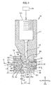
- Fig. 1 shows a sectional view taken along line I-I in Fig. 2.
- Fig. 2 is a front view of a nozzle 10.
- Fig. 1 and Fig. 2 show the bottom half of the drawing in an enlarged manner, to describe the structure of an inflow channel.
- directions in Fig. 1 and Fig. 3 are called as follows: left direction as “front”, right direction as “rear”, upwards direction as “up”, and downwards direction as “down” (or bottom).
- the right direction and left direction are called “right” and "left", respectively.
- a nozzle 10 includes: a main body 11; a buffer chamber 29 provided in the main body 11, whose central axis is an axis line 28 that is the central line of a jet stream J of the liquid; a constrictor part 35 for ejecting the liquid, provided in a plane 291 of the buffer chamber 29 on a front side thereof as one side of a direction of the axis line 28 and whose central axis is the axis line 28; a disk plate 30 provided inside the buffer chamber 29, the disk plate 30 facing the plane 291 of the buffer chamber 29 on the front side thereof and whose center axis is the axis line 28; a supporting member 31 for supporting the disk plate 30 within the buffer chamber 29; a supply opening 121 provided in the main body 11 for supplying the liquid; and an inflow channel 12 provided along a direction different from an extending direction of the axis line 28, the inflow channel 12 opened on a side rear of the disk plate 30 of the buffer chamber 29, which rear side serves as the other side, and which inflow channel 12 communicate
- the main body 11 is a substantially rectangular parallelepiped block.
- the supply opening 121 for supplying the liquid to be ejected is provided in an upper part of the main body 11.
- the axis line 28 lies in a lateral direction (in the embodiment, a front-rear direction) in a lower part of the main body, which axis line 28 is the center through which the liquid is ejected.
- the buffer chamber 29 is provided in the center of the lower part of the main body 11.
- an insertion hole 36 is provided, which insertion hole 36 has a step of a smaller diameter.
- the front side of the lower part of the main body is partially cut out, to house a housing 21.
- the main body 11 is made of material that is corrosion-resistant to liquid and that can resist pressure of the fluid, such as austenitic stainless steel and precipitation hardening stainless steel.
- the inflow channel 12 is provided in the main body 11.
- the supply opening 121 of the inflow channel 12 is provided in the upper part of the main body 11.
- a flow outlet 122 of the inflow channel 12 is provided rear of the disk plate 30 of the buffer chamber 29. Since the flow outlet 122 is provided rear of the disk plate 30, the liquid flown out from the flow outlet 122 to the buffer chamber 29 does not disturb the structure of the flow in the rectification space 292 later described.
- the inflow channel 12 intersects at right angles with the axis line 28.
- a liquid supply means 45 is connected to the supply opening 121 via a pipe.
- an ultrahigh pressure pump may be used, which generates a high pressure of 100 MPa to 500 MPa.
- the inflow channel 12 and the axis line 28 need not to be perpendicular to each other; the inflow channel 12 and the axis line 28 face different directions.
- the buffer chamber 29 is a substantially cylindrical hole provided near the bottom plane (lower of) the main body 11, having the axis line 28 serve as its center.
- the outer shape of the internal space of the buffer chamber 29 is of a cylindrical shape.
- the buffer chamber 29 has a section larger than a section of the inflow channel 12.
- the buffer chamber 29 may be of a barrel shape whose middle part is slightly broadened in diameter. Moreover, corner sections thereof may be rounded.
- the front side of the buffer chamber 29 is opened.
- the constrictor part 35 is provided in a constrictor member 16 shaped of a hollow cylinder whose central axis is the axis line 28.
- the constrictor member 16 is provided so as to close an opening on the front side of the buffer chamber 29.
- the opening of the buffer chamber 29 is closed and liquid sealed by the plane 291 of the constrictor member 16, to obtain a sealed space.
- the plane 291 of the constrictor member 16 defines a plane on the front side of the buffer chamber 29.
- the opening of the buffer chamber 29 in the main body 11 has a tapered plane 27 with a smoothly finished surface. Since the outer shape of the internal space of the buffer chamber 29 is of a cylindrical shape, an inflow channel structure of inside the nozzle 10 becomes extremely compact. Therefore, a nozzle 10 having a small exterior dimension is obtainable.
- the disk plate 30 is provided inside the buffer chamber 29 with the axis line 28 serving as a center thereof, positioned close to the constrictor member 16 but keeping a slight gap L2 provided between the plane 291 of the constrictor member 16.
- the gap L2 is preferably around 1 to 4 times a diameter d of the constrictor part 35.
- a diameter D2 of the disk plate 30 is slightly smaller than a diameter D1 of the buffer chamber 29.
- a cylindrical groove 34 whose central axis is the axis line 28 is provided on a plane of the disk 30 on the front side (the constrictor part 35 side). That is to say, the outer shape of the inner space of the groove 34 is of a cylindrical shape whose central axis is the axis line 28.
- Peripheral edges of the disk plate 30 may be chamfered or rounded.
- the disk plate 30 partitions the buffer chamber 29 into a storage chamber 294 rear of the disk plate 30 and a disk-shaped rectification space 292 that has a rectifying function.
- An annular space between a circumferential plane of the disk plate 30 and an inner circumferential plane of the buffer chamber 29 functions as a communication passage 293 that communicates the storage chamber 294 with the rectification space 292.
- the liquid flows in a flat manner from the storage chamber 294, through the communication passage 293 and from the outer circumference of the rectification space 292 to towards the center, and is ejected from the constrictor part 35.
- the shape of the groove 34 may be a truncated cone shape instead of the cylindrical shape, in which its section broadens as it approaches the constrictor part 35 (front side).
- the change in sectional area in a radial direction of the inflow channel becomes calm, and can further prevent the vortex generation.
- the supporting member 31 is provided on a plane rear of the disk plate 30.
- the supporting member 31 is molded integrally with the disk plate 30.
- the supporting member 31 is a substantially cylindrical member including, in order from the front side, a shaft 311, an insertion section 312, and a screw section 313.
- the shaft 311 is desirably as narrow as possible. If the diameter of the shaft 311 is great, Karman vortex may easily generate on an opposite plane (lower side) of the shaft 311 seen from the flow outlet 122. Therefore, the diameter of the shaft 311 is produced as narrow as possible.
- the main body 11 has an insertion hole 36 provided on the same axis as the axis line 28 and opened on the rear side of the main body 11, which insertion hole 36 communicates with the buffer chamber 29.
- the insertion section 312 fits with and is inserted into the insertion hole 36 of the main body 11. Since the insertion section 312 comes into contact with the step part of the insertion hole 36, the insertion hole 36 can receive the pressure of the liquid within the buffer chamber 29. Therefore, the supporting member 31 will not fall out from the main body 11 from the rear side due to the pressure of the liquid within the buffer chamber 29. Since the insertion section 312 is provided fitting with the insertion hole 36, the supporting member 31 is assembled within the buffer chamber 29 with good accuracy.
- the outer circumference of the insertion section 312 is provided with an annular groove.
- a sealing member 32 is inserted within this annular groove.
- As the sealing member 32 natural rubber, synthetic rubber, a metal O-ring can be used.
- the sealing member 32 seals between the insertion section 312 and the insertion hole 36.
- the screw section 313 protrudes to the rear side of the main body 11, that is, the supporting member 31 is disposed penetrating through the insertion hole 36. Furthermore, the screw section 313 of the supporting member 31 is fixed with a nut that serves as a fixing member.
- a slotted groove, a hexagon socket, two-way taking may be provided on the rear edge of the screw section 313, to prevent the rotation of the supporting member 31 when the nut 33 is tightened to the screw section 313 of the supporting member 31.
- the shaft 311 may be of a shape having a streamline shaped section through which the axis line 28 passes and which reduces the resistance received from the liquid delivered through the inflow channel 12.
- the support member 31 may be configured as having for example a pin or key to restrict the rotation of the supporting member 31.
- the housing 21 includes a reception chamber 18 for containing the constrictor member 16, and a jet stream flow channel 211 provided on the same axis as the axis line 28, which jet stream flow channel 211 is opened on the front side and is communicated with the reception chamber 18.
- the housing 21 is fixed to the main body 11 with a bolt 25 (see Fig. 2 ) that serves as a pressing member.
- the constrictor member 16 includes a smooth flat plane 291 that serves as a wall surface of the buffer chamber 29 on the front side thereof.
- the plane 291 closes the opening of the buffer chamber 29 and defines the plane on the front side of the buffer chamber 29.
- the outer circumferential plane of the constrictor member 16 fits with the inner circumferential plane of the reception chamber 18 of the housing 21.
- the corner sections of the outer circumferential plane with the plane 291 of the constrictor member 16 has a smoothly finished tapered plane 26.
- the vertical angle of the tapered plane 26 is formed the same as or slightly smaller than the vertical angle of the tapered plane 27.
- the constrictor member 16 contained in the reception chamber 18 is sandwiched between the housing 21 and the main body 11. Moreover, by the bolt 25 pressing the housing 21 against the main body 11, the tapered plane 26 of the constrictor member 16 comes into contact with the tapered plane 27 of the main body 11 and is pressed. Therefore, the part between the buffer chamber 29 and the constrictor member 16 is liquid sealed.
- the housing 21 By fastening the housing 21 by using two bolts 25, the housing 21 can be fastened to the main body 11 evenly with respect to the axis line 28. Since the housing 21 is evenly fastened, the constrictor part 35 is fixed on the same axis as the axis line 28.
- the bolt 25 fixes the constrictor member 16 against the pressure of the liquid applied on the buffer chamber 29. Therefore, if the liquid pressure becomes high, excess axial force acts on the bolt 25.
- the tapered plane 27 is provided at the opening of the buffer chamber 29 and the tapered plane 26 is provided at the corner section of the constrictor member 16, it is not limited to this.
- a smooth annular flat plane may be provided around the opening of the buffer chamber 29, and the plane 291 of the constrictor member 16 may be made into contact with this annular flat surface to liquid seal between the constrictor member 16 and the main body 11.
- the constrictor member 16 is securely fixed on the same axis as the axis line 28.
- a hollow cylindrical groove may be provided in the main body 11, so that one part of the outer circumferential plane of the constrictor member 16 is fit with and positioned in the main body 11.
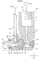
- Fig. 3 shows a sectional view taken along line III-III in Fig. 4.
- Fig 4 is a front view of the nozzle device 100.
- the nozzle device 100 ejects the jet stream J2 in which the liquid and an abrasive are mixed together.
- the nozzle device 100 includes the nozzle 10, a mixing section 40 for mixing the liquid with the abrasive, and an ejection conduit 17.
- Identical members as with the above nozzle 10 are provided with identical reference numerals, and their descriptions are omitted.
- the housing 210 includes an insertion through hole 38 on its front side (outlet side), which insertion through hole 38 is of a hollow cylindrical shape whose central axis is the axis line 28.
- the insertion through hole 38 communicates with the jet stream flow channel 211.
- the housing 210 includes an introduction hole 212 for introducing the abrasive.
- the mixing section 40 is shaped of a hollow cylinder having a void 402 therein, and is inserted into the insertion through hole 38.
- the outer circumferential plane of the mixing section 40 fits with the insertion through hole 38.
- the void 402 communicates with the constrictor part 35 via the jet stream flow channel 211, and is provided on the same axis as the axis line 28.
- the mixing section 40 has an abrasive flow inlet 401 through which the abrasive is flown into along a direction different from the axis line 28.
- a recessed section (back facing hole, or a flat plane provided by cutting out a part of the outer circumferential plane) 403 is provided on an opening outside in a radial direction of the abrasive inlet 401.
- the mixing section 40 is inserted so that the abrasive inlet 401 faces the introduction hole 212.
- An adaptor 41 is attached to the introduction hole 212.
- the adaptor 41 fixes a conduit 42 that serves as a passage for the abrasive.
- the adaptor 41 restricts the rotating direction of the mixing section 40 by being in contact with the bottom plane of the recessed section 403.
- the conduit 42 is connected to an abrasive supply means 46.
- the ejection conduit 17 is of a hollow cylindrical shape, and is inserted inside the insertion through hole 38.
- the ejection conduit 17 is provided in front of and adjacent to the mixing section 40.
- the outer circumferential plane of the ejection conduit 17 fits with the insertion through hole 38. Therefore, the ejection conduit 17 is provided on the same axis as the axis line 28. Since the ejection conduit 17 and the mixing section 40 are fit into the insertion through hole 38 and are disposed on the same axis as the axis line 28, an abrasion amount of the ejection conduit 17 and the mixing section 40 is reduced.
- the ejection conduit 17 and the mixing section 40 may be integrally molded.
- the ejection conduit 17 is fixed by a fixing means 19.
- the fixing means 19 includes a screwing mechanism 191, and an elastic ring 192 disposed surrounding the outer circumference of the ejection conduit 17. By tightening a nut of the screwing mechanism 191, the elastic ring 192 is urged against the outer plane of the ejection conduit 17, and fixes the ejection conduit 17.
- the nozzle 10 of the present embodiment does not have the groove 34 provided in the disk plate 30.
- Fig. 5 to Fig. 7 show a fluid analysis result of the inside of the nozzle of the present Embodiment.
- the fluid analysis is conducted by using ANSYS CFX-15.0 (general purpose thermal fluid analysis software manufactured by ANSYS).
- the analysis uses the finite volume method.
- the fluid is water.
- the boundary conditions is that the fluid is flown into from the inflow channel 12 at a flow rate of 19.3 [gs -1 ], and the outlet of the constrictor part 35 is air-released.
- An inner wall plane is of a No Slip Wall.
- the analysis model is of a steady-state analysis type, and uses the turbulence model.
- the turbulence model uses k- ⁇ model.
- the mesh is of a structured grid.
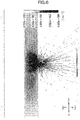
- Fig. 5 represents a flow line map of an analysis result viewed diagonally from a rear side thereof (opposite side to the constrictor part 35).
- the directions of front, rear, left, right, up, and down in Fig. 5 are as shown in the drawing (similarly for Fig. 8 ).
- the flow lines are displayed in gray scale, with a lighter color for a faster velocity, and a darker color for a slower velocity.
- a velocity range exceeding 1.0 ⁇ 10 [ms -1 ] is displayed in white color.
- the range with the slowest velocity is displayed in black.
- the liquid flows into the buffer chamber 29 from the flow outlet 122 at a velocity of 2 to 3 [ms -1 ].
- the shaft 311 is of a cylindrical shape having a diameter of 2 mm, and no large Karman vortex can be seen.
- the fluid flows from the communication passage 293 surrounding the disk plate 30 to the rectification space 292 in front of the disk plate 30, as though the fluid flows around the disk plate 30. At this time, the liquid flows substantially uniformly in a circumferential direction in the communication passage 293. In the rectification space 292, the fluid flows substantially uniformly in the circumferential direction towards the center of the rectification space 292.
- the flow suddenly contracts, is redirected into the axis line direction equally from the entire circumference, and flows into the constrictor part 35.
- the flow rate increases in inverse proportion to a square of a radius of the rectification space 292.
- the velocity reaches a rate of 6.25 to 8.33 ⁇ 10 2 [ms -1 ] that is of the highest velocity (see Fig. 6 ).
- Fig. 6 shows a vector plot diagram showing the velocity of the flow in the I-I section of Fig. 2 .
- the front, rear, up, and down directions in Fig. 6 are as shown in the drawing (similarly for Fig. 9 ).
- Fig. 6 shows a portion of the rectification space 292 in an enlarged manner.
- the size and gradation of the vector represent the velocity.
- the color of the vector is represented in gray scale, and a velocity near 0 [ms -1 ] is represented by a black color and a velocity exceeding 8.33 ⁇ 10 2 [ms -1 ] is represented by a white color.
- the velocity display range is largely different.
- the flow is parallel to the disk plate 30 and is extremely small, at a velocity of 2 to 3 [ms -1 ] (see Fig. 5 ).
- the flow is of a layer form substantially parallel to the disk plate 30 until a position extremely close to the axis 28 (around a diameter of 1 mm), and as the flow approaches the center part, the velocity gradually increases.
- the diameter of 1 mm as the direction of vector of the flow is directed to the center, it gradually tilts (changes) to the constrictor part 35 side, and in a very narrow range in the center, the vector is substantially parallel to the axis line 28.
- This range has a diameter of around 0.1 mm, which is about half of the diameter d of the constrictor part 35.
- the range parallel to the constrictor part 35 is a range of about half of the diameter d of the constrictor part 35, and in the vicinity of the constrictor part 35, the flow flows into the constrictor part 35 in a state still including the velocity in the radial direction.
- the surroundings of the constrictor part are plotted so that the vector is throttled, and the structure of the flow cannot be read well.
- the velocity increases upon approaching the constrictor part 35 from a side close to the disk plate 30 in the direction of the axis line 28, and reaches the maximum speed of 8.33 ⁇ 10 2 [ms -1 ] when passing through the constrictor part.
- Fig. 7 is a contour diagram showing a vorticity in the I-I section of Fig. 2 .
- the front, rear, up, and down directions in Fig. 7 is as shown in the drawing (similarly for Fig. 10 ).
- the vorticity is displayed in gradations of the gray scale; a white color in a case of a high vorticity, and a black color in a case of a low vorticity.
- a point with the lowest vorticity is a position farthest away from the constrictor part 35 in the storage chamber 294, and is displayed in the black color.
- the vorticity appears from mid-degree to relatively high, from the vicinity of the front edge of the flow outlet 122 to the communication passage 293.
- a vortex of a mid-degree is generated in the vicinity of the bottom side (peripheral plane side of the disk plate 30) of the communication passage 293. Furthermore, a vortex is generated on the bottom side (front plane side of the disk plate 30), rear of the rectification space 292 and along the front plane of the disk plate 30, and the vorticity is the highest in the vicinity of the outer edges on the front plane side of the disk plate 30. This vortex gradually decreases upon approach to the center part of the rectification space 292.
- the vortex in the vicinity of the front plane of the disk plate 30 spreads thinly substantially axis symmetrically, having the axis line 27 serving as its center, in the center section of the rectification space 292.
- a vortex is generated thinly and broadly along the plane 291. Furthermore, the vortex is concentrated in a narrow range surrounding the constrictor part 35 in a substantially hemisphere shape. In the vicinity of the radial direction center part of the rectification space 292, the vorticity is slightly low in the cylindrical range from the center part to the rear in the front and rear direction along the axis line 28.
- the liquid flown from the flow outlet 122 into the buffer chamber 29 is received in the storage chamber 294.
- the liquid spreads gently throughout the whole storage chamber 294, and flows out from the communication passage 293 substantially uniformly from its front peripheral sections.
- the liquid flows from the storage chamber 294 to the communication passage 293 circumferentially, substantially uniformly in the axis line 28 direction.
- the liquid flows in from the peripheral sections into the rectification space 292.
- the liquid flows in the rectification space 292, parallel to the disk plate 30 and uniformly in a radial direction, and increasing its velocity toward the center of the rectification space 292.
- the direction of this flow rotates at the center of the rectification space 292, in a corolla shape of a morning glory (morning glory shape) so as to be perpendicular to the disk plate 30.
- the liquid flows into the constrictor part 35 with low turbulence and in high velocity along the axis line 28, with a substantially uniform flow.
- the liquid flowing from the flow outlet 122 to the buffer chamber 29 is received in the storage chamber 294, is spread throughout the entire storage chamber 294, is passed through the communication passage 293 and flowed toward the center from the peripheral section of the rectification space 292, and is contracted toward the constrictor part at the center part of the rectification space 292 and ejected, to obtain a jet stream J with low turbulence.
- a fluid analysis result is shown, according to a nozzle in which a groove 34 is added to the disk plate 30 of the nozzle in Embodiment 1.
- the diameter of the groove 34 is 1.5 mm, and the depth thereof is 0.2 mm.
- Other nozzle shapes and analysis conditions, and further conditions of the diagram drawings are the same as Embodiment 1, and thus detailed descriptions thereof are omitted.
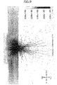
- Fig. 8 shows a flow line map of the analysis results seen diagonally from the rear side.
- the flow line map is substantially the same as Embodiment 1, so detailed descriptions thereof are omitted.
- Fig. 9 is a vector plot diagram showing the velocity of the flow in the I-I section of Fig. 2 .
- the direction of the flow tilts (changes) forwards in the vicinity of the center (a range of 1 mm in diameter).
- a flow parallel to the axis line 28 is generated in a slightly thicker range as compared to Embodiment 1.
- the range of the flow parallel to the axis 28 is of the range having the diameter of 0.2 mm being the same degree as the constrictor part 35.
- the liquid flows along the bottom plane of the groove 34 (parallel to the surface of the disk plate 30).
- the flow parallel to the flat plate 30 once gently spreads as like increasing the width in the axis line 28 direction towards the inside of the groove 34.
- a flow of a layer form parallel to the axis line 28 broadly spread in the radial direction of the axis line 28 as compared to Embodiment 1, is generated.
- the straightness of the jet stream J can be further enhanced than that in Embodiment 1.
- Fig. 10 is a contour diagram showing a vorticity in the I-I section of Fig. 2 .
- an area with a high vorticity is newly generated in the peripheral section of the groove 34.
- a region with low vorticity once spreads in a radial direction by a diameter of 0.3 mm being of the same degree as Embodiment 1 on a front side (disk plate 30 side) for about half of the height (width in the front and rear direction along the axis line 28) of the rectification space 292, and further spreads broadly in the morning glory form across the bottom plane of the groove 34.
- the size of the region reaches to a diameter of about 1 mm at the bottom plane of the groove 34.
- the vorticity is particularly low in the center part of the groove 34.
- a flow is generated directed to the constrictor part 35 as though the liquid is collected in a morning glory form from the space within the groove 34. Further, in the present Embodiment, a flow in a layer form is generated in a range having a large radius as compared to Embodiment 1. Therefore, according to the nozzle of the present Embodiment, the turbulence of the jet stream J ejected from the constrictor part 35 is further small, and thus a jet stream J with high convergence is obtainable.
- a jet stream J having small turbulence and high convergence is obtainable.
- a liquid jet stream J having high straightness and convergence is obtainable, so therefore an abrasion amount of the mixing section 40 and the ejection conduit 17 is reduced.
- the straightness of the jet stream J is high, the energy density of the jet stream J2 in which an abrasive is mixed into the jet stream J is also improved.
- the inner structure can be formed compact, it is possible to reduce the size of the nozzle 10.
- the fluid pressure exceeds 100 MPa, a large inner stress generates on the members that form the surroundings of the flow channel, and may break these members. Therefore, the thickness of the members of the nozzle 10 had to be large to a certain degree.
- the nozzle 10 of the present embodiment is of a simple structure and can configure the flow channel section small, so it is extremely suitable for high pressure fluids.
- the nozzle 10 and nozzle device 100 of the present embodiment is extremely compact, so it is possible to insert inside a bottomed groove section or hole that is subject to work such as processing, and carry out for example work from a side direction different from the inserting direction.
- the distance L3 see Fig. 1 , Fig. 3
- the axis line 28 to the bottom surface of the main body 11 extremely small.
Landscapes
- Engineering & Computer Science (AREA)
- Mechanical Engineering (AREA)
- Physics & Mathematics (AREA)
- Fluid Mechanics (AREA)
- Nozzles (AREA)
Description
- The present invention relates to a nozzle that ejects liquid, and a nozzle device that ejects liquid upon mixing abrasives into a jet stream of the liquid.
- There has been proposed a nozzle to be inserted inside a narrow spot, into which a high pressure fluid is flown along a longitudinal direction, and which ejects fluid including abrasives in a direction different from the longitudinal direction (for example, Japanese Unexamined Patent Publication No.
2013-107202 Figs. 1∼3 )). - In the nozzle disclosed in Japanese Unexamined Patent Publication No.
2013-107202 - In the conventional art, when a high-pressure fluid is redirected, the flow becomes turbulent. A jet stream then ejected from an orifice (constrictor part) provided downstream of the redirector disperses. When the jet stream disperses, the processing ability of the jet stream decreases as compared to a case in which the jet stream is converged.
- Moreover, when an abrasive medium (abrasive) is mixed into the dispersed jet stream and this jet stream including the abrasive medium is ejected, a ejection conduit (ejection pipe) wears intensively. Furthermore, since the jet stream including the abrasive medium is dispersed, the processing ability of the jet stream is low and the processed surface is easily disordered.
- An object of the present invention is to obtain a converged jet stream with a nozzle that ejects liquid, and a nozzle device that ejects liquid upon mixing abrasives into a jet stream of the liquid.
- In view of the above issues, the present invention provides a nozzle adapted to eject liquid as defined in
claim 1. - According to the above configuration, the liquid introduced from the inflow channel spreads throughout the other side of the disk plate (side opposite to the constrictor part) within the buffer chamber, and flows into the one side (constrictor part side) of the disk plate within the buffer chamber from surroundings of the disk plate. The liquid flown into a disk-plate-shaped space formed on the constrictor part side of the disk plate flows from the whole circumference of the disk-plate-shaped space to towards a center part through which the axis line passes substantially equally. The liquid is rectified by passing between the disk plate and a wall of the buffer chamber facing the disk plate. The flow of the liquid gathers into the center part of the disk-plate-shaped space, and suddenly contracts in flow in the axis line direction towards the constrictor part and rotates the direction of the flow. By the liquid ejecting from the disk-plate-shaped space upon passing through the constrictor part, a jet stream with small turbulence is obtainable.
- Moreover, since the flow channel is configured of the buffer chamber and the disk plate supported inside the buffer chamber, the inflow channel is extremely compact, while achieving a high rectifying effect.
- That is to say, according to the present invention, it is possible to obtain a converged jet stream with the nozzle that ejects liquid.
- In the nozzle of the present invention, it is preferable that the buffer chamber has an internal space whose outer shape is of a cylinder.
- Since the outer shape of the internal space of the buffer chamber is cylindrical, the inflow channel structure within the nozzle is extremely compact, and a nozzle with a small exterior dimension is obtainable.
- Here, the term cylindrical is not intended to limit the shape to an exact cylinder based on geometry, and will include, for example, a barrel shape whose middle part is slightly broadened in diameter, and a shape whose part of its corners is rounded.
- In the nozzle of the present invention, it is preferable that the disk plate have a groove provided on a plane of the disk plate on the one side.
- According to the configuration, the disk-plate-shaped space formed between the disk plate and the plane of the buffer chamber facing the disk plate protrude into the other side of the constrictor part. By providing a space into which liquid is supplied in the opposite side of the constrictor part, a strong flow along the axis line generates upstream of the constrictor part, and the degree of vortex generation in the vicinity of the constrictor part (vorticity) decreases. Therefore, a jet stream having further low turbulence is obtainable.
- In the nozzle of the present invention, it is preferable that the groove has an internal space whose outer shape is of a cylinder and whose central axis is the axis line, or of a cone whose section broadens as the internal space approaches the one side.
- According to the above configuration, a jet stream having further low turbulence is obtainable since a strong flow along the axis line generates more uniformly in a circumferential direction upstream of the constrictor part. Moreover, groove formation is easy.
- Here, the term cylindrical shape does not intend to limit the shape to an exact cylinder based on geometry. Similarly, the term conical shape does not limit the shape to an exact cone based on geometry, and may be any shape as long as its lateral section (a section cut at a flat plane perpendicular to the axis line) is shaped as a circle and its vertical section (a section cut at a flat plane including the axis line) is shaped substantially trapezoidal.
- In the nozzle of the present invention, it is preferable that the supporting member have a shaft provided on a plane of the disk plate on the other side, and the shaft be of a cylindrical shape whose central axis is the axis line.
- According to the configuration, since the disk plate is supported by the cylindrical shaft from the opposite side of the constrictor part, the supporting member does not inhibit the flow of the liquid within the buffer chamber. Therefore, the generation of the vortex within the buffer chamber is minimized, and the flow within the disk-plate-shaped space between the disk plate and the wall of the buffer chamber on the constrictor part side facing the disk plate is more rectified. The jet stream ejecting from the constrictor part is largely affected by the turbulence in the liquid on the upstream side of the contraction. Hence, a jet stream with lower turbulence is obtainable by preventing the generation of the vortex within the buffer chamber.
- In the nozzle of the present invention, it is preferable that the supporting member have a shaft provided on a plane of the disk plate on the other side, and the shaft include a streamline shaped section through which the axis line passes and which resistance received from the liquid sent through the inflow channel is reduced.
- According to the configuration, the liquid flowing into the buffer chamber from the inflow channel impinges on the supporting member, and the flow of the liquid does not exfoliate from the surface of the supporting member when separating from the supporting member. Therefore, the generation of a vortex is prevented within the buffer chamber, and a jet stream with lower turbulence is obtainable.
- In the nozzle of the present invention, it is preferable that the one side of the buffer chamber be opened, the constrictor part be provided in a hollow cylindrical constrictor member whose central axis is the axis line, the constrictor member be provided to close the opening on the one side of the buffer chamber, and the nozzle further include a housing having a reception chamber adapted to contain the constrictor member and a jet stream flow channel provided on the same axis as the axis line, the jet stream flow channel opened on the one side and communicated with the reception chamber, and a pressing member adapted to sandwich the constrictor member contained within the reception chamber between the housing and the main body by pressing and fixing the housing toward the main body.
- According to the above configuration, the buffer chamber is configured by opening the one side (constrictor part side) of the buffer chamber and closing the opened side of the buffer chamber with the constrictor member. Therefore, it is easy to produce the constrictor part and the buffer chamber. A plane upstream of the constrictor member that configures the plane of the buffer chamber is externally exposed before being attached to the main body of the constrictor member; it is thus easy to produce this surface smooth.
- Moreover, since the nozzle is configured by containing the constrictor member inside the housing and pressing the housing for fixing the housing to the main body, the constrictor member is easily exchangeable.
- In the nozzle of the present invention, it is preferable that the main body have an insertion hole provided on the same axis as the axis line and opened on the other side of the main body, the insertion hole communicating with the buffer chamber, that the supporting member be disposed passing through the insertion hole, and that the nozzle further includes a sealing member adapted to seal between the supporting member and the insertion hole, and a fixing member adapted to fix the supporting member to the main body from the other side.
- According to the above configuration, the nozzle can be conveniently produced.
- A nozzle device of the present invention is a nozzle device having the nozzle, adapted to eject liquid upon mixing an abrasive into a jet stream of the liquid, the nozzle device including: a hollow cylindrical mixing section provided on the one side of the constrictor part, communicating with the constrictor part and on the same axis as the axis line, the mixing section having an abrasive flow inlet via which the abrasive is flowed into along a direction different from an extending direction of the axis line; and a hollow cylindrical ejection conduit provided on the one side of the mixing section, communicating with the mixing section and on the same axis as the axis line.
- According to the above configuration, a nozzle device is obtainable, which nozzle device uses a jet stream of the liquid from the nozzle with high convergence to mix the abrasive and eject the liquid. Since the convergence of the liquid jet stream is high, the straightness of the jet stream in which the abrasive is mixed is high. Therefore, according to the above configuration, it is possible to prevent the wearing of the ejection conduit caused by the abrasive.
-
-
Fig. 1 shows a longitudinal sectional view of a nozzle in the present embodiment. -
Fig. 2 shows a front view of the nozzle in the present embodiment. -
Fig. 3 shows a longitudinal sectional view of a nozzle device in the present embodiment. -
Fig. 4 shows a front view of the nozzle device in the present embodiment. -
Fig. 5 is a flow line map showing a flow of liquid inside a nozzle inEmbodiment 1. -
Fig. 6 is a vector plot diagram showing a velocity of the flow of liquid inside the nozzle inEmbodiment 1. -
Fig. 7 is a contour diagram showing a vorticity of the flow of liquid inside the nozzle inEmbodiment 1. -
Fig. 8 is a flow line map showing a flow of liquid inside a nozzle in Embodiment 2. -
Fig. 9 is a vector plot diagram showing a velocity of the flow of liquid inside the nozzle in Embodiment 2. -
Fig. 10 is a contour diagram showing a vorticity of the flow of liquid inside the nozzle in Embodiment 2. - According to the present invention, a convergent jet stream is obtainable in a nozzle that ejects liquid and a nozzle device which ejects liquid upon mixing an abrasive into a jet stream of the liquid.
- With reference to the drawings, details of an embodiment of the present invention will be described.
Fig. 1 shows a sectional view taken along line I-I inFig. 2. Fig. 2 is a front view of anozzle 10.Fig. 1 andFig. 2 show the bottom half of the drawing in an enlarged manner, to describe the structure of an inflow channel. In the following descriptions, for convenience, directions inFig. 1 andFig. 3 are called as follows: left direction as "front", right direction as "rear", upwards direction as "up", and downwards direction as "down" (or bottom). Moreover, inFig. 2 andFig. 4 , the right direction and left direction are called "right" and "left", respectively. - A
nozzle 10 includes: amain body 11; abuffer chamber 29 provided in themain body 11, whose central axis is anaxis line 28 that is the central line of a jet stream J of the liquid; aconstrictor part 35 for ejecting the liquid, provided in aplane 291 of thebuffer chamber 29 on a front side thereof as one side of a direction of theaxis line 28 and whose central axis is theaxis line 28; adisk plate 30 provided inside thebuffer chamber 29, thedisk plate 30 facing theplane 291 of thebuffer chamber 29 on the front side thereof and whose center axis is theaxis line 28; a supportingmember 31 for supporting thedisk plate 30 within thebuffer chamber 29; asupply opening 121 provided in themain body 11 for supplying the liquid; and aninflow channel 12 provided along a direction different from an extending direction of theaxis line 28, theinflow channel 12 opened on a side rear of thedisk plate 30 of thebuffer chamber 29, which rear side serves as the other side, and whichinflow channel 12 communicates with thesupply opening 121. - The
main body 11 is a substantially rectangular parallelepiped block. Thesupply opening 121 for supplying the liquid to be ejected is provided in an upper part of themain body 11. Furthermore, theaxis line 28 lies in a lateral direction (in the embodiment, a front-rear direction) in a lower part of the main body, whichaxis line 28 is the center through which the liquid is ejected. Thebuffer chamber 29 is provided in the center of the lower part of themain body 11. On a rear side of the lower part of themain body 11, aninsertion hole 36 is provided, whichinsertion hole 36 has a step of a smaller diameter. The front side of the lower part of the main body is partially cut out, to house ahousing 21. Themain body 11 is made of material that is corrosion-resistant to liquid and that can resist pressure of the fluid, such as austenitic stainless steel and precipitation hardening stainless steel. - The
inflow channel 12 is provided in themain body 11. Thesupply opening 121 of theinflow channel 12 is provided in the upper part of themain body 11. Aflow outlet 122 of theinflow channel 12 is provided rear of thedisk plate 30 of thebuffer chamber 29. Since theflow outlet 122 is provided rear of thedisk plate 30, the liquid flown out from theflow outlet 122 to thebuffer chamber 29 does not disturb the structure of the flow in therectification space 292 later described. Theinflow channel 12 intersects at right angles with theaxis line 28. A liquid supply means 45 is connected to thesupply opening 121 via a pipe. As the liquid supply means 45, an ultrahigh pressure pump may be used, which generates a high pressure of 100 MPa to 500 MPa. - The
inflow channel 12 and theaxis line 28 need not to be perpendicular to each other; theinflow channel 12 and theaxis line 28 face different directions. - The
buffer chamber 29 is a substantially cylindrical hole provided near the bottom plane (lower of) themain body 11, having theaxis line 28 serve as its center. The outer shape of the internal space of thebuffer chamber 29 is of a cylindrical shape. Thebuffer chamber 29 has a section larger than a section of theinflow channel 12. Thebuffer chamber 29 may be of a barrel shape whose middle part is slightly broadened in diameter. Moreover, corner sections thereof may be rounded. - The front side of the
buffer chamber 29 is opened. Theconstrictor part 35 is provided in aconstrictor member 16 shaped of a hollow cylinder whose central axis is theaxis line 28. Theconstrictor member 16 is provided so as to close an opening on the front side of thebuffer chamber 29. The opening of thebuffer chamber 29 is closed and liquid sealed by theplane 291 of theconstrictor member 16, to obtain a sealed space. Theplane 291 of theconstrictor member 16 defines a plane on the front side of thebuffer chamber 29. The opening of thebuffer chamber 29 in themain body 11 has a taperedplane 27 with a smoothly finished surface. Since the outer shape of the internal space of thebuffer chamber 29 is of a cylindrical shape, an inflow channel structure of inside thenozzle 10 becomes extremely compact. Therefore, anozzle 10 having a small exterior dimension is obtainable. - The
disk plate 30 is provided inside thebuffer chamber 29 with theaxis line 28 serving as a center thereof, positioned close to theconstrictor member 16 but keeping a slight gap L2 provided between theplane 291 of theconstrictor member 16. The gap L2 is preferably around 1 to 4 times a diameter d of theconstrictor part 35. A diameter D2 of thedisk plate 30 is slightly smaller than a diameter D1 of thebuffer chamber 29. Preferably, acylindrical groove 34 whose central axis is theaxis line 28 is provided on a plane of thedisk 30 on the front side (theconstrictor part 35 side). That is to say, the outer shape of the inner space of thegroove 34 is of a cylindrical shape whose central axis is theaxis line 28. Peripheral edges of thedisk plate 30 may be chamfered or rounded. Thedisk plate 30 partitions thebuffer chamber 29 into astorage chamber 294 rear of thedisk plate 30 and a disk-shapedrectification space 292 that has a rectifying function. An annular space between a circumferential plane of thedisk plate 30 and an inner circumferential plane of thebuffer chamber 29 functions as acommunication passage 293 that communicates thestorage chamber 294 with therectification space 292. The liquid flows in a flat manner from thestorage chamber 294, through thecommunication passage 293 and from the outer circumference of therectification space 292 to towards the center, and is ejected from theconstrictor part 35. - The shape of the
groove 34 may be a truncated cone shape instead of the cylindrical shape, in which its section broadens as it approaches the constrictor part 35 (front side). In the case of a truncated cone shape, the change in sectional area in a radial direction of the inflow channel becomes calm, and can further prevent the vortex generation. - The supporting
member 31 is provided on a plane rear of thedisk plate 30. The supportingmember 31 is molded integrally with thedisk plate 30. The supportingmember 31 is a substantially cylindrical member including, in order from the front side, ashaft 311, aninsertion section 312, and ascrew section 313. Theshaft 311 is desirably as narrow as possible. If the diameter of theshaft 311 is great, Karman vortex may easily generate on an opposite plane (lower side) of theshaft 311 seen from theflow outlet 122. Therefore, the diameter of theshaft 311 is produced as narrow as possible. - The
main body 11 has aninsertion hole 36 provided on the same axis as theaxis line 28 and opened on the rear side of themain body 11, whichinsertion hole 36 communicates with thebuffer chamber 29. Theinsertion section 312 fits with and is inserted into theinsertion hole 36 of themain body 11. Since theinsertion section 312 comes into contact with the step part of theinsertion hole 36, theinsertion hole 36 can receive the pressure of the liquid within thebuffer chamber 29. Therefore, the supportingmember 31 will not fall out from themain body 11 from the rear side due to the pressure of the liquid within thebuffer chamber 29. Since theinsertion section 312 is provided fitting with theinsertion hole 36, the supportingmember 31 is assembled within thebuffer chamber 29 with good accuracy. - The outer circumference of the
insertion section 312 is provided with an annular groove. A sealingmember 32 is inserted within this annular groove. As the sealingmember 32, natural rubber, synthetic rubber, a metal O-ring can be used. The sealingmember 32 seals between theinsertion section 312 and theinsertion hole 36. Thescrew section 313 protrudes to the rear side of themain body 11, that is, the supportingmember 31 is disposed penetrating through theinsertion hole 36. Furthermore, thescrew section 313 of the supportingmember 31 is fixed with a nut that serves as a fixing member. A slotted groove, a hexagon socket, two-way taking may be provided on the rear edge of thescrew section 313, to prevent the rotation of the supportingmember 31 when thenut 33 is tightened to thescrew section 313 of the supportingmember 31. - Instead of the cylindrical shape, the
shaft 311 may be of a shape having a streamline shaped section through which theaxis line 28 passes and which reduces the resistance received from the liquid delivered through theinflow channel 12. In this case, thesupport member 31 may be configured as having for example a pin or key to restrict the rotation of the supportingmember 31. - The
housing 21 includes areception chamber 18 for containing theconstrictor member 16, and a jetstream flow channel 211 provided on the same axis as theaxis line 28, which jetstream flow channel 211 is opened on the front side and is communicated with thereception chamber 18. Thehousing 21 is fixed to themain body 11 with a bolt 25 (seeFig. 2 ) that serves as a pressing member. - The
constrictor member 16 includes a smoothflat plane 291 that serves as a wall surface of thebuffer chamber 29 on the front side thereof. When thenozzle 10 is assembled, theplane 291 closes the opening of thebuffer chamber 29 and defines the plane on the front side of thebuffer chamber 29. The outer circumferential plane of theconstrictor member 16 fits with the inner circumferential plane of thereception chamber 18 of thehousing 21. Moreover, the corner sections of the outer circumferential plane with theplane 291 of theconstrictor member 16 has a smoothly finished taperedplane 26. The vertical angle of the taperedplane 26 is formed the same as or slightly smaller than the vertical angle of the taperedplane 27. - By the
bolt 25 pressing and fixing thehousing 21 against themain body 11, theconstrictor member 16 contained in thereception chamber 18 is sandwiched between thehousing 21 and themain body 11. Moreover, by thebolt 25 pressing thehousing 21 against themain body 11, the taperedplane 26 of theconstrictor member 16 comes into contact with the taperedplane 27 of themain body 11 and is pressed. Therefore, the part between thebuffer chamber 29 and theconstrictor member 16 is liquid sealed. By fastening thehousing 21 by using twobolts 25, thehousing 21 can be fastened to themain body 11 evenly with respect to theaxis line 28. Since thehousing 21 is evenly fastened, theconstrictor part 35 is fixed on the same axis as theaxis line 28. Furthermore, thebolt 25 fixes theconstrictor member 16 against the pressure of the liquid applied on thebuffer chamber 29. Therefore, if the liquid pressure becomes high, excess axial force acts on thebolt 25. By using twobolts 25 in the horizontal directions, it is possible to reduce the axial diameter of thebolt 25. Therefore, it is possible to reduce a length L3 from theaxis line 28 to the bottom plane of themain body 11. - Although the tapered
plane 27 is provided at the opening of thebuffer chamber 29 and the taperedplane 26 is provided at the corner section of theconstrictor member 16, it is not limited to this. For example, instead of this, a smooth annular flat plane may be provided around the opening of thebuffer chamber 29, and theplane 291 of theconstrictor member 16 may be made into contact with this annular flat surface to liquid seal between theconstrictor member 16 and themain body 11. In this case, theconstrictor member 16 is securely fixed on the same axis as theaxis line 28. Moreover, a hollow cylindrical groove may be provided in themain body 11, so that one part of the outer circumferential plane of theconstrictor member 16 is fit with and positioned in themain body 11. - Next described with reference to
Fig. 3 andFig. 4 is anozzle device 100 that ejects a jet stream J2 in which an abrasive is mixed into a jet stream J of the liquid (seeFig. 1 ).Fig. 3 shows a sectional view taken along line III-III inFig. 4. Fig 4 is a front view of thenozzle device 100. - The
nozzle device 100 ejects the jet stream J2 in which the liquid and an abrasive are mixed together. Thenozzle device 100 includes thenozzle 10, amixing section 40 for mixing the liquid with the abrasive, and anejection conduit 17. Identical members as with theabove nozzle 10 are provided with identical reference numerals, and their descriptions are omitted. - The
housing 210 includes an insertion throughhole 38 on its front side (outlet side), which insertion throughhole 38 is of a hollow cylindrical shape whose central axis is theaxis line 28. The insertion throughhole 38 communicates with the jetstream flow channel 211. Thehousing 210 includes anintroduction hole 212 for introducing the abrasive. - The mixing
section 40 is shaped of a hollow cylinder having a void 402 therein, and is inserted into the insertion throughhole 38. The outer circumferential plane of the mixingsection 40 fits with the insertion throughhole 38. Thevoid 402 communicates with theconstrictor part 35 via the jetstream flow channel 211, and is provided on the same axis as theaxis line 28. The mixingsection 40 has anabrasive flow inlet 401 through which the abrasive is flown into along a direction different from theaxis line 28. A recessed section (back facing hole, or a flat plane provided by cutting out a part of the outer circumferential plane) 403 is provided on an opening outside in a radial direction of theabrasive inlet 401. The mixingsection 40 is inserted so that theabrasive inlet 401 faces theintroduction hole 212. - An
adaptor 41 is attached to theintroduction hole 212. Theadaptor 41 fixes aconduit 42 that serves as a passage for the abrasive. Theadaptor 41 restricts the rotating direction of the mixingsection 40 by being in contact with the bottom plane of the recessedsection 403. Theconduit 42 is connected to an abrasive supply means 46. - The
ejection conduit 17 is of a hollow cylindrical shape, and is inserted inside the insertion throughhole 38. Theejection conduit 17 is provided in front of and adjacent to themixing section 40. The outer circumferential plane of theejection conduit 17 fits with the insertion throughhole 38. Therefore, theejection conduit 17 is provided on the same axis as theaxis line 28. Since theejection conduit 17 and themixing section 40 are fit into the insertion throughhole 38 and are disposed on the same axis as theaxis line 28, an abrasion amount of theejection conduit 17 and themixing section 40 is reduced. Theejection conduit 17 and themixing section 40 may be integrally molded. - The
ejection conduit 17 is fixed by a fixing means 19. The fixing means 19 includes a screwingmechanism 191, and anelastic ring 192 disposed surrounding the outer circumference of theejection conduit 17. By tightening a nut of the screwingmechanism 191, theelastic ring 192 is urged against the outer plane of theejection conduit 17, and fixes theejection conduit 17. - Hereinafter, a structure of the flow of the liquid within the
nozzle 10 of the present embodiment will be described in detail, based on fluid analysis results in two more specific Embodiments. - The Embodiments hereinafter are used for describing the effects of the present invention, and the technical scope of the present invention will not be limited by the following embodiments.
- D1 is an inner diameter (diameter) of the
buffer chamber 29, L1 is a length of the buffer chamber, D2 is an outer diameter (diameter) of thedisk plate 30, t is a thickness of thedisk plate 30, L2 is a distance between thedisk plate 30 and theplane 291, and d is an inner diameter (diameter) of theconstrictor part 35.Embodiment 1 is thenozzle 10 of the present embodiment, and is anozzle 10 whose dimensions are: D1 = 6 mm, L1 = 5 mm, D2 = 5 mm, t = 0.75 mm, L2 = 0.5 mm, d = 0.2 mm. Thenozzle 10 of the present embodiment does not have thegroove 34 provided in thedisk plate 30. -
Fig. 5 to Fig. 7 show a fluid analysis result of the inside of the nozzle of the present Embodiment. The fluid analysis is conducted by using ANSYS CFX-15.0 (general purpose thermal fluid analysis software manufactured by ANSYS). The analysis uses the finite volume method. The fluid is water. The boundary conditions is that the fluid is flown into from theinflow channel 12 at a flow rate of 19.3 [gs-1], and the outlet of theconstrictor part 35 is air-released. An inner wall plane is of a No Slip Wall. The analysis model is of a steady-state analysis type, and uses the turbulence model. The turbulence model uses k-ε model. The mesh is of a structured grid. -
Fig. 5 represents a flow line map of an analysis result viewed diagonally from a rear side thereof (opposite side to the constrictor part 35). The directions of front, rear, left, right, up, and down inFig. 5 are as shown in the drawing (similarly forFig. 8 ). The flow lines are displayed in gray scale, with a lighter color for a faster velocity, and a darker color for a slower velocity. A velocity range exceeding 1.0 × 10 [ms-1] is displayed in white color. The range with the slowest velocity is displayed in black. The liquid flows into thebuffer chamber 29 from theflow outlet 122 at a velocity of 2 to 3 [ms-1]. The fluid gently spreads throughout the internal space of thestorage chamber 294 at a velocity of 1 to 3 [ms-1], which is a lower velocity than the flow rate of theinflow channel 12. In the present Embodiment, theshaft 311 is of a cylindrical shape having a diameter of 2 mm, and no large Karman vortex can be seen. The fluid flows from thecommunication passage 293 surrounding thedisk plate 30 to therectification space 292 in front of thedisk plate 30, as though the fluid flows around thedisk plate 30. At this time, the liquid flows substantially uniformly in a circumferential direction in thecommunication passage 293. In therectification space 292, the fluid flows substantially uniformly in the circumferential direction towards the center of therectification space 292. At the center of therectification space 292, the flow suddenly contracts, is redirected into the axis line direction equally from the entire circumference, and flows into theconstrictor part 35. Inside therectification space 292, the flow rate increases in inverse proportion to a square of a radius of therectification space 292. In the center part of therectification space 292, the velocity reaches a rate of 6.25 to 8.33 × 10² [ms-1] that is of the highest velocity (seeFig. 6 ). -
Fig. 6 shows a vector plot diagram showing the velocity of the flow in the I-I section ofFig. 2 . The front, rear, up, and down directions inFig. 6 are as shown in the drawing (similarly forFig. 9 ).Fig. 6 shows a portion of therectification space 292 in an enlarged manner. The size and gradation of the vector represent the velocity. The color of the vector is represented in gray scale, and a velocity near 0 [ms-1] is represented by a black color and a velocity exceeding 8.33 × 10² [ms-1] is represented by a white color. WithFig. 5 andFig. 6 , the velocity display range is largely different. At a position away from theaxis line 28, the flow is parallel to thedisk plate 30 and is extremely small, at a velocity of 2 to 3 [ms-1] (seeFig. 5 ). The flow is of a layer form substantially parallel to thedisk plate 30 until a position extremely close to the axis 28 (around a diameter of 1 mm), and as the flow approaches the center part, the velocity gradually increases. In a range of the diameter of 1 mm, as the direction of vector of the flow is directed to the center, it gradually tilts (changes) to theconstrictor part 35 side, and in a very narrow range in the center, the vector is substantially parallel to theaxis line 28. This range has a diameter of around 0.1 mm, which is about half of the diameter d of theconstrictor part 35. The range parallel to theconstrictor part 35 is a range of about half of the diameter d of theconstrictor part 35, and in the vicinity of theconstrictor part 35, the flow flows into theconstrictor part 35 in a state still including the velocity in the radial direction. - The surroundings of the constrictor part are plotted so that the vector is throttled, and the structure of the flow cannot be read well. On the rear side of the
constrictor part 35, the velocity increases upon approaching theconstrictor part 35 from a side close to thedisk plate 30 in the direction of theaxis line 28, and reaches the maximum speed of 8.33 × 10² [ms-1] when passing through the constrictor part. -
Fig. 7 is a contour diagram showing a vorticity in the I-I section ofFig. 2 . The front, rear, up, and down directions inFig. 7 is as shown in the drawing (similarly forFig. 10 ). The vorticity is displayed in gradations of the gray scale; a white color in a case of a high vorticity, and a black color in a case of a low vorticity. A point with the lowest vorticity is a position farthest away from theconstrictor part 35 in thestorage chamber 294, and is displayed in the black color. The vorticity appears from mid-degree to relatively high, from the vicinity of the front edge of theflow outlet 122 to thecommunication passage 293. Furthermore, a vortex of a mid-degree is generated in the vicinity of the bottom side (peripheral plane side of the disk plate 30) of thecommunication passage 293. Furthermore, a vortex is generated on the bottom side (front plane side of the disk plate 30), rear of therectification space 292 and along the front plane of thedisk plate 30, and the vorticity is the highest in the vicinity of the outer edges on the front plane side of thedisk plate 30. This vortex gradually decreases upon approach to the center part of therectification space 292. The vortex in the vicinity of the front plane of thedisk plate 30 spreads thinly substantially axis symmetrically, having theaxis line 27 serving as its center, in the center section of therectification space 292. In the front of therectification space 292, a vortex is generated thinly and broadly along theplane 291. Furthermore, the vortex is concentrated in a narrow range surrounding theconstrictor part 35 in a substantially hemisphere shape. In the vicinity of the radial direction center part of therectification space 292, the vorticity is slightly low in the cylindrical range from the center part to the rear in the front and rear direction along theaxis line 28. Moreover, across a narrow range along theaxis line 28 of the radial direction center part of the rectification space 292 (cylindrical range of a diameter 0.04 mm) and across the center part in theaxis line 28 direction (front and rear direction) to thedisk plate 30, a range with a substantially same diameter as the constrictor part 35 (range of the diameter 0.3 mm) hardly has any vortex generated. - As described above, the liquid flown from the
flow outlet 122 into thebuffer chamber 29 is received in thestorage chamber 294. The liquid spreads gently throughout thewhole storage chamber 294, and flows out from thecommunication passage 293 substantially uniformly from its front peripheral sections. The liquid flows from thestorage chamber 294 to thecommunication passage 293 circumferentially, substantially uniformly in theaxis line 28 direction. Furthermore, the liquid flows in from the peripheral sections into therectification space 292. The liquid flows in therectification space 292, parallel to thedisk plate 30 and uniformly in a radial direction, and increasing its velocity toward the center of therectification space 292. The direction of this flow rotates at the center of therectification space 292, in a corolla shape of a morning glory (morning glory shape) so as to be perpendicular to thedisk plate 30. In a cylindrical range having the substantially same diameter as theconstrictor part 35, the liquid flows into theconstrictor part 35 with low turbulence and in high velocity along theaxis line 28, with a substantially uniform flow. - The liquid flowing from the
flow outlet 122 to thebuffer chamber 29 is received in thestorage chamber 294, is spread throughout theentire storage chamber 294, is passed through thecommunication passage 293 and flowed toward the center from the peripheral section of therectification space 292, and is contracted toward the constrictor part at the center part of therectification space 292 and ejected, to obtain a jet stream J with low turbulence. - In the present embodiment, a fluid analysis result is shown, according to a nozzle in which a
groove 34 is added to thedisk plate 30 of the nozzle inEmbodiment 1. The diameter of thegroove 34 is 1.5 mm, and the depth thereof is 0.2 mm. Other nozzle shapes and analysis conditions, and further conditions of the diagram drawings are the same asEmbodiment 1, and thus detailed descriptions thereof are omitted. -
Fig. 8 shows a flow line map of the analysis results seen diagonally from the rear side. The flow line map is substantially the same asEmbodiment 1, so detailed descriptions thereof are omitted. -
Fig. 9 is a vector plot diagram showing the velocity of the flow in the I-I section ofFig. 2 . In the present Embodiment also, the direction of the flow tilts (changes) forwards in the vicinity of the center (a range of 1 mm in diameter). In the space rear of theconstrictor part 35, a flow parallel to theaxis line 28 is generated in a slightly thicker range as compared toEmbodiment 1. The range of the flow parallel to theaxis 28 is of the range having the diameter of 0.2 mm being the same degree as theconstrictor part 35. In the peripheral regions of thegroove 34, the liquid flows along the bottom plane of the groove 34 (parallel to the surface of the disk plate 30). Further, in the vicinity of the center of thegroove 34, a flow in the axis line direction of a velocity of 2.08 × 10² [ms-1] or lower is generated. The liquid flows from theentire groove 34 gathering towards theconstrictor part 35 in a morning glory form. - In the vicinity of the
groove 34 inside therectification space 292, the flow parallel to theflat plate 30 once gently spreads as like increasing the width in theaxis line 28 direction towards the inside of thegroove 34. By the liquid spreading as like increasing the width in the direction of theaxis line 28, a flow of a layer form parallel to theaxis line 28, broadly spread in the radial direction of theaxis line 28 as compared toEmbodiment 1, is generated. By generating a thick flow parallel to theaxis line 28 that is directed to theconstrictor part 35, the straightness of the jet stream J can be further enhanced than that inEmbodiment 1. -
Fig. 10 is a contour diagram showing a vorticity in the I-I section ofFig. 2 . In the present Embodiment, an area with a high vorticity is newly generated in the peripheral section of thegroove 34. However, in the present Embodiment, among the region rear of theconstrictor part 35, a region with low vorticity once spreads in a radial direction by a diameter of 0.3 mm being of the same degree asEmbodiment 1 on a front side (disk plate 30 side) for about half of the height (width in the front and rear direction along the axis line 28) of therectification space 292, and further spreads broadly in the morning glory form across the bottom plane of thegroove 34. The size of the region reaches to a diameter of about 1 mm at the bottom plane of thegroove 34. The vorticity is particularly low in the center part of thegroove 34. - In the nozzle of the present Embodiment, by having the
groove 34 provided in thedisk plate 30, a flow is generated directed to theconstrictor part 35 as though the liquid is collected in a morning glory form from the space within thegroove 34. Further, in the present Embodiment, a flow in a layer form is generated in a range having a large radius as compared toEmbodiment 1. Therefore, according to the nozzle of the present Embodiment, the turbulence of the jet stream J ejected from theconstrictor part 35 is further small, and thus a jet stream J with high convergence is obtainable. - As described above based on the Embodiments, according to the
nozzle 10 of the present embodiment, a jet stream J having small turbulence and high convergence is obtainable. In anozzle device 100 using thenozzle 10, a liquid jet stream J having high straightness and convergence is obtainable, so therefore an abrasion amount of the mixingsection 40 and theejection conduit 17 is reduced. Furthermore, since the straightness of the jet stream J is high, the energy density of the jet stream J2 in which an abrasive is mixed into the jet stream J is also improved. - Moreover, since the inner structure can be formed compact, it is possible to reduce the size of the
nozzle 10. In particular, when the fluid pressure exceeds 100 MPa, a large inner stress generates on the members that form the surroundings of the flow channel, and may break these members. Therefore, the thickness of the members of thenozzle 10 had to be large to a certain degree. Thenozzle 10 of the present embodiment is of a simple structure and can configure the flow channel section small, so it is extremely suitable for high pressure fluids. - The
nozzle 10 andnozzle device 100 of the present embodiment is extremely compact, so it is possible to insert inside a bottomed groove section or hole that is subject to work such as processing, and carry out for example work from a side direction different from the inserting direction. In particular, since there is no structural body on the bottom plane side (deep side seen from the supply opening 121) than thebuffer chamber 29, it is possible to make the distance L3 (seeFig. 1 ,Fig. 3 ) from theaxis line 28 to the bottom surface of themain body 11 extremely small. Reference Signs -
- 10
- nozzle
- 100
- nozzle device
- 11
- main body
- 12
- inflow channel
- 121
- supply opening
- 16
- constrictor member
- 17
- ejection conduit
- 18
- reception chamber
- 19
- fixing means
- 21,210
- housing
- 211
- jet stream flow channel
- 25
- bolt (pressing member)
- 28
- axis line
- 29
- buffer chamber
- 291
- plane
- 30
- disk plate
- 31
- supporting member
- 311
- shaft
- 32
- sealing member
- 33
- nut (fixing member)
- 34
- groove
- 35
- constrictor part
- 36
- insertion hole
- 40
- mixing section
- 401
- abrasive inlet
Claims (9)
- A nozzle (10) adapted to eject liquid, comprising:a main body (11);a buffer chamber (29) provided in the main body (11), whose central axis is an axis line (28) serving as a center line of a jet stream of the liquid;a constrictor part (35) adapted to eject the liquid, provided in a plane of the buffer chamber (29) on one side thereof according to a direction of the axis line (28) and whose central axis is the axis line (28);characterized in that the nozzle (10) further comprisesa disk plate (30) provided inside the buffer chamber (29), a side of the disk plate (30) facing the plane of the buffer chamber (29) on the one side thereof and whose central axis is the axis line (28);a supporting member (31) adapted to support the disk plate (30) within the buffer chamber (29);a supply opening (121) provided in the main body (11), adapted to supply the liquid; andan inflow channel (12) provided along a direction different from an extending direction of the axis line (28), the inflow channel (12) opened on the other side of the disk plate (30) opposite the side of the disk plate (30) facing the plane of the buffer chamber (29) on the one side thereof and communicating with the supply opening (121).
- The nozzle (10) according to claim 1, wherein
the buffer chamber (29) has an internal space whose outer shape is of a cylinder. - The nozzle according to claim 1 or 2, wherein
the disk plate (30) has a groove (34) provided on the plane of the disk plate (30) on the side of the disk plate (30) facing the plane of the buffer chamber (29) on the one side thereof. - The nozzle (10) according to claim 3, wherein
the groove (34) has an internal space whose outer shape is of a cylinder whose central axis is the axis line (28), or of a cone whose section broadens as the internal space approaches the one side of the buffer chamber. - The nozzle (10) according to any one of claims 1 to 4, wherein
the supporting member (31) has a shaft (311) provided on a plane of the disk plate (30) on the other side thereof, and the shaft (311) is of a cylindrical shape whose central axis is the axis line (28). - The nozzle (10) according to any one of claims 1 to 4, wherein
the supporting member (31) has a shaft (311) provided on a plane of the disk plate (30) on the other side thereof, and the shaft (311) includes a streamline-shaped section through which the axis line passes and which resistance received from the liquid sent through the inflow channel (12) is reduced. - The nozzle (10) according to any one of claims 1 to 6, wherein
the one side of the buffer chamber (29) is opened,
the constrictor part (35) is provided in a hollow cylindrical constrictor member (16) whose central axis is the axis line (28),
the constrictor member (16) is provided to close the opening on the one side of the buffer chamber (29), and
the nozzle (10) further comprises:a housing (21) having a reception chamber (18) adapted to contain the constrictor member (16) and a jet stream flow channel (211) provided on the same axis as the axis line (28), the jet stream flow channel (211) opened on the one side of the buffer chamber (29) and communicated with the reception chamber (18); anda pressing member (25) adapted to sandwich the constrictor member (16) contained within the reception chamber (18) between the housing (21) and the main body (11) by pressing and fixing the housing (21) toward the main body (11). - The nozzle (10) according to any one of claims 1 to 7, wherein
the main body (11) has an insertion hole provided on the same axis as the axis line (28) and opened on the other side of the main body (11) opposite the one side of the buffer chamber (29), the insertion hole (36) communicating with the buffer chamber (29),
the supporting member (31) is disposed penetrating through the insertion hole (36), and
the nozzle (10) further comprises:a sealing member (32) adapted to seal between the supporting member (31) and the insertion hole (36); anda fixing member (33) adapted to fix the supporting member (31) to the main body (11) from the other side of the main body (11). - A nozzle device (100) having a nozzle (10) as set forth in any one of claims 1 to 8, the nozzle device (100) adapted to eject liquid upon mixing an abrasive into a jet stream of the liquid, the nozzle device (100) comprising:a hollow cylindrical mixing section (40) provided on the one side of the constrictor part (35), communicating with the constrictor part (35) and on the same axis as the axis line (28), the mixing section (40) having an abrasive flow inlet via which the abrasive is flowed into along a direction different from an extending direction of the axis line (28); anda hollow cylindrical ejection conduit provided on the one side of the mixing section (40), communicating with the mixing section (40) and on the same axis as the axis line (28).
Applications Claiming Priority (1)
| Application Number | Priority Date | Filing Date | Title |
|---|---|---|---|
| JP2015116513A JP6438848B2 (en) | 2015-06-09 | 2015-06-09 | nozzle |
Publications (2)
| Publication Number | Publication Date |
|---|---|
| EP3103588A1 EP3103588A1 (en) | 2016-12-14 |
| EP3103588B1 true EP3103588B1 (en) | 2019-06-05 |
Family
ID=55755334
Family Applications (1)
| Application Number | Title | Priority Date | Filing Date |
|---|---|---|---|
| EP16164081.8A Active EP3103588B1 (en) | 2015-06-09 | 2016-04-06 | Nozzle |
Country Status (3)
| Country | Link |
|---|---|
| US (1) | US10272543B2 (en) |
| EP (1) | EP3103588B1 (en) |
| JP (1) | JP6438848B2 (en) |
Families Citing this family (3)
| Publication number | Priority date | Publication date | Assignee | Title |
|---|---|---|---|---|
| JP6438848B2 (en) * | 2015-06-09 | 2018-12-19 | 株式会社スギノマシン | nozzle |
| CN114248203B (en) * | 2020-09-24 | 2023-04-07 | 中国石油天然气集团有限公司 | Cyclone cutting tool |
| US12059772B2 (en) * | 2021-08-12 | 2024-08-13 | FMG Innovations, LLC | Interchangable fluid jet tool, system, and method for using |
Family Cites Families (38)
| Publication number | Priority date | Publication date | Assignee | Title |
|---|---|---|---|---|
| US2503481A (en) * | 1946-12-04 | 1950-04-11 | William W Hallinan | Atomizing nozzle |
| US2805966A (en) * | 1953-02-19 | 1957-09-10 | Staley Mfg Co A E | Starch pasting process and apparatus |
| US4260110A (en) * | 1977-02-18 | 1981-04-07 | Winfried Werding | Spray nozzle, devices containing the same and apparatus for making such devices |
| US4478368A (en) * | 1982-06-11 | 1984-10-23 | Fluidyne Corporation | High velocity particulate containing fluid jet apparatus and process |
| US4537358A (en) * | 1982-09-27 | 1985-08-27 | U.S. Leisure Incorporated | Nozzle for water tub |
| JPS5969262A (en) * | 1982-10-11 | 1984-04-19 | Fukashi Uragami | Injection-type blast device |
| JPS6313697U (en) * | 1986-07-15 | 1988-01-29 | ||
| US4899937A (en) * | 1986-12-11 | 1990-02-13 | Spraying Systems Co. | Convertible spray nozzle |
| JP2507256B2 (en) * | 1992-07-08 | 1996-06-12 | 川崎重工業株式会社 | Pipe processing method and device |
| JP3086784B2 (en) * | 1996-08-19 | 2000-09-11 | 株式会社不二製作所 | Blasting method and apparatus |
| US6139913A (en) * | 1999-06-29 | 2000-10-31 | National Center For Manufacturing Sciences | Kinetic spray coating method and apparatus |
| DE10009573B4 (en) * | 2000-02-29 | 2006-01-26 | Mabo Steuerungselemente Vertriebs-Gmbh | Nozzle device, in particular arranged in sanitary basins and containers |
| GB0100756D0 (en) * | 2001-01-11 | 2001-02-21 | Powderject Res Ltd | Needleless syringe |
| JP2002227799A (en) * | 2001-02-02 | 2002-08-14 | Honda Motor Co Ltd | Variable flow ejector and fuel cell system equipped with it |
| US6623796B1 (en) * | 2002-04-05 | 2003-09-23 | Delphi Technologies, Inc. | Method of producing a coating using a kinetic spray process with large particles and nozzles for the same |
| US6811812B2 (en) * | 2002-04-05 | 2004-11-02 | Delphi Technologies, Inc. | Low pressure powder injection method and system for a kinetic spray process |
| DE10225304B4 (en) * | 2002-06-07 | 2014-03-27 | Robert Bosch Gmbh | Device for processing component contours |
| US7108893B2 (en) * | 2002-09-23 | 2006-09-19 | Delphi Technologies, Inc. | Spray system with combined kinetic spray and thermal spray ability |
| US6872427B2 (en) * | 2003-02-07 | 2005-03-29 | Delphi Technologies, Inc. | Method for producing electrical contacts using selective melting and a low pressure kinetic spray process |
| US7125586B2 (en) * | 2003-04-11 | 2006-10-24 | Delphi Technologies, Inc. | Kinetic spray application of coatings onto covered materials |
| US7351450B2 (en) * | 2003-10-02 | 2008-04-01 | Delphi Technologies, Inc. | Correcting defective kinetically sprayed surfaces |
| US7335341B2 (en) * | 2003-10-30 | 2008-02-26 | Delphi Technologies, Inc. | Method for securing ceramic structures and forming electrical connections on the same |
| US7475831B2 (en) * | 2004-01-23 | 2009-01-13 | Delphi Technologies, Inc. | Modified high efficiency kinetic spray nozzle |
| US7237308B2 (en) * | 2004-06-10 | 2007-07-03 | North Carolina State University | Composite hydroentangling nozzle strip and method for producing nonwoven fabrics therewith |
| US7900812B2 (en) * | 2004-11-30 | 2011-03-08 | Enerdel, Inc. | Secure physical connections formed by a kinetic spray process |
| DE202005018108U1 (en) * | 2005-11-19 | 2006-01-12 | Hammelmann Maschinenfabrik Gmbh | nozzle head |
| US7934977B2 (en) * | 2007-03-09 | 2011-05-03 | Flow International Corporation | Fluid system and method for thin kerf cutting and in-situ recycling |
| JP2008284524A (en) * | 2007-05-21 | 2008-11-27 | Sugino Mach Ltd | Atomizing apparatus |
| US8448880B2 (en) * | 2007-09-18 | 2013-05-28 | Flow International Corporation | Apparatus and process for formation of laterally directed fluid jets |
| JP4580975B2 (en) * | 2007-12-12 | 2010-11-17 | 本田技研工業株式会社 | Fuel cell system |
| US20110229649A1 (en) * | 2010-03-22 | 2011-09-22 | Baranovski Viatcheslav E | Supersonic material flame spray method and apparatus |
| KR20130087506A (en) * | 2010-06-18 | 2013-08-06 | 캐터필라 모토렌 게엠베하 운트 코. 카게 | Injection nozzle system and ceramic nozzle hood |
| ITMI20112261A1 (en) * | 2011-12-14 | 2013-06-15 | Eni Spa | MULTI-PHASE VARIABLE-SET EJECTOR FOR WELL-HEAD PRODUCTION RECOVERY |
| US8978996B2 (en) * | 2013-03-13 | 2015-03-17 | Gssc, Inc. | System, method, and apparatus for mixing and spraying resin and catalyst |
| JP2015177067A (en) * | 2014-03-14 | 2015-10-05 | 株式会社東芝 | semiconductor device |
| JP6300232B2 (en) * | 2014-09-10 | 2018-03-28 | 株式会社スギノマシン | Channel structure |
| JP6322553B2 (en) * | 2014-11-07 | 2018-05-09 | 株式会社スギノマシン | Abrasive nozzle head |
| JP6438848B2 (en) * | 2015-06-09 | 2018-12-19 | 株式会社スギノマシン | nozzle |
-
2015
- 2015-06-09 JP JP2015116513A patent/JP6438848B2/en active Active
-
2016
- 2016-04-06 EP EP16164081.8A patent/EP3103588B1/en active Active
- 2016-04-06 US US15/092,245 patent/US10272543B2/en active Active
Non-Patent Citations (1)
| Title |
|---|
| None * |
Also Published As
| Publication number | Publication date |
|---|---|
| US10272543B2 (en) | 2019-04-30 |
| JP2017001127A (en) | 2017-01-05 |
| JP6438848B2 (en) | 2018-12-19 |
| EP3103588A1 (en) | 2016-12-14 |
| US20160361795A1 (en) | 2016-12-15 |
Similar Documents
| Publication | Publication Date | Title |
|---|---|---|
| EP3103588B1 (en) | Nozzle | |
| US6571831B1 (en) | Flow regulator | |
| US20180298595A1 (en) | Faucet including an open waterway | |
| US4667700A (en) | Apparatus for throttling flow limitation in water fittings | |
| US3979105A (en) | Valve with improved flow passage | |
| US10294641B2 (en) | Flow rate regulator | |
| US4416301A (en) | Annular piston valve | |
| US10934696B2 (en) | Jet regulator having a slit shaped recess tool engagement surface | |
| EP3442743B1 (en) | Cooling system and machining device | |
| CN101868301A (en) | Water cutting assembly and nozzle nut | |
| CN208696331U (en) | A kind of efficiently cooling interior cryoprobe piece and cutter | |
| US8556226B2 (en) | Valve with the device enhancing capability of its closure member and related seat ring to resist erosion | |
| CN211501654U (en) | Satisfy governing valve that bubble level let out leakage quantity under hard seal | |
| CN201140127Y (en) | Jewel insert applied to nozzle and nozzle with jewel insert | |
| JPS59500729A (en) | liquid flow control assembly | |
| US2915087A (en) | Valves | |
| US9377127B2 (en) | Ball valve with square bore and quarter turn component | |
| CN105736729B (en) | A kind of anti-blocking resistance to erosion two way seal regulating valve | |
| RU93527U1 (en) | TURBINE FLOW METER | |
| Wójtowicz et al. | Influence of design parameters on throttling efficiency of cylindrical and conical vortex valves | |
| CN203488780U (en) | Low-noise cage-type adjusting valve | |
| US20120186683A1 (en) | Adjustable fluid pressure amplifier | |
| CN210753280U (en) | Jet valve core | |
| CN208557175U (en) | Plate cutting Water Cutting device | |
| RU2130809C1 (en) | Nozzle for formation of cutting jet of liquid |
Legal Events
| Date | Code | Title | Description |
|---|---|---|---|
| PUAI | Public reference made under article 153(3) epc to a published international application that has entered the european phase |
Free format text: ORIGINAL CODE: 0009012 |
|
| STAA | Information on the status of an ep patent application or granted ep patent |
Free format text: STATUS: THE APPLICATION HAS BEEN PUBLISHED |
|
| AK | Designated contracting states |
Kind code of ref document: A1 Designated state(s): AL AT BE BG CH CY CZ DE DK EE ES FI FR GB GR HR HU IE IS IT LI LT LU LV MC MK MT NL NO PL PT RO RS SE SI SK SM TR |
|
| AX | Request for extension of the european patent |
Extension state: BA ME |
|
| STAA | Information on the status of an ep patent application or granted ep patent |
Free format text: STATUS: REQUEST FOR EXAMINATION WAS MADE |
|
| 17P | Request for examination filed |
Effective date: 20170531 |
|
| RBV | Designated contracting states (corrected) |
Designated state(s): AL AT BE BG CH CY CZ DE DK EE ES FI FR GB GR HR HU IE IS IT LI LT LU LV MC MK MT NL NO PL PT RO RS SE SI SK SM TR |
|
| REG | Reference to a national code |
Ref country code: DE Ref legal event code: R079 Ref document number: 602016014688 Country of ref document: DE Free format text: PREVIOUS MAIN CLASS: B24C0003320000 Ipc: B05B0007140000 |
|
| GRAP | Despatch of communication of intention to grant a patent |
Free format text: ORIGINAL CODE: EPIDOSNIGR1 |
|
| STAA | Information on the status of an ep patent application or granted ep patent |
Free format text: STATUS: GRANT OF PATENT IS INTENDED |
|
| RIC1 | Information provided on ipc code assigned before grant |
Ipc: B24C 3/32 20060101ALI20190110BHEP Ipc: B05B 7/14 20060101AFI20190110BHEP Ipc: B24C 5/04 20060101ALI20190110BHEP Ipc: B05B 1/34 20060101ALI20190110BHEP |
|
| INTG | Intention to grant announced |
Effective date: 20190206 |
|
| GRAS | Grant fee paid |
Free format text: ORIGINAL CODE: EPIDOSNIGR3 |
|
| GRAA | (expected) grant |
Free format text: ORIGINAL CODE: 0009210 |
|
| STAA | Information on the status of an ep patent application or granted ep patent |
Free format text: STATUS: THE PATENT HAS BEEN GRANTED |
|
| AK | Designated contracting states |
Kind code of ref document: B1 Designated state(s): AL AT BE BG CH CY CZ DE DK EE ES FI FR GB GR HR HU IE IS IT LI LT LU LV MC MK MT NL NO PL PT RO RS SE SI SK SM TR |
|
| REG | Reference to a national code |
Ref country code: GB Ref legal event code: FG4D |
|
| REG | Reference to a national code |
Ref country code: CH Ref legal event code: EP |
|
| REG | Reference to a national code |
Ref country code: AT Ref legal event code: REF Ref document number: 1139468 Country of ref document: AT Kind code of ref document: T Effective date: 20190615 |
|
| REG | Reference to a national code |
Ref country code: IE Ref legal event code: FG4D |
|
| REG | Reference to a national code |
Ref country code: DE Ref legal event code: R096 Ref document number: 602016014688 Country of ref document: DE |
|
| REG | Reference to a national code |
Ref country code: NL Ref legal event code: MP Effective date: 20190605 |
|
| REG | Reference to a national code |
Ref country code: LT Ref legal event code: MG4D |
|
| PG25 | Lapsed in a contracting state [announced via postgrant information from national office to epo] |
Ref country code: NO Free format text: LAPSE BECAUSE OF FAILURE TO SUBMIT A TRANSLATION OF THE DESCRIPTION OR TO PAY THE FEE WITHIN THE PRESCRIBED TIME-LIMIT Effective date: 20190905 Ref country code: LT Free format text: LAPSE BECAUSE OF FAILURE TO SUBMIT A TRANSLATION OF THE DESCRIPTION OR TO PAY THE FEE WITHIN THE PRESCRIBED TIME-LIMIT Effective date: 20190605 Ref country code: ES Free format text: LAPSE BECAUSE OF FAILURE TO SUBMIT A TRANSLATION OF THE DESCRIPTION OR TO PAY THE FEE WITHIN THE PRESCRIBED TIME-LIMIT Effective date: 20190605 Ref country code: HR Free format text: LAPSE BECAUSE OF FAILURE TO SUBMIT A TRANSLATION OF THE DESCRIPTION OR TO PAY THE FEE WITHIN THE PRESCRIBED TIME-LIMIT Effective date: 20190605 Ref country code: SE Free format text: LAPSE BECAUSE OF FAILURE TO SUBMIT A TRANSLATION OF THE DESCRIPTION OR TO PAY THE FEE WITHIN THE PRESCRIBED TIME-LIMIT Effective date: 20190605 Ref country code: AL Free format text: LAPSE BECAUSE OF FAILURE TO SUBMIT A TRANSLATION OF THE DESCRIPTION OR TO PAY THE FEE WITHIN THE PRESCRIBED TIME-LIMIT Effective date: 20190605 Ref country code: FI Free format text: LAPSE BECAUSE OF FAILURE TO SUBMIT A TRANSLATION OF THE DESCRIPTION OR TO PAY THE FEE WITHIN THE PRESCRIBED TIME-LIMIT Effective date: 20190605 |
|
| PG25 | Lapsed in a contracting state [announced via postgrant information from national office to epo] |
Ref country code: LV Free format text: LAPSE BECAUSE OF FAILURE TO SUBMIT A TRANSLATION OF THE DESCRIPTION OR TO PAY THE FEE WITHIN THE PRESCRIBED TIME-LIMIT Effective date: 20190605 Ref country code: RS Free format text: LAPSE BECAUSE OF FAILURE TO SUBMIT A TRANSLATION OF THE DESCRIPTION OR TO PAY THE FEE WITHIN THE PRESCRIBED TIME-LIMIT Effective date: 20190605 Ref country code: GR Free format text: LAPSE BECAUSE OF FAILURE TO SUBMIT A TRANSLATION OF THE DESCRIPTION OR TO PAY THE FEE WITHIN THE PRESCRIBED TIME-LIMIT Effective date: 20190906 Ref country code: BG Free format text: LAPSE BECAUSE OF FAILURE TO SUBMIT A TRANSLATION OF THE DESCRIPTION OR TO PAY THE FEE WITHIN THE PRESCRIBED TIME-LIMIT Effective date: 20190905 |
|
| REG | Reference to a national code |
Ref country code: AT Ref legal event code: MK05 Ref document number: 1139468 Country of ref document: AT Kind code of ref document: T Effective date: 20190605 |
|
| PG25 | Lapsed in a contracting state [announced via postgrant information from national office to epo] |
Ref country code: CZ Free format text: LAPSE BECAUSE OF FAILURE TO SUBMIT A TRANSLATION OF THE DESCRIPTION OR TO PAY THE FEE WITHIN THE PRESCRIBED TIME-LIMIT Effective date: 20190605 Ref country code: RO Free format text: LAPSE BECAUSE OF FAILURE TO SUBMIT A TRANSLATION OF THE DESCRIPTION OR TO PAY THE FEE WITHIN THE PRESCRIBED TIME-LIMIT Effective date: 20190605 Ref country code: PT Free format text: LAPSE BECAUSE OF FAILURE TO SUBMIT A TRANSLATION OF THE DESCRIPTION OR TO PAY THE FEE WITHIN THE PRESCRIBED TIME-LIMIT Effective date: 20191007 Ref country code: SK Free format text: LAPSE BECAUSE OF FAILURE TO SUBMIT A TRANSLATION OF THE DESCRIPTION OR TO PAY THE FEE WITHIN THE PRESCRIBED TIME-LIMIT Effective date: 20190605 Ref country code: AT Free format text: LAPSE BECAUSE OF FAILURE TO SUBMIT A TRANSLATION OF THE DESCRIPTION OR TO PAY THE FEE WITHIN THE PRESCRIBED TIME-LIMIT Effective date: 20190605 Ref country code: NL Free format text: LAPSE BECAUSE OF FAILURE TO SUBMIT A TRANSLATION OF THE DESCRIPTION OR TO PAY THE FEE WITHIN THE PRESCRIBED TIME-LIMIT Effective date: 20190605 Ref country code: EE Free format text: LAPSE BECAUSE OF FAILURE TO SUBMIT A TRANSLATION OF THE DESCRIPTION OR TO PAY THE FEE WITHIN THE PRESCRIBED TIME-LIMIT Effective date: 20190605 |
|
| PG25 | Lapsed in a contracting state [announced via postgrant information from national office to epo] |
Ref country code: SM Free format text: LAPSE BECAUSE OF FAILURE TO SUBMIT A TRANSLATION OF THE DESCRIPTION OR TO PAY THE FEE WITHIN THE PRESCRIBED TIME-LIMIT Effective date: 20190605 Ref country code: IS Free format text: LAPSE BECAUSE OF FAILURE TO SUBMIT A TRANSLATION OF THE DESCRIPTION OR TO PAY THE FEE WITHIN THE PRESCRIBED TIME-LIMIT Effective date: 20191005 Ref country code: IT Free format text: LAPSE BECAUSE OF FAILURE TO SUBMIT A TRANSLATION OF THE DESCRIPTION OR TO PAY THE FEE WITHIN THE PRESCRIBED TIME-LIMIT Effective date: 20190605 |
|
| REG | Reference to a national code |
Ref country code: DE Ref legal event code: R097 Ref document number: 602016014688 Country of ref document: DE |
|
| PG25 | Lapsed in a contracting state [announced via postgrant information from national office to epo] |
Ref country code: TR Free format text: LAPSE BECAUSE OF FAILURE TO SUBMIT A TRANSLATION OF THE DESCRIPTION OR TO PAY THE FEE WITHIN THE PRESCRIBED TIME-LIMIT Effective date: 20190605 |
|
| PLBE | No opposition filed within time limit |
Free format text: ORIGINAL CODE: 0009261 |
|
| STAA | Information on the status of an ep patent application or granted ep patent |
Free format text: STATUS: NO OPPOSITION FILED WITHIN TIME LIMIT |
|
| PG25 | Lapsed in a contracting state [announced via postgrant information from national office to epo] |
Ref country code: PL Free format text: LAPSE BECAUSE OF FAILURE TO SUBMIT A TRANSLATION OF THE DESCRIPTION OR TO PAY THE FEE WITHIN THE PRESCRIBED TIME-LIMIT Effective date: 20190605 Ref country code: DK Free format text: LAPSE BECAUSE OF FAILURE TO SUBMIT A TRANSLATION OF THE DESCRIPTION OR TO PAY THE FEE WITHIN THE PRESCRIBED TIME-LIMIT Effective date: 20190605 |
|
| 26N | No opposition filed |
Effective date: 20200306 |
|
| PG25 | Lapsed in a contracting state [announced via postgrant information from national office to epo] |
Ref country code: SI Free format text: LAPSE BECAUSE OF FAILURE TO SUBMIT A TRANSLATION OF THE DESCRIPTION OR TO PAY THE FEE WITHIN THE PRESCRIBED TIME-LIMIT Effective date: 20190605 |
|
| PG25 | Lapsed in a contracting state [announced via postgrant information from national office to epo] |
Ref country code: MC Free format text: LAPSE BECAUSE OF FAILURE TO SUBMIT A TRANSLATION OF THE DESCRIPTION OR TO PAY THE FEE WITHIN THE PRESCRIBED TIME-LIMIT Effective date: 20190605 |
|
| REG | Reference to a national code |
Ref country code: CH Ref legal event code: PL |
|
| PG25 | Lapsed in a contracting state [announced via postgrant information from national office to epo] |
Ref country code: CH Free format text: LAPSE BECAUSE OF NON-PAYMENT OF DUE FEES Effective date: 20200430 Ref country code: LU Free format text: LAPSE BECAUSE OF NON-PAYMENT OF DUE FEES Effective date: 20200406 Ref country code: LI Free format text: LAPSE BECAUSE OF NON-PAYMENT OF DUE FEES Effective date: 20200430 |
|
| REG | Reference to a national code |
Ref country code: BE Ref legal event code: MM Effective date: 20200430 |
|
| PG25 | Lapsed in a contracting state [announced via postgrant information from national office to epo] |
Ref country code: BE Free format text: LAPSE BECAUSE OF NON-PAYMENT OF DUE FEES Effective date: 20200430 |
|
| PG25 | Lapsed in a contracting state [announced via postgrant information from national office to epo] |
Ref country code: IE Free format text: LAPSE BECAUSE OF NON-PAYMENT OF DUE FEES Effective date: 20200406 |
|
| PG25 | Lapsed in a contracting state [announced via postgrant information from national office to epo] |
Ref country code: MT Free format text: LAPSE BECAUSE OF FAILURE TO SUBMIT A TRANSLATION OF THE DESCRIPTION OR TO PAY THE FEE WITHIN THE PRESCRIBED TIME-LIMIT Effective date: 20190605 Ref country code: CY Free format text: LAPSE BECAUSE OF FAILURE TO SUBMIT A TRANSLATION OF THE DESCRIPTION OR TO PAY THE FEE WITHIN THE PRESCRIBED TIME-LIMIT Effective date: 20190605 |
|
| PG25 | Lapsed in a contracting state [announced via postgrant information from national office to epo] |
Ref country code: MK Free format text: LAPSE BECAUSE OF FAILURE TO SUBMIT A TRANSLATION OF THE DESCRIPTION OR TO PAY THE FEE WITHIN THE PRESCRIBED TIME-LIMIT Effective date: 20190605 |
|
| PGFP | Annual fee paid to national office [announced via postgrant information from national office to epo] |
Ref country code: DE Payment date: 20220620 Year of fee payment: 8 |
|
| PGFP | Annual fee paid to national office [announced via postgrant information from national office to epo] |
Ref country code: GB Payment date: 20240419 Year of fee payment: 9 |
|
| PGFP | Annual fee paid to national office [announced via postgrant information from national office to epo] |
Ref country code: FR Payment date: 20240425 Year of fee payment: 9 |