EP3102969B1 - Automatisiertes ballonstartsystem und verfahren zum starten - Google Patents
Automatisiertes ballonstartsystem und verfahren zum starten Download PDFInfo
- Publication number
- EP3102969B1 EP3102969B1 EP15746021.3A EP15746021A EP3102969B1 EP 3102969 B1 EP3102969 B1 EP 3102969B1 EP 15746021 A EP15746021 A EP 15746021A EP 3102969 B1 EP3102969 B1 EP 3102969B1
- Authority
- EP
- European Patent Office
- Prior art keywords
- balloon
- container
- box
- gas
- launching
- Prior art date
- Legal status (The legal status is an assumption and is not a legal conclusion. Google has not performed a legal analysis and makes no representation as to the accuracy of the status listed.)
- Active
Links
Images



Classifications
-
- B—PERFORMING OPERATIONS; TRANSPORTING
- B64—AIRCRAFT; AVIATION; COSMONAUTICS
- B64B—LIGHTER-THAN AIR AIRCRAFT
- B64B1/00—Lighter-than-air aircraft
- B64B1/005—Arrangements for landing or taking-off, e.g. alighting gear
-
- G—PHYSICS
- G01—MEASURING; TESTING
- G01W—METEOROLOGY
- G01W1/00—Meteorology
- G01W1/08—Adaptations of balloons, missiles, or aircraft for meteorological purposes; Radiosondes
-
- B—PERFORMING OPERATIONS; TRANSPORTING
- B64—AIRCRAFT; AVIATION; COSMONAUTICS
- B64B—LIGHTER-THAN AIR AIRCRAFT
- B64B1/00—Lighter-than-air aircraft
- B64B1/40—Balloons
-
- B—PERFORMING OPERATIONS; TRANSPORTING
- B64—AIRCRAFT; AVIATION; COSMONAUTICS
- B64B—LIGHTER-THAN AIR AIRCRAFT
- B64B1/00—Lighter-than-air aircraft
- B64B1/58—Arrangements or construction of gas-bags; Filling arrangements
- B64B1/62—Controlling gas pressure, heating, cooling, or discharging gas
Definitions
- the present invention relates to an automated balloon launching system. More particularly, the present invention is directed to an automated balloon launching system for launching at least one balloon such as a meteorological balloon or a radiosonde. The present invention also relates to a method for launching at least one balloon such as a meteorological balloon or a radiosonde.
- AU 200247513 discloses a system for filling a balloon, such as a meteorological balloon, with a fluid medium such as gas.
- the system includes a filling nozzle for admitting the medium to the balloon, measurement means for measuring flow of the medium to the filling nozzle and flow control means for controlling the flow of the medium to the filling nozzle.
- the system also includes processing means, responsive to the measurement means, for establishing according to a predetermined criteria when a predetermined amount of the medium has been admitted to the balloon. Upon reaching the predetermined amount, the processing means causes the flow control means to terminate the flow of the medium.
- a method for filling the balloon is also provided.
- KR 102011052835 A teaches an automatic radiosonde gas injecting and fixing apparatus to secure the safety of an operator and supply accurate buoyancy of a sonde by automating a series of a sonde preparing process.
- a weight measuring load cell automatically opens and closes the gas of a radiosonde balloon part.
- An indicator functions the amplification of electric signals.
- An automatic opening and closing unit implements an automatic opening and closing operation according to the electric signals.
- a balloon automatic fastener and forceps are further included in an automatic radiosonde gas injecting apparatus.
- CN 201527483 U discloses a sounding balloon releasing cylinder, which includes a cylinder, top covers, a base and supporting racks.
- the supporting rack is fixed on the base.
- a pair of electrical control devices controlling the top covers to open and close is mounted on the supporting racks on the two sides of the cylinder.
- the electrical control device includes a motor, a worm and worm gear speed reducer and a four linkage-rod transmission mechanism.
- the four linkage-rod transmission mechanism is connected with the left and the right symmetrical and matched top covers, and controls the top covers to open and close.
- a balloon releasing mechanism and a charging nozzle are mounted at the bottom inside the cylinder.
- the sounding balloon releasing cylinder has simple structure, convenient operation and good safety.
- the sounding balloon releasing cylinder can be used for releasing various balloons for detecting the meteorological conditions of high altitude environment or atmospheric environment.
- JP 3841356 B9 teaches a balloon releasing system capable of inflating normally a balloon for observation in a balloon releasing tower to release safely the balloon.
- a gas supply port is provided in a moving-directional tip side, in a tray horizontally movable from a balloon release preparation chamber toward an inside of a cylindrical body through an opening of the cylindrical body in the balloon releasing tower of a chamber adjacent thereto, and an intake port of the balloon for the observation before filling gas is connected disconnectably to the gas supply port.
- a sheet of excellent water repellency is extended in the periphery of the opening on an inner circumferential face of the cylindrical body.
- the equipment comprises a monitoring center and a remote unmanned aerological detection station which perform wireless communication with each other, wherein the unmanned aerological detection station is used for storing and launching an air sounding balloon, and receiving/transmitting air sounding data.
- the monitoring center is used for receiving and processing the aerological detection data returned by the unmanned aerological detection station, and monitoring the operation of the unmanned aerological station.
- the unmanned aerological detection station comprises an equipment shelter, a control computer, a data processing computer, high-wind balloon-releasing equipment, network equipment and the air sounding balloon.
- the control computer performs wireless communication with the monitoring center through the network equipment.
- the control computer controls actions of the heavy-wind balloon-releasing equipment.
- the control computer, the heavy-wind balloon-releasing equipment, the network equipment and the non-inflated air sounding balloon are arranged in the equipment shelter.
- the non-inflated air sounding balloon is launched by the heavy-wind balloon-releasing equipment.
- the equipment can be used for realizing full-automatic operation without human intervention.
- CN 201503503 U discloses an automatic sounding balloon inflating device, which comprises a gas supply source, an inflating valve, a gas supply valve, an inflating amount control unit, an inflating valve control unit and a processing unit, wherein the inflating valve is connected with the gas supply source, and the gas supply valve is arranged between the inflating valve and the gas supply source.
- the inflating amount control unit is arranged between the gas supply source and the gas supply valve to output an inflating amount control signal, and the valve control unit is connected with the inflating valve and sends a first position signal and a second position signal.
- the processing device is connected with the valve control unit, the gas supply valve inflating amount control unit and the inflating valve control unit.
- the utility model can automatically inflate sounding balloons without manual intervention.
- CN 101963677 A describes an atmospheric sounding high-wind ball-releasing system which comprises a cylindrical ball-releasing cylinder, a container top cover, a top cover following system, a top cover starting system, an automatic charging ball system, a dropsonde spinning reel and a ground weather instrument, wherein the top of the ball-releasing cylinder is provided with the container top cover, the ball-releasing cylinder comprises a cover and a rotary bearing arranged on a cylindrical opening, and the cover is arranged at the upper part of the rotary bearing rotating around the ball-releasing cylinder.
- the section of the cover is in a hyperbolic curve.
- the rotary bearing comprises a static rail and a rotating support
- the container top cover is arranged on the rotary bearing
- a drive device of the rotary support is an installed servo motor, after the servo motor obtains wind direction information according to wind direction measured according to the ground dropsonde or the wind direction measured according to a wind pressure sensor, a microprocessor drives the rotary support to rotate according to a set program to ensure that the opening direction of the container top cover faces to the windward direction.
- the top cover opening system comprises a hydraulic pump station, a hydraulic cylinder and a connecting rod.
- a sounding balloon inflating device comprises an inflating nozzle, an air supply source, an executing unit and a processing unit.
- the automatic releasing mechanism for the sounding balloon comprises a locking element, a sliding block and an operating lever.
- the sliding block can sliding along the inflating nozzle and is provided with a first position and a second position.
- the locking element is provided with a clamping hook, is arranged on the periphery of the inflating nozzle and is rotatably connected with the inflating nozzle and the sliding block. When the sliding block slides to the first position, the clamping hook is in clearance fit with the surface of the inflating nozzle.
- the clamping hook When the sliding block slides to the second position, the clamping hook is staggered with the surface of the inflating nozzle.
- the operating lever is installed on the sliding block and is operationally in contact with the executing unit.
- the processing unit When the processing unit outputs a first control signal, the locking element clamps the check valve of the sounding balloon.
- the processing unit outputs a second control signal the locking element releases the check valve of the sounding balloon.
- WO 2010/061034 A1 discloses an arrangement for a launcher for sonde units and a method for launching a sonde unit from a generic launcher.
- the arrangement according to the invention comprises at least one sonde case, which has a generic body for storing a sonde unit, a generic launch base for receiving a sonde case, which launch base has means for launching the sonde unit, generic means for creating a sonde connection between the launcher and a radiosonde, a mechanical adapter, which is arranged to connect to the generic body and the sonde unit, and which is arranged to convert the generic launch means of the launch base to become meteorological-balloon and sonde-specific, as well as an adapter unit, which is arranged to connect to the mechanical adapter, and which is arranged to convert the generic sonde connection to be radiosonde-specific.
- WO 2010/000942 A1 describes an automatic balloon release apparatus for sonde units and a method for automatically releasing sonde units, the balloon release apparatus comprising at least one balloon reserve for storing at least one sonde unit, control means for controlling the filling operation, filling means for filling the balloons of the sonde units of the balloon reserve and release means for releasing the sonde unit.
- the balloon reserve of the apparatus according to the invention is formed of a basket-like matrix, removable as a unit, with gas fill conduits being brought into connection therewith for filling the balloon of each sonde unit.
- the sonde units are stored pre-charged in the balloon reserve prior to release and the sonde unit is released by means of an automatic balloon release apparatus according to the invention.
- the balloon reserve is kept stationary during storage and release. In case of a malfunction the next suitable sonde unit is chosen for release from the balloon reserve.
- US 2005/0006523 A1 teaches an automated balloonsonde launcher and a method for an automated balloonsonde launch.
- the automated balloonsonde launcher may comprise a collapsible protective cover forming an inner region for receiving a balloon, a gas inlet for receiving a gas, a gas outlet for mating with a balloon, a valve operable between the gas inlet and the gas outlet for inflating a balloon within the inner region of the protective cover.
- the launcher further comprises a controller that controls the valve to inflate a balloon within the protective cover, opens an opening in the protective cover and releases a balloon through the opening of the protective cover.
- US 5,895,010 describes a radiosonde balloon launching system including a silo for housing an array of radiosonde balloon modules and for sheltering radiosonde balloons during inflation, a base for containing radiosonde balloon inflation and launch apparatus and a device for shielding the silo until the radiosonde balloons are ready to be launched.
- the automated balloon launcher includes a heated shelter, helium and a "daisy wheel” that holds numerous balloons with attached radiosondes.
- Certain embodiments of the present invention are based on the object to provide an automated balloon launching system. Embodiments of the invention are particularly useful in launching at least one balloon such as a meteorological balloon or a radiosonde. Another object of certain embodiments of the invention is to provide an automated balloon launching system for launching a series of balloons without human intervention. Further, an object of certain embodiments of the invention is to provide a method for launching a balloon.
- an automated balloon launching system for launching at least one balloon such as a meteorological balloon or a radiosonde comprising:
- the system is including at least one storage tank for a gas arranged outside of the container.
- the system is including a gas pipeline arranged outside of the container and connected to the at least one storage tank for gas and to a gas outlet valve arranged in the release silo.
- the system is including a ventilation system in the release silo according to an embodiment.
- the release silo is including a movable protective cover.
- the movable protective cover is preferably comprising two movable members, each movable member having a single rotatory degree of freedom with respect to the release silo.
- the release silo is further comprising means for removing a burst balloon.
- the at least one box or the sonde may be connected to the automated balloon launching system by a galvanic contact.
- the container is including a generator for power generation, at least one photovoltaic module for power generation, a computer system for storing measurement data and/or means for wireless telecommunication.
- the release silo, the means for sealing the opening in the container and/or the at least one storage tank for a gas are arranged to improve safety of an operator.
- the object of embodiments of the invention can be achieved by a method for launching at least one balloon such as a meteorological balloon or a radiosonde comprising the steps of:
- the at least one box including a balloon and a sonde is fed into the storage arranged in the container manually or by the x-, y- and z-manipulator.
- the time interval t can also be dependent on the weather conditions.
- a series of balloons may be released in a continuous process. i.e.
- a first box is removed from the storage, the release silo is fed with the first box, the first balloon is filled with a fluid medium, the first balloon is released, the first box is removed from the release silo and fed into the storage, a second box is removed from the storage, the release silo is fed with the second box, the second balloon is filled with a fluid medium, the second balloon is released, the second box is removed from the release silo and fed into the storage, and so on.
- the fluid medium is comprising hydrogen, helium or methane.
- the mass flow of the fluid medium is measured during filling the balloon for calculating the lift of the balloon.
- the weight of the balloon is preferably measured during and/or after filling the balloon for calculating the lift of the balloon.
- the balloon is filled with the fluid medium until a predetermined lift of the balloon is reached.
- the automated balloon launching system enables automatic launching of at least one balloon.
- the system in particular enables automatic launching of a series of balloons without human intervention.
- the release silo arranged on top of the container improves and secures safety of an operator.
- Arrangement of the release silo, the storage tank for gas and the gas pipeline outside of the container enables use of hydrogen as fluid medium for filling the balloons. Use of hydrogen reduces operational costs of the system. Also any other suitable gas lighter than air can be used for filling the balloons. Balloons are further filled with the fluid medium within the release silo and bursting balloons cannot harm the operator.
- the container is sealed gas tightly after feeding the release silo with a specific box including a balloon and a sonde.
- the system according to the embodiment of the invention can be therefore classified as "EX-safe" (explosion safe).
- Arrangement of the release silo on top of the container eliminates the possibility of a gas flow of a gas lighter than air in a direction downstream into the container.
- a gas flow of a gas lighter than air in a direction upstream from the release silo into the container is not possible.
- explosive gases such as hydrogen are typically used for filling the balloons of a radiosonde for cost reasons
- arrangement of the release silo on top of the container improves safety of the balloon launching system.
- Complex mechanical structures in order to avoid a downstream gas flow into the container are not necessary according to the embodiments of the invention. This reduces, for example, production time of the system, weight of the system, and costs of the system. Additionally, the level of a potential explosion will be above the level of an operator during operation of the balloon launching system.
- systems of the "Ex-safe" type can be used in any environment, for example in security relevant environments such as airports, harbours or industrial plants.
- the release silo also shelters the balloon during inflation, e.g. from wind, rain or snow.
- the automated balloon launching system is further equipped with a generator for power generation or at least one photovoltaic module, a computer system for storing radiosonde measurement data such as temperature or air humidity, and means for wireless telecommunication, autonomous operation of the system is possible and radiosonde measurement data can be transmitted to a control station.
- the automated balloon launching system can be further easily transported, e.g. by truck, ship, plane or railway, to any desired place of installation such as for example an island or a location in an arctic region.
- Fig. 1 a schematic view of an automated balloon launching system 1 for launching at least one balloon 2 such as a meteorological balloon or a radiosonde according to a first embodiment of the invention is shown.
- the at least one box 5 is including a balloon 2 and a sonde 6.
- a release silo 7 is arranged on top of the container 3 for sheltering the balloon 2 during inflation. The release silo 7 may be detachable.
- a x-, y- and z-manipulator 8 which is not shown in Fig.
- the opening 11 in the container 3 may be gas tightly sealed after feeding the release silo 7 with a specific box 5.
- a storage tank 12 for gas e.g. helium or hydrogen
- a gas pipeline 14 arranged outside of the container 3 may be connected to the storage tank 12 for gas and to a gas outlet valve arranged in the release silo 7. Since the gas used is lighter than air, gas cannot flow in a direction upstream from the release silo 7 into the container 3 during filling of a balloon 2. Also the possibility of a gas flow into a direction downstream into the container 3 is eliminated.
- the system 1 may further include a ventilation system for ventilation of the release silo. Gas can be removed from the release silo 7 in case of gas leaking into the release silo 7.
- the system 1 according to the embodiment of the invention can be classified as "EX-safe" and may be for example used in security relevant environments such as airports, harbours or industrial plants.
- the system 1 may include a generator for power generation, a computer system for storing measurement data and/or means for wireless telecommunication.
- the generator for power generation may be for example a gas or fuel generator.
- the gas generator is a hydrogen generator.
- at least one outer surface of the container 3 may be further equipped with at least one photovoltaic module for power generation.
- the system 1 may also include an electrical connection for power supply.
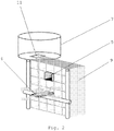
- Fig. 2 a schematic view of a storage rack 9 and a x-, y- and z-manipulator 8 of an automated balloon launching system 1 according to a second embodiment of the invention is illustrated.
- the x-, y- and z-manipulator 8 can handle boxes 5 in x-, y- and z-direction.
- Fig. 3 a schematic view of an automated balloon launching system 1 for launching at least one balloon 2 such as a meteorological balloon or a radiosonde according to a third embodiment of the invention is illustrated.
- the opening 11 in the container 3 may be gas tightly sealed.
- the release silo 7 shelters the balloon 2 during inflation, e.g. from wind, rain or snow.
- a movable protective cover 10 for covering a release opening in the release silo 7 may be in an open or closed position.
- the system 1 according to the embodiment of the invention may include means for measuring the mass flow of gas or the weight of the balloon 2 during filling the balloon 2 with the gas. The measurement data may be used for calculating the lift of the balloon 2.
- the balloon 2 may be filled with the gas until a predetermined lift of the balloon 2 is reached.
- the balloon 2 may be then released through the release opening in the release silo 7. Subsequently the empty box 5 is removed from the release silo 7 by the x-, y- and z-manipulator 8 and fed into the storage 4.
- Fig. 4 a schematic view of a part of the manipulator 8 and a box 5 of an automated balloon launching system 1 according to a fourth embodiment of the invention is illustrated.
- the opening of the container 3 which is not shown in Fig. 4 , may be sealed gas tightly by the ground plate 15 of the manipulator 8.
- a gasket ring may be arranged on the ground plate 15 to seal the opening 11 in the container 3 gas tightly as long as the manipulator 8 exerts a force in z-direction.
- box 5 means a container including a balloon and a sonde.
- this box 5 may be of any shape and can be rigid or elastic.
Landscapes
- Engineering & Computer Science (AREA)
- Aviation & Aerospace Engineering (AREA)
- Environmental & Geological Engineering (AREA)
- Mechanical Engineering (AREA)
- Ecology (AREA)
- Biodiversity & Conservation Biology (AREA)
- Atmospheric Sciences (AREA)
- Environmental Sciences (AREA)
- Life Sciences & Earth Sciences (AREA)
- Filling Or Discharging Of Gas Storage Vessels (AREA)
- Toys (AREA)
- Manipulator (AREA)
- Arrangements For Transmission Of Measured Signals (AREA)
Claims (13)
- Automatisiertes Ballonstartsystem (1) zum Starten mindestens eines Ballons (2), wie etwa eines meteorologischen Ballons oder einer Radiosonde, umfassend:- einen Behälter (3),- ein im Behälter (3) angeordnetes Lager (4) zum Lagern mindestens eines Kastens (5) an einer definierten Lagerposition p = 1, 2, ..., n, wobei der mindestens eine Kasten (5) einen Ballon (2) und eine Sonde (6) enthält,gekennzeichnet durch- ein Freigabesilo (7), das oben auf dem Behälter (3) angeordnet ist, um den Ballon (2) während des Aufblasens zu schützen, und- einen im Behälter (3) angeordneten x-, y- und z-Manipulator (8), wobei der Manipulator konfiguriert ist, um (3) das Lager mit mindestens einem Kasten (5) zu versorgen und/oder einen bestimmten Kasten (5) aus einer der definierten Lagerpositionen p = 1, 2, ..., n zu entfernen und anschließend das Freigabesilo (7) mit dem bestimmten Kasten (5) durch eine Öffnung (11) im Behälter (3) zu versorgen, und- Mittel, die konfiguriert sind, um die Öffnung (11) in dem Behälter (3) gasdicht abzudichten.
- Automatisiertes Ballonstartsystem (1) nach Anspruch 1, wobei das System (1) mindestens einen Lagertank (12) für ein außerhalb des Behälters (3) angeordnetes Gas enthält.
- Automatisiertes Ballonstartsystem (1) nach Anspruch 1 oder 2, wobei das System (1) ein Belüftungssystem (13) im Freigabesilo (7) enthält.
- Automatisiertes Ballonstartsystem (1) nach Anspruch 2, wobei das System (1) eine Gasleitung (14) enthält, die außerhalb des Behälters (3) angeordnet ist und mit dem mindestens einen Lagertank (12) für Gas und einem im Freigabesilo (7) angeordneten Gasauslassventil verbunden ist.
- Automatisiertes Ballonstartsystem (1) nach einem der Ansprüche 1 bis 4, wobei der mindestens eine Kasten (5) oder die Sonde (6) einen RFID-Tag zum Zweck des Identifizierens und Verfolgens des mindestens einen Kastens (5) oder der Sonde (6) an der definierten Lagerposition p = 1, 2, ..., n enthält.
- Automatisiertes Ballonstartsystem (1) nach einem der Ansprüche 1 bis 5, wobei der mindestens eine Kasten (5) oder die Sonde (6) mit dem automatisierten Ballonstartsystem (1) durch einen galvanischen Kontakt verbunden ist.
- Automatisiertes Ballonstartsystem (1) nach einem der Ansprüche 1 bis 6, wobei das System (1) einen Generator zur Stromerzeugung, mindestens ein Photovoltaikmodul zur Stromerzeugung, ein Computersystem zum Speichern von Messdaten und/oder Mittel zur drahtlosen Telekommunikation enthält.
- Verfahren zum Starten mindestens eines Ballons (2), wie etwa eines meteorologischen Ballons oder einer Radiosonde, wobei das Verfahren umfasst:- Zuführen mindestens eines Kastens (5) mit einem Ballon (2) und einer Sonde (6) in ein in einem Behälter (3) angeordnetes Lager (4),- Füllen des Ballons (2) mit einem Fluidmedium, wie etwa einem Gas, das leichter ist als Luft in einem Freigabesilo (7), und- Freigeben des Ballons (2) eines bestimmten Kastens (5) durch eine Freigabeöffnung des Freigabesilos (7),gekennzeichnet durch- Entfernen des bestimmten Kastens (5) aus einer definierten Lagerposition p = 1, 2, ..., n mittels eines im Behälter (3) angeordneten x-, y- und z-Manipulators (8),- Zuführen des oben auf dem Behälter (3) angeordneten Freigabesilos (7) durch eine Öffnung (11) im Behälter (3) mit dem bestimmten Kasten (5) mittels dem x-, y- und z-Manipulator (8), und- gasdichtes Abdichten der Öffnung (11) im Behälter (3) nach dem Zuführen des Freigabesilos (7) durch die Öffnung (11) im Behälter (3) mit dem bestimmten Kasten (5) mittels dem x-, y- und z-Manipulator (8).
- Verfahren nach Anspruch 8, wobei der mindestens eine Kasten (5) mit einem Ballon (2) und einer Sonde (6) in das im Behälter (3) angeordnete Lager (4) manuell oder mittels dem x-, y- und z-Manipulator (8) zugeführt wird.
- Verfahren nach Anspruch 8 oder 9, wobeia) ein zweiter bestimmter Kasten (5) aus einer anderen definierten Speicherposition p = 1, 2, ..., n durch den x-, y- und z-Manipulator (8) nach einem Zeitintervall (t) entfernt wird,b) das Freigabesilo (7) durch die Öffnung (11) im Behälter (3) mit dem zweiten bestimmten Kasten (5) vom x-, y- und z-Manipulator (8) zugeführt wird,c) der Ballon (2) des zweiten bestimmten Kastens (5) mit einem flüssigen Medium, wie etwa einem Gas, das leichter als Luft ist, innerhalb des Freigabesilos (7) gefüllt ist, undd) der Ballon (2) des zweiten bestimmten Kastens (5) durch eine Öffnung im Freigabesilo (7) freigegeben wird.
- Verfahren nach einem der Ansprüche 8 bis 10, wobei das Fluidmedium Wasserstoff, Helium oder Methan umfasst.
- Verfahren nach einem der Ansprüche 8 bis 11, wobei der Massenstrom des Fluidmediums während des Füllens des Ballons (2) zum Berechnen des Auftriebs des Ballons (2) gemessen wird.
- Verfahren nach einem der Ansprüche 8 bis 12, wobei das Gewicht des Ballons (2) während und/oder nach dem Befüllen des Ballons (2) zum Berechnen des Auftriebs des Ballons (2) gemessen wird.
Applications Claiming Priority (2)
| Application Number | Priority Date | Filing Date | Title |
|---|---|---|---|
| FI20145120 | 2014-02-06 | ||
| PCT/FI2015/050073 WO2015118225A1 (en) | 2014-02-06 | 2015-02-06 | Automated balloon launching system and method for launching |
Publications (3)
| Publication Number | Publication Date |
|---|---|
| EP3102969A1 EP3102969A1 (de) | 2016-12-14 |
| EP3102969A4 EP3102969A4 (de) | 2017-09-06 |
| EP3102969B1 true EP3102969B1 (de) | 2019-02-06 |
Family
ID=53777370
Family Applications (1)
| Application Number | Title | Priority Date | Filing Date |
|---|---|---|---|
| EP15746021.3A Active EP3102969B1 (de) | 2014-02-06 | 2015-02-06 | Automatisiertes ballonstartsystem und verfahren zum starten |
Country Status (5)
| Country | Link |
|---|---|
| US (1) | US10246176B2 (de) |
| EP (1) | EP3102969B1 (de) |
| JP (1) | JP6383809B2 (de) |
| CN (1) | CN106133557B (de) |
| WO (1) | WO2015118225A1 (de) |
Families Citing this family (21)
| Publication number | Priority date | Publication date | Assignee | Title |
|---|---|---|---|---|
| CN106133557B (zh) * | 2014-02-06 | 2019-05-10 | 维萨拉公司 | 自动化气球发射系统以及发射方法 |
| EP3407095B1 (de) * | 2016-01-19 | 2020-07-29 | Meisei Electric Co., Ltd. | Kanister und kanistermodul |
| EP3407094B1 (de) * | 2016-01-19 | 2022-01-12 | Meisei Electric Co., Ltd. | Ballonauslösungsvorrichtung |
| CN106741816A (zh) * | 2016-11-25 | 2017-05-31 | 深圳市天地无忧科技有限公司 | 悬浮式机器人 |
| CN106741818B (zh) * | 2016-12-16 | 2023-10-13 | 三一汽车制造有限公司 | 囊体箱及锚泊车 |
| CN106895765A (zh) * | 2017-04-18 | 2017-06-27 | 北京林业大学 | 一种便携式精准测树高的工具 |
| CN108398201B (zh) * | 2018-04-20 | 2024-10-15 | 中国气象局气象探测中心 | 探空气球净举力检测控制装置及其检测控制方法 |
| CN108919383A (zh) * | 2018-06-08 | 2018-11-30 | 中国气象局气象探测中心 | 一种小型自动探空装置及其控制系统、方法 |
| CN108845377A (zh) * | 2018-06-19 | 2018-11-20 | 北京无线电测量研究所 | 一种小型化自动放球系统 |
| DE202018004602U1 (de) | 2018-10-04 | 2019-02-07 | Vaisala Oyj | Anordnung zur Verwendung in einer Vorrichtung zum automatischen Starten von Radiosonden |
| CN110481753B (zh) * | 2019-07-08 | 2022-11-22 | 中国人民解放军63660部队 | 一种高空气球机动式快速发放系统 |
| CN110294095B (zh) * | 2019-07-10 | 2024-06-07 | 青岛飞宇航空科技有限公司 | 一种高空气球发放装置 |
| CN110308500A (zh) * | 2019-07-29 | 2019-10-08 | 北京无线电测量研究所 | 一种小型全自动探空设备 |
| CN110596786B (zh) * | 2019-09-02 | 2024-07-05 | 山东省科学院海洋仪器仪表研究所 | 一种浮标用探空气球自动施放系统 |
| CN110901940B (zh) * | 2019-12-02 | 2021-02-19 | 航天新气象科技有限公司 | 一种超矮型探空气球自动释放装置 |
| CN111983728B (zh) * | 2020-09-22 | 2025-08-26 | 航天新气象科技有限公司 | 一种全自动探空系统远端站、探空装备和远端站探空方法 |
| CN112925043A (zh) * | 2021-01-28 | 2021-06-08 | 南京大桥机器有限公司 | 机器人全自动探空装备 |
| CN112684518B (zh) * | 2021-02-04 | 2025-01-24 | 山西省气象科学研究所 | 基于云计算的机器人高空气象探测装置及系统 |
| CN115468612B (zh) * | 2022-08-29 | 2024-11-26 | 中国科学院空天信息创新研究院 | 球体系统充气量计量方法和球体系统的称重系统 |
| CN115793100B (zh) * | 2022-10-31 | 2023-07-18 | 国网安徽省电力有限公司马鞍山供电公司 | 一种微型环境气象数据采集装置及其方法 |
| WO2026013792A1 (ja) * | 2024-07-10 | 2026-01-15 | Ntt株式会社 | 観測システム |
Family Cites Families (18)
| Publication number | Priority date | Publication date | Assignee | Title |
|---|---|---|---|---|
| US5548283A (en) * | 1994-10-31 | 1996-08-20 | University Corporation For Atmosphere Research | Integrated control system for preparing and deploying sounding devices and managing telemetry therefrom |
| US5636480A (en) * | 1994-10-31 | 1997-06-10 | University Corporation For Atmospheric Research | Facility for preparing and deploying sounding devices |
| US5884862A (en) | 1996-08-02 | 1999-03-23 | Visidyne, Inc. | Automatic radiosonde balloon launching module |
| US5850988A (en) * | 1996-08-20 | 1998-12-22 | Visidyne, Inc. | Radiosonde balloon launching system |
| AU785120B2 (en) * | 2001-06-13 | 2006-09-28 | Engertrol Pty Ltd | Balloon launching system |
| WO2004092774A2 (en) * | 2003-04-11 | 2004-10-28 | Ada Technologies, Inc. | Balloonsonde launcher |
| JP2006036104A (ja) * | 2004-07-29 | 2006-02-09 | Meteorological Agency | 放球装置 |
| JP3841356B2 (ja) | 2004-07-29 | 2006-11-01 | 気象庁長官 | 放球装置 |
| FI124146B (fi) | 2008-07-02 | 2014-03-31 | Vaisala Oyj | Automaattinen pallonpäästölaite ja menetelmä säähavaintopallon automaattiseksi laukaisemiseksi |
| EP2350703B1 (de) * | 2008-11-27 | 2016-06-29 | Vaisala Oyj | Anordnung für eine startvorrichtung meteorologischer ballons und verfahren zum starten von meteorologischen ballons |
| CN201503503U (zh) | 2009-06-10 | 2010-06-09 | 南京大桥机器有限公司 | 探空气球自动充气球装置 |
| CN201449457U (zh) | 2009-06-10 | 2010-05-05 | 南京大桥机器有限公司 | 探空气球自动释放机构 |
| CN201527483U (zh) | 2009-11-11 | 2010-07-14 | 内蒙古自治区大气探测技术保障中心 | 探空气球施放筒 |
| KR20110052835A (ko) | 2009-11-13 | 2011-05-19 | 강주성 | 라디오 존데 자동 가스 주입 및 고정 장치 |
| CN101963677A (zh) | 2010-08-27 | 2011-02-02 | 南京大桥机器有限公司 | 大气探测大风放气球系统 |
| CN102253429B (zh) * | 2011-04-28 | 2013-07-17 | 南京大桥机器有限公司 | 全自动探空装备 |
| CN106133557B (zh) * | 2014-02-06 | 2019-05-10 | 维萨拉公司 | 自动化气球发射系统以及发射方法 |
| US9327844B2 (en) * | 2014-02-13 | 2016-05-03 | Google Inc. | Methods and mechanisms for balloon launching |
-
2015
- 2015-02-06 CN CN201580006636.XA patent/CN106133557B/zh active Active
- 2015-02-06 JP JP2016568139A patent/JP6383809B2/ja active Active
- 2015-02-06 WO PCT/FI2015/050073 patent/WO2015118225A1/en not_active Ceased
- 2015-02-06 EP EP15746021.3A patent/EP3102969B1/de active Active
-
2016
- 2016-08-05 US US15/229,248 patent/US10246176B2/en active Active
Non-Patent Citations (1)
| Title |
|---|
| None * |
Also Published As
| Publication number | Publication date |
|---|---|
| CN106133557A (zh) | 2016-11-16 |
| JP2017506350A (ja) | 2017-03-02 |
| EP3102969A4 (de) | 2017-09-06 |
| CN106133557B (zh) | 2019-05-10 |
| US10246176B2 (en) | 2019-04-02 |
| US20160340015A1 (en) | 2016-11-24 |
| EP3102969A1 (de) | 2016-12-14 |
| JP6383809B2 (ja) | 2018-08-29 |
| WO2015118225A1 (en) | 2015-08-13 |
Similar Documents
| Publication | Publication Date | Title |
|---|---|---|
| US10246176B2 (en) | Automated balloon launching system and method for launching | |
| US5850988A (en) | Radiosonde balloon launching system | |
| CN102253429B (zh) | 全自动探空装备 | |
| GB2529021A (en) | Charging and re-provisioning station for electric and hybrid unmanned aerial vehicles. | |
| US5884862A (en) | Automatic radiosonde balloon launching module | |
| US20140176344A1 (en) | In line inspection method and apparatus for performing in line inspections | |
| CN106005434B (zh) | 一种基于物联网的船载无人机水上行驶保护系统 | |
| US20150122364A1 (en) | Systems and methods for pipeline device propulsion | |
| KR102137316B1 (ko) | 플랜트 검사용 드론봇 장치 | |
| US9964959B2 (en) | Method and apparatus for aircraft inspection | |
| EP2304477B1 (de) | Automatische ballonstartvorrichtung und verfahren zum automatischen start von meteorologischen ballons | |
| CN106080987A (zh) | 海缆水下同步放线潜航器 | |
| CN110244386A (zh) | 一种机载下投式全自动探空吊舱装备及探测方法 | |
| CN108045536A (zh) | 一种无缆小型垂直起降水下机器人及其控制方法 | |
| CN110834699A (zh) | 一种基于海上无人船平台的全天候气象火箭探空设备 | |
| CN112027123B (zh) | 一种自动航行定位的海上卫星发射平台 | |
| CN108845377A (zh) | 一种小型化自动放球系统 | |
| CN112925043A (zh) | 机器人全自动探空装备 | |
| CN109178357B (zh) | 一种空间生命保障装置 | |
| CN211139594U (zh) | 一种基于海上无人船平台的全天候气象火箭探空设备 | |
| KR101420298B1 (ko) | 고층기상관측용 라디오존데 자동 비양 시스템 | |
| CN113847946A (zh) | 一种基于浮标平台的对流层参数剖面探测系统及探测方法 | |
| CN206068118U (zh) | 一种能够长时间置空的信息采集及监控装置 | |
| CN223204819U (zh) | 海上重复使用的运载火箭系统 | |
| CN112684518B (zh) | 基于云计算的机器人高空气象探测装置及系统 |
Legal Events
| Date | Code | Title | Description |
|---|---|---|---|
| PUAI | Public reference made under article 153(3) epc to a published international application that has entered the european phase |
Free format text: ORIGINAL CODE: 0009012 |
|
| STAA | Information on the status of an ep patent application or granted ep patent |
Free format text: STATUS: REQUEST FOR EXAMINATION WAS MADE |
|
| 17P | Request for examination filed |
Effective date: 20160713 |
|
| AK | Designated contracting states |
Kind code of ref document: A1 Designated state(s): AL AT BE BG CH CY CZ DE DK EE ES FI FR GB GR HR HU IE IS IT LI LT LU LV MC MK MT NL NO PL PT RO RS SE SI SK SM TR |
|
| AX | Request for extension of the european patent |
Extension state: BA ME |
|
| DAX | Request for extension of the european patent (deleted) | ||
| A4 | Supplementary search report drawn up and despatched |
Effective date: 20170804 |
|
| RIC1 | Information provided on ipc code assigned before grant |
Ipc: G01W 1/08 20060101AFI20170731BHEP Ipc: B64B 1/40 20060101ALI20170731BHEP Ipc: B64B 1/58 20060101ALI20170731BHEP Ipc: B64B 1/00 20060101ALI20170731BHEP |
|
| STAA | Information on the status of an ep patent application or granted ep patent |
Free format text: STATUS: EXAMINATION IS IN PROGRESS |
|
| 17Q | First examination report despatched |
Effective date: 20180315 |
|
| GRAP | Despatch of communication of intention to grant a patent |
Free format text: ORIGINAL CODE: EPIDOSNIGR1 |
|
| STAA | Information on the status of an ep patent application or granted ep patent |
Free format text: STATUS: GRANT OF PATENT IS INTENDED |
|
| INTG | Intention to grant announced |
Effective date: 20181113 |
|
| GRAS | Grant fee paid |
Free format text: ORIGINAL CODE: EPIDOSNIGR3 |
|
| GRAA | (expected) grant |
Free format text: ORIGINAL CODE: 0009210 |
|
| STAA | Information on the status of an ep patent application or granted ep patent |
Free format text: STATUS: THE PATENT HAS BEEN GRANTED |
|
| AK | Designated contracting states |
Kind code of ref document: B1 Designated state(s): AL AT BE BG CH CY CZ DE DK EE ES FI FR GB GR HR HU IE IS IT LI LT LU LV MC MK MT NL NO PL PT RO RS SE SI SK SM TR |
|
| REG | Reference to a national code |
Ref country code: GB Ref legal event code: FG4D |
|
| REG | Reference to a national code |
Ref country code: CH Ref legal event code: EP Ref country code: AT Ref legal event code: REF Ref document number: 1095257 Country of ref document: AT Kind code of ref document: T Effective date: 20190215 |
|
| REG | Reference to a national code |
Ref country code: IE Ref legal event code: FG4D |
|
| REG | Reference to a national code |
Ref country code: DE Ref legal event code: R096 Ref document number: 602015024367 Country of ref document: DE |
|
| REG | Reference to a national code |
Ref country code: NL Ref legal event code: MP Effective date: 20190206 |
|
| REG | Reference to a national code |
Ref country code: LT Ref legal event code: MG4D |
|
| PG25 | Lapsed in a contracting state [announced via postgrant information from national office to epo] |
Ref country code: LT Free format text: LAPSE BECAUSE OF FAILURE TO SUBMIT A TRANSLATION OF THE DESCRIPTION OR TO PAY THE FEE WITHIN THE PRESCRIBED TIME-LIMIT Effective date: 20190206 Ref country code: NO Free format text: LAPSE BECAUSE OF FAILURE TO SUBMIT A TRANSLATION OF THE DESCRIPTION OR TO PAY THE FEE WITHIN THE PRESCRIBED TIME-LIMIT Effective date: 20190506 Ref country code: NL Free format text: LAPSE BECAUSE OF FAILURE TO SUBMIT A TRANSLATION OF THE DESCRIPTION OR TO PAY THE FEE WITHIN THE PRESCRIBED TIME-LIMIT Effective date: 20190206 Ref country code: PT Free format text: LAPSE BECAUSE OF FAILURE TO SUBMIT A TRANSLATION OF THE DESCRIPTION OR TO PAY THE FEE WITHIN THE PRESCRIBED TIME-LIMIT Effective date: 20190606 Ref country code: SE Free format text: LAPSE BECAUSE OF FAILURE TO SUBMIT A TRANSLATION OF THE DESCRIPTION OR TO PAY THE FEE WITHIN THE PRESCRIBED TIME-LIMIT Effective date: 20190206 Ref country code: FI Free format text: LAPSE BECAUSE OF FAILURE TO SUBMIT A TRANSLATION OF THE DESCRIPTION OR TO PAY THE FEE WITHIN THE PRESCRIBED TIME-LIMIT Effective date: 20190206 |
|
| REG | Reference to a national code |
Ref country code: AT Ref legal event code: MK05 Ref document number: 1095257 Country of ref document: AT Kind code of ref document: T Effective date: 20190206 |
|
| PG25 | Lapsed in a contracting state [announced via postgrant information from national office to epo] |
Ref country code: IS Free format text: LAPSE BECAUSE OF FAILURE TO SUBMIT A TRANSLATION OF THE DESCRIPTION OR TO PAY THE FEE WITHIN THE PRESCRIBED TIME-LIMIT Effective date: 20190606 Ref country code: LV Free format text: LAPSE BECAUSE OF FAILURE TO SUBMIT A TRANSLATION OF THE DESCRIPTION OR TO PAY THE FEE WITHIN THE PRESCRIBED TIME-LIMIT Effective date: 20190206 Ref country code: RS Free format text: LAPSE BECAUSE OF FAILURE TO SUBMIT A TRANSLATION OF THE DESCRIPTION OR TO PAY THE FEE WITHIN THE PRESCRIBED TIME-LIMIT Effective date: 20190206 Ref country code: BG Free format text: LAPSE BECAUSE OF FAILURE TO SUBMIT A TRANSLATION OF THE DESCRIPTION OR TO PAY THE FEE WITHIN THE PRESCRIBED TIME-LIMIT Effective date: 20190506 Ref country code: HR Free format text: LAPSE BECAUSE OF FAILURE TO SUBMIT A TRANSLATION OF THE DESCRIPTION OR TO PAY THE FEE WITHIN THE PRESCRIBED TIME-LIMIT Effective date: 20190206 Ref country code: GR Free format text: LAPSE BECAUSE OF FAILURE TO SUBMIT A TRANSLATION OF THE DESCRIPTION OR TO PAY THE FEE WITHIN THE PRESCRIBED TIME-LIMIT Effective date: 20190507 |
|
| REG | Reference to a national code |
Ref country code: CH Ref legal event code: PL |
|
| PG25 | Lapsed in a contracting state [announced via postgrant information from national office to epo] |
Ref country code: ES Free format text: LAPSE BECAUSE OF FAILURE TO SUBMIT A TRANSLATION OF THE DESCRIPTION OR TO PAY THE FEE WITHIN THE PRESCRIBED TIME-LIMIT Effective date: 20190206 Ref country code: AL Free format text: LAPSE BECAUSE OF FAILURE TO SUBMIT A TRANSLATION OF THE DESCRIPTION OR TO PAY THE FEE WITHIN THE PRESCRIBED TIME-LIMIT Effective date: 20190206 Ref country code: DK Free format text: LAPSE BECAUSE OF FAILURE TO SUBMIT A TRANSLATION OF THE DESCRIPTION OR TO PAY THE FEE WITHIN THE PRESCRIBED TIME-LIMIT Effective date: 20190206 Ref country code: SK Free format text: LAPSE BECAUSE OF FAILURE TO SUBMIT A TRANSLATION OF THE DESCRIPTION OR TO PAY THE FEE WITHIN THE PRESCRIBED TIME-LIMIT Effective date: 20190206 Ref country code: LU Free format text: LAPSE BECAUSE OF NON-PAYMENT OF DUE FEES Effective date: 20190206 Ref country code: EE Free format text: LAPSE BECAUSE OF FAILURE TO SUBMIT A TRANSLATION OF THE DESCRIPTION OR TO PAY THE FEE WITHIN THE PRESCRIBED TIME-LIMIT Effective date: 20190206 Ref country code: CZ Free format text: LAPSE BECAUSE OF FAILURE TO SUBMIT A TRANSLATION OF THE DESCRIPTION OR TO PAY THE FEE WITHIN THE PRESCRIBED TIME-LIMIT Effective date: 20190206 Ref country code: IT Free format text: LAPSE BECAUSE OF FAILURE TO SUBMIT A TRANSLATION OF THE DESCRIPTION OR TO PAY THE FEE WITHIN THE PRESCRIBED TIME-LIMIT Effective date: 20190206 Ref country code: RO Free format text: LAPSE BECAUSE OF FAILURE TO SUBMIT A TRANSLATION OF THE DESCRIPTION OR TO PAY THE FEE WITHIN THE PRESCRIBED TIME-LIMIT Effective date: 20190206 |
|
| REG | Reference to a national code |
Ref country code: DE Ref legal event code: R097 Ref document number: 602015024367 Country of ref document: DE |
|
| REG | Reference to a national code |
Ref country code: BE Ref legal event code: MM Effective date: 20190228 |
|
| REG | Reference to a national code |
Ref country code: IE Ref legal event code: MM4A |
|
| PG25 | Lapsed in a contracting state [announced via postgrant information from national office to epo] |
Ref country code: PL Free format text: LAPSE BECAUSE OF FAILURE TO SUBMIT A TRANSLATION OF THE DESCRIPTION OR TO PAY THE FEE WITHIN THE PRESCRIBED TIME-LIMIT Effective date: 20190206 Ref country code: SM Free format text: LAPSE BECAUSE OF FAILURE TO SUBMIT A TRANSLATION OF THE DESCRIPTION OR TO PAY THE FEE WITHIN THE PRESCRIBED TIME-LIMIT Effective date: 20190206 |
|
| PLBE | No opposition filed within time limit |
Free format text: ORIGINAL CODE: 0009261 |
|
| STAA | Information on the status of an ep patent application or granted ep patent |
Free format text: STATUS: NO OPPOSITION FILED WITHIN TIME LIMIT |
|
| PG25 | Lapsed in a contracting state [announced via postgrant information from national office to epo] |
Ref country code: CH Free format text: LAPSE BECAUSE OF NON-PAYMENT OF DUE FEES Effective date: 20190228 Ref country code: MC Free format text: LAPSE BECAUSE OF FAILURE TO SUBMIT A TRANSLATION OF THE DESCRIPTION OR TO PAY THE FEE WITHIN THE PRESCRIBED TIME-LIMIT Effective date: 20190206 Ref country code: LI Free format text: LAPSE BECAUSE OF NON-PAYMENT OF DUE FEES Effective date: 20190228 Ref country code: AT Free format text: LAPSE BECAUSE OF FAILURE TO SUBMIT A TRANSLATION OF THE DESCRIPTION OR TO PAY THE FEE WITHIN THE PRESCRIBED TIME-LIMIT Effective date: 20190206 |
|
| 26N | No opposition filed |
Effective date: 20191107 |
|
| GBPC | Gb: european patent ceased through non-payment of renewal fee |
Effective date: 20190506 |
|
| PG25 | Lapsed in a contracting state [announced via postgrant information from national office to epo] |
Ref country code: IE Free format text: LAPSE BECAUSE OF NON-PAYMENT OF DUE FEES Effective date: 20190206 |
|
| PG25 | Lapsed in a contracting state [announced via postgrant information from national office to epo] |
Ref country code: BE Free format text: LAPSE BECAUSE OF NON-PAYMENT OF DUE FEES Effective date: 20190228 Ref country code: SI Free format text: LAPSE BECAUSE OF FAILURE TO SUBMIT A TRANSLATION OF THE DESCRIPTION OR TO PAY THE FEE WITHIN THE PRESCRIBED TIME-LIMIT Effective date: 20190206 |
|
| PG25 | Lapsed in a contracting state [announced via postgrant information from national office to epo] |
Ref country code: TR Free format text: LAPSE BECAUSE OF FAILURE TO SUBMIT A TRANSLATION OF THE DESCRIPTION OR TO PAY THE FEE WITHIN THE PRESCRIBED TIME-LIMIT Effective date: 20190206 |
|
| PG25 | Lapsed in a contracting state [announced via postgrant information from national office to epo] |
Ref country code: GB Free format text: LAPSE BECAUSE OF NON-PAYMENT OF DUE FEES Effective date: 20190506 |
|
| PG25 | Lapsed in a contracting state [announced via postgrant information from national office to epo] |
Ref country code: MT Free format text: LAPSE BECAUSE OF NON-PAYMENT OF DUE FEES Effective date: 20190206 |
|
| PG25 | Lapsed in a contracting state [announced via postgrant information from national office to epo] |
Ref country code: CY Free format text: LAPSE BECAUSE OF FAILURE TO SUBMIT A TRANSLATION OF THE DESCRIPTION OR TO PAY THE FEE WITHIN THE PRESCRIBED TIME-LIMIT Effective date: 20190206 |
|
| PG25 | Lapsed in a contracting state [announced via postgrant information from national office to epo] |
Ref country code: HU Free format text: LAPSE BECAUSE OF FAILURE TO SUBMIT A TRANSLATION OF THE DESCRIPTION OR TO PAY THE FEE WITHIN THE PRESCRIBED TIME-LIMIT; INVALID AB INITIO Effective date: 20150206 |
|
| PG25 | Lapsed in a contracting state [announced via postgrant information from national office to epo] |
Ref country code: MK Free format text: LAPSE BECAUSE OF FAILURE TO SUBMIT A TRANSLATION OF THE DESCRIPTION OR TO PAY THE FEE WITHIN THE PRESCRIBED TIME-LIMIT Effective date: 20190206 |
|
| PGFP | Annual fee paid to national office [announced via postgrant information from national office to epo] |
Ref country code: DE Payment date: 20260218 Year of fee payment: 12 |
|
| PGFP | Annual fee paid to national office [announced via postgrant information from national office to epo] |
Ref country code: FR Payment date: 20260218 Year of fee payment: 12 |