EP3102937B1 - Method of monitoring subsurface concrete structures - Google Patents
Method of monitoring subsurface concrete structures Download PDFInfo
- Publication number
- EP3102937B1 EP3102937B1 EP15710836.6A EP15710836A EP3102937B1 EP 3102937 B1 EP3102937 B1 EP 3102937B1 EP 15710836 A EP15710836 A EP 15710836A EP 3102937 B1 EP3102937 B1 EP 3102937B1
- Authority
- EP
- European Patent Office
- Prior art keywords
- fibre optic
- optic cable
- subsurface
- reinforcement cage
- cable sensor
- Prior art date
- Legal status (The legal status is an assumption and is not a legal conclusion. Google has not performed a legal analysis and makes no representation as to the accuracy of the status listed.)
- Active
Links
Images


Classifications
-
- E—FIXED CONSTRUCTIONS
- E02—HYDRAULIC ENGINEERING; FOUNDATIONS; SOIL SHIFTING
- E02D—FOUNDATIONS; EXCAVATIONS; EMBANKMENTS; UNDERGROUND OR UNDERWATER STRUCTURES
- E02D33/00—Testing foundations or foundation structures
-
- E—FIXED CONSTRUCTIONS
- E02—HYDRAULIC ENGINEERING; FOUNDATIONS; SOIL SHIFTING
- E02D—FOUNDATIONS; EXCAVATIONS; EMBANKMENTS; UNDERGROUND OR UNDERWATER STRUCTURES
- E02D15/00—Handling building or like materials for hydraulic engineering or foundations
- E02D15/02—Handling of bulk concrete specially for foundation or hydraulic engineering purposes
- E02D15/04—Placing concrete in mould-pipes, pile tubes, bore-holes or narrow shafts
-
- E—FIXED CONSTRUCTIONS
- E02—HYDRAULIC ENGINEERING; FOUNDATIONS; SOIL SHIFTING
- E02D—FOUNDATIONS; EXCAVATIONS; EMBANKMENTS; UNDERGROUND OR UNDERWATER STRUCTURES
- E02D5/00—Bulkheads, piles, or other structural elements specially adapted to foundation engineering
- E02D5/18—Bulkheads or similar walls made solely of concrete in situ
-
- E—FIXED CONSTRUCTIONS
- E02—HYDRAULIC ENGINEERING; FOUNDATIONS; SOIL SHIFTING
- E02D—FOUNDATIONS; EXCAVATIONS; EMBANKMENTS; UNDERGROUND OR UNDERWATER STRUCTURES
- E02D5/00—Bulkheads, piles, or other structural elements specially adapted to foundation engineering
- E02D5/22—Piles
-
- E—FIXED CONSTRUCTIONS
- E21—EARTH OR ROCK DRILLING; MINING
- E21B—EARTH OR ROCK DRILLING; OBTAINING OIL, GAS, WATER, SOLUBLE OR MELTABLE MATERIALS OR A SLURRY OF MINERALS FROM WELLS
- E21B33/00—Sealing or packing boreholes or wells
- E21B33/10—Sealing or packing boreholes or wells in the borehole
- E21B33/13—Methods or devices for cementing, for plugging holes, crevices or the like
- E21B33/14—Methods or devices for cementing, for plugging holes, crevices or the like for cementing casings into boreholes
-
- E—FIXED CONSTRUCTIONS
- E21—EARTH OR ROCK DRILLING; MINING
- E21B—EARTH OR ROCK DRILLING; OBTAINING OIL, GAS, WATER, SOLUBLE OR MELTABLE MATERIALS OR A SLURRY OF MINERALS FROM WELLS
- E21B47/00—Survey of boreholes or wells
- E21B47/12—Means for transmitting measuring-signals or control signals from the well to the surface, or from the surface to the well, e.g. for logging while drilling
- E21B47/13—Means for transmitting measuring-signals or control signals from the well to the surface, or from the surface to the well, e.g. for logging while drilling by electromagnetic energy, e.g. radio frequency
- E21B47/135—Means for transmitting measuring-signals or control signals from the well to the surface, or from the surface to the well, e.g. for logging while drilling by electromagnetic energy, e.g. radio frequency using light waves, e.g. infrared or ultraviolet waves
-
- G—PHYSICS
- G01—MEASURING; TESTING
- G01K—MEASURING TEMPERATURE; MEASURING QUANTITY OF HEAT; THERMALLY-SENSITIVE ELEMENTS NOT OTHERWISE PROVIDED FOR
- G01K11/00—Measuring temperature based upon physical or chemical changes not covered by groups G01K3/00, G01K5/00, G01K7/00 or G01K9/00
- G01K11/32—Measuring temperature based upon physical or chemical changes not covered by groups G01K3/00, G01K5/00, G01K7/00 or G01K9/00 using changes in transmittance, scattering or luminescence in optical fibres
-
- G—PHYSICS
- G01—MEASURING; TESTING
- G01N—INVESTIGATING OR ANALYSING MATERIALS BY DETERMINING THEIR CHEMICAL OR PHYSICAL PROPERTIES
- G01N21/00—Investigating or analysing materials by the use of optical means, i.e. using sub-millimetre waves, infrared, visible or ultraviolet light
- G01N21/17—Systems in which incident light is modified in accordance with the properties of the material investigated
- G01N21/41—Refractivity; Phase-affecting properties, e.g. optical path length
- G01N21/43—Refractivity; Phase-affecting properties, e.g. optical path length by measuring critical angle
- G01N21/431—Dip refractometers, e.g. using optical fibres
-
- G—PHYSICS
- G01—MEASURING; TESTING
- G01N—INVESTIGATING OR ANALYSING MATERIALS BY DETERMINING THEIR CHEMICAL OR PHYSICAL PROPERTIES
- G01N33/00—Investigating or analysing materials by specific methods not covered by groups G01N1/00 - G01N31/00
- G01N33/38—Concrete; Lime; Mortar; Gypsum; Bricks; Ceramics; Glass
- G01N33/383—Concrete or cement
-
- G—PHYSICS
- G01—MEASURING; TESTING
- G01V—GEOPHYSICS; GRAVITATIONAL MEASUREMENTS; DETECTING MASSES OR OBJECTS; TAGS
- G01V9/00—Prospecting or detecting by methods not provided for in groups G01V1/00 - G01V8/00
- G01V9/005—Prospecting or detecting by methods not provided for in groups G01V1/00 - G01V8/00 by thermal methods, e.g. after generation of heat by chemical reactions
-
- E—FIXED CONSTRUCTIONS
- E21—EARTH OR ROCK DRILLING; MINING
- E21B—EARTH OR ROCK DRILLING; OBTAINING OIL, GAS, WATER, SOLUBLE OR MELTABLE MATERIALS OR A SLURRY OF MINERALS FROM WELLS
- E21B47/00—Survey of boreholes or wells
- E21B47/005—Monitoring or checking of cementation quality or level
Definitions
- the present invention relates to a method of monitoring subsurface concrete structures, in particular a method of monitoring subsurface concrete structures during hydration of the concrete.
- Subsurface concrete structures are generally made by pouring fresh concrete into a cavity (such as an underground borehole, or a shuttered structure to contain the concrete). They require non-visual assessment after curing to ensure that the poured concrete is present in the designed quantity at all points in the structure and that there are no voids, bulges or significant anomalies in the concrete.
- strain gauges are used to facilitate non-visual assessment of subsurface structures after curing.
- the non-visual assessment of subsurface structures after curing may also be done using a technique known as cross-hole sonic logging.
- US 2012/0205103 discloses cement slurry monitoring methods including monitoring one or more parameters of the cement slurry at various positions along a borehole during the curing process.
- a method in accordance with independent claim 1, of monitoring a subsurface concrete structure comprising the steps of: providing a reinforcement cage (20) or framework assembly for a subsurface concrete structure; providing a fibre optic array (48) in association with said reinforcement cage (20) or framework assembly, the fibre optic array comprising at least one fibre optic cable sensor, wherein the fibre optic cable sensor comprises a fibre optic cable which acts as a sensing element; providing an interrogator (50) connected to the fibre optic array; installing said reinforcement cage (20) or framework assembly at a desired subsurface location (30); applying concrete medium to surround the reinforcement cage or framework assembly and the at least one fibre optic cable sensor (48) at said subsurface location (30); using said at least one fibre optic cable sensor (48) immediately or shortly after the application of concrete medium to directly sense temperature data along a length of the at least one fibre optic cable sensor during hydration of the subsurface concrete structure; using said interrogator (50) to collect said temperature data during hydration of the subsurface concrete structure; and analysing
- the term 'subsurface concrete structure' is intended to mean a concrete structure having at least a significant part of the structure located below ground level, e.g. in a borehole or cavity.
- the invention allows for real time temperature monitoring of the structure during hydration of the concrete, thereby providing a mechanism for identifying potential anomalies and defects (e.g. due to the presence of voids, fissures or non-homogeneous concentrations within the structure) during formation and before the structure is completed.
- the method in accordance with the invention means that the structure can be instrumented ahead of construction, thus minimising the presence of operators during the placement of the framework or reinforcement assembly and pouring of the concrete medium.
- the fibre optic array comprising at least one fibre optic cable sensor is used to collect distributed temperature data, and said distributed temperature data is analysed to determine the integrity of the subsurface concrete structure.
- an interrogator is connected to the fibre optic array comprising at least one fibre optic cable sensor, for collecting the temperature data during hydration of the subsurface concrete structure. This facilitates the assessment of the temperature data.
- the interrogator may also be set up for automatic data collection.
- the temperature is monitored in real time during hydration of the subsurface concrete structure. Due to the fact that a much more information-rich temperature data set is produced, it enables the assessment of the overall structure thermal condition throughout the curing process, along with clear identification of regions in the structure not exhibiting heat flow - that may be indicative of anomalies within the concrete structure.
- the fibre optic array comprising at least one fibre optic cable sensor comprises a plurality of fibre optic cable sensors.
- each fibre optic cable sensor extends to a known depth within the reinforcement cage of the subsurface structure.
- the fibre optic array comprises at least one fibre optic cable sensor in an open loop arrangement having a first section and a second section spaced apart from one another and extending along a length of the reinforcement cage or framework assembly.
- the first section of said at least one fibre optic cable sensor may be arranged on one side of the reinforcement cage and the second section of said at least one fibre optic cable sensor may be arranged on an opposing side of the reinforcement cage.
- a first fibre optic cable sensor is arranged to extend in an open loop along a central axis of the reinforcement cage.
- one or more additional fibre optic cable sensors may be arranged to each define a single or a plurality of open loops at a peripheral location of the reinforcement cage.
- the or each fibre optic cable sensor may be attached to the reinforcement cage prior to location of the reinforcement cage at said subsurface location.
- the or each fibre optic cable sensor may be a single mode fibre optic sensor or a multimode fibre optic sensor.
- a crane or other suitable lifting device 10 is shown lowering a reinforcement or framework assembly 20 into a borehole or cavity 30 in the ground, for the purpose of creating a subsurface concrete structure.
- concrete (not shown) is applied to fill the borehole or cavity 30, thereby surrounding the assembly 20.
- the concrete will undergo a period of hydration, during which the concrete will harden to create a subsurface concrete structure having integral reinforcement or framework.
- the reinforcement or framework assembly 20 (hereinafter referred to as 'the assembly') is configured to define a substructure of the subsurface concrete structure to be created.
- the assembly 20 will typically be constructed as a cage or frame, using metal bar or the like.
- the assembly 20 is constructed above ground (e.g. on site or at a location remote from the intended installation location).
- the assembly 20 is configured for creating a concrete pile or panel of a diaphragm wall, for example.
- a fibre optic array is used to directly sense and collect temperature data during hydration of the subsurface concrete structure. That is to say, the fibre optic array functions as a temperature sensor array. This is different to known prior art monitoring systems wherein a plurality of discrete sensors are individually positioned at set subsurface locations within the poured concrete.
- a fibre optic cable sensor 48 is provided in association with the assembly 20.
- the term "fibre optic cable sensor” is used to indicate a fibre optic cable in which the optical fibre acts as a sensing element.
- the fibre optic cable sensor 48 is arranged in an open loop (i.e. folded/turned or doubled upon itself so as to leave an opening between its parts) having two sections (a first section and a second section) 40, 42 which are spaced apart from one another, with the first section 40 of the fibre optic cable sensor 48 extending down one side of the assembly 20 and the second section 42 of the fibre optic cable sensor 48 extending up from the opposing side of the assembly 20.
- a third section 46 of the fibre optic cable sensor 48 connecting the first and second sections extends across an underside of the assembly 20.
- the fibre optic cable sensor 48 is attached to the assembly 20 (e.g. using an adhesive, clamps, twisted wire, clips or ties or the like), prior to location at said subsurface location.
- the fibre optic cable sensor is attached above ground, during or after construction of the assembly 20.
- rollers 44 are used to guide the fibre optic cable sensor 48 during the lowering of the assembly 20 into the borehole or cavity 30. It would be understood that where rollers 44 are used, the first and second sections 40, 42 of the fibre optic cable sensor 48 are attached to the respective side of the assembly 20 as it is being lowered into the cavity 30.
- the fibre optic cable sensor 48 may be a conventional single mode optical fibre sensor e.g. of a kind known in the art or a multimode optical fibre sensor.
- an interrogator 50 is connected to each section 40, 42 of the fibre optic cable sensor 48, preferably before the assembly 20 is immersed in concrete.
- the fibre optic cable sensor 48 also functions as a communication link to the interrogator 50.
- the interrogator 50 is configured to collect the measured temperature data from the first and second sections 40, 42 of the fibre optic cable sensor 48 during hydration of the subsurface concrete structure.
- the collected temperature data is used for determining one or more characteristics of the subsurface concrete structure. More particularly, the data is monitored to determine the integrity of the subsurface concrete structure, thus identifying potential anomalies within the subsurface concrete structure. For example, during hydration, a pattern of changes in the spatially distributed temperature may be anticipated along the structure, and if the collected data varies significantly from the anticipated pattern, this will indicate an anomaly within the structure (e.g. a void, fissure or non-homogeneous concentration of material). The spatially distributed temperature data can then be interrogated to identify the location of the anomaly.
- a pattern of changes in the spatially distributed temperature may be anticipated along the structure, and if the collected data varies significantly from the anticipated pattern, this will indicate an anomaly within the structure (e.g. a void, fissure or non-homogeneous concentration of material).
- the spatially distributed temperature data can then be interrogated to identify the location of the anomaly.
- a single fibre optic cable sensor is used to collect the temperature data.
- the first and second sections 40, 42 of the fibre optic cable sensor 48 are used for detecting undesired temperature differentials across the hydrating structure (e.g. by comparing the temperature at one side with the temperature at the other side, for any given depth below ground level).
- any number of fibre optic cable sensors could be used.
- a first fibre optic cable sensor may be arranged to extend in an open loop along a central axis of the assembly 20, and one or more additional fibre optic cable sensors may be arranged to each define a single or a plurality of open loops at peripheral locations of the assembly 20 (e.g. spaced circumferentially with respect to the periphery of the structure).
- the concrete will undergo a period of hydration, during which the concrete will harden to create a subsurface concrete structure having integral reinforcement or framework.
- a light signal 60 is transmitted down the fibre optic cable sensor 48.
- the light signal 60 is transmitted down the fibre optic cable sensor 48, temperature data in the form of back-scatter signals 70 are collected by the interrogator 50 along the length of the fibre optic cable sensor 48.
- the light signal 60 is in the form of a laser signal.
- the collected back-scatter signals 70 are reconstructed into visual form, for example in the form of a graph as shown in Figure 3 , in order to determine one or more characteristics of the subsurface concrete structure.
- the temperature data is averaged over a prescribed length and sampled at a prescribed rate.
- the temperature data may be averaged over a length of 0.5m every 0.05m along the length of the fibre optic cable sensor 48.
- This provides a distributed measurement of the temperature data by the fibre optic cable sensor 48 across the length of the hydrating concrete, rather than discrete spaced apart measurements at different positions in the hydrating concrete as currently obtained by methods known in the art. Accordingly, the risk of bypassing or not identifying a location of potential failure, as may be the case in the prior art methods if the location occurs between two discrete sensors positions, is significantly reduced.
- a region 80 with poor heat flow, which is indicative of an anomaly, will be indicated by a change in the spatially distributed temperature profile.
- the temperature data is monitored in real time during hydration of the subsurface concrete structure.
- the real time monitoring of temperature data for the structure during hydration of the concrete thereby provides a mechanism for identifying potential failures (e.g. due to the presence of voids, fissures or non-homogeneous concentrations within the structure) before the structure is completed.
- fibre optic cable sensor is shown in Figure 2 as having a single open loop, it would be understood that the sensor may be arranged to define a plurality of open loops with each open loop having a downward extending section and an upward extending section.
- An example, of such an arrangement is shown in Figures 4 and 5 .
- the fibre optic cable sensor 148 is arranged to define two open loops.
- the first loop is defined by a first section 140 of the fibre optic cable sensor 148 extending down one side of the assembly 20, a second section 142 of the fibre optic cable sensor 148 extending up from a diametrically opposite side of the assembly 20, and a third section 146 of the fibre optic cable sensor 148 connecting the first and second sections 140, 142.
- the third section 146 extends along an outer perimeter of the assembly (see Figure 5 ), although it would be understood that it may extend across an underside of the assembly 20 as in the previously described embodiment.
- the second loop is defined by a fourth section 141 of the fibre optic cable sensor 148 extending down a third side of the assembly 20, a fifth section 143 of the fibre optic cable sensor 148 extending up from a fourth side of the reinforcement assembly 20 diametrically opposite the third side, and a sixth section 147 of the fibre optic cable sensor 148 connecting the fourth and fifth sections 141, 143.
- a seventh section 149 of the fibre optic cable sensor 148 connects the second section 142 to the fourth section 141.
- the number of loops and hence the number of sections of the fibre optic cable extending along the sides of the assembly and their relative spacing is decided by the desired spatial resolution of temperature measurement.
- the temporal and spatial temperature profile evaluated from the fibre optic cable sensor readings will be used for data interpretation.
Landscapes
- Engineering & Computer Science (AREA)
- Life Sciences & Earth Sciences (AREA)
- Physics & Mathematics (AREA)
- Mining & Mineral Resources (AREA)
- General Life Sciences & Earth Sciences (AREA)
- Structural Engineering (AREA)
- General Engineering & Computer Science (AREA)
- Geology (AREA)
- General Physics & Mathematics (AREA)
- Chemical & Material Sciences (AREA)
- Paleontology (AREA)
- Civil Engineering (AREA)
- Health & Medical Sciences (AREA)
- Environmental & Geological Engineering (AREA)
- Geochemistry & Mineralogy (AREA)
- Fluid Mechanics (AREA)
- Remote Sensing (AREA)
- Analytical Chemistry (AREA)
- General Health & Medical Sciences (AREA)
- Immunology (AREA)
- Pathology (AREA)
- Geophysics (AREA)
- Biochemistry (AREA)
- Ceramic Engineering (AREA)
- Food Science & Technology (AREA)
- Medicinal Chemistry (AREA)
- Quality & Reliability (AREA)
- Electromagnetism (AREA)
- Chemical Kinetics & Catalysis (AREA)
- Measuring Temperature Or Quantity Of Heat (AREA)
Description
- The present invention relates to a method of monitoring subsurface concrete structures, in particular a method of monitoring subsurface concrete structures during hydration of the concrete.
- There is a need to minimise failures within the built environment. In recent years, this has been driven not only by safety considerations, but also by a need to optimise the use of limited natural resources.
- As such, it is necessary to monitor built structures, in order to identify potential failures. A problem arises when the built structure is inaccessible, e.g. if the structure is at a subsurface location.
- Subsurface concrete structures are generally made by pouring fresh concrete into a cavity (such as an underground borehole, or a shuttered structure to contain the concrete). They require non-visual assessment after curing to ensure that the poured concrete is present in the designed quantity at all points in the structure and that there are no voids, bulges or significant anomalies in the concrete.
- In some cases, strain gauges are used to facilitate non-visual assessment of subsurface structures after curing. The non-visual assessment of subsurface structures after curing may also be done using a technique known as cross-hole sonic logging.
- However, in the case of subsurface structures made from concrete poured in situ, a potential failure may arise during the construction of the structure. There is therefore a need to identify potential failures as early as possible, particularly in those subsurface structures that are used to support or retain other structures, such as concrete piles or diaphragm walls.
-
US 2012/0205103 discloses cement slurry monitoring methods including monitoring one or more parameters of the cement slurry at various positions along a borehole during the curing process. - According to a first aspect of the invention, there is provided a method in accordance with independent claim 1, of monitoring a subsurface concrete structure, the method comprising the steps of:
providing a reinforcement cage (20) or framework assembly for a subsurface concrete structure; providing a fibre optic array (48) in association with said reinforcement cage (20) or framework assembly, the fibre optic array comprising at least one fibre optic cable sensor, wherein the fibre optic cable sensor comprises a fibre optic cable which acts as a sensing element; providing an interrogator (50) connected to the fibre optic array; installing said reinforcement cage (20) or framework assembly at a desired subsurface location (30); applying concrete medium to surround the reinforcement cage or framework assembly and the at least one fibre optic cable sensor (48) at said subsurface location (30); using said at least one fibre optic cable sensor (48) immediately or shortly after the application of concrete medium to directly sense temperature data along a length of the at least one fibre optic cable sensor during hydration of the subsurface concrete structure; using said interrogator (50) to collect said temperature data during hydration of the subsurface concrete structure; and analysing said temperature data to determine a characteristic of the subsurface concrete structure, wherein the at least one fibre optic cable sensor is folded or doubled upon itself so as to leave an opening between its parts, thereby forming an open loop arrangement having a first section (40) and a second section (42) which are spaced apart from one another and extending along a length of the reinforcement cage or framework assembly. - The term 'subsurface concrete structure' is intended to mean a concrete structure having at least a significant part of the structure located below ground level, e.g. in a borehole or cavity.
- The invention allows for real time temperature monitoring of the structure during hydration of the concrete, thereby providing a mechanism for identifying potential anomalies and defects (e.g. due to the presence of voids, fissures or non-homogeneous concentrations within the structure) during formation and before the structure is completed.
- It is highly desirable to ensure that a uniform concrete structure has been formed and that there are no anomalies which will render the structure to be weak. Concrete defects could be present due to a congested reinforcement, which is difficult to detect. By means of the method of in accordance with the invention, heat generation and dissipation within the concrete during the curing process may be observed, as a result, potential failures can be detected early.
- In addition, the method in accordance with the invention means that the structure can be instrumented ahead of construction, thus minimising the presence of operators during the placement of the framework or reinforcement assembly and pouring of the concrete medium.
- The collecting/gathering of temperature data may be performed on site or remotely. The remote gathering of data is advantageous as it reduces human capital requirements on site.
- The fibre optic array comprising at least one fibre optic cable sensor is used to collect distributed temperature data, and said distributed temperature data is analysed to determine the integrity of the subsurface concrete structure.
- In accordance with the invention an interrogator is connected to the fibre optic array comprising at least one fibre optic cable sensor, for collecting the temperature data during hydration of the subsurface concrete structure. This facilitates the assessment of the temperature data.
- The interrogator may also be set up for automatic data collection.
- Preferably, the temperature is monitored in real time during hydration of the subsurface concrete structure. Due to the fact that a much more information-rich temperature data set is produced, it enables the assessment of the overall structure thermal condition throughout the curing process, along with clear identification of regions in the structure not exhibiting heat flow - that may be indicative of anomalies within the concrete structure.
- In exemplary embodiments, the fibre optic array comprising at least one fibre optic cable sensor comprises a plurality of fibre optic cable sensors.
- In embodiments comprising a plurality of fibre optic cable sensors, preferably each fibre optic cable sensor extends to a known depth within the reinforcement cage of the subsurface structure.
- In accordance with the present invention the fibre optic array comprises at least one fibre optic cable sensor in an open loop arrangement having a first section and a second section spaced apart from one another and extending along a length of the reinforcement cage or framework assembly.
- The first section of said at least one fibre optic cable sensor may be arranged on one side of the reinforcement cage and the second section of said at least one fibre optic cable sensor may be arranged on an opposing side of the reinforcement cage.
- In exemplary embodiments, a first fibre optic cable sensor is arranged to extend in an open loop along a central axis of the reinforcement cage.
- In exemplary embodiments, one or more additional fibre optic cable sensors may be arranged to each define a single or a plurality of open loops at a peripheral location of the reinforcement cage.
- The or each fibre optic cable sensor may be attached to the reinforcement cage prior to location of the reinforcement cage at said subsurface location.
- The or each fibre optic cable sensor may be a single mode fibre optic sensor or a multimode fibre optic sensor.
- The installation of the components for monitoring the integrity of the concrete structure using a method in accordance with the invention is efficient and safe, which are important factors on an active construction site.
- Other aspects and features of the invention will be apparent from the following description, made by way of example, with reference to the following drawings, in which:
-
FIG.1 is a schematic diagram showing one stage of installation of a subsurface concrete structure; -
FIG.2 is a schematic diagram showing a further stage of installation of a subsurface concrete structure; -
FIG.3 is a schematic diagram showing an example of the dynamic temperature data sensed and collected by the optical fibre array during hydration of the subsurface concrete structure; -
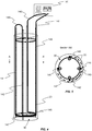
FIG.4 is a schematic diagram showing an exemplary arrangement of an optical fibre array positioned on a reinforcement assembly in a borehole; and -
FIG.5 is a cross-sectional view of the borehole along AA' inFIG. 4 . - Referring firstly to
Figure 1 , a crane or othersuitable lifting device 10 is shown lowering a reinforcement orframework assembly 20 into a borehole orcavity 30 in the ground, for the purpose of creating a subsurface concrete structure. - Once the
assembly 20 has been positioned at the desired location, concrete (not shown) is applied to fill the borehole orcavity 30, thereby surrounding theassembly 20. - As will be understood, the concrete will undergo a period of hydration, during which the concrete will harden to create a subsurface concrete structure having integral reinforcement or framework.
- The reinforcement or framework assembly 20 (hereinafter referred to as 'the assembly') is configured to define a substructure of the subsurface concrete structure to be created. As such, the
assembly 20 will typically be constructed as a cage or frame, using metal bar or the like. According to a preferred method of the invention, theassembly 20 is constructed above ground (e.g. on site or at a location remote from the intended installation location). - In exemplary embodiments, the
assembly 20 is configured for creating a concrete pile or panel of a diaphragm wall, for example. - In general terms, a fibre optic array is used to directly sense and collect temperature data during hydration of the subsurface concrete structure. That is to say, the fibre optic array functions as a temperature sensor array. This is different to known prior art monitoring systems wherein a plurality of discrete sensors are individually positioned at set subsurface locations within the poured concrete.
- In the example of
Figure 1 , a fibreoptic cable sensor 48 is provided in association with theassembly 20. The term "fibre optic cable sensor" is used to indicate a fibre optic cable in which the optical fibre acts as a sensing element. The fibreoptic cable sensor 48 is arranged in an open loop (i.e. folded/turned or doubled upon itself so as to leave an opening between its parts) having two sections (a first section and a second section) 40, 42 which are spaced apart from one another, with thefirst section 40 of the fibreoptic cable sensor 48 extending down one side of theassembly 20 and thesecond section 42 of the fibreoptic cable sensor 48 extending up from the opposing side of theassembly 20. Athird section 46 of the fibreoptic cable sensor 48 connecting the first and second sections extends across an underside of theassembly 20. The fibreoptic cable sensor 48 is attached to the assembly 20 (e.g. using an adhesive, clamps, twisted wire, clips or ties or the like), prior to location at said subsurface location. For example, the fibre optic cable sensor is attached above ground, during or after construction of theassembly 20. - In the illustrated example of
Figure 1 ,rollers 44 are used to guide the fibreoptic cable sensor 48 during the lowering of theassembly 20 into the borehole orcavity 30. It would be understood that whererollers 44 are used, the first andsecond sections optic cable sensor 48 are attached to the respective side of theassembly 20 as it is being lowered into thecavity 30. - The fibre
optic cable sensor 48 may be a conventional single mode optical fibre sensor e.g. of a kind known in the art or a multimode optical fibre sensor. - As can be seen in
Figure 2 , aninterrogator 50 is connected to eachsection optic cable sensor 48, preferably before theassembly 20 is immersed in concrete. The fibreoptic cable sensor 48 also functions as a communication link to theinterrogator 50. Theinterrogator 50 is configured to collect the measured temperature data from the first andsecond sections optic cable sensor 48 during hydration of the subsurface concrete structure. - In exemplary embodiments, the collected temperature data is used for determining one or more characteristics of the subsurface concrete structure. More particularly, the data is monitored to determine the integrity of the subsurface concrete structure, thus identifying potential anomalies within the subsurface concrete structure. For example, during hydration, a pattern of changes in the spatially distributed temperature may be anticipated along the structure, and if the collected data varies significantly from the anticipated pattern, this will indicate an anomaly within the structure (e.g. a void, fissure or non-homogeneous concentration of material). The spatially distributed temperature data can then be interrogated to identify the location of the anomaly.
- In exemplary methods of the invention, a single fibre optic cable sensor is used to collect the temperature data. In the embodiment of
Figure 2 , the first andsecond sections optic cable sensor 48 are used for detecting undesired temperature differentials across the hydrating structure (e.g. by comparing the temperature at one side with the temperature at the other side, for any given depth below ground level). In other embodiments, any number of fibre optic cable sensors could be used. - In exemplary methods of the invention, a first fibre optic cable sensor may be arranged to extend in an open loop along a central axis of the
assembly 20, and one or more additional fibre optic cable sensors may be arranged to each define a single or a plurality of open loops at peripheral locations of the assembly 20 (e.g. spaced circumferentially with respect to the periphery of the structure). - With particular reference to
Figure 3 , an exemplary method of directly sensing and collecting temperature data during hydration of the subsurface concrete structure will be described. - As mentioned above, the concrete will undergo a period of hydration, during which the concrete will harden to create a subsurface concrete structure having integral reinforcement or framework.
- At the start of the hydration period and throughout the hydration period, a
light signal 60 is transmitted down the fibreoptic cable sensor 48. - As the
light signal 60 is transmitted down the fibreoptic cable sensor 48, temperature data in the form of back-scatter signals 70 are collected by theinterrogator 50 along the length of the fibreoptic cable sensor 48. In exemplary methods, thelight signal 60 is in the form of a laser signal. - The collected back-
scatter signals 70 are reconstructed into visual form, for example in the form of a graph as shown inFigure 3 , in order to determine one or more characteristics of the subsurface concrete structure. - The temperature data is averaged over a prescribed length and sampled at a prescribed rate. For example, the temperature data may be averaged over a length of 0.5m every 0.05m along the length of the fibre
optic cable sensor 48. This provides a distributed measurement of the temperature data by the fibreoptic cable sensor 48 across the length of the hydrating concrete, rather than discrete spaced apart measurements at different positions in the hydrating concrete as currently obtained by methods known in the art. Accordingly, the risk of bypassing or not identifying a location of potential failure, as may be the case in the prior art methods if the location occurs between two discrete sensors positions, is significantly reduced. - A
region 80 with poor heat flow, which is indicative of an anomaly, will be indicated by a change in the spatially distributed temperature profile. - In exemplary embodiments, the temperature data is monitored in real time during hydration of the subsurface concrete structure. The real time monitoring of temperature data for the structure during hydration of the concrete, thereby provides a mechanism for identifying potential failures (e.g. due to the presence of voids, fissures or non-homogeneous concentrations within the structure) before the structure is completed.
- Although described with reference to concrete piles and diaphragm walls, the method is also applicable to other subsurface concrete structures, such as raft foundations etc.
- While the fibre optic cable sensor is shown in
Figure 2 as having a single open loop, it would be understood that the sensor may be arranged to define a plurality of open loops with each open loop having a downward extending section and an upward extending section. An example, of such an arrangement is shown inFigures 4 and 5 . - In the embodiment shown in
Figures 4 and 5 , the fibreoptic cable sensor 148 is arranged to define two open loops. The first loop is defined by afirst section 140 of the fibreoptic cable sensor 148 extending down one side of theassembly 20, asecond section 142 of the fibreoptic cable sensor 148 extending up from a diametrically opposite side of theassembly 20, and athird section 146 of the fibreoptic cable sensor 148 connecting the first andsecond sections third section 146 extends along an outer perimeter of the assembly (seeFigure 5 ), although it would be understood that it may extend across an underside of theassembly 20 as in the previously described embodiment. - The second loop is defined by a
fourth section 141 of the fibreoptic cable sensor 148 extending down a third side of theassembly 20, afifth section 143 of the fibreoptic cable sensor 148 extending up from a fourth side of thereinforcement assembly 20 diametrically opposite the third side, and asixth section 147 of the fibreoptic cable sensor 148 connecting the fourth andfifth sections seventh section 149 of the fibreoptic cable sensor 148 connects thesecond section 142 to thefourth section 141. - The number of loops and hence the number of sections of the fibre optic cable extending along the sides of the assembly and their relative spacing is decided by the desired spatial resolution of temperature measurement. The temporal and spatial temperature profile evaluated from the fibre optic cable sensor readings will be used for data interpretation.
- For example, for a circular cross-sectional concrete column of diameter 0.6m, and perimeter 3.77m, having four vertical fibre optic cable sections along its length would allow a peripheral spatial resolution of less than 1m.
- Although the invention has been described above with reference to one or more preferred embodiments, it will be appreciated that various changes or modifications may be made without departing from the scope of the invention as defined in the appended claims.
Claims (9)
- A method of monitoring a subsurface concrete structure, the method comprising the steps of:providing a reinforcement cage (20) or framework assembly for a subsurface concrete structure;providing a fibre optic array (48) in association with said reinforcement cage (20) or framework assembly, the fibre optic array comprising at least one fibre optic cable sensor, wherein the fibre optic cable sensor comprises a fibre optic cable which acts as a sensing element;providing an interrogator (50) connected to the fibre optic array;installing said reinforcement cage (20) or framework assembly at a desired subsurface location (30);applying concrete medium to surround the reinforcement cage or framework assembly and the at least one fibre optic cable sensor (48) at said subsurface location (30);using said at least one fibre optic cable sensor (48) immediately or shortly after the application of concrete medium to directly sense temperature data along a length of the at least one fibre optic cable sensor during hydration of the subsurface concrete structure;using said interrogator (50) to collect said temperature data during hydration of the subsurface concrete structure; andanalysing said temperature data to determine a characteristic of the subsurface concrete structure,wherein the at least one fibre optic cable sensor is folded or doubled upon itself so as to leave an opening between its parts, thereby forming an open loop arrangement having a first section (40) and a second section (42) which are spaced apart from one another and extending along a length of the reinforcement cage or framework assembly.
- A method according to claim 1, wherein the temperature data is monitored in real time during hydration of the subsurface concrete structure.
- A method according to any preceding claim, wherein the fibre optic array (48) comprises a plurality of fibre optic cable sensors (48).
- A method according to claim 3, wherein each fibre optic cable sensor (48) extends to a known depth within the reinforcement cage (20) or framework assembly of the subsurface structure.
- A method according to any preceding claim, wherein the first section (40) of said at least one fibre optic cable sensor (48) is arranged on one side of the reinforcement cage (20) or framework assembly and the second section (42) of said at least one fibre optic cable sensor (48) is arranged on an opposing side of the reinforcement cage (20) or framework assembly.
- A method according to any preceding claim, wherein a first fibre optic cable sensor (48) is arranged to extend in an open loop along a central axis of the reinforcement cage (20) or framework assembly.
- A method according to any preceding claim, wherein one or more additional fibre optic cable sensors (48) are arranged to each define a single or a plurality of open loops at a peripheral location of the reinforcement cage (20) or framework assembly.
- A method according to any preceding claim, wherein the or each fibre optic cable sensor (48) is attached to the reinforcement cage (20) or framework assembly prior to location of the reinforcement cage (20) or framework assembly at said subsurface location.
- A method according to any preceding claim, wherein the or each fibre optic cable sensor (48) is a single mode fibre optic sensor or a multimode fibre optic sensor.
Priority Applications (1)
| Application Number | Priority Date | Filing Date | Title |
|---|---|---|---|
| PL15710836T PL3102937T3 (en) | 2014-02-05 | 2015-02-05 | Method of monitoring subsurface concrete structures |
Applications Claiming Priority (3)
| Application Number | Priority Date | Filing Date | Title |
|---|---|---|---|
| GB201401921A GB201401921D0 (en) | 2014-02-05 | 2014-02-05 | Method of monitoring subsurface concrete structures |
| GBGB1403124.9A GB201403124D0 (en) | 2014-02-05 | 2014-02-21 | Method of monitoring subsurface concrete structures |
| PCT/GB2015/050321 WO2015118333A1 (en) | 2014-02-05 | 2015-02-05 | Method of monitoring subsurface concrete structures |
Publications (2)
| Publication Number | Publication Date |
|---|---|
| EP3102937A1 EP3102937A1 (en) | 2016-12-14 |
| EP3102937B1 true EP3102937B1 (en) | 2020-05-20 |
Family
ID=50344392
Family Applications (1)
| Application Number | Title | Priority Date | Filing Date |
|---|---|---|---|
| EP15710836.6A Active EP3102937B1 (en) | 2014-02-05 | 2015-02-05 | Method of monitoring subsurface concrete structures |
Country Status (9)
| Country | Link |
|---|---|
| US (1) | US10472793B2 (en) |
| EP (1) | EP3102937B1 (en) |
| DK (1) | DK3102937T3 (en) |
| ES (1) | ES2810759T3 (en) |
| GB (3) | GB201401921D0 (en) |
| HU (1) | HUE050324T2 (en) |
| PL (1) | PL3102937T3 (en) |
| PT (1) | PT3102937T (en) |
| WO (1) | WO2015118333A1 (en) |
Cited By (1)
| Publication number | Priority date | Publication date | Assignee | Title |
|---|---|---|---|---|
| EP4039885A1 (en) | 2021-02-08 | 2022-08-10 | Züblin Spezialtiefbau GmbH | Method and device for thermal monitoring of a structure of a material which sets in response to temperature change |
Families Citing this family (28)
| Publication number | Priority date | Publication date | Assignee | Title |
|---|---|---|---|---|
| CN106500868A (en) * | 2016-10-26 | 2017-03-15 | 上海市政工程设计研究总院(集团)有限公司 | Dykes and dams and the dykes and dams monitoring internal temperature system based on distribution type fiber-optic |
| AU2017416947A1 (en) * | 2017-06-01 | 2019-12-19 | Hebei Research Institute Of Construction And Geotechnical Investigation Co. Ltd. | Cast-in-place geopolymer pile with heating system |
| US10620062B2 (en) | 2017-10-23 | 2020-04-14 | Deborah D. L. Chung | Cement-based material systems and method for self-sensing and weighing |
| CN107938723A (en) * | 2017-11-14 | 2018-04-20 | 青岛理工大学 | Static pressure tubular pile extension sensor wire trend and protection device |
| CN107893420A (en) * | 2017-11-14 | 2018-04-10 | 青岛理工大学 | Static pressure pipe pile extension sensor wire trend and protection method |
| CN107843358A (en) * | 2017-12-04 | 2018-03-27 | 中国电建集团中南勘测设计研究院有限公司 | A kind of concrete abrasion early warning system and method |
| US10774493B2 (en) * | 2018-11-16 | 2020-09-15 | Horst K. Aschenbroich | Hollow rebar for post-grouting the base of reinforced concrete drilled shafts |
| US11598899B2 (en) | 2018-12-28 | 2023-03-07 | Halliburton Energy Services, Inc. | Instrumented fracturing target for data capture of simulated well |
| CN109989435B (en) * | 2019-05-22 | 2020-01-24 | 仪征市天润工程质量检测有限公司 | Bored concrete pile surpasses irritates monitoring system |
| CN110499790A (en) * | 2019-07-26 | 2019-11-26 | 国网辽宁省电力有限公司鞍山供电公司 | A kind of detection device of winter iron tower foundation construction concrete critical intensity |
| CN110485409B (en) * | 2019-08-30 | 2021-03-23 | 沙焕焕 | Composite pile construction method based on ground universe full-period actual measurement data |
| CN110725347A (en) * | 2019-10-22 | 2020-01-24 | 上海中兴思秸通讯有限公司 | Real-time detection method and system for broken pile in concrete cast-in-place pile construction process |
| RU2733098C1 (en) * | 2019-10-22 | 2020-09-29 | Георгий Яковлевич Шайдуров | System for automated monitoring of pile foundations of building structures in permafrost regions |
| US11506520B2 (en) * | 2019-10-30 | 2022-11-22 | Raytheon Company | Systems and methods for real-time, nondestructive monitoring of energetic materials |
| CN111560995B (en) * | 2020-05-28 | 2021-03-16 | 机械工业勘察设计研究院有限公司 | Device and method for testing internal force of cast-in-place pile by using optical fiber |
| CN111472395B (en) * | 2020-06-03 | 2022-02-25 | 广东财贸建设工程顾问有限公司 | Building engineering bored concrete pile defect detecting system |
| CN111608263A (en) * | 2020-06-10 | 2020-09-01 | 江苏元华光电科技有限公司 | Large-volume concrete continuous pouring digital monitoring management method and system |
| CN112627246B (en) * | 2020-12-31 | 2024-07-23 | 淮安市水利勘测设计研究院有限公司 | Underwater pile wall concrete pouring quality monitoring and testing device and method |
| JP7422692B2 (en) * | 2021-01-25 | 2024-01-26 | 大成建設株式会社 | Foundation pile damage determination system |
| CN113026829B (en) * | 2021-03-09 | 2022-05-03 | 南京大学 | Bored concrete pile integrity detection device and method based on dense distributed fiber bragg grating temperature sensing technology |
| CN113186929B (en) * | 2021-04-15 | 2022-11-04 | 山东大学 | Cast-in-place pile concrete top surface elevation control device and method |
| CN113216207B (en) * | 2021-05-14 | 2022-05-10 | 中铁一局集团(广州)建设工程有限公司 | Optical fiber monitoring device and construction method behind an underground diaphragm wall |
| CN113138033B (en) * | 2021-06-01 | 2022-03-25 | 大连理工大学 | Deep learning-based quantitative evaluation method for cavity of inner surface layer of concrete filled steel tube |
| CN113503163B (en) * | 2021-07-22 | 2025-01-10 | 苏州大学 | A method for monitoring deformation of shield-driven underground continuous wall construction |
| CN114018433A (en) * | 2021-09-17 | 2022-02-08 | 湖北三江航天红峰控制有限公司 | Testing device and testing method for temperature field in solid propellant solidified square billet |
| CN115288212B (en) * | 2022-07-05 | 2023-05-16 | 湖北工业大学 | An optical fiber implantation device and implantation method for an existing pile wall |
| CN116358732A (en) * | 2023-01-30 | 2023-06-30 | 西安热工研究院有限公司 | An array type optical fiber temperature detection component and detection method |
| CN117846045B (en) * | 2024-01-17 | 2024-07-26 | 中国科学院西北生态环境资源研究院 | Pile foundation bearing performance testing device and method |
Family Cites Families (19)
| Publication number | Priority date | Publication date | Assignee | Title |
|---|---|---|---|---|
| US5397891A (en) * | 1992-10-20 | 1995-03-14 | Mcdonnell Douglas Corporation | Sensor systems employing optical fiber gratings |
| JPH1066945A (en) * | 1996-08-29 | 1998-03-10 | Fujita Corp | Identifying the location of water leaks in underground holes |
| JP4495672B2 (en) * | 2003-07-02 | 2010-07-07 | ニューブレクス株式会社 | Structure monitoring system |
| US6886977B2 (en) * | 2003-07-17 | 2005-05-03 | General Electric Company | Measuring temperature in stationary components of electrical machines using fiber optics |
| US20070058898A1 (en) * | 2005-06-30 | 2007-03-15 | Infoscitex | Humidity sensor and method for monitoring moisture in concrete |
| US20070065071A1 (en) * | 2005-06-30 | 2007-03-22 | Infoscitex | Humidity sensor and method for monitoring moisture in concrete |
| US20070116402A1 (en) * | 2005-06-30 | 2007-05-24 | Infoscitex Corporation | Humidity sensor and method for monitoring moisture in concrete |
| EP1992926B1 (en) * | 2007-05-16 | 2015-07-29 | Hitachi Metals, Ltd. | Optical fiber vibration sensor |
| KR20100116365A (en) * | 2009-04-22 | 2010-11-01 | (주)대우건설 | Prediction technique of temperature varying for hsc column deformation by embedded fbg sensor |
| FR2953943B1 (en) * | 2010-01-11 | 2013-04-05 | Terre Armee Int | FLEXIBLE STRIP COMPRISING AT LEAST ONE OPTICAL FIBER FOR PERFORMING DEFORMATION AND / OR TEMPERATURE MEASUREMENTS |
| US8382369B2 (en) * | 2010-02-17 | 2013-02-26 | Pile Dynamics, Inc. | Pile sensing device and method of using the same |
| GB201020827D0 (en) * | 2010-12-08 | 2011-01-19 | Fotech Solutions Ltd | Distrubuted optical fibre sensor |
| PT105424A (en) * | 2010-12-10 | 2012-06-11 | Univ Aveiro | METHOD AND DEVICE FOR DETERMINING THE CURE PROCESS OF CONCRETE BASED ON OPTICAL FIBERS |
| DK2466063T3 (en) * | 2010-12-17 | 2013-11-18 | Schlumberger Technology Bv | Equipment and methods for determining the curing time in an underground well |
| BR112013018219A2 (en) * | 2011-01-20 | 2016-11-08 | Omnisens Sa | strain sensor apparatus and method for strain detection |
| US8636063B2 (en) * | 2011-02-16 | 2014-01-28 | Halliburton Energy Services, Inc. | Cement slurry monitoring |
| EP2851669A1 (en) * | 2012-06-05 | 2015-03-25 | Airbus Operations GmbH | System and method for monitoring a component of an aircraft or spacecraft in production and/or in service |
| NO347403B1 (en) * | 2013-06-13 | 2023-10-16 | Schlumberger Technology Bv | Fiber optic distributed vibration sensing with wavenumber sensitivity correction |
| US9977008B2 (en) * | 2014-03-28 | 2018-05-22 | Fugro Usa Land, Inc. | Method and apparatus for analyzing anomalies in concrete structures |
-
2014
- 2014-02-05 GB GB201401921A patent/GB201401921D0/en not_active Ceased
- 2014-02-21 GB GBGB1403124.9A patent/GB201403124D0/en not_active Ceased
-
2015
- 2015-02-05 PT PT157108366T patent/PT3102937T/en unknown
- 2015-02-05 EP EP15710836.6A patent/EP3102937B1/en active Active
- 2015-02-05 WO PCT/GB2015/050321 patent/WO2015118333A1/en not_active Ceased
- 2015-02-05 US US15/117,070 patent/US10472793B2/en active Active
- 2015-02-05 DK DK15710836.6T patent/DK3102937T3/en active
- 2015-02-05 PL PL15710836T patent/PL3102937T3/en unknown
- 2015-02-05 ES ES15710836T patent/ES2810759T3/en active Active
- 2015-02-05 HU HUE15710836A patent/HUE050324T2/en unknown
- 2015-02-05 GB GB1501947.4A patent/GB2524636B/en active Active
Non-Patent Citations (3)
| Title |
|---|
| GRAY MULLINS ET AL: "Thermal Integrity Profiling: An Innovative Technique for Drilled Shafts Special Issue: Innovation", DEEP FOUNDATIONS MAY/JUNE 2012, 2 May 2012 (2012-05-02), pages 51 - 54, XP055388918, Retrieved from the Internet <URL:http://www.grlengineers.com/wp-content/uploads/2012/05/DFI_MAY_JUN2012_pg51-54.pdf> [retrieved on 20170707] * |
| SELLOUNTOU E-A ET AL: "Thermal Integrity Profiling: A Recent Technological Advancement in Integrity Evaluation of Concrete Piles", 23 April 2013 (2013-04-23), pages 1 - 20, XP002743515, Retrieved from the Internet <URL:http://www.pile.com/reference/SeminarOnDeepFoundations2013/ThermalIntegrityProfiling.pdf> * |
| YONG WANG: "Monitoring of concrete curing process with embedded fiber Bragg gratings", PROCEEDINGS OF SPIE, vol. 4204, 1 January 2001 (2001-01-01), pages 23 - 30, XP055005138, ISSN: 0277-786X, DOI: 10.1117/12.417409 * |
Cited By (1)
| Publication number | Priority date | Publication date | Assignee | Title |
|---|---|---|---|---|
| EP4039885A1 (en) | 2021-02-08 | 2022-08-10 | Züblin Spezialtiefbau GmbH | Method and device for thermal monitoring of a structure of a material which sets in response to temperature change |
Also Published As
| Publication number | Publication date |
|---|---|
| US10472793B2 (en) | 2019-11-12 |
| US20170067222A1 (en) | 2017-03-09 |
| PT3102937T (en) | 2020-08-26 |
| GB201401921D0 (en) | 2014-03-19 |
| HUE050324T2 (en) | 2020-11-30 |
| PL3102937T3 (en) | 2021-06-14 |
| WO2015118333A1 (en) | 2015-08-13 |
| GB201501947D0 (en) | 2015-03-25 |
| GB2524636B (en) | 2016-09-14 |
| DK3102937T3 (en) | 2020-08-17 |
| GB2524636A (en) | 2015-09-30 |
| GB201403124D0 (en) | 2014-04-09 |
| ES2810759T3 (en) | 2021-03-09 |
| EP3102937A1 (en) | 2016-12-14 |
Similar Documents
| Publication | Publication Date | Title |
|---|---|---|
| US10472793B2 (en) | Method of monitoring subsurface concrete structures | |
| KR101482369B1 (en) | Pile sensing device and method of using the same | |
| KR102322975B1 (en) | Reinforcing method for slope | |
| TWI540238B (en) | Slope stabilization system | |
| BR112019024081A2 (en) | PREFABRICATED SEGMENT FOR TUNNELS AND METHOD TO PRODUCE AND MONITOR THE SAID PREFABRICATED SEGMENT | |
| KR102197696B1 (en) | Structure health monitoring system using optic fiber-based hybrid nerve network sensor, and method for the same | |
| CN105157999A (en) | Method for assessing pile integrity and lateral displacement based on distributed optical fiber sensing technology | |
| CN202869442U (en) | Side slope and landslide integrated monitoring system | |
| CN112393766A (en) | Soil state monitoring system and distributed optical fiber probe rod | |
| CN217358614U (en) | Digital steel wire for measuring temperature and humidity of cable structure in full range | |
| WO2016091972A1 (en) | Method for ascertaining characteristics of an underground formation | |
| CN110725347A (en) | Real-time detection method and system for broken pile in concrete cast-in-place pile construction process | |
| JP2021173677A (en) | Internal measurement system of concrete structure | |
| CN107543568A (en) | A kind of distributed sensing optical cable with boring distribution method and device | |
| KR102315081B1 (en) | Automatic measuring system for interconnecting with mobile | |
| CN213579481U (en) | A soil condition monitoring system and distributed optical fiber probe | |
| CN106906824A (en) | Distribution type fiber-optic prestressing force intellectual monitoring anchor cable | |
| US11118999B2 (en) | Method and investigation device for measuring stresses in an agglomerate structure | |
| Valley et al. | Monitoring mining-induced rock mass deformation using distributed strain monitoring based on fiber optics | |
| KR20110136140A (en) | Structure for measuring displacement of tunnel in tunnel and measuring method of displacement of hole using same | |
| KR100956687B1 (en) | Integrity Monitoring Method of Earth Anchor Structures Using Fiber Optic Strands | |
| CN112228155B (en) | Arrangement method and structure of multi-parameter monitoring sensors for overlying rock strata in coal mining subsidence areas | |
| CN210658298U (en) | A kind of foundation pit deformation early warning device | |
| CN211401278U (en) | Side slope monitoring device | |
| CN113738340A (en) | Real-time monitoring device and monitoring method for backfill progress of drill hole |
Legal Events
| Date | Code | Title | Description |
|---|---|---|---|
| STAA | Information on the status of an ep patent application or granted ep patent |
Free format text: STATUS: THE INTERNATIONAL PUBLICATION HAS BEEN MADE |
|
| PUAI | Public reference made under article 153(3) epc to a published international application that has entered the european phase |
Free format text: ORIGINAL CODE: 0009012 |
|
| STAA | Information on the status of an ep patent application or granted ep patent |
Free format text: STATUS: REQUEST FOR EXAMINATION WAS MADE |
|
| 17P | Request for examination filed |
Effective date: 20160805 |
|
| AK | Designated contracting states |
Kind code of ref document: A1 Designated state(s): AL AT BE BG CH CY CZ DE DK EE ES FI FR GB GR HR HU IE IS IT LI LT LU LV MC MK MT NL NO PL PT RO RS SE SI SK SM TR |
|
| AX | Request for extension of the european patent |
Extension state: BA ME |
|
| RIN1 | Information on inventor provided before grant (corrected) |
Inventor name: OUYANG, YUE Inventor name: NICHOLSON, DUNCAN Inventor name: BELL, ANDREW Inventor name: SOGA, KENICHI |
|
| DAX | Request for extension of the european patent (deleted) | ||
| STAA | Information on the status of an ep patent application or granted ep patent |
Free format text: STATUS: EXAMINATION IS IN PROGRESS |
|
| 17Q | First examination report despatched |
Effective date: 20180221 |
|
| GRAP | Despatch of communication of intention to grant a patent |
Free format text: ORIGINAL CODE: EPIDOSNIGR1 |
|
| STAA | Information on the status of an ep patent application or granted ep patent |
Free format text: STATUS: GRANT OF PATENT IS INTENDED |
|
| INTG | Intention to grant announced |
Effective date: 20190702 |
|
| GRAJ | Information related to disapproval of communication of intention to grant by the applicant or resumption of examination proceedings by the epo deleted |
Free format text: ORIGINAL CODE: EPIDOSDIGR1 |
|
| GRAJ | Information related to disapproval of communication of intention to grant by the applicant or resumption of examination proceedings by the epo deleted |
Free format text: ORIGINAL CODE: EPIDOSDIGR1 |
|
| STAA | Information on the status of an ep patent application or granted ep patent |
Free format text: STATUS: EXAMINATION IS IN PROGRESS |
|
| GRAP | Despatch of communication of intention to grant a patent |
Free format text: ORIGINAL CODE: EPIDOSNIGR1 |
|
| STAA | Information on the status of an ep patent application or granted ep patent |
Free format text: STATUS: GRANT OF PATENT IS INTENDED |
|
| INTG | Intention to grant announced |
Effective date: 20190702 |
|
| INTC | Intention to grant announced (deleted) | ||
| INTG | Intention to grant announced |
Effective date: 20191128 |
|
| GRAS | Grant fee paid |
Free format text: ORIGINAL CODE: EPIDOSNIGR3 |
|
| GRAA | (expected) grant |
Free format text: ORIGINAL CODE: 0009210 |
|
| STAA | Information on the status of an ep patent application or granted ep patent |
Free format text: STATUS: THE PATENT HAS BEEN GRANTED |
|
| RAP1 | Party data changed (applicant data changed or rights of an application transferred) |
Owner name: CAMBRIDGE ENTERPRISE LIMITED Owner name: CEMENTATION SKANSKA LIMITED Owner name: OVE ARUP & PARTNERS INTERNATIONAL LIMITED |
|
| AK | Designated contracting states |
Kind code of ref document: B1 Designated state(s): AL AT BE BG CH CY CZ DE DK EE ES FI FR GB GR HR HU IE IS IT LI LT LU LV MC MK MT NL NO PL PT RO RS SE SI SK SM TR |
|
| REG | Reference to a national code |
Ref country code: GB Ref legal event code: FG4D |
|
| REG | Reference to a national code |
Ref country code: CH Ref legal event code: EP |
|
| REG | Reference to a national code |
Ref country code: DE Ref legal event code: R096 Ref document number: 602015053009 Country of ref document: DE |
|
| REG | Reference to a national code |
Ref country code: AT Ref legal event code: REF Ref document number: 1272923 Country of ref document: AT Kind code of ref document: T Effective date: 20200615 |
|
| REG | Reference to a national code |
Ref country code: CH Ref legal event code: NV Representative=s name: VALIPAT S.A. C/O BOVARD SA NEUCHATEL, CH |
|
| REG | Reference to a national code |
Ref country code: FI Ref legal event code: FGE |
|
| REG | Reference to a national code |
Ref country code: DK Ref legal event code: T3 Effective date: 20200810 |
|
| REG | Reference to a national code |
Ref country code: NL Ref legal event code: FP |
|
| REG | Reference to a national code |
Ref country code: PT Ref legal event code: SC4A Ref document number: 3102937 Country of ref document: PT Date of ref document: 20200826 Kind code of ref document: T Free format text: AVAILABILITY OF NATIONAL TRANSLATION Effective date: 20200812 |
|
| REG | Reference to a national code |
Ref country code: NO Ref legal event code: T2 Effective date: 20200520 |
|
| REG | Reference to a national code |
Ref country code: SE Ref legal event code: TRGR |
|
| REG | Reference to a national code |
Ref country code: LT Ref legal event code: MG4D |
|
| REG | Reference to a national code |
Ref country code: EE Ref legal event code: FG4A Ref document number: E019653 Country of ref document: EE Effective date: 20200811 |
|
| PG25 | Lapsed in a contracting state [announced via postgrant information from national office to epo] |
Ref country code: IS Free format text: LAPSE BECAUSE OF FAILURE TO SUBMIT A TRANSLATION OF THE DESCRIPTION OR TO PAY THE FEE WITHIN THE PRESCRIBED TIME-LIMIT Effective date: 20200920 Ref country code: GR Free format text: LAPSE BECAUSE OF FAILURE TO SUBMIT A TRANSLATION OF THE DESCRIPTION OR TO PAY THE FEE WITHIN THE PRESCRIBED TIME-LIMIT Effective date: 20200821 Ref country code: LT Free format text: LAPSE BECAUSE OF FAILURE TO SUBMIT A TRANSLATION OF THE DESCRIPTION OR TO PAY THE FEE WITHIN THE PRESCRIBED TIME-LIMIT Effective date: 20200520 |
|
| PG25 | Lapsed in a contracting state [announced via postgrant information from national office to epo] |
Ref country code: BG Free format text: LAPSE BECAUSE OF FAILURE TO SUBMIT A TRANSLATION OF THE DESCRIPTION OR TO PAY THE FEE WITHIN THE PRESCRIBED TIME-LIMIT Effective date: 20200820 Ref country code: LV Free format text: LAPSE BECAUSE OF FAILURE TO SUBMIT A TRANSLATION OF THE DESCRIPTION OR TO PAY THE FEE WITHIN THE PRESCRIBED TIME-LIMIT Effective date: 20200520 Ref country code: HR Free format text: LAPSE BECAUSE OF FAILURE TO SUBMIT A TRANSLATION OF THE DESCRIPTION OR TO PAY THE FEE WITHIN THE PRESCRIBED TIME-LIMIT Effective date: 20200520 Ref country code: RS Free format text: LAPSE BECAUSE OF FAILURE TO SUBMIT A TRANSLATION OF THE DESCRIPTION OR TO PAY THE FEE WITHIN THE PRESCRIBED TIME-LIMIT Effective date: 20200520 |
|
| REG | Reference to a national code |
Ref country code: HU Ref legal event code: AG4A Ref document number: E050324 Country of ref document: HU |
|
| PG25 | Lapsed in a contracting state [announced via postgrant information from national office to epo] |
Ref country code: AL Free format text: LAPSE BECAUSE OF FAILURE TO SUBMIT A TRANSLATION OF THE DESCRIPTION OR TO PAY THE FEE WITHIN THE PRESCRIBED TIME-LIMIT Effective date: 20200520 |
|
| PG25 | Lapsed in a contracting state [announced via postgrant information from national office to epo] |
Ref country code: RO Free format text: LAPSE BECAUSE OF FAILURE TO SUBMIT A TRANSLATION OF THE DESCRIPTION OR TO PAY THE FEE WITHIN THE PRESCRIBED TIME-LIMIT Effective date: 20200520 Ref country code: SM Free format text: LAPSE BECAUSE OF FAILURE TO SUBMIT A TRANSLATION OF THE DESCRIPTION OR TO PAY THE FEE WITHIN THE PRESCRIBED TIME-LIMIT Effective date: 20200520 |
|
| REG | Reference to a national code |
Ref country code: DE Ref legal event code: R097 Ref document number: 602015053009 Country of ref document: DE |
|
| PG25 | Lapsed in a contracting state [announced via postgrant information from national office to epo] |
Ref country code: SK Free format text: LAPSE BECAUSE OF FAILURE TO SUBMIT A TRANSLATION OF THE DESCRIPTION OR TO PAY THE FEE WITHIN THE PRESCRIBED TIME-LIMIT Effective date: 20200520 |
|
| REG | Reference to a national code |
Ref country code: ES Ref legal event code: FG2A Ref document number: 2810759 Country of ref document: ES Kind code of ref document: T3 Effective date: 20210309 |
|
| PLBE | No opposition filed within time limit |
Free format text: ORIGINAL CODE: 0009261 |
|
| STAA | Information on the status of an ep patent application or granted ep patent |
Free format text: STATUS: NO OPPOSITION FILED WITHIN TIME LIMIT |
|
| 26N | No opposition filed |
Effective date: 20210223 |
|
| REG | Reference to a national code |
Ref country code: EE Ref legal event code: HC1A Ref document number: E019653 Country of ref document: EE |
|
| PG25 | Lapsed in a contracting state [announced via postgrant information from national office to epo] |
Ref country code: SI Free format text: LAPSE BECAUSE OF FAILURE TO SUBMIT A TRANSLATION OF THE DESCRIPTION OR TO PAY THE FEE WITHIN THE PRESCRIBED TIME-LIMIT Effective date: 20200520 |
|
| PG25 | Lapsed in a contracting state [announced via postgrant information from national office to epo] |
Ref country code: MC Free format text: LAPSE BECAUSE OF FAILURE TO SUBMIT A TRANSLATION OF THE DESCRIPTION OR TO PAY THE FEE WITHIN THE PRESCRIBED TIME-LIMIT Effective date: 20200520 |
|
| REG | Reference to a national code |
Ref country code: AT Ref legal event code: UEP Ref document number: 1272923 Country of ref document: AT Kind code of ref document: T Effective date: 20200520 |
|
| PG25 | Lapsed in a contracting state [announced via postgrant information from national office to epo] |
Ref country code: CY Free format text: LAPSE BECAUSE OF FAILURE TO SUBMIT A TRANSLATION OF THE DESCRIPTION OR TO PAY THE FEE WITHIN THE PRESCRIBED TIME-LIMIT Effective date: 20200520 |
|
| PG25 | Lapsed in a contracting state [announced via postgrant information from national office to epo] |
Ref country code: MK Free format text: LAPSE BECAUSE OF FAILURE TO SUBMIT A TRANSLATION OF THE DESCRIPTION OR TO PAY THE FEE WITHIN THE PRESCRIBED TIME-LIMIT Effective date: 20200520 |
|
| PG25 | Lapsed in a contracting state [announced via postgrant information from national office to epo] |
Ref country code: MT Free format text: LAPSE BECAUSE OF FAILURE TO SUBMIT A TRANSLATION OF THE DESCRIPTION OR TO PAY THE FEE WITHIN THE PRESCRIBED TIME-LIMIT Effective date: 20200520 |
|
| REG | Reference to a national code |
Ref country code: CH Ref legal event code: U11 Free format text: ST27 STATUS EVENT CODE: U-0-0-U10-U11 (AS PROVIDED BY THE NATIONAL OFFICE) Effective date: 20260303 |
|
| PGFP | Annual fee paid to national office [announced via postgrant information from national office to epo] |
Ref country code: LU Payment date: 20260227 Year of fee payment: 12 Ref country code: NL Payment date: 20260227 Year of fee payment: 12 |
|
| PGFP | Annual fee paid to national office [announced via postgrant information from national office to epo] |
Ref country code: HU Payment date: 20260220 Year of fee payment: 12 |
|
| PGFP | Annual fee paid to national office [announced via postgrant information from national office to epo] |
Ref country code: SE Payment date: 20260227 Year of fee payment: 12 |
|
| PGFP | Annual fee paid to national office [announced via postgrant information from national office to epo] |
Ref country code: GB Payment date: 20260227 Year of fee payment: 12 |
|
| PGFP | Annual fee paid to national office [announced via postgrant information from national office to epo] |
Ref country code: ES Payment date: 20260302 Year of fee payment: 12 |
|
| PGFP | Annual fee paid to national office [announced via postgrant information from national office to epo] |
Ref country code: DE Payment date: 20260227 Year of fee payment: 12 Ref country code: NO Payment date: 20260303 Year of fee payment: 12 Ref country code: DK Payment date: 20260227 Year of fee payment: 12 Ref country code: IE Payment date: 20260227 Year of fee payment: 12 |
|
| PGFP | Annual fee paid to national office [announced via postgrant information from national office to epo] |
Ref country code: AT Payment date: 20260302 Year of fee payment: 12 |
|
| PGFP | Annual fee paid to national office [announced via postgrant information from national office to epo] |
Ref country code: FI Payment date: 20260226 Year of fee payment: 12 Ref country code: BE Payment date: 20260227 Year of fee payment: 12 Ref country code: IT Payment date: 20260227 Year of fee payment: 12 |
|
| PGFP | Annual fee paid to national office [announced via postgrant information from national office to epo] |
Ref country code: FR Payment date: 20260227 Year of fee payment: 12 |
|
| PGFP | Annual fee paid to national office [announced via postgrant information from national office to epo] |
Ref country code: TR Payment date: 20260205 Year of fee payment: 12 |
|
| PGFP | Annual fee paid to national office [announced via postgrant information from national office to epo] |
Ref country code: CH Payment date: 20260303 Year of fee payment: 12 Ref country code: PT Payment date: 20260205 Year of fee payment: 12 Ref country code: CZ Payment date: 20260212 Year of fee payment: 12 |
|
| PGFP | Annual fee paid to national office [announced via postgrant information from national office to epo] |
Ref country code: PL Payment date: 20260205 Year of fee payment: 12 |
|
| PGFP | Annual fee paid to national office [announced via postgrant information from national office to epo] |
Ref country code: EE Payment date: 20260227 Year of fee payment: 12 |