EP3102908B1 - Structured light matching of a set of curves from two cameras - Google Patents
Structured light matching of a set of curves from two cameras Download PDFInfo
- Publication number
- EP3102908B1 EP3102908B1 EP15746050.2A EP15746050A EP3102908B1 EP 3102908 B1 EP3102908 B1 EP 3102908B1 EP 15746050 A EP15746050 A EP 15746050A EP 3102908 B1 EP3102908 B1 EP 3102908B1
- Authority
- EP
- European Patent Office
- Prior art keywords
- images
- scene
- light
- epipolar
- plausible
- Prior art date
- Legal status (The legal status is an assumption and is not a legal conclusion. Google has not performed a legal analysis and makes no representation as to the accuracy of the status listed.)
- Active
Links
Images


Classifications
-
- H—ELECTRICITY
- H04—ELECTRIC COMMUNICATION TECHNIQUE
- H04N—PICTORIAL COMMUNICATION, e.g. TELEVISION
- H04N13/00—Stereoscopic video systems; Multi-view video systems; Details thereof
- H04N13/20—Image signal generators
- H04N13/204—Image signal generators using stereoscopic image cameras
- H04N13/246—Calibration of cameras
-
- G—PHYSICS
- G01—MEASURING; TESTING
- G01B—MEASURING LENGTH, THICKNESS OR SIMILAR LINEAR DIMENSIONS; MEASURING ANGLES; MEASURING AREAS; MEASURING IRREGULARITIES OF SURFACES OR CONTOURS
- G01B11/00—Measuring arrangements characterised by the use of optical techniques
- G01B11/24—Measuring arrangements characterised by the use of optical techniques for measuring contours or curvatures
- G01B11/25—Measuring arrangements characterised by the use of optical techniques for measuring contours or curvatures by projecting a pattern, e.g. one or more lines, moiré fringes on the object
-
- G—PHYSICS
- G06—COMPUTING; CALCULATING OR COUNTING
- G06T—IMAGE DATA PROCESSING OR GENERATION, IN GENERAL
- G06T7/00—Image analysis
- G06T7/50—Depth or shape recovery
- G06T7/521—Depth or shape recovery from laser ranging, e.g. using interferometry; from the projection of structured light
-
- G—PHYSICS
- G06—COMPUTING; CALCULATING OR COUNTING
- G06T—IMAGE DATA PROCESSING OR GENERATION, IN GENERAL
- G06T7/00—Image analysis
- G06T7/50—Depth or shape recovery
- G06T7/55—Depth or shape recovery from multiple images
- G06T7/593—Depth or shape recovery from multiple images from stereo images
-
- H—ELECTRICITY
- H04—ELECTRIC COMMUNICATION TECHNIQUE
- H04N—PICTORIAL COMMUNICATION, e.g. TELEVISION
- H04N13/00—Stereoscopic video systems; Multi-view video systems; Details thereof
- H04N13/20—Image signal generators
- H04N13/204—Image signal generators using stereoscopic image cameras
- H04N13/239—Image signal generators using stereoscopic image cameras using two 2D image sensors having a relative position equal to or related to the interocular distance
-
- G—PHYSICS
- G06—COMPUTING; CALCULATING OR COUNTING
- G06T—IMAGE DATA PROCESSING OR GENERATION, IN GENERAL
- G06T2207/00—Indexing scheme for image analysis or image enhancement
- G06T2207/10—Image acquisition modality
- G06T2207/10016—Video; Image sequence
- G06T2207/10021—Stereoscopic video; Stereoscopic image sequence
-
- G—PHYSICS
- G06—COMPUTING; CALCULATING OR COUNTING
- G06T—IMAGE DATA PROCESSING OR GENERATION, IN GENERAL
- G06T2207/00—Indexing scheme for image analysis or image enhancement
- G06T2207/10—Image acquisition modality
- G06T2207/10028—Range image; Depth image; 3D point clouds
-
- G—PHYSICS
- G06—COMPUTING; CALCULATING OR COUNTING
- G06T—IMAGE DATA PROCESSING OR GENERATION, IN GENERAL
- G06T2207/00—Indexing scheme for image analysis or image enhancement
- G06T2207/10—Image acquisition modality
- G06T2207/10141—Special mode during image acquisition
- G06T2207/10152—Varying illumination
-
- G—PHYSICS
- G06—COMPUTING; CALCULATING OR COUNTING
- G06T—IMAGE DATA PROCESSING OR GENERATION, IN GENERAL
- G06T2207/00—Indexing scheme for image analysis or image enhancement
- G06T2207/20—Special algorithmic details
- G06T2207/20068—Projection on vertical or horizontal image axis
-
- G—PHYSICS
- G06—COMPUTING; CALCULATING OR COUNTING
- G06T—IMAGE DATA PROCESSING OR GENERATION, IN GENERAL
- G06T2207/00—Indexing scheme for image analysis or image enhancement
- G06T2207/30—Subject of image; Context of image processing
- G06T2207/30204—Marker
-
- G—PHYSICS
- G06—COMPUTING; CALCULATING OR COUNTING
- G06T—IMAGE DATA PROCESSING OR GENERATION, IN GENERAL
- G06T2207/00—Indexing scheme for image analysis or image enhancement
- G06T2207/30—Subject of image; Context of image processing
- G06T2207/30244—Camera pose
Definitions
- the present invention generally relates to the field of three-dimensional scanning of the surface geometry of an object, and, more particularly, to structured light stereovision.
- Three-dimensional scanning and digitization of the surface geometry of objects is commonly used in many industries and services, and their applications are numerous. A few examples of such applications are inspection and measurement of shape conformity in industrial production systems, reverse engineering of existing parts with complex geometry, biometry, etc.
- the shape of an object is scanned and digitized using a ranging sensor that measures the distance between the sensor and a set of points on the surface.
- a ranging sensor that measures the distance between the sensor and a set of points on the surface.
- range sensors Different principles have been developed for range sensors. Among them, triangulation-based range sensors are generally adequate for close range measurements, such as distances inferior to a few meters.
- triangulation-based range sensors are generally adequate for close range measurements, such as distances inferior to a few meters.
- at least two rays that converge to the same feature point on the object are obtained from two different viewpoints separated by a baseline distance. From the baseline and two ray directions, the relative position of the observed point can be recovered. The intersection of both rays is determined using the knowledge of one side length and two angles in the triangle, which actually is the principle of triangulation in stereovision.
- the challenge in stereovision is to efficiently identify which pixels correspond to each other in each image of the stereo pair composing a frame. This problem is especially important for portable or hand held scanners where, in the most general case, it is imposed that all necessary information for matching is to be found within a single frame.
- one of the light detectors with a light projector that outputs a set of rays in known directions.
- a light projector that outputs a set of rays in known directions.
- the light source can be a coherent source (laser) or non coherent source (e.g. white light) projecting a spot, a light plane or many other possible patterns.
- coherent source laser
- non coherent source e.g. white light
- the use of a light projector facilitates the detection of reflected points everywhere on the object surface, the more complex the pattern will be, the greater the challenge will be to efficiently identify corresponding pixels and rays.
- Projecting thin monochromatic stripes is advantageous for obtaining good signal-to-noise ratio and simplifying image processing to obtain 3D points from each single frame. Having a single stripe observable by each camera insures that each epipolar line intersects the stripe once thus avoiding matching ambiguities.
- One approach that was proposed consists in projecting a grid of stripes. Projecting a grid is further interesting for surface reconstruction since the projected pattern produces a network of curves on the object surface where tangent curves from two directions make it possible to measure the surface normal. Surface normal information can be advantageously exploited in real-time surface reconstruction from 3D measurements as described in US Pat. No. 7,487,063 . Increasing the number of stripes is advantageous for scanning speed but as the number of stripes is increased, the complexity of matching image points before applying triangulation grows exponentially and introduces ambiguities that, in some cases, cannot be resolved.
- a computer-implemented method performed by at least one computer processor for matching points between two images of a scene, the method including:
- the invention extends to a system for matching points between two images of a scene, including:
- the invention further extends to computer program product comprising a computer readable memory storing computer executable instructions thereon that when executed by at least one computer processor perform the method of the invention.
- the senor has two cameras and a light projector unit, the projected pattern being provided by the light projector unit projecting at least one sheet of light onto the scene, the cameras and the light projector unit being calibrated in a common coordinate system.
- the method further comprises validating the matching points to discard the matching points if the figure of merit fails to meet a quality of match threshold.
- the method further comprises repeating the computer-implemented method for a plurality of frames.
- the method further comprises calculating sets of 3D points using the matching points in the frame.
- the method further comprises estimating a position of the sensor at each frame to integrate the 3D points in a common coordinate system, wherein the estimating the position of the sensor includes using at least one of targets affixed to the scene, a geometry of the scene and a texture of the scene.
- the method further comprises exploiting the images for the calculating the sets of 3D points to obtain segments of 3D curves.
- the light projector unit includes two light projectors each projecting at least one sheet of light onto the scene, the projected pattern being provided by a single one of the two light projectors at each frame and the projected pattern differing for each of the two light projectors.
- the at least one sheet of light is a plane of light.
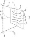
- FIG. 1 illustrates an example embodiment of the sensor 100.
- One or more light projector units 130 are mounted between the two cameras 110. Each camera 110 has a field of view 120. Each light projector unit 130 projects a pattern within a respective span 140, labelled 140a and 140b.
- the light projector unit 130 includes a single light projector.
- the sensor 102 has a different embodiment for the light projector unit which includes two light projectors 130a, 130b.
- the light projectors could be laser light projectors, white light projectors etc.
- the baseline 150 between the cameras 110 is 170 mm and the focal length of the lens of the cameras is 5,7 mm.
- the vergence of the optical axes of the two cameras is about 30°.
- the number of light planes is 5 but can vary, for example between 1 and 15 or even more.
- the two light projectors 130a, 130b are oriented so as to produce different patterns creating intersecting curves 300 on the surface as shown in FIG. 3 .
- the system will alternately project each pattern.
- Two sets of curves 310 and 320 are projected by projectors 130a, 130b respectively. They are labelled 310a, 310b, 310c, 310d and 310e and 320a, 320b, 320c, 320d and 320e.
- the light projectors 130a and 130b are themselves oriented at an angle to the object, for example +30° and -30°, to produce the different patterns.
- a projection unit 130 could include a programmable light projector unit which could project more than one pattern of light.
- a projection unit 130 could be programmed to project the two sets of intersecting curves 300 and an additional light plane simultaneously or alternatively.
- the cameras 110 and the light projector unit 130 are calibrated in a common coordinate system. This means that intrinsic parameters, including distortion parameters, as well as extrinsic parameters for both cameras 110 are measured.
- Each of the sheets of light that are projected, are calibrated in the same coordinate system. In this example, the sheets of light are planar approximations. It is also possible to affix bandpass filters on the camera lenses to match the wavelength of the projector. This will reduce interferences from ambient light and other sources.
- 3D points can be obtained after applying the following computer-implemented method.
- Two images of a frame are captured using two cameras 110.
- the two images are captured simultaneously, meaning that there is no relative displacement between the scene and the sensor 100 during the acquisition of the images or that this relative displacement is negligible.
- the cameras are synchronized to either capture the images at the same time or sequentially during an extended period of time in which the relative position of the sensor 100 with respect to the scene remains the same or varies within a predetermined negligible range. Both of these cases are considered to be a simultaneous capture of the images by the sensor.
- the two images of a frame contain the reflection of the projected pattern in the scene, from the two respective viewpoints of the cameras 110.
- the reflected pattern appears as a set of curve sections in each image. These curve sections appear lighter than the background in the images and can be segmented using state of the art techniques.
- One technique consists in thresholding the image signal. Segmentation validation can be applied since the profile of a curve is typical; it appears in an image as a crest profile. The width can also be validated. To reduce an impact of noise, the length of a curve segment will also exceed a minimum threshold that is set to a predetermined number of pixels, such as 2 pixels, for example.
- the pixels that are part of the same connected component define a blob that is indexed with a label. The position of the center of the profile section is finally estimated for each pixel line along the blob before joining these centers to compose a polyline.
- an epipolar plane is selected.
- An example epipolar plane 430 is shown in FIG. 4 which is an illustration 400 of an epipolar plane 430 overlaid on a scene 420.
- the epipolar planes share a common line segment between the center of projection 450 and 460 of the two cameras C1 and C2.
- the line segment C1-C2 acts as a rotational axis for defining the epipolar planes.
- the set of epipolar planes can be indexed using a parameter angle or, equivalently, a pixel coordinate in an image.
- An epipolar plane intersects the two image planes and thus defines two conjugate epipolar lines.
- each image line is an index of an epipolar plane.
- the scene 420 is planar.
- a ray 440 arising from the center of projection 470 of Projector P is shown in dotted line.
- the curve profiles 410 reflected from the scene 420 are apparent. They are labelled 410a, 410b, 410c, 410d and 410e.
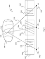
- FIG. 5 depicts a view 500 of the images, a projected pattern and its reflection on an object.
- the first camera C1 is represented by its center of projection 552 and its image plane 540.
- the second camera C2 is represented by its center of projection 554 and its image plane 542.
- the projector P is illustrated by a center of projection 470 and an image plane 536. It is not necessary that the center of projection 470 of the projector be located on the baseline between the centers of projection 552, 554 of the cameras although it is the case in the example embodiment of Fig. 5 .
- the intersection 550 between the image planes and the epipolar plane is shown using a dotted line. Rays 522, 520 and 524 belong to the same epipolar plane.
- the projector projects a light plane 532 onto the object 544, thus producing a reflected curve 510.
- This reflected curve 510 is then imaged in the first image captured by the first camera C1 (imaged curve 530) while it is also imaged in the second image captured by the second camera C2 (imaged curve 534).
- Point 546 on reflected curve 510 is then present on imaged curves 530, 534 and should be properly identified and matched in these images to allow finding its 3D coordinates.
- the imaged curves 530, 534 intersect the illustrated epipolar plane on intersection 550 along rays 522 and 520, originating from the reflected curve 510 on the object 544.
- FIG. 6 is a representation 600 of ray crossings from the two cameras and the projector.
- Rays 604 and 606 are captured by cameras C2 and C1 respectively. Ray 602 is projected by the projector P. For the projector P, the rays can be indexed using an angle 630. Some intersections 610 are a more probable match, such as intersection 610b which appears to cross in a single point while other intersections, such as intersections 610a and 610c have a greater error.
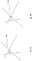
- FIGS. 7A and 7B illustrate two example error measurements that can be attributed to an intersection.
- the error measure 700 is the minimal sum of distances between a point and each of the three rays.
- the error measure 702 is the distance between the intersection of the two camera rays and the projector ray.
- the number of plausible combinations can be reduced significantly after imposing a threshold to the obtained values.
- the second error measure can be computed efficiently while allowing one to keep only the closest plane. This will reduce the matching complexity to O(N 2 ).
- a graph 800 of the errors with respect to the epipolar index is depicted for each of four triplets with curves 802, 804, 806 and 808.
- Graph 800 combines the information for all plausible triplets. More importantly it integrates, for a given triplet, all the information for a blob along the epipolar planes. Thus, for example, after calculating the average error for a given curve, one will obtain a figure of merit for matching the corresponding triplet. In FIG. 8 , the triplet whose error is depicted at curve 806 would produce the best figure of merit in this example.
- the average error can be further validated after applying a threshold.
- 3D points are calculated from the observations for each triplet. For that purpose, one may minimise the distance between the 3D point and each of the three rays in space. It is then assumed that the projected light sheets are very well calibrated, either parametrically or using a look-up table (LUT) to eventually obtain more accurate measurements. In practical applications, the projected light sheet produced through commercial optic components may not correspond exactly to a plane. For this reason, the use of a LUT may be more appropriate. Another possible approach consists in only exploiting the images from the two cameras for the final calculation of the 3D points. One may otherwise minimise the reprojection error of a 3D point, in the 2D images. It is then not necessary to accurately calibrate the projected planes.
- LUT look-up table
- the 3D measurement is less affected by the profile of the reflected signal such as a texture discontinuity on the surface of the object.
- the resulting 3D points are more accurate. After calculating the sets of 3D points, one obtains segments of 3D curves.
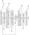
- Example steps for the matching method 900 are shown in FIG. 9 .
- Blobs are extracted 910 in both images.
- An epipolar plane is selected 920. All plausible triplet combinations along the selected epipolar plane are identified 930.
- a figure of merit is calculated 940 for each of the triplet combinations.
- each image blob is associated 950 with the most plausible triplet.
- Each match is validated 960.
- the sets of 3D points are then calculated 970.
- the method benefits from the spatial continuity of the blobs that are matched over several epipolar planes as opposed to independent matching along each of the epipolar planes. Nevertheless, it is still possible that some matching errors remain. For instance, a blob may appear as a "Y" shape structure in one image, due to the incidental projection of two curves on a specific geometry. Furthermore, if the number of planes increases, for instance beyond 15, the number of ambiguities may also increase. However, those ambiguities would have to stay persistent from one frame to the other to affect the surface when a surface reconstruction method such as that described in US Pat. No. 7,487,063 takes the 3D points as input. Actually, this type of approach is well adapted for eliminating outlier observations since the surface is reconstructed in areas where multiple observations have been acquired.
- the system When integrated in a mobile 3D sensor system, that is when there is relative motion between the object and the sensor, the system estimates its position at each frame in order to integrate 3D points in a common coordinate system.
- the system may estimate the position of the sensor at each frame using targets, such as retro-reflective targets, for example, or using the geometry or texture of the object when the object is rigid (or "quasi-rigid").
- targets such as retro-reflective targets, for example, or using the geometry or texture of the object when the object is rigid (or "quasi-rigid").
- the pose of the sensor may also be calculated after matching texture characteristics.
- two such sets of light sheets produce two sets of curves 310 and 320, in this case parallel lines, when projected on a plane.
- the system then projects alternating sets of light sheets with different orientations.
- the 3D curve sections that would be captured on the surface of an object make it possible to estimate local tangent vectors on the surface of the observed object.
- local tangent vectors can be calculated along different directions and from these 3D tangent vectors, one will calculate the surface normal orientation on the surface. Surface normal information can help improve 3D surface reconstruction.
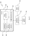
- FIG. 10 is a block diagram showing example main components of the system 980.
- the sensor 982 includes a first camera 984 and at least a second camera 986 as well as a light projector unit 988 including at least one light projector.
- a frame generator 990 may be used to assemble the images captured by the cameras in a single frame.
- the sensor 982 is in communications with at least one computer processor 992 for implementing the processing steps to match points between the images of the frame.
- the computer processor(s) 992 is in electronic communications with an output device 994 to output the matched points and/or any additional or intermediary outputs.
- Input device(s) 996 can therefore be provided for this purpose.
- the method described herein is carried out with two images thereby forming triplet combinations, more than two images could be acquired per frame and the combinations could contain more than three elements. Alternatively or additionally, if more than two images are acquired per frame, the triplet combinations for two of these images could be used to match the points and the additional image(s) could be used to validate the match.
- the techniques described above may be implemented, for example, in hardware, software tangibly stored on a computer-readable medium, firmware, or any combination thereof.
- the techniques described above may be implemented in one or more computer programs executing on a programmable computer including a processor, a storage medium readable by the processor (including, for example, volatile and non-volatile memory and/or storage elements), at least one input device, and at least one output device.
- Program code may be applied to input entered using the input device to perform the functions described and to generate output.
- the output may be provided to one or more output devices.
- Each computer program within the scope of the claims below may be implemented in any programming language, such as assembly language, machine language, a high-level procedural programming language, or an object-oriented programming language.
- the programming language may, for example, be a compiled or interpreted programming language.
- Each such computer program may be implemented in a computer program product tangibly embodied in a machine-readable storage device for execution by a computer processor.
- Method steps of the invention may be performed by a computer processor executing a program tangibly embodied on a computer-readable medium to perform functions of the invention by operating on input and generating output.
- Suitable processors include, for example, both general and special purpose microprocessors.
- the processor receives instructions and data from a read-only memory and/or a random access memory.
- Storage devices suitable for tangibly embodying computer program instructions include, for example, all forms of non-volatile memory, such as semiconductor memory devices, including EPROM, EEPROM, and flash memory devices; magnetic disks such as internal hard disks and removable disks; magneto-optical disks; and CD-ROMs. Any of the foregoing may be supplemented by, or incorporated in, specially-designed ASICs (application-specific integrated circuits) or FPGAs (Field-Programmable Gate Arrays).
- a computer can generally also receive programs and data from a storage medium such as an internal disk (not shown) or a removable disk.
Description
- The present invention generally relates to the field of three-dimensional scanning of the surface geometry of an object, and, more particularly, to structured light stereovision.
- Three-dimensional scanning and digitization of the surface geometry of objects is commonly used in many industries and services, and their applications are numerous. A few examples of such applications are inspection and measurement of shape conformity in industrial production systems, reverse engineering of existing parts with complex geometry, biometry, etc.
- The shape of an object is scanned and digitized using a ranging sensor that measures the distance between the sensor and a set of points on the surface. Different principles have been developed for range sensors. Among them, triangulation-based range sensors are generally adequate for close range measurements, such as distances inferior to a few meters. Using this type of apparatus, at least two rays that converge to the same feature point on the object are obtained from two different viewpoints separated by a baseline distance. From the baseline and two ray directions, the relative position of the observed point can be recovered. The intersection of both rays is determined using the knowledge of one side length and two angles in the triangle, which actually is the principle of triangulation in stereovision. The challenge in stereovision is to efficiently identify which pixels correspond to each other in each image of the stereo pair composing a frame. This problem is especially important for portable or hand held scanners where, in the most general case, it is imposed that all necessary information for matching is to be found within a single frame.
- To simplify the matching problem, one can replace one of the light detectors with a light projector that outputs a set of rays in known directions. In this case, it is possible to exploit the orientation of the projected rays and each detected ray reflected on the object surface to find the matching point. It is then possible to calculate the coordinates of each observed feature point relative to the basis of the triangle.
- Although specialized light detectors can be used, digital CCD or CMOS cameras are typically used.
- For the projector, the light source can be a coherent source (laser) or non coherent source (e.g. white light) projecting a spot, a light plane or many other possible patterns. Although the use of a light projector facilitates the detection of reflected points everywhere on the object surface, the more complex the pattern will be, the greater the challenge will be to efficiently identify corresponding pixels and rays.
- For this reason, one will further exploit properties from the theory of projective geometry. It has been well known in the field for at least 30 years in the case of two views that one may exploit epipolar constraints to limit the search of corresponding pixels to a single straight line, as opposed to the search in the entire image. This principle is widely exploited both in passive and active (with a projector) stereovision. One example of this usage is described in
US Pat. No. 8,032,327 wherein a laser projector projects two perpendicular light planes as a crosshair pattern whose reflection on the surface is captured by two cameras.WO 2010/015086 also discloses obtaining a three-dimensional surface geometric characteristic using a crosshair pattern. Projecting thin monochromatic stripes is advantageous for obtaining good signal-to-noise ratio and simplifying image processing to obtain 3D points from each single frame. Having a single stripe observable by each camera insures that each epipolar line intersects the stripe once thus avoiding matching ambiguities. - To reduce the time that is necessary to capture the shape of the surface of an object, one will need either to increase the frame rate or increase the number of stripes that are projected simultaneously, or both. One approach that was proposed consists in projecting a grid of stripes. Projecting a grid is further interesting for surface reconstruction since the projected pattern produces a network of curves on the object surface where tangent curves from two directions make it possible to measure the surface normal. Surface normal information can be advantageously exploited in real-time surface reconstruction from 3D measurements as described in
US Pat. No. 7,487,063 . Increasing the number of stripes is advantageous for scanning speed but as the number of stripes is increased, the complexity of matching image points before applying triangulation grows exponentially and introduces ambiguities that, in some cases, cannot be resolved. - One way to solve ambiguities consists in adding one or more cameras but the hardware complexity increases and that will reduce the frame rate limit for a given bandwidth. Methods exploiting one or two cameras have been proposed to match points from a projected grid. The intersection of the reflected curves makes it possible to segment and identify connected networks of curve sections to set additional matching constraints. However, points that are extracted near the intersection of two curves are less precise. "Near" means within a distance where image processing operators on pixels from the two curves, interfere. To maintain precision, one will need to discard and thus lose these points.
- It would be helpful to alternately produce two sets of non crossing curves to benefit from the surface normal orientation extracted from the surface tangents while avoiding the projection of a grid in a single frame. However, the matching challenge would remain. One solution would consist in projecting multicolored stripes. However, the color reflectivity on some materials would harm the quality of matching and the projector would need to be more complex. Another approach imposes to position an object on a planar background that must be visible in each frame. This clearly limits the flexibility of the system, especially when it is required to measure objects on site without interfering with the environment.
- A need remains for a solution which solves the matching problem independently for each single frame, with only two cameras, a projected pattern which may change and no particular constraint on the observed scene.
- According to the invention there is provided a computer-implemented method performed by at least one computer processor for matching points between two images of a scene, the method including:
- retrieving two images acquired by a sensor, said two images forming a frame captured at a single relative position between the scene and the sensor, said images each containing a reflection of a projected pattern on said scene;
- extracting blobs from said reflection in said images and individually labelling said blobs with a unique identifier;
- selecting a selected epipolar plane from a set of epipolar planes and defining a conjugate epipolar line on each of said images;
- identifying plausible combinations, said plausible combinations including a light sheet label of said projected pattern and the respective unique identifier for two plausible blobs where each plausible blob is selected from said blobs in each of said images respectively, said plausible blobs crossing the conjugate epipolar line of the respective image;
- calculating a matching error for each of the plausible combinations;
- repeating said steps of selecting, identifying and calculating for each epipolar plane of said set of epipolar planes;
- determining a most probable combination by computing a figure of merit for said plausible combinations using said matching error for each epipolar plane of said set of epipolar planes;
- identifying matching points in said frame from said most probable combination; generating an output identifying said matching points in said frame.
- The invention extends to a system for matching points between two images of a scene, including:
- a sensor including
- a light projector unit projecting sheets of light onto said scene thereby providing a projected pattern on said scene; and
- two cameras for acquiring said two images of said scene, said two images forming a frame captured at a single relative position between the scene and the sensor, said images each containing a reflection of said projected pattern on said scene;
- wherein the cameras and the light projector unit are calibrated in a common coordinate system; and
- at least one computer processor in electronic communications with said sensor for
retrieving said two images acquired by said cameras;- extracting blobs from said reflection in said images and individually labelling said blobs with a unique identifier;
- selecting a selected epipolar plane from a set of epipolar planes and defining a conjugate epipolar line on each of said images;
- identifying plausible combinations, said plausible combinations including a light sheet label of said projected pattern and the respective unique identifier for two plausible blobs where each plausible blob is selected from said blobs in each of said images respectively, said plausible blobs crossing the conjugate epipolar line of the respective image;
- calculating a matching error for each of the plausible combinations;
- repeating said steps of selecting, identifying and calculating for each epipolar plane of said set of epipolar planes;
- determining a most probable combination by computing a figure of merit for said plausible combinations using said matching error for each epipolar plane of said set of epipolar planes; and
- identifying matching points in said frame from said most probable combination;
- at least one computer output in electronic communications with said processor for
generating an output identifying said matching points in said frame. - The invention further extends to computer program product comprising a computer readable memory storing computer executable instructions thereon that when executed by at least one computer processor perform the method of the invention.
- In one embodiment, the sensor has two cameras and a light projector unit, the projected pattern being provided by the light projector unit projecting at least one sheet of light onto the scene, the cameras and the light projector unit being calibrated in a common coordinate system.
- In one embodiment, the method further comprises validating the matching points to discard the matching points if the figure of merit fails to meet a quality of match threshold.
- In one embodiment, the method further comprises repeating the computer-implemented method for a plurality of frames.
- In one embodiment, the method further comprises calculating sets of 3D points using the matching points in the frame.
- In one embodiment, the method further comprises estimating a position of the sensor at each frame to integrate the 3D points in a common coordinate system, wherein the estimating the position of the sensor includes using at least one of targets affixed to the scene, a geometry of the scene and a texture of the scene.
- In one embodiment, the method further comprises exploiting the images for the calculating the sets of 3D points to obtain segments of 3D curves.
- In one embodiment, the light projector unit includes two light projectors each projecting at least one sheet of light onto the scene, the projected pattern being provided by a single one of the two light projectors at each frame and the projected pattern differing for each of the two light projectors.
- In one embodiment, the at least one sheet of light is a plane of light.
- The above-mentioned features and objects of the present disclosure will become more apparent with reference to the following description taken in conjunction with the accompanying drawings, wherein like reference numerals denote like elements and in which:
-
FIG. 1 includesFIG. 1A andFIG. 1B , whereinFIG. 1A is an illustration of an example system configuration with a light projector unit andFIG. 1B is an illustration of an example system configuration with a light projector unit which includes two light projectors; -
FIG. 2 is an illustration of a light projector unit projecting a set of light planes; -
FIG. 3 is an illustration of two combined patterns reflected from a planar surface; -
FIG. 4 is a representation of an epipolar plane overlaid on a scene; -
FIG. 5 depicts a view of the images, a projected pattern and its reflection on an object; -
FIG. 6 is a representation of ray crossings from the two cameras and light projector unit; -
FIG. 7 includesFIG. 7A and FIG. 7B , whereinFIG. 7A depicts one way of measuring the quality of a match,FIG. 7B depicts another way of measuring the quality of a match; -
FIG. 8 depicts a graph of the matching error for a set of blobs; -
FIG. 9 is a flowchart of an example method for matching and producing 3D points; -
FIG. 10 is a block diagram of example main components of the system for matching and producing 3D points. - In order to efficiently find matches in every frame using two cameras, a system and computer-implemented method are proposed.
-
FIG. 1 illustrates an example embodiment of thesensor 100. One or morelight projector units 130 are mounted between the twocameras 110. Eachcamera 110 has a field ofview 120. Eachlight projector unit 130 projects a pattern within arespective span 140, labelled 140a and 140b. InFIG. 1A , thelight projector unit 130 includes a single light projector. InFIG. 1B , thesensor 102 has a different embodiment for the light projector unit which includes twolight projectors - In one example embodiment, the
baseline 150 between thecameras 110 is 170 mm and the focal length of the lens of the cameras is 5,7 mm. The vergence of the optical axes of the two cameras is about 30°. For thelight projector unit 130 shown inFIG. 2 , the number of light planes is 5 but can vary, for example between 1 and 15 or even more. Anexample embodiment 200 of alight projector unit 130 that produces 5light planes 220, labelled 220a, 220b, 220c, 220d and 220e, is illustrated inFIG. 2 . - In the embodiment of
FIG. 1B , the twolight projectors FIG. 3 . The system will alternately project each pattern. Two sets ofcurves projectors FIG. 1B , thelight projectors - As will be readily understood, a
projection unit 130 could include a programmable light projector unit which could project more than one pattern of light. For example, aprojection unit 130 could be programmed to project the two sets of intersectingcurves 300 and an additional light plane simultaneously or alternatively. - The
cameras 110 and thelight projector unit 130 are calibrated in a common coordinate system. This means that intrinsic parameters, including distortion parameters, as well as extrinsic parameters for bothcameras 110 are measured. Each of the sheets of light that are projected, are calibrated in the same coordinate system. In this example, the sheets of light are planar approximations. It is also possible to affix bandpass filters on the camera lenses to match the wavelength of the projector. This will reduce interferences from ambient light and other sources. - Using such a
sensor 100 with at least one computer processor, 3D points can be obtained after applying the following computer-implemented method. Two images of a frame are captured using twocameras 110. The two images are captured simultaneously, meaning that there is no relative displacement between the scene and thesensor 100 during the acquisition of the images or that this relative displacement is negligible. The cameras are synchronized to either capture the images at the same time or sequentially during an extended period of time in which the relative position of thesensor 100 with respect to the scene remains the same or varies within a predetermined negligible range. Both of these cases are considered to be a simultaneous capture of the images by the sensor. - Once the two images of a frame have been captured, image processing is applied. The two images contain the reflection of the projected pattern in the scene, from the two respective viewpoints of the
cameras 110. The reflected pattern appears as a set of curve sections in each image. These curve sections appear lighter than the background in the images and can be segmented using state of the art techniques. One technique consists in thresholding the image signal. Segmentation validation can be applied since the profile of a curve is typical; it appears in an image as a crest profile. The width can also be validated. To reduce an impact of noise, the length of a curve segment will also exceed a minimum threshold that is set to a predetermined number of pixels, such as 2 pixels, for example. The pixels that are part of the same connected component define a blob that is indexed with a label. The position of the center of the profile section is finally estimated for each pixel line along the blob before joining these centers to compose a polyline. - Once the two images of a frame have been segmented, an epipolar plane is selected. An
example epipolar plane 430 is shown inFIG. 4 which is anillustration 400 of anepipolar plane 430 overlaid on ascene 420. The epipolar planes share a common line segment between the center ofprojection FIG. 4 , thescene 420 is planar. Aray 440 arising from the center ofprojection 470 of Projector P is shown in dotted line. The curve profiles 410 reflected from thescene 420 are apparent. They are labelled 410a, 410b, 410c, 410d and 410e. -
FIG. 5 depicts aview 500 of the images, a projected pattern and its reflection on an object. For each epipolar plane, or equivalently for each line of pixels in the images, the segmented blobs crossing the current line in both images are identified to generate a list of blob indices for each image. The first camera C1 is represented by its center ofprojection 552 and itsimage plane 540. The second camera C2 is represented by its center ofprojection 554 and itsimage plane 542. The projector P is illustrated by a center ofprojection 470 and animage plane 536. It is not necessary that the center ofprojection 470 of the projector be located on the baseline between the centers ofprojection Fig. 5 . - The
intersection 550 between the image planes and the epipolar plane is shown using a dotted line.Rays light plane 532 onto theobject 544, thus producing a reflectedcurve 510. This reflectedcurve 510 is then imaged in the first image captured by the first camera C1 (imaged curve 530) while it is also imaged in the second image captured by the second camera C2 (imaged curve 534).Point 546 on reflectedcurve 510 is then present on imagedcurves intersection 550 alongrays curve 510 on theobject 544. - Since the light projector unit and the cameras are calibrated in the same coordinate system, it is possible to index triplets of indices where a triplet (I1, I2, IP) is composed of the index of the curve in the first image I1, the index of a candidate corresponding curve in the second image I2 and the index of the light sheet in the projector IP. The number of possible combinations is O(N3) which is the order of growth of the number of combinations as N, the number of light sheets in the projected pattern, grows. In order to limit the number of combinations, one may analyze the
intersections 610 of the line rays within the epipolar plane and attribute an error measure to a given intersection.FIG. 6 is arepresentation 600 of ray crossings from the two cameras and the projector.Rays Ray 602 is projected by the projector P. For the projector P, the rays can be indexed using anangle 630. Someintersections 610 are a more probable match, such asintersection 610b which appears to cross in a single point while other intersections, such asintersections -
FIGS. 7A and 7B illustrate two example error measurements that can be attributed to an intersection. InFIG. 7A , theerror measure 700 is the minimal sum of distances between a point and each of the three rays. InFIG. 7B , theerror measure 702 is the distance between the intersection of the two camera rays and the projector ray. Other variants are possible. The number of plausible combinations can be reduced significantly after imposing a threshold to the obtained values. When the sheets of light of the projector can be approximated by planes that are indexed by an angle, the second error measure can be computed efficiently while allowing one to keep only the closest plane. This will reduce the matching complexity to O(N2). - After completing these operations, one obtains a list of triplets of potential matches where each is attributed an error and the index of the epipolar plane. This operation is repeated for all epipolar planes crossing blob segments, typically (although not necessarily) for all rows of pixels in the rectified images.
- The triplets along with their associated error and epipolar index are then tracked against the epipolar index. In
FIG. 8 , agraph 800 of the errors with respect to the epipolar index is depicted for each of four triplets withcurves Graph 800 combines the information for all plausible triplets. More importantly it integrates, for a given triplet, all the information for a blob along the epipolar planes. Thus, for example, after calculating the average error for a given curve, one will obtain a figure of merit for matching the corresponding triplet. InFIG. 8 , the triplet whose error is depicted atcurve 806 would produce the best figure of merit in this example. The average error can be further validated after applying a threshold. One can also further validate by making sure there is no ambiguity. Actually, for short curve sections, it is possible that more than one triplet will present a low average error. In this case, the match would be rejected. It is worth noting that a curve may locally reach a lower minimum than the curve with the best figure of merit such as is the case withcurve 808. This will happen, for instance, when the projected light sheet is not perfectly calibrated or when there is higher error in peak detection of the curves in the images.FIG. 8 further shows that the identified curves are not necessarily of the same length. That will depend on the visibility of the reflected curved in both images. - After completion of the matching step for a given frame, 3D points are calculated from the observations for each triplet. For that purpose, one may minimise the distance between the 3D point and each of the three rays in space. It is then assumed that the projected light sheets are very well calibrated, either parametrically or using a look-up table (LUT) to eventually obtain more accurate measurements. In practical applications, the projected light sheet produced through commercial optic components may not correspond exactly to a plane. For this reason, the use of a LUT may be more appropriate. Another possible approach consists in only exploiting the images from the two cameras for the final calculation of the 3D points. One may otherwise minimise the reprojection error of a 3D point, in the 2D images. It is then not necessary to accurately calibrate the projected planes. Moreover, in this latter case, the 3D measurement is less affected by the profile of the reflected signal such as a texture discontinuity on the surface of the object. The resulting 3D points are more accurate. After calculating the sets of 3D points, one obtains segments of 3D curves.
- Example steps for the
matching method 900 are shown inFIG. 9 . Blobs are extracted 910 in both images. An epipolar plane is selected 920. All plausible triplet combinations along the selected epipolar plane are identified 930. A figure of merit is calculated 940 for each of the triplet combinations. When all figures of merit are calculated, each image blob is associated 950 with the most plausible triplet. Each match is validated 960. The sets of 3D points are then calculated 970. - The method benefits from the spatial continuity of the blobs that are matched over several epipolar planes as opposed to independent matching along each of the epipolar planes. Nevertheless, it is still possible that some matching errors remain. For instance, a blob may appear as a "Y" shape structure in one image, due to the incidental projection of two curves on a specific geometry. Furthermore, if the number of planes increases, for instance beyond 15, the number of ambiguities may also increase. However, those ambiguities would have to stay persistent from one frame to the other to affect the surface when a surface reconstruction method such as that described in
US Pat. No. 7,487,063 takes the 3D points as input. Actually, this type of approach is well adapted for eliminating outlier observations since the surface is reconstructed in areas where multiple observations have been acquired. - When integrated in a mobile 3D sensor system, that is when there is relative motion between the object and the sensor, the system estimates its position at each frame in order to integrate 3D points in a common coordinate system. The system may estimate the position of the sensor at each frame using targets, such as retro-reflective targets, for example, or using the geometry or texture of the object when the object is rigid (or "quasi-rigid"). When the system further integrates a camera that captures the texture, the pose of the sensor may also be calculated after matching texture characteristics.
- In the example embodiment shown in
FIG. 3 , two such sets of light sheets produce two sets ofcurves -
FIG. 10 is a block diagram showing example main components of thesystem 980. Thesensor 982 includes afirst camera 984 and at least asecond camera 986 as well as alight projector unit 988 including at least one light projector. Aframe generator 990 may be used to assemble the images captured by the cameras in a single frame. Thesensor 982 is in communications with at least onecomputer processor 992 for implementing the processing steps to match points between the images of the frame. The computer processor(s) 992 is in electronic communications with anoutput device 994 to output the matched points and/or any additional or intermediary outputs. As will be readily understood, it may be necessary to input data for use by the processor(s) 992 and/or thesensor 982. Input device(s) 996 can therefore be provided for this purpose. - As will be readily understood, although the method described herein is carried out with two images thereby forming triplet combinations, more than two images could be acquired per frame and the combinations could contain more than three elements. Alternatively or additionally, if more than two images are acquired per frame, the triplet combinations for two of these images could be used to match the points and the additional image(s) could be used to validate the match.
- The techniques described above may be implemented, for example, in hardware, software tangibly stored on a computer-readable medium, firmware, or any combination thereof. The techniques described above may be implemented in one or more computer programs executing on a programmable computer including a processor, a storage medium readable by the processor (including, for example, volatile and non-volatile memory and/or storage elements), at least one input device, and at least one output device. Program code may be applied to input entered using the input device to perform the functions described and to generate output. The output may be provided to one or more output devices.
- Each computer program within the scope of the claims below may be implemented in any programming language, such as assembly language, machine language, a high-level procedural programming language, or an object-oriented programming language. The programming language may, for example, be a compiled or interpreted programming language.
- Each such computer program may be implemented in a computer program product tangibly embodied in a machine-readable storage device for execution by a computer processor. Method steps of the invention may be performed by a computer processor executing a program tangibly embodied on a computer-readable medium to perform functions of the invention by operating on input and generating output. Suitable processors include, for example, both general and special purpose microprocessors. Generally, the processor receives instructions and data from a read-only memory and/or a random access memory. Storage devices suitable for tangibly embodying computer program instructions include, for example, all forms of non-volatile memory, such as semiconductor memory devices, including EPROM, EEPROM, and flash memory devices; magnetic disks such as internal hard disks and removable disks; magneto-optical disks; and CD-ROMs. Any of the foregoing may be supplemented by, or incorporated in, specially-designed ASICs (application-specific integrated circuits) or FPGAs (Field-Programmable Gate Arrays). A computer can generally also receive programs and data from a storage medium such as an internal disk (not shown) or a removable disk. These elements will also be found in a conventional desktop, a portable computer or workstation computer as well as other computers suitable for executing computer programs implementing the methods described herein, which may be used in conjunction with any digital print engine or marking engine, display monitor, or other raster output device capable of producing color or gray scale pixels on paper, film, display screen, or other output medium. Other mobile devices such as tablets, phablets, smartphones, personal digital assistants, portable computers, laptops, wearable computers, etc. suitable to execute the computer programs described herein could also be used.
- Although the above description relates to example embodiments as presently contemplated by the inventors, it will be understood that the invention in its broad aspect includes equivalents and variants of the elements described herein, to the extent that those variants and equivalents are within the scope of the appended claims. The embodiments described above are intended to be exemplary only. The scope of the invention is therefore intended to be limited solely by the appended claims.
Claims (11)
- A computer-implemented method performed by at least one computer processor for matching points between two images of a scene, the method including:retrieving two images acquired by a sensor (100), said two images forming a frame captured at a single relative position between the scene and the sensor (100), said images each containing a reflection of a projected pattern (300) on said scene;extracting blobs from said reflection in said images and individually labelling said blobs with a unique identifier;selecting a selected epipolar plane (430) from a set of epipolar planes and defining a conjugate epipolar line (550) on each of said images;identifying plausible combinations, said plausible combinations including a light sheet label of said projected pattern (300) and the respective unique identifier for two plausible blobs where each plausible blob is selected from said blobs in each of said images respectively, said plausible blobs crossing the conjugate epipolar line (550) of the respective image;calculating a matching error (700, 702) for each of the plausible combinations;repeating said steps of selecting, identifying and calculating for each epipolar plane (430) of said set of epipolar planes;determining a most probable combination by computing a figure of merit for said plausible combinations using said matching error (700, 702) for each epipolar plane (430) of said set of epipolar planes;identifying matching points in said frame from said most probable combination;generating an output identifying said matching points in said frame.
- The method as claimed in claim 1, wherein said sensor (100) has two cameras (110) and a light projector unit (130), said projected pattern being provided by said light projector unit (130) projecting sheets of light onto said scene, the cameras (110) and the light projector unit (130) being calibrated in a common coordinate system.
- The method as claimed in any one of claims 1 and 2, further comprising validating said matching points to discard said matching points if said figure of merit fails to meet a quality of match threshold.
- The method as claimed in any one of claims 1 to 3, further comprising repeating said computer-implemented method for a plurality of frames.
- The method as claimed in any one of claims 1 to 4, further comprising calculating sets of 3D points using said matching points in said frame.
- The method as claimed in claim 5, further comprising estimating a position of the sensor (100) at each frame to integrate said 3D points in a common coordinate system, wherein said estimating said position of the sensor (100) includes using at least one of targets affixed to said scene, a geometry of said scene and a texture of said scene.
- The method as claimed in claim 5, further comprising exploiting the images for said calculating said sets of 3D points to obtain segments of 3D curves.
- A system for matching points between two images of a scene, including:a sensor (100) including
a light projector unit (130) projecting sheets of light onto said scene thereby providing a projected pattern (300) on said scene; and
two cameras (110) for acquiring said two images of said scene, said two images forming a frame captured at a single relative position between the scene and the sensor (100), said images each containing a reflection of said projected pattern (300) on said scene;
wherein the cameras (100) and the light projector unit (130) are calibrated in a common coordinate system; andat least one computer processor in electronic communications with said sensor (100) for retrieving said two images acquired by said cameras (110);
extracting blobs from said reflection in said images and individually labelling said blobs with a unique identifier;
selecting a selected epipolar plane (430) from a set of epipolar planes and defining a conjugate epipolar line (550) on each of said images;
identifying plausible combinations, said plausible combinations including a light sheet label of said projected pattern (300) and the respective unique identifier for two plausible blobs where each plausible blob is selected from said blobs in each of said images respectively, said plausible blobs crossing the conjugate epipolar line (550) of the respective image;
calculating a matching error (700, 702) for each of the plausible combinations; rep
eating said steps of selecting, identifying and calculating for each epipolar plane (430) of said set of epipolar planes;
determining a most probable combination by computing a figure of merit for said plausible combinations using said matching error (700, 702) for each epipolar plane (430) of said set of epipolar planes; and
identifying matching points in said frame from said most probable combination;at least one computer output in electronic communications with said processor for generating an output identifying said matching points in said frame. - The system as claimed in claim 8, wherein said light projector unit (130) includes two light projectors (130a, 130b) each projecting sheets of light onto said scene, said projected pattern (300) being provided by a single one of said two light projectors (130a, 130b) at each frame and said projected pattern (300) differing for each of said two light projectors (130a, 130b).
- The system as claimed in any one of claims 8 and 9, wherein said sheets of light are planes of light.
- A computer program product comprising a computer readable memory storing computer executable instructions thereon that when executed by at least one computer processor perform the method steps of any one of claims 1 to 7.
Applications Claiming Priority (2)
| Application Number | Priority Date | Filing Date | Title |
|---|---|---|---|
| US201461936033P | 2014-02-05 | 2014-02-05 | |
| PCT/IB2015/050856 WO2015118467A1 (en) | 2014-02-05 | 2015-02-04 | Structured light matching of a set of curves from two cameras |
Publications (3)
| Publication Number | Publication Date |
|---|---|
| EP3102908A1 EP3102908A1 (en) | 2016-12-14 |
| EP3102908A4 EP3102908A4 (en) | 2017-01-25 |
| EP3102908B1 true EP3102908B1 (en) | 2018-12-12 |
Family
ID=53777380
Family Applications (1)
| Application Number | Title | Priority Date | Filing Date |
|---|---|---|---|
| EP15746050.2A Active EP3102908B1 (en) | 2014-02-05 | 2015-02-04 | Structured light matching of a set of curves from two cameras |
Country Status (7)
| Country | Link |
|---|---|
| US (1) | US10271039B2 (en) |
| EP (1) | EP3102908B1 (en) |
| JP (1) | JP6596433B2 (en) |
| KR (1) | KR102424135B1 (en) |
| CN (1) | CN105960570B (en) |
| CA (1) | CA2938104C (en) |
| WO (1) | WO2015118467A1 (en) |
Cited By (2)
| Publication number | Priority date | Publication date | Assignee | Title |
|---|---|---|---|---|
| US10643343B2 (en) | 2014-02-05 | 2020-05-05 | Creaform Inc. | Structured light matching of a set of curves from three cameras |
| DE102021108232A1 (en) | 2021-03-31 | 2022-10-06 | Carl Zeiss Industrielle Messtechnik Gmbh | Measuring device for 3D recording of a surface |
Families Citing this family (10)
| Publication number | Priority date | Publication date | Assignee | Title |
|---|---|---|---|---|
| GB201407270D0 (en) * | 2014-04-24 | 2014-06-11 | Cathx Res Ltd | 3D data in underwater surveys |
| US9674504B1 (en) * | 2015-12-22 | 2017-06-06 | Aquifi, Inc. | Depth perceptive trinocular camera system |
| US9992472B1 (en) * | 2017-03-13 | 2018-06-05 | Heptagon Micro Optics Pte. Ltd. | Optoelectronic devices for collecting three-dimensional data |
| JP7005175B2 (en) * | 2017-05-30 | 2022-01-21 | キヤノン株式会社 | Distance measuring device, distance measuring method and imaging device |
| US10606079B1 (en) * | 2017-06-06 | 2020-03-31 | Rockwell Collins, Inc. | Image integrity monitoring systems and methods for light processing based head up displays |
| CN108269279B (en) * | 2017-07-17 | 2019-11-08 | 先临三维科技股份有限公司 | Three-dimensional reconstruction method and device based on monocular 3 D scanning system |
| US10818024B2 (en) * | 2018-03-26 | 2020-10-27 | Simmonds Precision Products, Inc. | Ranging objects external to an aircraft using multi-camera triangulation |
| US20200292297A1 (en) | 2019-03-15 | 2020-09-17 | Faro Technologies, Inc. | Three-dimensional measurement device |
| US11908162B2 (en) | 2020-12-23 | 2024-02-20 | Faro Technologies, Inc. | Line scanner having target-tracking and geometry-tracking modes |
| US11930155B2 (en) | 2020-12-23 | 2024-03-12 | Faro Technologies, Inc. | Handheld scanner for measuring three-dimensional coordinates |
Citations (3)
| Publication number | Priority date | Publication date | Assignee | Title |
|---|---|---|---|---|
| EP1649423A2 (en) * | 2003-07-24 | 2006-04-26 | Cognitens Ltd. | Method and sytem for the three-dimensional surface reconstruction of an object |
| WO2013145665A1 (en) * | 2012-03-30 | 2013-10-03 | Canon Kabushiki Kaisha | Apparatus, method and computer program for three-dimensional measurement |
| CN106403845A (en) * | 2016-09-14 | 2017-02-15 | 杭州思看科技有限公司 | 3D sensor system and 3D data acquisition method |
Family Cites Families (15)
| Publication number | Priority date | Publication date | Assignee | Title |
|---|---|---|---|---|
| US5589942A (en) * | 1990-04-05 | 1996-12-31 | Intelligent Automation Systems | Real time three dimensional sensing system |
| EP0551274A1 (en) * | 1990-05-29 | 1993-07-21 | Axiom Bildverarbeitungssysteme Gmbh | Determination of mutually corresponding features in associated two-dimensional partial images of a three-dimensional scene |
| US5383013A (en) | 1992-09-18 | 1995-01-17 | Nec Research Institute, Inc. | Stereoscopic computer vision system |
| JP3539788B2 (en) * | 1995-04-21 | 2004-07-07 | パナソニック モバイルコミュニケーションズ株式会社 | Image matching method |
| WO2004088245A1 (en) | 2003-03-27 | 2004-10-14 | Zanen Pieter O | Method of solving the correspondence problem in convergent stereophotogrammetry |
| KR100526817B1 (en) | 2003-04-22 | 2005-11-08 | 학교법인 중앙대학교 | A method for estimation of fundamental matrix in implementing a stereo vision |
| US7487063B2 (en) | 2003-06-13 | 2009-02-03 | UNIVERSITé LAVAL | Three-dimensional modeling from arbitrary three-dimensional curves |
| EP1877726B1 (en) | 2005-03-11 | 2011-07-27 | Creaform Inc. | Auto-referenced system and apparatus for three-dimensional scanning |
| WO2008062407A2 (en) | 2006-11-21 | 2008-05-29 | Mantisvision Ltd. | 3d geometric modeling and 3d video content creation |
| CN100554873C (en) * | 2007-07-11 | 2009-10-28 | 华中科技大学 | A kind of based on two-dimensional encoded 3 D measuring method |
| CA2731680C (en) * | 2008-08-06 | 2016-12-13 | Creaform Inc. | System for adaptive three-dimensional scanning of surface characteristics |
| CN102042814B (en) * | 2010-06-24 | 2012-03-07 | 中国人民解放军国防科学技术大学 | Projection auxiliary photographing measurement method for three-dimensional topography of large storage yard |
| CN102175182B (en) | 2011-01-27 | 2012-10-10 | 浙江大学宁波理工学院 | Structured light three-dimensional measurement device and complete point cloud data acquisition method thereof |
| EP2751521B1 (en) * | 2011-11-23 | 2016-03-02 | Creaform Inc. | Method and system for alignment of a pattern on a spatial coded slide image |
| US9361789B2 (en) | 2012-03-26 | 2016-06-07 | Panasonic Intellectual Property Management Co., Ltd. | Remote control system |
-
2015
- 2015-02-04 US US15/114,563 patent/US10271039B2/en active Active
- 2015-02-04 KR KR1020167019717A patent/KR102424135B1/en active IP Right Grant
- 2015-02-04 WO PCT/IB2015/050856 patent/WO2015118467A1/en active Application Filing
- 2015-02-04 JP JP2016547542A patent/JP6596433B2/en active Active
- 2015-02-04 EP EP15746050.2A patent/EP3102908B1/en active Active
- 2015-02-04 CN CN201580007340.XA patent/CN105960570B/en not_active Ceased
- 2015-02-04 CA CA2938104A patent/CA2938104C/en active Active
Patent Citations (4)
| Publication number | Priority date | Publication date | Assignee | Title |
|---|---|---|---|---|
| EP1649423A2 (en) * | 2003-07-24 | 2006-04-26 | Cognitens Ltd. | Method and sytem for the three-dimensional surface reconstruction of an object |
| WO2013145665A1 (en) * | 2012-03-30 | 2013-10-03 | Canon Kabushiki Kaisha | Apparatus, method and computer program for three-dimensional measurement |
| US20150049345A1 (en) * | 2012-03-30 | 2015-02-19 | Canon Kabushiki Kaisha | Three-dimensional measuring apparatus, three-dimensional measuring method, and three-dimensional measuring program |
| CN106403845A (en) * | 2016-09-14 | 2017-02-15 | 杭州思看科技有限公司 | 3D sensor system and 3D data acquisition method |
Non-Patent Citations (3)
| Title |
|---|
| CN 106 403 845 A * |
| G. X. ZHANG, H. W. ZHANG, Z. LIU, J. B. GUI, X. S. ZHAO, Y. M. FAN, Z. R. QIU, X. F. LI, Z. LI: "A trinocular vision probe for sculptured surface measurements" * |
| V. G. S. ERNST, P. W. SABLIK, J. BALENDONCK, Z. HOUKES, P. P. L. REGTIEN: "A surface relief meter based on trinocular vision", IMAGE PROCESSING AND ITS APPLICATIONS, 4 July 1995 (1995-07-04) - 6 July 1995 (1995-07-06) * |
Cited By (2)
| Publication number | Priority date | Publication date | Assignee | Title |
|---|---|---|---|---|
| US10643343B2 (en) | 2014-02-05 | 2020-05-05 | Creaform Inc. | Structured light matching of a set of curves from three cameras |
| DE102021108232A1 (en) | 2021-03-31 | 2022-10-06 | Carl Zeiss Industrielle Messtechnik Gmbh | Measuring device for 3D recording of a surface |
Also Published As
| Publication number | Publication date |
|---|---|
| CN105960570B (en) | 2019-03-22 |
| KR102424135B1 (en) | 2022-07-25 |
| JP6596433B2 (en) | 2019-10-23 |
| US20160350929A1 (en) | 2016-12-01 |
| WO2015118467A1 (en) | 2015-08-13 |
| EP3102908A4 (en) | 2017-01-25 |
| US10271039B2 (en) | 2019-04-23 |
| EP3102908A1 (en) | 2016-12-14 |
| CA2938104A1 (en) | 2015-08-13 |
| KR20160121509A (en) | 2016-10-19 |
| CA2938104C (en) | 2019-12-17 |
| CN105960570A (en) | 2016-09-21 |
| JP2017510793A (en) | 2017-04-13 |
Similar Documents
| Publication | Publication Date | Title |
|---|---|---|
| EP3102908B1 (en) | Structured light matching of a set of curves from two cameras | |
| US10643343B2 (en) | Structured light matching of a set of curves from three cameras | |
| US8339616B2 (en) | Method and apparatus for high-speed unconstrained three-dimensional digitalization | |
| US11243072B2 (en) | Method for the three dimensional measurement of moving objects during a known movement | |
| US7430312B2 (en) | Creating 3D images of objects by illuminating with infrared patterns | |
| US7724379B2 (en) | 3-Dimensional shape measuring method and device thereof | |
| JP6465682B2 (en) | Information processing apparatus, information processing method, and program | |
| US20180091798A1 (en) | System and Method for Generating a Depth Map Using Differential Patterns | |
| EP2881702A1 (en) | Image processing system, and image processing method | |
| US20220036118A1 (en) | Systems, methods, and media for directly recovering planar surfaces in a scene using structured light | |
| KR101090082B1 (en) | System and method for automatic measuring of the stair dimensions using a single camera and a laser | |
| JP5761750B2 (en) | Image processing method and apparatus | |
| CN106489062A (en) | System and method for measuring the displacement of mobile platform | |
| US20220092345A1 (en) | Detecting displacements and/or defects in a point cloud using cluster-based cloud-to-cloud comparison | |
| JP4379626B2 (en) | Three-dimensional shape measuring method and apparatus | |
| Kim et al. | An active trinocular vision system of sensing indoor navigation environment for mobile robots | |
| US20210156881A1 (en) | Dynamic machine vision sensor (dmvs) that performs integrated 3d tracking | |
| Isgro et al. | An open system for 3D data acquisition from multiple sensor | |
| Cheng et al. | Structured light-based shape measurement system | |
| Jiang et al. | Stereo matching based on random speckle projection for dynamic 3D sensing | |
| Bräuer-Burchardt et al. | Code minimization for fringe projection based 3d stereo sensors by calibration improvement | |
| US20220292703A1 (en) | Image processing device, three-dimensional measurement system, and image processing method | |
| Bender et al. | A Hand-held Laser Scanner based on Multi-camera Stereo-matching | |
| Munaro et al. | Fast 2.5 D model reconstruction of assembled parts with high occlusion for completeness inspection | |
| CA3223018A1 (en) | 3d scanner with structured light pattern projector and method of using same for performing light pattern matching and 3d reconstruction |
Legal Events
| Date | Code | Title | Description |
|---|---|---|---|
| STAA | Information on the status of an ep patent application or granted ep patent |
Free format text: STATUS: THE INTERNATIONAL PUBLICATION HAS BEEN MADE |
|
| PUAI | Public reference made under article 153(3) epc to a published international application that has entered the european phase |
Free format text: ORIGINAL CODE: 0009012 |
|
| STAA | Information on the status of an ep patent application or granted ep patent |
Free format text: STATUS: REQUEST FOR EXAMINATION WAS MADE |
|
| 17P | Request for examination filed |
Effective date: 20160808 |
|
| AK | Designated contracting states |
Kind code of ref document: A1 Designated state(s): AL AT BE BG CH CY CZ DE DK EE ES FI FR GB GR HR HU IE IS IT LI LT LU LV MC MK MT NL NO PL PT RO RS SE SI SK SM TR |
|
| AX | Request for extension of the european patent |
Extension state: BA ME |
|
| A4 | Supplementary search report drawn up and despatched |
Effective date: 20170102 |
|
| RIC1 | Information provided on ipc code assigned before grant |
Ipc: G01B 11/245 20060101ALI20161221BHEP Ipc: G06T 7/00 20170101AFI20161221BHEP |
|
| STAA | Information on the status of an ep patent application or granted ep patent |
Free format text: STATUS: EXAMINATION IS IN PROGRESS |
|
| 17Q | First examination report despatched |
Effective date: 20170201 |
|
| DAX | Request for extension of the european patent (deleted) | ||
| TPAC | Observations filed by third parties |
Free format text: ORIGINAL CODE: EPIDOSNTIPA |
|
| RAP1 | Party data changed (applicant data changed or rights of an application transferred) |
Owner name: CREAFORM INC. |
|
| REG | Reference to a national code |
Ref country code: DE Ref legal event code: R079 Ref document number: 602015021356 Country of ref document: DE Free format text: PREVIOUS MAIN CLASS: G01B0011245000 Ipc: G06T0007521000 |
|
| GRAP | Despatch of communication of intention to grant a patent |
Free format text: ORIGINAL CODE: EPIDOSNIGR1 |
|
| STAA | Information on the status of an ep patent application or granted ep patent |
Free format text: STATUS: GRANT OF PATENT IS INTENDED |
|
| RIC1 | Information provided on ipc code assigned before grant |
Ipc: G01B 11/245 20060101ALI20180530BHEP Ipc: G06T 7/593 20170101ALI20180530BHEP Ipc: G06T 7/521 20170101AFI20180530BHEP |
|
| INTG | Intention to grant announced |
Effective date: 20180703 |
|
| GRAS | Grant fee paid |
Free format text: ORIGINAL CODE: EPIDOSNIGR3 |
|
| GRAA | (expected) grant |
Free format text: ORIGINAL CODE: 0009210 |
|
| STAA | Information on the status of an ep patent application or granted ep patent |
Free format text: STATUS: THE PATENT HAS BEEN GRANTED |
|
| AK | Designated contracting states |
Kind code of ref document: B1 Designated state(s): AL AT BE BG CH CY CZ DE DK EE ES FI FR GB GR HR HU IE IS IT LI LT LU LV MC MK MT NL NO PL PT RO RS SE SI SK SM TR |
|
| REG | Reference to a national code |
Ref country code: GB Ref legal event code: FG4D |
|
| REG | Reference to a national code |
Ref country code: CH Ref legal event code: EP |
|
| REG | Reference to a national code |
Ref country code: AT Ref legal event code: REF Ref document number: 1076989 Country of ref document: AT Kind code of ref document: T Effective date: 20181215 |
|
| REG | Reference to a national code |
Ref country code: DE Ref legal event code: R096 Ref document number: 602015021356 Country of ref document: DE |
|
| REG | Reference to a national code |
Ref country code: IE Ref legal event code: FG4D |
|
| REG | Reference to a national code |
Ref country code: NL Ref legal event code: MP Effective date: 20181212 |
|
| REG | Reference to a national code |
Ref country code: LT Ref legal event code: MG4D |
|
| PG25 | Lapsed in a contracting state [announced via postgrant information from national office to epo] |
Ref country code: ES Free format text: LAPSE BECAUSE OF FAILURE TO SUBMIT A TRANSLATION OF THE DESCRIPTION OR TO PAY THE FEE WITHIN THE PRESCRIBED TIME-LIMIT Effective date: 20181212 Ref country code: BG Free format text: LAPSE BECAUSE OF FAILURE TO SUBMIT A TRANSLATION OF THE DESCRIPTION OR TO PAY THE FEE WITHIN THE PRESCRIBED TIME-LIMIT Effective date: 20190312 Ref country code: LT Free format text: LAPSE BECAUSE OF FAILURE TO SUBMIT A TRANSLATION OF THE DESCRIPTION OR TO PAY THE FEE WITHIN THE PRESCRIBED TIME-LIMIT Effective date: 20181212 Ref country code: HR Free format text: LAPSE BECAUSE OF FAILURE TO SUBMIT A TRANSLATION OF THE DESCRIPTION OR TO PAY THE FEE WITHIN THE PRESCRIBED TIME-LIMIT Effective date: 20181212 Ref country code: NO Free format text: LAPSE BECAUSE OF FAILURE TO SUBMIT A TRANSLATION OF THE DESCRIPTION OR TO PAY THE FEE WITHIN THE PRESCRIBED TIME-LIMIT Effective date: 20190312 Ref country code: LV Free format text: LAPSE BECAUSE OF FAILURE TO SUBMIT A TRANSLATION OF THE DESCRIPTION OR TO PAY THE FEE WITHIN THE PRESCRIBED TIME-LIMIT Effective date: 20181212 Ref country code: FI Free format text: LAPSE BECAUSE OF FAILURE TO SUBMIT A TRANSLATION OF THE DESCRIPTION OR TO PAY THE FEE WITHIN THE PRESCRIBED TIME-LIMIT Effective date: 20181212 |
|
| REG | Reference to a national code |
Ref country code: AT Ref legal event code: MK05 Ref document number: 1076989 Country of ref document: AT Kind code of ref document: T Effective date: 20181212 |
|
| PG25 | Lapsed in a contracting state [announced via postgrant information from national office to epo] |
Ref country code: AL Free format text: LAPSE BECAUSE OF FAILURE TO SUBMIT A TRANSLATION OF THE DESCRIPTION OR TO PAY THE FEE WITHIN THE PRESCRIBED TIME-LIMIT Effective date: 20181212 Ref country code: SE Free format text: LAPSE BECAUSE OF FAILURE TO SUBMIT A TRANSLATION OF THE DESCRIPTION OR TO PAY THE FEE WITHIN THE PRESCRIBED TIME-LIMIT Effective date: 20181212 Ref country code: RS Free format text: LAPSE BECAUSE OF FAILURE TO SUBMIT A TRANSLATION OF THE DESCRIPTION OR TO PAY THE FEE WITHIN THE PRESCRIBED TIME-LIMIT Effective date: 20181212 Ref country code: GR Free format text: LAPSE BECAUSE OF FAILURE TO SUBMIT A TRANSLATION OF THE DESCRIPTION OR TO PAY THE FEE WITHIN THE PRESCRIBED TIME-LIMIT Effective date: 20190313 |
|
| PG25 | Lapsed in a contracting state [announced via postgrant information from national office to epo] |
Ref country code: NL Free format text: LAPSE BECAUSE OF FAILURE TO SUBMIT A TRANSLATION OF THE DESCRIPTION OR TO PAY THE FEE WITHIN THE PRESCRIBED TIME-LIMIT Effective date: 20181212 |
|
| PG25 | Lapsed in a contracting state [announced via postgrant information from national office to epo] |
Ref country code: PT Free format text: LAPSE BECAUSE OF FAILURE TO SUBMIT A TRANSLATION OF THE DESCRIPTION OR TO PAY THE FEE WITHIN THE PRESCRIBED TIME-LIMIT Effective date: 20190412 Ref country code: CZ Free format text: LAPSE BECAUSE OF FAILURE TO SUBMIT A TRANSLATION OF THE DESCRIPTION OR TO PAY THE FEE WITHIN THE PRESCRIBED TIME-LIMIT Effective date: 20181212 Ref country code: IT Free format text: LAPSE BECAUSE OF FAILURE TO SUBMIT A TRANSLATION OF THE DESCRIPTION OR TO PAY THE FEE WITHIN THE PRESCRIBED TIME-LIMIT Effective date: 20181212 Ref country code: PL Free format text: LAPSE BECAUSE OF FAILURE TO SUBMIT A TRANSLATION OF THE DESCRIPTION OR TO PAY THE FEE WITHIN THE PRESCRIBED TIME-LIMIT Effective date: 20181212 |
|
| PG25 | Lapsed in a contracting state [announced via postgrant information from national office to epo] |
Ref country code: SM Free format text: LAPSE BECAUSE OF FAILURE TO SUBMIT A TRANSLATION OF THE DESCRIPTION OR TO PAY THE FEE WITHIN THE PRESCRIBED TIME-LIMIT Effective date: 20181212 Ref country code: EE Free format text: LAPSE BECAUSE OF FAILURE TO SUBMIT A TRANSLATION OF THE DESCRIPTION OR TO PAY THE FEE WITHIN THE PRESCRIBED TIME-LIMIT Effective date: 20181212 Ref country code: SK Free format text: LAPSE BECAUSE OF FAILURE TO SUBMIT A TRANSLATION OF THE DESCRIPTION OR TO PAY THE FEE WITHIN THE PRESCRIBED TIME-LIMIT Effective date: 20181212 Ref country code: IS Free format text: LAPSE BECAUSE OF FAILURE TO SUBMIT A TRANSLATION OF THE DESCRIPTION OR TO PAY THE FEE WITHIN THE PRESCRIBED TIME-LIMIT Effective date: 20190412 Ref country code: RO Free format text: LAPSE BECAUSE OF FAILURE TO SUBMIT A TRANSLATION OF THE DESCRIPTION OR TO PAY THE FEE WITHIN THE PRESCRIBED TIME-LIMIT Effective date: 20181212 |
|
| REG | Reference to a national code |
Ref country code: DE Ref legal event code: R026 Ref document number: 602015021356 Country of ref document: DE |
|
| PLBI | Opposition filed |
Free format text: ORIGINAL CODE: 0009260 |
|
| PLAX | Notice of opposition and request to file observation + time limit sent |
Free format text: ORIGINAL CODE: EPIDOSNOBS2 |
|
| REG | Reference to a national code |
Ref country code: CH Ref legal event code: PL |
|
| 26 | Opposition filed |
Opponent name: HANGZHOU SIKAN TECHNOLOGY CO., LTD. Effective date: 20190912 Opponent name: CARL ZEISS INDUSTRIELLE MESSTECHNIK GMBH Effective date: 20190912 |
|
| PG25 | Lapsed in a contracting state [announced via postgrant information from national office to epo] |
Ref country code: SI Free format text: LAPSE BECAUSE OF FAILURE TO SUBMIT A TRANSLATION OF THE DESCRIPTION OR TO PAY THE FEE WITHIN THE PRESCRIBED TIME-LIMIT Effective date: 20181212 Ref country code: AT Free format text: LAPSE BECAUSE OF FAILURE TO SUBMIT A TRANSLATION OF THE DESCRIPTION OR TO PAY THE FEE WITHIN THE PRESCRIBED TIME-LIMIT Effective date: 20181212 Ref country code: LU Free format text: LAPSE BECAUSE OF NON-PAYMENT OF DUE FEES Effective date: 20190204 Ref country code: MC Free format text: LAPSE BECAUSE OF FAILURE TO SUBMIT A TRANSLATION OF THE DESCRIPTION OR TO PAY THE FEE WITHIN THE PRESCRIBED TIME-LIMIT Effective date: 20181212 Ref country code: DK Free format text: LAPSE BECAUSE OF FAILURE TO SUBMIT A TRANSLATION OF THE DESCRIPTION OR TO PAY THE FEE WITHIN THE PRESCRIBED TIME-LIMIT Effective date: 20181212 |
|
| REG | Reference to a national code |
Ref country code: BE Ref legal event code: MM Effective date: 20190228 |
|
| REG | Reference to a national code |
Ref country code: IE Ref legal event code: MM4A |
|
| PG25 | Lapsed in a contracting state [announced via postgrant information from national office to epo] |
Ref country code: LI Free format text: LAPSE BECAUSE OF NON-PAYMENT OF DUE FEES Effective date: 20190228 Ref country code: CH Free format text: LAPSE BECAUSE OF NON-PAYMENT OF DUE FEES Effective date: 20190228 |
|
| PG25 | Lapsed in a contracting state [announced via postgrant information from national office to epo] |
Ref country code: IE Free format text: LAPSE BECAUSE OF NON-PAYMENT OF DUE FEES Effective date: 20190204 |
|
| PLBB | Reply of patent proprietor to notice(s) of opposition received |
Free format text: ORIGINAL CODE: EPIDOSNOBS3 |
|
| PG25 | Lapsed in a contracting state [announced via postgrant information from national office to epo] |
Ref country code: BE Free format text: LAPSE BECAUSE OF NON-PAYMENT OF DUE FEES Effective date: 20190228 |
|
| PG25 | Lapsed in a contracting state [announced via postgrant information from national office to epo] |
Ref country code: TR Free format text: LAPSE BECAUSE OF FAILURE TO SUBMIT A TRANSLATION OF THE DESCRIPTION OR TO PAY THE FEE WITHIN THE PRESCRIBED TIME-LIMIT Effective date: 20181212 |
|
| PG25 | Lapsed in a contracting state [announced via postgrant information from national office to epo] |
Ref country code: MT Free format text: LAPSE BECAUSE OF NON-PAYMENT OF DUE FEES Effective date: 20190204 |
|
| PG25 | Lapsed in a contracting state [announced via postgrant information from national office to epo] |
Ref country code: CY Free format text: LAPSE BECAUSE OF FAILURE TO SUBMIT A TRANSLATION OF THE DESCRIPTION OR TO PAY THE FEE WITHIN THE PRESCRIBED TIME-LIMIT Effective date: 20181212 |
|
| RDAF | Communication despatched that patent is revoked |
Free format text: ORIGINAL CODE: EPIDOSNREV1 |
|
| PG25 | Lapsed in a contracting state [announced via postgrant information from national office to epo] |
Ref country code: HU Free format text: LAPSE BECAUSE OF FAILURE TO SUBMIT A TRANSLATION OF THE DESCRIPTION OR TO PAY THE FEE WITHIN THE PRESCRIBED TIME-LIMIT; INVALID AB INITIO Effective date: 20150204 |
|
| APBM | Appeal reference recorded |
Free format text: ORIGINAL CODE: EPIDOSNREFNO |
|
| APBP | Date of receipt of notice of appeal recorded |
Free format text: ORIGINAL CODE: EPIDOSNNOA2O |
|
| APAH | Appeal reference modified |
Free format text: ORIGINAL CODE: EPIDOSCREFNO |
|
| PG25 | Lapsed in a contracting state [announced via postgrant information from national office to epo] |
Ref country code: MK Free format text: LAPSE BECAUSE OF FAILURE TO SUBMIT A TRANSLATION OF THE DESCRIPTION OR TO PAY THE FEE WITHIN THE PRESCRIBED TIME-LIMIT Effective date: 20181212 |
|
| PGFP | Annual fee paid to national office [announced via postgrant information from national office to epo] |
Ref country code: FR Payment date: 20230119 Year of fee payment: 9 |
|
| PGFP | Annual fee paid to national office [announced via postgrant information from national office to epo] |
Ref country code: GB Payment date: 20230121 Year of fee payment: 9 Ref country code: DE Payment date: 20230119 Year of fee payment: 9 |
|
| P01 | Opt-out of the competence of the unified patent court (upc) registered |
Effective date: 20230518 |