EP3102806B1 - Drucksonde für gasturbine - Google Patents
Drucksonde für gasturbine Download PDFInfo
- Publication number
- EP3102806B1 EP3102806B1 EP15746520.4A EP15746520A EP3102806B1 EP 3102806 B1 EP3102806 B1 EP 3102806B1 EP 15746520 A EP15746520 A EP 15746520A EP 3102806 B1 EP3102806 B1 EP 3102806B1
- Authority
- EP
- European Patent Office
- Prior art keywords
- airfoil
- kiels
- airstream
- pressure probe
- probe
- Prior art date
- Legal status (The legal status is an assumption and is not a legal conclusion. Google has not performed a legal analysis and makes no representation as to the accuracy of the status listed.)
- Active
Links
- 239000000523 sample Substances 0.000 title claims description 75
- 239000002184 metal Substances 0.000 claims description 2
- 238000004519 manufacturing process Methods 0.000 description 7
- 238000005259 measurement Methods 0.000 description 4
- 230000009286 beneficial effect Effects 0.000 description 2
- 238000004891 communication Methods 0.000 description 2
- 230000001419 dependent effect Effects 0.000 description 2
- 239000012530 fluid Substances 0.000 description 2
- 229910000601 superalloy Inorganic materials 0.000 description 2
- 238000011144 upstream manufacturing Methods 0.000 description 2
- WYTGDNHDOZPMIW-RCBQFDQVSA-N alstonine Natural products C1=CC2=C3C=CC=CC3=NC2=C2N1C[C@H]1[C@H](C)OC=C(C(=O)OC)[C@H]1C2 WYTGDNHDOZPMIW-RCBQFDQVSA-N 0.000 description 1
- 238000000149 argon plasma sintering Methods 0.000 description 1
- 238000009530 blood pressure measurement Methods 0.000 description 1
- 239000002131 composite material Substances 0.000 description 1
- 238000010276 construction Methods 0.000 description 1
- 230000003993 interaction Effects 0.000 description 1
- 239000000463 material Substances 0.000 description 1
- 229910001092 metal group alloy Inorganic materials 0.000 description 1
- 238000000034 method Methods 0.000 description 1
- 229920000642 polymer Polymers 0.000 description 1
- 230000007704 transition Effects 0.000 description 1
Images


Classifications
-
- F—MECHANICAL ENGINEERING; LIGHTING; HEATING; WEAPONS; BLASTING
- F02—COMBUSTION ENGINES; HOT-GAS OR COMBUSTION-PRODUCT ENGINE PLANTS
- F02C—GAS-TURBINE PLANTS; AIR INTAKES FOR JET-PROPULSION PLANTS; CONTROLLING FUEL SUPPLY IN AIR-BREATHING JET-PROPULSION PLANTS
- F02C7/00—Features, components parts, details or accessories, not provided for in, or of interest apart form groups F02C1/00 - F02C6/00; Air intakes for jet-propulsion plants
-
- B—PERFORMING OPERATIONS; TRANSPORTING
- B22—CASTING; POWDER METALLURGY
- B22F—WORKING METALLIC POWDER; MANUFACTURE OF ARTICLES FROM METALLIC POWDER; MAKING METALLIC POWDER; APPARATUS OR DEVICES SPECIALLY ADAPTED FOR METALLIC POWDER
- B22F10/00—Additive manufacturing of workpieces or articles from metallic powder
- B22F10/20—Direct sintering or melting
- B22F10/28—Powder bed fusion, e.g. selective laser melting [SLM] or electron beam melting [EBM]
-
- B—PERFORMING OPERATIONS; TRANSPORTING
- B22—CASTING; POWDER METALLURGY
- B22F—WORKING METALLIC POWDER; MANUFACTURE OF ARTICLES FROM METALLIC POWDER; MAKING METALLIC POWDER; APPARATUS OR DEVICES SPECIALLY ADAPTED FOR METALLIC POWDER
- B22F5/00—Manufacture of workpieces or articles from metallic powder characterised by the special shape of the product
- B22F5/009—Manufacture of workpieces or articles from metallic powder characterised by the special shape of the product of turbine components other than turbine blades
-
- B—PERFORMING OPERATIONS; TRANSPORTING
- B22—CASTING; POWDER METALLURGY
- B22F—WORKING METALLIC POWDER; MANUFACTURE OF ARTICLES FROM METALLIC POWDER; MAKING METALLIC POWDER; APPARATUS OR DEVICES SPECIALLY ADAPTED FOR METALLIC POWDER
- B22F5/00—Manufacture of workpieces or articles from metallic powder characterised by the special shape of the product
- B22F5/04—Manufacture of workpieces or articles from metallic powder characterised by the special shape of the product of turbine blades
-
- B—PERFORMING OPERATIONS; TRANSPORTING
- B33—ADDITIVE MANUFACTURING TECHNOLOGY
- B33Y—ADDITIVE MANUFACTURING, i.e. MANUFACTURING OF THREE-DIMENSIONAL [3-D] OBJECTS BY ADDITIVE DEPOSITION, ADDITIVE AGGLOMERATION OR ADDITIVE LAYERING, e.g. BY 3-D PRINTING, STEREOLITHOGRAPHY OR SELECTIVE LASER SINTERING
- B33Y10/00—Processes of additive manufacturing
-
- B—PERFORMING OPERATIONS; TRANSPORTING
- B33—ADDITIVE MANUFACTURING TECHNOLOGY
- B33Y—ADDITIVE MANUFACTURING, i.e. MANUFACTURING OF THREE-DIMENSIONAL [3-D] OBJECTS BY ADDITIVE DEPOSITION, ADDITIVE AGGLOMERATION OR ADDITIVE LAYERING, e.g. BY 3-D PRINTING, STEREOLITHOGRAPHY OR SELECTIVE LASER SINTERING
- B33Y80/00—Products made by additive manufacturing
-
- F—MECHANICAL ENGINEERING; LIGHTING; HEATING; WEAPONS; BLASTING
- F01—MACHINES OR ENGINES IN GENERAL; ENGINE PLANTS IN GENERAL; STEAM ENGINES
- F01D—NON-POSITIVE DISPLACEMENT MACHINES OR ENGINES, e.g. STEAM TURBINES
- F01D17/00—Regulating or controlling by varying flow
- F01D17/02—Arrangement of sensing elements
- F01D17/08—Arrangement of sensing elements responsive to condition of working-fluid, e.g. pressure
-
- F—MECHANICAL ENGINEERING; LIGHTING; HEATING; WEAPONS; BLASTING
- F01—MACHINES OR ENGINES IN GENERAL; ENGINE PLANTS IN GENERAL; STEAM ENGINES
- F01D—NON-POSITIVE DISPLACEMENT MACHINES OR ENGINES, e.g. STEAM TURBINES
- F01D21/00—Shutting-down of machines or engines, e.g. in emergency; Regulating, controlling, or safety means not otherwise provided for
- F01D21/003—Arrangements for testing or measuring
-
- G—PHYSICS
- G01—MEASURING; TESTING
- G01M—TESTING STATIC OR DYNAMIC BALANCE OF MACHINES OR STRUCTURES; TESTING OF STRUCTURES OR APPARATUS, NOT OTHERWISE PROVIDED FOR
- G01M15/00—Testing of engines
- G01M15/14—Testing gas-turbine engines or jet-propulsion engines
-
- G—PHYSICS
- G01—MEASURING; TESTING
- G01P—MEASURING LINEAR OR ANGULAR SPEED, ACCELERATION, DECELERATION, OR SHOCK; INDICATING PRESENCE, ABSENCE, OR DIRECTION, OF MOVEMENT
- G01P5/00—Measuring speed of fluids, e.g. of air stream; Measuring speed of bodies relative to fluids, e.g. of ship, of aircraft
- G01P5/14—Measuring speed of fluids, e.g. of air stream; Measuring speed of bodies relative to fluids, e.g. of ship, of aircraft by measuring differences of pressure in the fluid
- G01P5/16—Measuring speed of fluids, e.g. of air stream; Measuring speed of bodies relative to fluids, e.g. of ship, of aircraft by measuring differences of pressure in the fluid using Pitot tubes, e.g. Machmeter
- G01P5/17—Coupling arrangements to the indicating device
- G01P5/175—Coupling arrangements to the indicating device with the determination of Mach number
-
- B—PERFORMING OPERATIONS; TRANSPORTING
- B22—CASTING; POWDER METALLURGY
- B22F—WORKING METALLIC POWDER; MANUFACTURE OF ARTICLES FROM METALLIC POWDER; MAKING METALLIC POWDER; APPARATUS OR DEVICES SPECIALLY ADAPTED FOR METALLIC POWDER
- B22F12/00—Apparatus or devices specially adapted for additive manufacturing; Auxiliary means for additive manufacturing; Combinations of additive manufacturing apparatus or devices with other processing apparatus or devices
- B22F12/90—Means for process control, e.g. cameras or sensors
-
- F—MECHANICAL ENGINEERING; LIGHTING; HEATING; WEAPONS; BLASTING
- F05—INDEXING SCHEMES RELATING TO ENGINES OR PUMPS IN VARIOUS SUBCLASSES OF CLASSES F01-F04
- F05D—INDEXING SCHEME FOR ASPECTS RELATING TO NON-POSITIVE-DISPLACEMENT MACHINES OR ENGINES, GAS-TURBINES OR JET-PROPULSION PLANTS
- F05D2220/00—Application
- F05D2220/30—Application in turbines
- F05D2220/32—Application in turbines in gas turbines
-
- F—MECHANICAL ENGINEERING; LIGHTING; HEATING; WEAPONS; BLASTING
- F05—INDEXING SCHEMES RELATING TO ENGINES OR PUMPS IN VARIOUS SUBCLASSES OF CLASSES F01-F04
- F05D—INDEXING SCHEME FOR ASPECTS RELATING TO NON-POSITIVE-DISPLACEMENT MACHINES OR ENGINES, GAS-TURBINES OR JET-PROPULSION PLANTS
- F05D2230/00—Manufacture
- F05D2230/20—Manufacture essentially without removing material
- F05D2230/22—Manufacture essentially without removing material by sintering
-
- F—MECHANICAL ENGINEERING; LIGHTING; HEATING; WEAPONS; BLASTING
- F05—INDEXING SCHEMES RELATING TO ENGINES OR PUMPS IN VARIOUS SUBCLASSES OF CLASSES F01-F04
- F05D—INDEXING SCHEME FOR ASPECTS RELATING TO NON-POSITIVE-DISPLACEMENT MACHINES OR ENGINES, GAS-TURBINES OR JET-PROPULSION PLANTS
- F05D2230/00—Manufacture
- F05D2230/30—Manufacture with deposition of material
- F05D2230/31—Layer deposition
-
- F—MECHANICAL ENGINEERING; LIGHTING; HEATING; WEAPONS; BLASTING
- F05—INDEXING SCHEMES RELATING TO ENGINES OR PUMPS IN VARIOUS SUBCLASSES OF CLASSES F01-F04
- F05D—INDEXING SCHEME FOR ASPECTS RELATING TO NON-POSITIVE-DISPLACEMENT MACHINES OR ENGINES, GAS-TURBINES OR JET-PROPULSION PLANTS
- F05D2250/00—Geometry
- F05D2250/20—Three-dimensional
- F05D2250/29—Three-dimensional machined; miscellaneous
- F05D2250/292—Three-dimensional machined; miscellaneous tapered
-
- F—MECHANICAL ENGINEERING; LIGHTING; HEATING; WEAPONS; BLASTING
- F05—INDEXING SCHEMES RELATING TO ENGINES OR PUMPS IN VARIOUS SUBCLASSES OF CLASSES F01-F04
- F05D—INDEXING SCHEME FOR ASPECTS RELATING TO NON-POSITIVE-DISPLACEMENT MACHINES OR ENGINES, GAS-TURBINES OR JET-PROPULSION PLANTS
- F05D2260/00—Function
- F05D2260/83—Testing, e.g. methods, components or tools therefor
-
- F—MECHANICAL ENGINEERING; LIGHTING; HEATING; WEAPONS; BLASTING
- F05—INDEXING SCHEMES RELATING TO ENGINES OR PUMPS IN VARIOUS SUBCLASSES OF CLASSES F01-F04
- F05D—INDEXING SCHEME FOR ASPECTS RELATING TO NON-POSITIVE-DISPLACEMENT MACHINES OR ENGINES, GAS-TURBINES OR JET-PROPULSION PLANTS
- F05D2300/00—Materials; Properties thereof
- F05D2300/10—Metals, alloys or intermetallic compounds
-
- Y—GENERAL TAGGING OF NEW TECHNOLOGICAL DEVELOPMENTS; GENERAL TAGGING OF CROSS-SECTIONAL TECHNOLOGIES SPANNING OVER SEVERAL SECTIONS OF THE IPC; TECHNICAL SUBJECTS COVERED BY FORMER USPC CROSS-REFERENCE ART COLLECTIONS [XRACs] AND DIGESTS
- Y02—TECHNOLOGIES OR APPLICATIONS FOR MITIGATION OR ADAPTATION AGAINST CLIMATE CHANGE
- Y02P—CLIMATE CHANGE MITIGATION TECHNOLOGIES IN THE PRODUCTION OR PROCESSING OF GOODS
- Y02P10/00—Technologies related to metal processing
- Y02P10/25—Process efficiency
-
- Y—GENERAL TAGGING OF NEW TECHNOLOGICAL DEVELOPMENTS; GENERAL TAGGING OF CROSS-SECTIONAL TECHNOLOGIES SPANNING OVER SEVERAL SECTIONS OF THE IPC; TECHNICAL SUBJECTS COVERED BY FORMER USPC CROSS-REFERENCE ART COLLECTIONS [XRACs] AND DIGESTS
- Y02—TECHNOLOGIES OR APPLICATIONS FOR MITIGATION OR ADAPTATION AGAINST CLIMATE CHANGE
- Y02T—CLIMATE CHANGE MITIGATION TECHNOLOGIES RELATED TO TRANSPORTATION
- Y02T50/00—Aeronautics or air transport
- Y02T50/60—Efficient propulsion technologies, e.g. for aircraft
Definitions
- the described subject matter relates to turbine engines, and more particularly to sensing instrumentation for use in turbine engines.
- Gas turbine engines require measurements of operational conditions such as temperature and pressure. Often, the pressure and/or temperature of interest are those within a core airflow. Sensing heads of what are known as “kiel ports” or “kiels” are often used to carry out measurements of these operational conditions. Kiels can be attached to various surfaces throughout a gas turbine engine. Often, kiels are attached to a probe that can be inserted into the core flow. Kiels transmit desired quantities of core air to external sensors. Kiels and associated tubing can undesirably impinge or obstruct the core airflow.
- GB 2452026 A discloses a prior art pressure probe as set forth in the preamble of claim 1.
- the structures described herein include tubing built into the body of an airfoil. Furthermore, kiels are built into the airfoil. In this way, there is little or no impingement of core air flow caused by external tubing and kiel constructions, and a large portion of the undesirable drag associated with sensing equipment is eliminated.
- By additively manufacturing the tubing and the kiels monolithically within the airfoils multiple tubes can be made. In some cases, it is beneficial to make each tube with an equal length with the others in the airfoil, or kiels that each feed a common internal tube. Kiels can be precisely aligned with the expected direction of the core air flow, and fittings can be eliminated.
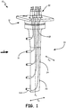
- Fig. 1 is a perspective view of pressure probe 10 which falls outside the scope of the claims.
- Pressure probe 10 includes base 12, airfoil 14, and kiels 16.
- Probe body 14 includes transition portion 18 and linear portion 20.
- Pressure probe 10 is arranged in the path of airstream A.
- Pressure probe 10 can be used to collect data regarding airstream A. Samples of airstream A may be transferred to remote sensors (not shown) via hypo tubing 22.
- Kiels 16 can be used to collect samples from airstream A and transmit those samples via internal tubing 24 to hypo tubing 22. Additionally, some data (such as pressure measurements) can be obtained by maintaining a fluid communication path between one of kiels 16 and a remote sensor (not shown), without necessitating routing of samples of airstream A through hypo tubing 22.
- Pressure probe 10 may be used in various portions of a gas turbine engine.
- pressure probe 10 may be configured to be deployed into airstream A that comprises the engine's core air flow.
- Pressure probe 10 is shaped substantially as an airfoil.
- pressure probe 10 is not designed to deflect airflow. Rather, pressure probe 10 is designed to be non-disruptive to the airstream in which it sits.
- Base 12 supports the rest of pressure probe 10 and engages with a surrounding duct 26 (as shown in Figs. 2A-2B ) in order to minimize losses of pressurized air at the location where pressure probe 10 enters the duct.
- base 12 is a substantially annular structure with a flange.
- Base 12 includes internal channels 24, which fluidically connect kiels 16 to hypo tubing 22.
- Airfoil 14 extends from base 12 along primary axis A X .
- Airfoil 14 is made of a metal, such as a high temperature superalloy, and airfoil 14 also contains internal channels 24. Airfoil 14 is non-deflecting, in that it is configured to minimally disrupt airstream A, as previously discussed.
- Kiels 16 extend from airfoil 14 in the upstream direction of airstream A. Kiels 16 are arranged in the direction of an expected airstream direction. As shown in Fig. 1 , the expected direction of airstream A (and, thus, the direction in which kiels 16 are arranged) is roughly perpendicular to primary axis A X .
- airfoil 14 first includes tapered portion 18 and then linear portion 20.
- Tapered portion 18 is a relatively thicker and structurally stronger than linear portion 20, and tapered portion 18 connects linear portion 20 to base 12.
- airfoil 14 tapers along both its chord dimension D C and its width dimension D W .
- chord dimension D C is 8% less at the intersection of tapered portion 18 and linear portion 20 than it is at the intersection of tapered portion 18 and base 12.
- width dimension D W is 20% less at the intersection of tapered portion 18 and linear portion 20 than it is at the intersection of tapered portion 18 and base 12. Because tapered portion 18 is thicker than linear portion 20 both in chord direction D C and width direction D W , tapered portion 18 is capable of supporting substantial loads applied to the entirety of airfoil 14 by airstream A.
- Hypo tubing 22 is arranged on the opposite side of base 12 from airfoil 14. Hypo tubing 22 can route air sampled from airstream A to a remote sensor (not shown). In some cases, such remote sensors can facilitate measurement of useful information by maintaining a fluid communication path between one of kiels 16 and a remote sensor (not shown), as previously described. For example, a pressure sensor may not require actual air samples, but merely a fluidic connection via hypo tubing 22 to one of kiels 16 and airstream A.
- Internal tubing 24 is shown in phantom.
- internal tubing 24 is routed (e.g., by coiling) as it passes between some of kiels 16 and hypo tubing 22 such that each internal tubing 24 has an equal length with the others. In this way, variation in samples that is dependent on the distance the sample travels through airfoil 14 can be managed or eliminated.
- Pressure probe 10 is additively manufactured, such that kiels 16 are monolithically formed with airfoil 14.
- pressure probe 10 may be manufactured using Direct Metal Laser Sintering.
- Monolithically forming kiels 16 with airfoil 14 eliminates an extra step in manufacturing, and eliminates the need for fittings, as well as eliminating a potential source of leaks between the inlet of kiels 16 and remote sensors (not shown).
- kiels 16 may be accurately aligned with the specific airstream A that is expected to pass by pressure probe 10.
- Kiels 16 that are monolithically formed with airfoil 14 exhibit relatively low drag and a minimal cross-section facing airstream A.
- Airfoil 14 also has a minimal cross-section facing airstream A (as described in more detail with respect to Fig. 2B ), and is designed to be non-deflecting, i.e., to impart negligible force on airstream A.
- pressure probe 10 may be shaped differently in order to be non-disruptive to the airstream for which it was designed.
- pressure probe 10 may follow a non-linear primary axis A X that is curved, angled, or twisted to orient kiels 16 in the expected direction of airstream A.
- Probe body 14 may be made of various materials in alternative embodiments. For example, in low temperature environments, probe body 14 need not be made of a high temperature super-alloy, but may instead be made of a metal alloy or a polymer.
- Pressure probe 10 may not always be positioned within airstream A. In some embodiments, pressure probe 10 is positioned within airstream A only during engine conditions when measurements are desired, such as during startup. During other engine conditions, pressure probe 10 can be retracted from airstream A.
- kiels 16 may face in different directions from one another depending on the expected direction of airstream A. For example, where airstream A includes vorticity or rotation, such that the expected direction of airstream A varies, kiels 16 may be configured such that they do not all face in the same direction, but rather in the direction of airstream A at that location along airfoil 14. As shown in Fig. 1 , kiel 16A faces in a different direction from the other kiels 16.
- pressure probe 10 may be a Mach probe, as described in more detail with respect to the embodiment shown in Figs. 4A-4B .
- Figs. 2A-2B illustrate pressure probe 10 of Fig. 1 from the upstream end and the side, respectively. Furthermore, Figs. 2A-2B illustrate the interaction of duct 26 with pressure probe 10.
- Fig. 2A is a partial cross-sectional view that illustrates pressure probe 10 of Fig. 1 .
- Pressure probe 10 is shown as previously described with respect to Fig. 1 .
- airfoil 14 is shown in planform.
- Fig. 2A further illustrates base 12 engaged with duct 26, which is shown in cross-section.
- Duct 26 is a wall that contains airstream A.
- duct 26 may be a composite duct containing the core airflow of a gas turbine engine. Often, duct 26 forms a closed annular structure.
- Fig. 2A includes cross-section 3A-3A, as further described with respect to Fig. 3A .
- airstream A is contained by duct 26, and passes by airfoil 14 and kiels 16.
- Kiels 16 are arranged to face in an expected direction of oncoming airflow that forms airstream A.
- Base 12 is configured to engage with duct 26 to prevent egress of airstream A.
- Fig. 2B is a partial cross-sectional view that also illustrates pressure probe 10 of Fig. 1 .
- Fig. 2B shows pressure probe 10 from the perspective of the oncoming airstream A.
- the cross-sectional area of airfoil 14 as seen from this perspective is minimized. Futhermore, it is apparent from Fig. 2B that airfoil 14 does not deflect airstream. As illustrated in Fig. 2B , airfoil 14 has no camber, and its angle of attack within airstream is zero.
- airfoil 14 may have camber or curvature depending on the expected direction of airstream A. While the direction of airstream A may vary depending on flight phase, airfoil 14 is designed to minimize the amount of deflection of airstream A. This design is desirable in those sensing applications where deflection of airstream A is unnecessary, and drag on airstream A is undesirable.
- Fig. 3A is a cross-sectional view of pressure probe 10, taken along line 3A-3A of Fig. 2A .
- pressure probe 10 includes base 12, airfoil 14, and kiels 16.
- Airfoil 14 includes tapered portion 18 and linear portion 20.
- Fig. 3A also illustrates internal channels 24, which pass through base 12 and airfoil 14 in order to fluidically connect kiels 16 with hypo tubing 22.
- internal channels 24 pass through the interior of airfoil 14 and base 12. By routing internal channels 24 through the interior of airfoil 14, disruption of airstream A is minimized.
- Additively manufacturing pressure probe 10 allows for highly complex internal passages 24.
- internal passages 24 of pressure probe 10 may be non-linear passageways that include serpentine sections, such that internal passages 24 each have an equal length to one another. Thus, pressure drop caused by internal passages 24 can be standardized between kiels 16 and hypo tubing 22.
- Fig. 3B is a cross-sectional view of pressure probe 10, taken along section 3B-3B of Fig. 2B , passing through linear portion 20.
- kiel 16 is bisected to show first internal passage 24A passing through it.
- the cross-section shown in Fig. 3B further shows second internal passage 24B, which traverses a path between kiel 16A ( Fig. 3A ) and base 12 ( Fig. 3A ).
- Fig. 4 is a schematic view of Mach probe 110 within airstream B which falls outside the scope of the claims.
- Mach probe includes base 112, airfoil 114, and kiels 116, as previously described with respect to Fig. 1 . Slight differences in the structures exist based on the different technical requirements of a Mach probe from a pressure probe. For example, kiels 116 comprise a cutout portion of the leading edge of airfoil 114, rather than a superstructure built onto that edge as shown with respect to the pressure probe of Fig. 1 .
- Mach probe 110 also includes side ports 117, which route samples of airstream B from the center (chordwise) of the planform of airfoil 114 to a remote sensor (not shown). Airfoil 114 includes tapered portion 118 and linear portion 120. Mach probe 110 is coupled with hypo tubing 122, which is used to route information regarding airstream B to remote sensors (not shown), such as plasma flow sensors, pressure sensors, and/or temperature sensors.
- Mach probe 110 is similar to pressure probe 10, and is used to determine a Mach number of the aircraft. Mach probe 110 is configured to be placed in duct 126 ( Fig. 5A ). Mach probes generally must be aligned with the flow path in order to prevent false Mach number readings. Additively manufacturing Mach probe 110 allows for internal passages 124 ( Fig. 4B ) that are non-linear, such that Mach probe 110 may also be non-linear. Mach probes typically route air from both the leading edge of airfoil 114 and the center (chordwise) of the planform of airfoil 114. Samples of each portion of airstream B are routed in separate tubes from one another. However, several kiels 116 each feed the same internal tube 124A, and each of side ports 117 feed the same internal tube 124B. Accordingly, Mach probe 110 may be oriented within the flow path of airstream B.
- Non-linear Mach probes such as Mach probe 110 are capable of generating highly accurate Mach number readings, as well as minimizing inefficiencies and downstream wakes, as previously discussed with reference to the pressure probe of Fig. 1 .
- Additively manufacturing Mach probe 110 allows for built-in internal passages, which may be non-linear and allow for orientation of Mach probe 110 with the flow path of airstream B.
- Fig. 5A is a cross-sectional view of Mach probe 110.
- Fig. 5A illustrates how Mach probe 110 is configured to fit within duct 126. Mach probe 110 and duct 126 engage to prevent egress of airstream B from duct 126.
- Fig. 5B is a cross-sectional view of Mach probe 110 of Fig. 4 , illustrating tubing 124A for the portion of airstream B routed from the leading edge of airfoil 114 via kiels 116. Side ports 117 are configured to route air from the center (chordwise) of the planform of airfoil 114 to a second tubing 124B.
- Fig. 5B illustrates another benefit of additively manufacturing Mach probe 110.
- the cross-section of tubing 124A is nearly triangular.
- tubing 124B, kiels 116, and/or side ports 117 may have various shapes or cross-sections that were previously difficult or impossible to create, using traditional subtractive manufacturing techniques.
- Such patterns can be used to promote or inhibit laminar flow, or to increase or decrease pressure drop from kiels and/or side ports 117 to remote sensors.
Claims (4)
- Drucksonde (10), umfassend:ein Schaufelprofil (14), das aus einem Metall hergestellt und konfiguriert ist zur Verwendung in einem Gasturbinentriebwerk, wobei das Schaufelprofil (14) keine Wölbung aufweist und so konfiguriert ist, dass sie während des Betriebs einen Anstellwinkel von null mit einem Luftstrom aufweist, und sich von einer Basis (12) zu einem verjüngten Abschnitt (18) zu einem linearen Abschnitt (20) entlang einer Hauptachse (AX) erstreckt, wobei das Schaufelprofil (14) einen konstanten Querschnitt in dem linearen Abschnitt (20) aufweist;eine Vielzahl von Kielsonden (16), die mit dem Schaufelprofil (14) monolithisch ausgebildet ist und wobei jede entsprechend ausgerichtet ist, um während des Betriebs in eine erwartete Luftstromrichtung (A) zu weisen; undeine Vielzahl von inneren Durchgängen (24), wobei jeder mit einer unterschiedlichen einen der Vielzahl von Kielsonden (16) wirkverbunden ist und sowohl durch das Schaufelprofil (14) als auch die Basis (12) verläuft;dadurch gekennzeichnet, dass:
die inneren Durchgänge (24) gleiche Durchgangslängen aufweisen. - Drucksonde (10) nach Anspruch 1, wobei die Basis (12) dazu konfiguriert ist, mit einer Vielzahl von Hypotubes (22) gekoppelt zu sein.
- Drucksonde (10) nach einem der vorstehenden Ansprüche, wobei mindestens eine der Vielzahl von Kielsonden (16) in eine unterschiedliche Richtung von anderen der Vielzahl von Kielsonden (16) weist.
- Drucksonde (10) nach einem der vorstehenden Ansprüche, wobei das Schaufelprofil (14) eine Sehnenabmessung (DC) und eine Breitenabmessung (DW) aufweist, die entlang der Hauptachse (AX) variieren, sodass:die Sehnenabmessung (DC) am Schnittpunkt des verjüngten Abschnitts (18) und des linearen Abschnitts (20) um 8 % geringer ist als am Schnittpunkt des verjüngten Abschnitts (18) und der Basis (12); unddie Breitenabmessung (DW) am Schnittpunkt des verjüngten Abschnitts (18) und des linearen Abschnitts (20) um 20 % geringer ist als am Schnittpunkt des verjüngten Abschnitts (18) und der Basis (12).
Applications Claiming Priority (2)
| Application Number | Priority Date | Filing Date | Title |
|---|---|---|---|
| US201461936032P | 2014-02-05 | 2014-02-05 | |
| PCT/US2015/012708 WO2015119792A1 (en) | 2014-02-05 | 2015-01-23 | Integral instrumentation in additively manufactured components of gas turbine engines |
Publications (3)
| Publication Number | Publication Date |
|---|---|
| EP3102806A1 EP3102806A1 (de) | 2016-12-14 |
| EP3102806A4 EP3102806A4 (de) | 2017-05-31 |
| EP3102806B1 true EP3102806B1 (de) | 2020-09-09 |
Family
ID=53778339
Family Applications (1)
| Application Number | Title | Priority Date | Filing Date |
|---|---|---|---|
| EP15746520.4A Active EP3102806B1 (de) | 2014-02-05 | 2015-01-23 | Drucksonde für gasturbine |
Country Status (3)
| Country | Link |
|---|---|
| US (1) | US10151214B2 (de) |
| EP (1) | EP3102806B1 (de) |
| WO (1) | WO2015119792A1 (de) |
Families Citing this family (26)
| Publication number | Priority date | Publication date | Assignee | Title |
|---|---|---|---|---|
| FR3017459B1 (fr) * | 2014-02-07 | 2017-07-21 | Snecma | Aube instrumentee a tube rapporte dans une rainure |
| US9856743B2 (en) * | 2014-05-28 | 2018-01-02 | Safran Aircraft Engines | Instrumented flow passage of a turbine engine |
| RU2017134423A (ru) * | 2015-04-23 | 2019-05-23 | Нуово Пиньоне Текнолоджи Срл | Измерение полного давления текучей среды в турбомашине |
| DE102016005596A1 (de) * | 2015-10-15 | 2017-04-20 | Kiefel Gmbh | Befüllvorrichtung zum befüllen eines medizinischen beutels, verfahren zum herstellen einer derartigen befüllvorrichtung sowie anlage zum herstellen von mit fluiden befüllten medizinischen beuteln |
| FR3043464B1 (fr) * | 2015-11-06 | 2017-11-10 | Snecma | Dispositif de mesure pour une veine d'ecoulement de gaz d'une turbomachine |
| FR3044412B1 (fr) * | 2015-11-30 | 2018-11-09 | Safran Aircraft Engines | Veine instrumentee de turbomachine |
| CN105547581A (zh) * | 2015-12-15 | 2016-05-04 | 中国燃气涡轮研究院 | 一种实现叶轮机转子出口压力云图的制作方法 |
| US10794281B2 (en) * | 2016-02-02 | 2020-10-06 | General Electric Company | Gas turbine engine having instrumented airflow path components |
| US10753278B2 (en) | 2016-03-30 | 2020-08-25 | General Electric Company | Translating inlet for adjusting airflow distortion in gas turbine engine |
| US11073090B2 (en) | 2016-03-30 | 2021-07-27 | General Electric Company | Valved airflow passage assembly for adjusting airflow distortion in gas turbine engine |
| CN106500904B (zh) * | 2016-10-08 | 2019-02-15 | 中国科学院工程热物理研究所 | 一种基于增材制造的气流探针制作方法 |
| US11285711B2 (en) * | 2017-04-18 | 2022-03-29 | General Electric Company | Adhesion of a substrate onto a CMC component |
| CN107132000B (zh) * | 2017-05-08 | 2019-02-26 | 北京航空航天大学 | 一种带有吹气支杆结构的压力探针梳 |
| KR101868899B1 (ko) * | 2017-05-17 | 2018-06-20 | 국방과학연구소 | 평균 전압력 계측 프로브 |
| FR3066779B1 (fr) * | 2017-05-26 | 2020-04-03 | Safran Aircraft Engines | Dispositif de mesure de parametres d'un flux aerodynamique pour pale de turbomachine, pale et organe de turbomachine equipes dudit dispositif de mesure |
| FR3072169B1 (fr) * | 2017-10-09 | 2019-10-11 | Safran Aircraft Engines | Dispositif de mesure d'au moins un parametre d'un flux aerodynamique d'une turbomachine equipe d'un moyen d'amortissement vibratoire et veine de turbomachine equipee d'un tel dispositif |
| US10598041B2 (en) * | 2017-10-20 | 2020-03-24 | United Technologies Corporation | Inlet performance measurement system for gas turbine engine |
| US10717514B2 (en) * | 2018-03-09 | 2020-07-21 | Senior Ip Gmbh | Integrated drain mast structure |
| US10890501B2 (en) | 2018-10-19 | 2021-01-12 | Hamilton Sunstrand Corporation | Additive manufacturing integrated instrumentation design for improved static pressure measurements |
| KR102047980B1 (ko) * | 2019-04-29 | 2019-11-22 | 국방과학연구소 | 고온 전압력 측정 프로브 |
| US11655726B2 (en) * | 2020-02-28 | 2023-05-23 | Rosemount Aerospace Inc. | Pressure and temperature sensors and related methods |
| US11879345B2 (en) | 2020-02-28 | 2024-01-23 | Rosemount Aerospace Inc. | Pressure and temperature sensors and methods of removing ice from pressure and temperature sensors |
| US11773745B2 (en) | 2020-02-28 | 2023-10-03 | Rosemount Aerospace Inc. | Pressure and temperature sensors and methods of controlling ice accretion on pressure and temperature sensors |
| CN113156172B (zh) * | 2021-04-20 | 2022-07-29 | 核工业西南物理研究院 | 一种多台阶式静电探针探头 |
| EP4324736A1 (de) * | 2022-08-15 | 2024-02-21 | BAE SYSTEMS plc | Gerät zur durchflussmessung |
| WO2024038249A1 (en) * | 2022-08-15 | 2024-02-22 | Bae Systems Plc | Apparatus for flow measurement |
Family Cites Families (10)
| Publication number | Priority date | Publication date | Assignee | Title |
|---|---|---|---|---|
| US4433584A (en) * | 1981-11-27 | 1984-02-28 | United Technologies Corp. | Total pressure probe |
| US4605315A (en) * | 1984-12-13 | 1986-08-12 | United Technologies Corporation | Temperature probe for rotating machinery |
| US4733975A (en) * | 1986-07-03 | 1988-03-29 | The United States Of America As Represented By The Secretary Of The Air Force | Unitized high temperature probes |
| US4765751A (en) | 1987-06-29 | 1988-08-23 | United Technologies Corporation | Temperature and pressure probe |
| US6305218B1 (en) * | 1999-02-22 | 2001-10-23 | Rosemount Aerospace Inc. | Method of and apparatus for using an alternate pressure to measure mach number at high probe angles of attack |
| US7328623B2 (en) | 2006-03-20 | 2008-02-12 | General Electric Company | Temperature and/or pressure sensor assembly |
| GB2452026B (en) | 2007-07-27 | 2010-05-05 | Assystem | Instrumentation rake and aerofoil having instrumentation elements and method of manufacture therefor |
| DE102008025869A1 (de) | 2008-05-31 | 2009-12-03 | Mtu Aero Engines Gmbh | Messsonde und Verfahren zur Herstellung einer Messsonde |
| FR2952713B1 (fr) * | 2009-11-16 | 2014-01-03 | Snecma | Procede de fabrication d'un peigne de mesure comportant des moyens de mesure aptes a la mesure de parametres dans un flux d'air de turboreacteur experimental |
| US8839662B2 (en) | 2011-06-27 | 2014-09-23 | United Technologies Corporation | Station probe for gas turbine engines |
-
2015
- 2015-01-23 WO PCT/US2015/012708 patent/WO2015119792A1/en active Application Filing
- 2015-01-23 US US15/114,013 patent/US10151214B2/en active Active
- 2015-01-23 EP EP15746520.4A patent/EP3102806B1/de active Active
Also Published As
| Publication number | Publication date |
|---|---|
| WO2015119792A1 (en) | 2015-08-13 |
| US10151214B2 (en) | 2018-12-11 |
| EP3102806A4 (de) | 2017-05-31 |
| EP3102806A1 (de) | 2016-12-14 |
| US20160348531A1 (en) | 2016-12-01 |
Similar Documents
| Publication | Publication Date | Title |
|---|---|---|
| EP3102806B1 (de) | Drucksonde für gasturbine | |
| US11731782B2 (en) | Bulkheads for air data probes | |
| EP2700952B1 (de) | Feuchtigkeitsbeständige Luftdatensonden | |
| EP2848904B1 (de) | Überkritische Gesamtlufttemperatursensoren | |
| EP3073276B1 (de) | Luftdatensonde mit verbesserter leistung beim betrieb unter einem hohen anstellwinkel | |
| IT8224405A1 (it) | Metodo per misurare la pressione totale di un fluido e sonda per effettuare tale misurazione | |
| US20140182292A1 (en) | Integral instrumentation in additively manufactured components of gas turbine engines | |
| GB2452026A (en) | Aerofoil or instrumentation rake with integrally formed instrumentation elements | |
| Clari et al. | Three-dimensional flow separations in the diffuser of a steam turbine control valve | |
| EP3301417B1 (de) | Abgastemperaturfühlersondenanordnung | |
| Tiedemann et al. | A new linear high speed compressor stator cascade for active flow control investigations | |
| CN111140542A (zh) | 一种基元级前缘自带三个感压孔的榫式叶片 | |
| EP3301418B1 (de) | Abgastemperaturmesssondenanordnung | |
| EP3301419A1 (de) | Abgastemperaturmesssondenanordnung | |
| Chernoray et al. | Improving the accuracy of multihole probe measurements in velocity gradients | |
| EP3415923B1 (de) | Generativ gefertigter durchflussmesssensor | |
| Luxa et al. | Pneumatic measurements downstream of a radial turbine nozzle cascade | |
| CN212454963U (zh) | 一种基元级前缘自带三个感压孔的榫式叶片 | |
| JP2008089329A (ja) | 圧力分布測定装置 | |
| Winter et al. | A Comment on the Origin of Endwall Interference in Wind-tunnel Tests of Aerofoils | |
| Smith et al. | Aerodynamic correlations for a fin with a vortex-induced angle of attack | |
| IM A | This work was performed under Grant NSn-2288 and NGL 10-005-12" for the National Aeronautics and Space Administration, Ames Research Center, Moffett Field, CA, and Langley Research Center, Hampton, YA | |
| Auletta et al. | Wall Corrections for CIRA Icing Wind Tunnel Secondary Test Section-Equipment Design, Realization and Performance Evaluation | |
| CZ259299A3 (cs) | Pilotova statická trubice pro trup letadla a “ aerodynamický profil její vzpěry | |
| CS210084B1 (cs) | Směrová sonda |
Legal Events
| Date | Code | Title | Description |
|---|---|---|---|
| PUAI | Public reference made under article 153(3) epc to a published international application that has entered the european phase |
Free format text: ORIGINAL CODE: 0009012 |
|
| STAA | Information on the status of an ep patent application or granted ep patent |
Free format text: STATUS: REQUEST FOR EXAMINATION WAS MADE |
|
| 17P | Request for examination filed |
Effective date: 20160905 |
|
| AK | Designated contracting states |
Kind code of ref document: A1 Designated state(s): AL AT BE BG CH CY CZ DE DK EE ES FI FR GB GR HR HU IE IS IT LI LT LU LV MC MK MT NL NO PL PT RO RS SE SI SK SM TR |
|
| AX | Request for extension of the european patent |
Extension state: BA ME |
|
| RIC1 | Information provided on ipc code assigned before grant |
Ipc: B29C 67/00 20170101ALI20170119BHEP Ipc: F01D 25/00 20060101ALI20170119BHEP Ipc: G01L 19/00 20060101ALI20170119BHEP Ipc: G01P 5/175 20060101ALI20170119BHEP Ipc: F02C 7/00 20060101AFI20170119BHEP |
|
| DAX | Request for extension of the european patent (deleted) | ||
| A4 | Supplementary search report drawn up and despatched |
Effective date: 20170428 |
|
| RIC1 | Information provided on ipc code assigned before grant |
Ipc: B29C 67/00 20170101ALI20170421BHEP Ipc: F01D 25/00 20060101ALI20170421BHEP Ipc: G01P 5/175 20060101ALI20170421BHEP Ipc: G01L 19/00 20060101ALI20170421BHEP Ipc: F02C 7/00 20060101AFI20170421BHEP |
|
| STAA | Information on the status of an ep patent application or granted ep patent |
Free format text: STATUS: EXAMINATION IS IN PROGRESS |
|
| 17Q | First examination report despatched |
Effective date: 20190128 |
|
| GRAP | Despatch of communication of intention to grant a patent |
Free format text: ORIGINAL CODE: EPIDOSNIGR1 |
|
| STAA | Information on the status of an ep patent application or granted ep patent |
Free format text: STATUS: GRANT OF PATENT IS INTENDED |
|
| INTG | Intention to grant announced |
Effective date: 20200414 |
|
| GRAS | Grant fee paid |
Free format text: ORIGINAL CODE: EPIDOSNIGR3 |
|
| GRAA | (expected) grant |
Free format text: ORIGINAL CODE: 0009210 |
|
| STAA | Information on the status of an ep patent application or granted ep patent |
Free format text: STATUS: THE PATENT HAS BEEN GRANTED |
|
| AK | Designated contracting states |
Kind code of ref document: B1 Designated state(s): AL AT BE BG CH CY CZ DE DK EE ES FI FR GB GR HR HU IE IS IT LI LT LU LV MC MK MT NL NO PL PT RO RS SE SI SK SM TR |
|
| REG | Reference to a national code |
Ref country code: GB Ref legal event code: FG4D |
|
| REG | Reference to a national code |
Ref country code: AT Ref legal event code: REF Ref document number: 1311859 Country of ref document: AT Kind code of ref document: T Effective date: 20200915 Ref country code: CH Ref legal event code: EP |
|
| REG | Reference to a national code |
Ref country code: IE Ref legal event code: FG4D |
|
| REG | Reference to a national code |
Ref country code: DE Ref legal event code: R096 Ref document number: 602015058790 Country of ref document: DE |
|
| REG | Reference to a national code |
Ref country code: LT Ref legal event code: MG4D |
|
| PG25 | Lapsed in a contracting state [announced via postgrant information from national office to epo] |
Ref country code: NO Free format text: LAPSE BECAUSE OF FAILURE TO SUBMIT A TRANSLATION OF THE DESCRIPTION OR TO PAY THE FEE WITHIN THE PRESCRIBED TIME-LIMIT Effective date: 20201209 Ref country code: FI Free format text: LAPSE BECAUSE OF FAILURE TO SUBMIT A TRANSLATION OF THE DESCRIPTION OR TO PAY THE FEE WITHIN THE PRESCRIBED TIME-LIMIT Effective date: 20200909 Ref country code: GR Free format text: LAPSE BECAUSE OF FAILURE TO SUBMIT A TRANSLATION OF THE DESCRIPTION OR TO PAY THE FEE WITHIN THE PRESCRIBED TIME-LIMIT Effective date: 20201210 Ref country code: LT Free format text: LAPSE BECAUSE OF FAILURE TO SUBMIT A TRANSLATION OF THE DESCRIPTION OR TO PAY THE FEE WITHIN THE PRESCRIBED TIME-LIMIT Effective date: 20200909 Ref country code: HR Free format text: LAPSE BECAUSE OF FAILURE TO SUBMIT A TRANSLATION OF THE DESCRIPTION OR TO PAY THE FEE WITHIN THE PRESCRIBED TIME-LIMIT Effective date: 20200909 Ref country code: SE Free format text: LAPSE BECAUSE OF FAILURE TO SUBMIT A TRANSLATION OF THE DESCRIPTION OR TO PAY THE FEE WITHIN THE PRESCRIBED TIME-LIMIT Effective date: 20200909 Ref country code: BG Free format text: LAPSE BECAUSE OF FAILURE TO SUBMIT A TRANSLATION OF THE DESCRIPTION OR TO PAY THE FEE WITHIN THE PRESCRIBED TIME-LIMIT Effective date: 20201209 |
|
| REG | Reference to a national code |
Ref country code: AT Ref legal event code: MK05 Ref document number: 1311859 Country of ref document: AT Kind code of ref document: T Effective date: 20200909 |
|
| REG | Reference to a national code |
Ref country code: NL Ref legal event code: MP Effective date: 20200909 |
|
| PG25 | Lapsed in a contracting state [announced via postgrant information from national office to epo] |
Ref country code: PL Free format text: LAPSE BECAUSE OF FAILURE TO SUBMIT A TRANSLATION OF THE DESCRIPTION OR TO PAY THE FEE WITHIN THE PRESCRIBED TIME-LIMIT Effective date: 20200909 Ref country code: LV Free format text: LAPSE BECAUSE OF FAILURE TO SUBMIT A TRANSLATION OF THE DESCRIPTION OR TO PAY THE FEE WITHIN THE PRESCRIBED TIME-LIMIT Effective date: 20200909 Ref country code: RS Free format text: LAPSE BECAUSE OF FAILURE TO SUBMIT A TRANSLATION OF THE DESCRIPTION OR TO PAY THE FEE WITHIN THE PRESCRIBED TIME-LIMIT Effective date: 20200909 |
|
| RAP2 | Party data changed (patent owner data changed or rights of a patent transferred) |
Owner name: RAYTHEON TECHNOLOGIES CORPORATION |
|
| PG25 | Lapsed in a contracting state [announced via postgrant information from national office to epo] |
Ref country code: EE Free format text: LAPSE BECAUSE OF FAILURE TO SUBMIT A TRANSLATION OF THE DESCRIPTION OR TO PAY THE FEE WITHIN THE PRESCRIBED TIME-LIMIT Effective date: 20200909 Ref country code: RO Free format text: LAPSE BECAUSE OF FAILURE TO SUBMIT A TRANSLATION OF THE DESCRIPTION OR TO PAY THE FEE WITHIN THE PRESCRIBED TIME-LIMIT Effective date: 20200909 Ref country code: PT Free format text: LAPSE BECAUSE OF FAILURE TO SUBMIT A TRANSLATION OF THE DESCRIPTION OR TO PAY THE FEE WITHIN THE PRESCRIBED TIME-LIMIT Effective date: 20210111 Ref country code: SM Free format text: LAPSE BECAUSE OF FAILURE TO SUBMIT A TRANSLATION OF THE DESCRIPTION OR TO PAY THE FEE WITHIN THE PRESCRIBED TIME-LIMIT Effective date: 20200909 Ref country code: NL Free format text: LAPSE BECAUSE OF FAILURE TO SUBMIT A TRANSLATION OF THE DESCRIPTION OR TO PAY THE FEE WITHIN THE PRESCRIBED TIME-LIMIT Effective date: 20200909 Ref country code: CZ Free format text: LAPSE BECAUSE OF FAILURE TO SUBMIT A TRANSLATION OF THE DESCRIPTION OR TO PAY THE FEE WITHIN THE PRESCRIBED TIME-LIMIT Effective date: 20200909 |
|
| PG25 | Lapsed in a contracting state [announced via postgrant information from national office to epo] |
Ref country code: IS Free format text: LAPSE BECAUSE OF FAILURE TO SUBMIT A TRANSLATION OF THE DESCRIPTION OR TO PAY THE FEE WITHIN THE PRESCRIBED TIME-LIMIT Effective date: 20210109 Ref country code: AL Free format text: LAPSE BECAUSE OF FAILURE TO SUBMIT A TRANSLATION OF THE DESCRIPTION OR TO PAY THE FEE WITHIN THE PRESCRIBED TIME-LIMIT Effective date: 20200909 Ref country code: AT Free format text: LAPSE BECAUSE OF FAILURE TO SUBMIT A TRANSLATION OF THE DESCRIPTION OR TO PAY THE FEE WITHIN THE PRESCRIBED TIME-LIMIT Effective date: 20200909 Ref country code: ES Free format text: LAPSE BECAUSE OF FAILURE TO SUBMIT A TRANSLATION OF THE DESCRIPTION OR TO PAY THE FEE WITHIN THE PRESCRIBED TIME-LIMIT Effective date: 20200909 |
|
| REG | Reference to a national code |
Ref country code: DE Ref legal event code: R097 Ref document number: 602015058790 Country of ref document: DE |
|
| PG25 | Lapsed in a contracting state [announced via postgrant information from national office to epo] |
Ref country code: SK Free format text: LAPSE BECAUSE OF FAILURE TO SUBMIT A TRANSLATION OF THE DESCRIPTION OR TO PAY THE FEE WITHIN THE PRESCRIBED TIME-LIMIT Effective date: 20200909 |
|
| PLBE | No opposition filed within time limit |
Free format text: ORIGINAL CODE: 0009261 |
|
| STAA | Information on the status of an ep patent application or granted ep patent |
Free format text: STATUS: NO OPPOSITION FILED WITHIN TIME LIMIT |
|
| 26N | No opposition filed |
Effective date: 20210610 |
|
| PG25 | Lapsed in a contracting state [announced via postgrant information from national office to epo] |
Ref country code: DK Free format text: LAPSE BECAUSE OF FAILURE TO SUBMIT A TRANSLATION OF THE DESCRIPTION OR TO PAY THE FEE WITHIN THE PRESCRIBED TIME-LIMIT Effective date: 20200909 Ref country code: MC Free format text: LAPSE BECAUSE OF FAILURE TO SUBMIT A TRANSLATION OF THE DESCRIPTION OR TO PAY THE FEE WITHIN THE PRESCRIBED TIME-LIMIT Effective date: 20200909 Ref country code: SI Free format text: LAPSE BECAUSE OF FAILURE TO SUBMIT A TRANSLATION OF THE DESCRIPTION OR TO PAY THE FEE WITHIN THE PRESCRIBED TIME-LIMIT Effective date: 20200909 |
|
| REG | Reference to a national code |
Ref country code: CH Ref legal event code: PL |
|
| PG25 | Lapsed in a contracting state [announced via postgrant information from national office to epo] |
Ref country code: LU Free format text: LAPSE BECAUSE OF NON-PAYMENT OF DUE FEES Effective date: 20210123 |
|
| REG | Reference to a national code |
Ref country code: BE Ref legal event code: MM Effective date: 20210131 |
|
| PG25 | Lapsed in a contracting state [announced via postgrant information from national office to epo] |
Ref country code: IT Free format text: LAPSE BECAUSE OF FAILURE TO SUBMIT A TRANSLATION OF THE DESCRIPTION OR TO PAY THE FEE WITHIN THE PRESCRIBED TIME-LIMIT Effective date: 20200909 |
|
| PG25 | Lapsed in a contracting state [announced via postgrant information from national office to epo] |
Ref country code: CH Free format text: LAPSE BECAUSE OF NON-PAYMENT OF DUE FEES Effective date: 20210131 Ref country code: LI Free format text: LAPSE BECAUSE OF NON-PAYMENT OF DUE FEES Effective date: 20210131 |
|
| PG25 | Lapsed in a contracting state [announced via postgrant information from national office to epo] |
Ref country code: IE Free format text: LAPSE BECAUSE OF NON-PAYMENT OF DUE FEES Effective date: 20210123 |
|
| PG25 | Lapsed in a contracting state [announced via postgrant information from national office to epo] |
Ref country code: BE Free format text: LAPSE BECAUSE OF NON-PAYMENT OF DUE FEES Effective date: 20210131 |
|
| PG25 | Lapsed in a contracting state [announced via postgrant information from national office to epo] |
Ref country code: HU Free format text: LAPSE BECAUSE OF FAILURE TO SUBMIT A TRANSLATION OF THE DESCRIPTION OR TO PAY THE FEE WITHIN THE PRESCRIBED TIME-LIMIT; INVALID AB INITIO Effective date: 20150123 |
|
| PGFP | Annual fee paid to national office [announced via postgrant information from national office to epo] |
Ref country code: DE Payment date: 20221220 Year of fee payment: 9 |
|
| P01 | Opt-out of the competence of the unified patent court (upc) registered |
Effective date: 20230520 |
|
| PG25 | Lapsed in a contracting state [announced via postgrant information from national office to epo] |
Ref country code: CY Free format text: LAPSE BECAUSE OF FAILURE TO SUBMIT A TRANSLATION OF THE DESCRIPTION OR TO PAY THE FEE WITHIN THE PRESCRIBED TIME-LIMIT Effective date: 20200909 |
|
| PGFP | Annual fee paid to national office [announced via postgrant information from national office to epo] |
Ref country code: GB Payment date: 20231219 Year of fee payment: 10 |
|
| PGFP | Annual fee paid to national office [announced via postgrant information from national office to epo] |
Ref country code: FR Payment date: 20231219 Year of fee payment: 10 |