EP3102364B1 - Tensioner - Google Patents
Tensioner Download PDFInfo
- Publication number
- EP3102364B1 EP3102364B1 EP14710046.5A EP14710046A EP3102364B1 EP 3102364 B1 EP3102364 B1 EP 3102364B1 EP 14710046 A EP14710046 A EP 14710046A EP 3102364 B1 EP3102364 B1 EP 3102364B1
- Authority
- EP
- European Patent Office
- Prior art keywords
- tensioner
- sleeve
- thread
- base
- body portion
- Prior art date
- Legal status (The legal status is an assumption and is not a legal conclusion. Google has not performed a legal analysis and makes no representation as to the accuracy of the status listed.)
- Active
Links
Images


Classifications
-
- B—PERFORMING OPERATIONS; TRANSPORTING
- B23—MACHINE TOOLS; METAL-WORKING NOT OTHERWISE PROVIDED FOR
- B23P—METAL-WORKING NOT OTHERWISE PROVIDED FOR; COMBINED OPERATIONS; UNIVERSAL MACHINE TOOLS
- B23P19/00—Machines for simply fitting together or separating metal parts or objects, or metal and non-metal parts, whether or not involving some deformation; Tools or devices therefor so far as not provided for in other classes
- B23P19/04—Machines for simply fitting together or separating metal parts or objects, or metal and non-metal parts, whether or not involving some deformation; Tools or devices therefor so far as not provided for in other classes for assembling or disassembling parts
- B23P19/06—Screw or nut setting or loosening machines
- B23P19/067—Bolt tensioners
-
- B—PERFORMING OPERATIONS; TRANSPORTING
- B25—HAND TOOLS; PORTABLE POWER-DRIVEN TOOLS; MANIPULATORS
- B25B—TOOLS OR BENCH DEVICES NOT OTHERWISE PROVIDED FOR, FOR FASTENING, CONNECTING, DISENGAGING, OR HOLDING
- B25B29/00—Accessories
- B25B29/02—Bolt tensioners
-
- F—MECHANICAL ENGINEERING; LIGHTING; HEATING; WEAPONS; BLASTING
- F16—ENGINEERING ELEMENTS AND UNITS; GENERAL MEASURES FOR PRODUCING AND MAINTAINING EFFECTIVE FUNCTIONING OF MACHINES OR INSTALLATIONS; THERMAL INSULATION IN GENERAL
- F16B—DEVICES FOR FASTENING OR SECURING CONSTRUCTIONAL ELEMENTS OR MACHINE PARTS TOGETHER, e.g. NAILS, BOLTS, CIRCLIPS, CLAMPS, CLIPS OR WEDGES; JOINTS OR JOINTING
- F16B31/00—Screwed connections specially modified in view of tensile load; Break-bolts
- F16B31/04—Screwed connections specially modified in view of tensile load; Break-bolts for maintaining a tensile load
- F16B31/043—Prestressed connections tensioned by means of liquid, grease, rubber, explosive charge, or the like
-
- G—PHYSICS
- G01—MEASURING; TESTING
- G01L—MEASURING FORCE, STRESS, TORQUE, WORK, MECHANICAL POWER, MECHANICAL EFFICIENCY, OR FLUID PRESSURE
- G01L1/00—Measuring force or stress, in general
- G01L1/12—Measuring force or stress, in general by measuring variations in the magnetic properties of materials resulting from the application of stress
Definitions
- This invention relates to a tensioner of threaded members according to the preamble of claim 1.
- Tensioners are commonly used for, amongst other tasks, stretching items such as bolts or studs, so that a threaded nut can then be run down the stretched bolt, thus capturing the tension in the stretched bolt.
- they are used in any field that requires large loads to be secured by the use of threaded fasteners; one common use is in wind turbines, when such tensioners can be used to secure many fastenings, such as the turbine blades to their bearing, or the tower of such a turbine to its foundations.
- Hydraulic tensioners are well known in the art; examples of the same can be seen in the European Patent Application published as EP 2 522 465 and in the Japanese Patent Application published as JP3-204406 .
- the latter document discloses a tensioner for threaded members according to the preamble of claim 1.
- tensioners can be used to stretch a threaded member such as a stud, bolt or the like, and generally comprise inner and outer coaxial generally cylindrical annular bodies which are placed around the threaded member.
- the inner body threadedly engages the threaded member.
- a space between the inner and outer bodies defines a pressure space, into which fluid, typically hydraulic fluid, can be introduced to drive the bodies apart along their common axis.
- the piston on introduction of the fluid into the pressure space, will be urged away from the base along the threaded member, so as to place the threaded member in tension. If a nut is run along the threaded member to abut the fixed surface, the tension generated in the threaded member can be stored and applied to the fixed surface. The bolt tensioner can then be released and removed, leaving a fastened nut and threaded member.
- the threaded member and nut can be used to fasten a plurality of objects together; this can be most easily be seen in the case where the threaded member is a bolt where a number of objects of sheet form can be held between the nut and the head of the bolt.
- the displacement sensor may be a linear encoder, where one of the first and second parts comprises a scale that encodes a position and the other of the first and second parts is a transducer that reads the scale. Because the first and second parts are mounted on parts that move relative to one other, the transducer will see movement of the scale, and so be able to measure the relative movement.
- the scale will be a magnetic encoder, with the scale encoded magnetically, for example as a series of alternating magnetic poles along the scale or by varying the magnetic permeability of the scale along its length.
- the transducer will be a magnetic field sensor, such as a Hall effect sensor.
- the scale can be encoded optically, capacitively or inductively, with the transducer being capable of reading such encodings.
- thread-engaging member will comprise a sleeve surrounding the body portion, the sleeve carrying the second part of the displacement sensor (typically the scale).
- the sleeve may be free to rotate around the body portion, but provided with a stop such that linear movement along the axis relative to the sleeve is restricted.
- the stop may comprise a retaining ring protruding from an outer surface of the body portion.
- the sleeve will advantageously be fixed rotationally about the axis relative to the base. This will ensure that the two parts of the displacement sensor are appropriately rotationally located relative to one another as the thread-engaging member is screwed onto a threaded member, whilst still allowing the two parts to move linearly relative to one another along the axis, which is the displacement that it is desired to measure.
- the sleeve may be provided with at least one guide pin protruding from the sleeve and the base may have at least one slot formed therein running along the axis; each guide pin may be received in a corresponding slot.
- the pin working in the slot will allow linear movement along the axis, but restrict rotational movement of the sleeve relative to the base.
- the use of the sleeve ensures that the two parts of the displacement sensor are appropriately rotationally located relative to one another as the thread-engaging member is screwed onto a threaded member, whilst still allowing the two parts to move linearly relative to one another along the axis, which is the displacement that it is desired to measure.
- the relative movement of the two parts of the encoder is constrained to be one-dimensional, thus allowing a simpler, smaller and hence cheaper encoder arrangement to be used.
- storage of the sensor part is improved and risk of damage minimised.
- a sleeve will further facilitate the use of multiple different thread engaging members; only the sleeve will need to have the encoder mounted thereon, with multiple different thread engaging members enabling the use of the tensioner with different diameter threaded members, without the need for each thread-engaging member to have its own encoder.
- the displacement sensor may be provided with an output for the measured displacement.
- the output would comprise an output cable by means of which the measured displacement can be transmitted to a reader, display or other such terminal.
- the output may be provided with a wireless transmitter whereby the measured displacement can be transmitted to a remote location.
- the tensioner will be a hydraulic tensioner and will comprise a source of pressurised fluid in communication with the pressure space.
- the protrusion may be a flange on the thread-engaging member.
- the second portion of the displacement sensor will be positioned axially along the body portion on a portion of the body portion that is engaged with the thread of the threaded member. As such, this reduces further any errors due to elastic deformation of the tensioner itself.
- a hydraulic tensioner 1 in accordance with an embodiment of the invention is shown in the accompanying drawings.
- the tension can act to tension and so extend a threaded member of the form of a bolt or stud 2; a nut 3 can then be run down the bolt 2 in order to capture that tension.
- the tensioner comprises a base 4, which forms a housing for the tensioner and will rest against a fixed surface.
- the tensioner also comprises a piston 6, which can move relative to base 4 along central axis 17 through a bore 20.
- a pressure space 13 Between the base 4 and the piston 6 there is defined a pressure space 13. Hydraulic fluid can be introduced into this space by means of a system of ports 14. By doing so, the piston 6 can be forced away from the base 4; the piston 6 will move along axis 17, vertically in the sense of the Figures.
- the piston 6 has a central through bore 20, coaxial with the axis 17.
- a thread-engaging member 7 comprises a body portion 8 of the form of a cylindrical sleeve that fits within the bore 20.
- the interior of the sleeve defines a threaded bore 30, which engages the threaded member 2.
- the thread-engaging member 7 has a piston engaging portion 9 positioned at the end of the body portion 8. It forms a protrusion of the form of a flange, which abuts the piston 6 such that the force generated by the piston 6 being urged away from the base 4 is transmitted to the piston engaging portion 9, through body portion 8 and then through the threaded bore 20 to the threaded member 2.
- the nut 3 can then be run down threaded member 2 to keep the member 2 in tension and cause the nut 3 to press against the fixed surface once the tension due to the fluid in the pressure space 13 has been released.
- a sleeve 10 is provided around the external surface 5 of the body portion 8 of the thread-engaging member 7.
- the sleeve 10 is of the form of a cylindrical shell, coaxial with the axis 17. It is free to rotate relative to the thread-engaging member 7, but is retained against linear movement along the axis 17 by a retaining ring 27 protruding from the outer surface 5.
- This sleeve 10 carries a magnetic encoder strip 11 along its length, mounted in a recess 21 in the outer surface of the sleeve 10.
- the magnetic encoder is of the form of a pattern of magnetic poles, so that a pattern of magnetic fields projection axially outwards from the sleeve 10 is created.
- the length of the magnetic encoder 11 is aligned parallel to the axis 17.
- These magnetic fields can be read by a magnetic sensor 12 mounted in the base 4, which will typically be a Hall effect sensor.
- the magnetic sensor 12 is fixed relative to the base 4 by means of clamps 18.
- the magnetic encoder 11 will move past the magnetic sensor 12; by appropriate processing of the output (through output cable 19) it will be possible to measure the movement of the thread-engaging member 7 relative to the base 4 and from that determine the elongation of the threaded member 2.
- the measurement can involve simple counting of the reversals of the magnetic field as poles past, but the skilled man will appreciate that there are multiple ways in which position can be encoded magnetically.
- the encoder is mounted low down on the body 8 of the thread-engaging member 7, fewer errors are introduced into the measurement due to the elastic elongation of parts of the tensioner 1 such as the thread-engaging member. It can be seen that the magnetic encoder 11 is fitted on a portion of the body portion 8 that is engaging the threaded member, and so by measuring at that point these errors can be minimised.
- the sleeve 10 is provided with two protruding pins 15. These are received within corresponding elongate slots 16 in the base 4, the slots running parallel to the axis 17. As such, this substantially prevents the sleeve 10 from rotating about the axis 17 relative to the base 4 (although it can rotate relative to the thread-engaging member 7) whilst allowing the linear movement along the axis that it is desired to measure.
- the thread-engaging member 7 can be screwed onto the threaded member 2 without having to be concerned about the angular orientation of the magnetic encoder 11 relative to the magnetic sensor 12, as the pins 15 will ensure that that alignment is correct. If the magnetic encoder were directly carried on the body portion 8 of the thread-engaging member 7, then it would be necessary to ensure that the thread-engaging member was rotated to the correct position relative to the base on every installation, which would be labour-intensive and prone to inaccuracy.
- the output signal from the magnetic sensor 12 can be read out from output cable 19 and directed to a suitable processor. Whilst the processor, or the processed results, can be located local to the tensioner 1, it is also possible that the raw output signals or the processed results, or any intermediate results, could be transmitted wirelessly to a base station remote from the tensioner. This would be particularly useful where several tensioners were being used together (as such may be used in the bolts securing a wind turbine to the ground, or securing the turbine blades onto the nacelle) and it allows monitoring of several operations simultaneously, and also more flexibly recording the results for traceability's sake.
- the sleeve of this embodiment is fixed rotationally relative to the base, in another embodiment, it is possible to have the sleeve not rotationally fixed, so that the sleeve is free to rotate around the base.
- the encoder would encompass the entire circumferential surface of the sleeve, so that the elongation measurement could be taken regardless of the rotational relationship between the sleeve and the magnetic sensor.
- the sleeve would provide the advantage that it the sleeve could be used with multiple different thread-engaging members, rather than requiring each thread-engaging member (or each puller bar) for different sized threads having to be provided with the encoder; thus, only one item needs to be encoded, rather than multiple items.
Landscapes
- Engineering & Computer Science (AREA)
- Mechanical Engineering (AREA)
- General Engineering & Computer Science (AREA)
- Physics & Mathematics (AREA)
- General Physics & Mathematics (AREA)
- Force Measurement Appropriate To Specific Purposes (AREA)
- Measurement Of Length, Angles, Or The Like Using Electric Or Magnetic Means (AREA)
Description
- This invention relates to a tensioner of threaded members according to the preamble of
claim 1. - Tensioners are commonly used for, amongst other tasks, stretching items such as bolts or studs, so that a threaded nut can then be run down the stretched bolt, thus capturing the tension in the stretched bolt. Typically, they are used in any field that requires large loads to be secured by the use of threaded fasteners; one common use is in wind turbines, when such tensioners can be used to secure many fastenings, such as the turbine blades to their bearing, or the tower of such a turbine to its foundations.
- It is desirable to know the elongation of the threaded member, particularly in situations where the traceability of the attachment of the nut on the threaded member is important, such as in the example of wind turbines discussed above. Whilst it is, to some extent, possible to calculate the elongation of the threaded member by using the pressure of the hydraulic fluid introduced into the pressure space in combination with the material dimensions and properties of the bolt, this is however not a particularly reliable measure.
- It is also possible to measure the elongation of the threaded member ultrasonically; a fixed ultrasound transducer emitting ultrasound waves onto the end of the threaded member can measure the distance to the end of the threaded member by measuring the time of flight of the reflected ultrasound waves off the end of the threaded member. However, such equipment is cumbersome to set up and is difficult to calibrate.
- Hydraulic tensioners are well known in the art; examples of the same can be seen in the European Patent Application published as
EP 2 522 465JP3-204406 claim 1. - Such tensioners can be used to stretch a threaded member such as a stud, bolt or the like, and generally comprise inner and outer coaxial generally cylindrical annular bodies which are placed around the threaded member. The inner body threadedly engages the threaded member. A space between the inner and outer bodies defines a pressure space, into which fluid, typically hydraulic fluid, can be introduced to drive the bodies apart along their common axis.
- It has been proposed, in the two patent application publications to which reference is made above, to use a special threaded member which has a central bore. A rod is placed into the central bore, and a measuring apparatus clamped to the end of the threaded member. The movement of the measuring apparatus relative to the rod then gives a measurement of the elongation of the threaded member. However, this again requires access to the end of the threaded member and requires significant clearance at the end of the threaded member.
- It is an object of the invention to overcome the drawbacks of prior art, such as the problem of obtaining a reliable measurement of the elongation of the threaded member, particularly in the situation where access to the space around the threaded member is limited. Furthermore, it is desirable to provide a tensioner that can be used conveniently with a plurality of differently sized threaded members, without requiring the threaded members to be specially formed.
- According to a first aspect of the invention, we provide a tensioner for threaded members as defined in
claim 1, the tensioner comprising: - a base and a piston defining a pressure space therebetween, the base and piston being arranged to be urged apart along an axis upon introduction of a fluid into the pressure space; and
- a thread-engaging member, comprising a body portion of the form of a sleeve and having a threaded interior for engagement with a threaded member and a piston engaging portion carrying a protrusion;
- in which the piston bears against the protrusion such that the piston exerts a force on the protrusion when urged apart from the base by the introduction of fluid into the pressure space;
- the tensioner further comprising a displacement sensor arranged to determining the relative position of the body portion of the thread-engaging member and the base, the displacement sensor comprising a first part carried on the base and a second part carried on the body portion.
- Preferred embodiments of the invention are subject matter of the dependent claims. If
- As such, by determining the relative position of the body portion relative to the base, it is possible to measure the elongation of the threaded member. This provides a more reliable method of measuring elongation of the threaded member than prior art methods and does not require the use of special threaded members as the displacement sensor is carried on the tensioner rather than engaging the threaded member directly.
- Thus, if the base is arranged to abut a surface fixed relative to the threaded member, the piston, on introduction of the fluid into the pressure space, will be urged away from the base along the threaded member, so as to place the threaded member in tension. If a nut is run along the threaded member to abut the fixed surface, the tension generated in the threaded member can be stored and applied to the fixed surface. The bolt tensioner can then be released and removed, leaving a fastened nut and threaded member.
- In this way, the threaded member and nut can be used to fasten a plurality of objects together; this can be most easily be seen in the case where the threaded member is a bolt where a number of objects of sheet form can be held between the nut and the head of the bolt.
- Use of a separate thread-engaging member, which engages the threaded member and is acted upon by the piston, allows, for example, a variety of thread-engaging members to be provided which engage a variety of differently sized threaded members, as the interior of the thread-engaging member can be selected for the threaded member in question; a plurality of such threaded members can therefore be provided. A further advantage is that the sensor parts easily can be exchanged and stored.
- Furthermore, we have appreciated that, by measuring closer to the base of the threaded member rather than at the end of the threaded member (typically on the portion of the thread-engaging member that is engaging the thread of the threaded member), measurements of the elongation are more accurate, in that the elastic deformations of the tensioner itself will be less pronounced closer to the base of the threaded member.
- The displacement sensor may be a linear encoder, where one of the first and second parts comprises a scale that encodes a position and the other of the first and second parts is a transducer that reads the scale. Because the first and second parts are mounted on parts that move relative to one other, the transducer will see movement of the scale, and so be able to measure the relative movement. In one example, the scale will be a magnetic encoder, with the scale encoded magnetically, for example as a series of alternating magnetic poles along the scale or by varying the magnetic permeability of the scale along its length. In such a case, the transducer will be a magnetic field sensor, such as a Hall effect sensor. Alternatively the scale can be encoded optically, capacitively or inductively, with the transducer being capable of reading such encodings.
- Preferably, thread-engaging member will comprise a sleeve surrounding the body portion, the sleeve carrying the second part of the displacement sensor (typically the scale).
- The sleeve may be free to rotate around the body portion, but provided with a stop such that linear movement along the axis relative to the sleeve is restricted. The stop may comprise a retaining ring protruding from an outer surface of the body portion.
- Furthermore, the sleeve will advantageously be fixed rotationally about the axis relative to the base. This will ensure that the two parts of the displacement sensor are appropriately rotationally located relative to one another as the thread-engaging member is screwed onto a threaded member, whilst still allowing the two parts to move linearly relative to one another along the axis, which is the displacement that it is desired to measure. As such, the sleeve may be provided with at least one guide pin protruding from the sleeve and the base may have at least one slot formed therein running along the axis; each guide pin may be received in a corresponding slot. Thus, the pin working in the slot will allow linear movement along the axis, but restrict rotational movement of the sleeve relative to the base.
- The use of the sleeve ensures that the two parts of the displacement sensor are appropriately rotationally located relative to one another as the thread-engaging member is screwed onto a threaded member, whilst still allowing the two parts to move linearly relative to one another along the axis, which is the displacement that it is desired to measure. As such, rather than having to encode the entire surface of the thread-engaging part, the relative movement of the two parts of the encoder is constrained to be one-dimensional, thus allowing a simpler, smaller and hence cheaper encoder arrangement to be used. Furthermore, storage of the sensor part is improved and risk of damage minimised.
- Furthermore, the use of a sleeve will further facilitate the use of multiple different thread engaging members; only the sleeve will need to have the encoder mounted thereon, with multiple different thread engaging members enabling the use of the tensioner with different diameter threaded members, without the need for each thread-engaging member to have its own encoder.
- The displacement sensor may be provided with an output for the measured displacement. Typically, the output would comprise an output cable by means of which the measured displacement can be transmitted to a reader, display or other such terminal. However, for flexibility's sake, the output may be provided with a wireless transmitter whereby the measured displacement can be transmitted to a remote location.
- Preferably, the tensioner will be a hydraulic tensioner and will comprise a source of pressurised fluid in communication with the pressure space. The protrusion may be a flange on the thread-engaging member.
- Preferably, there is provided a combination of the tensioner of the first aspect of the invention and a threaded member, in which the thread-engaging member is engaged with a thread of the threaded member.
- Thus, this represents the apparatus in use.
- Advantageously, the second portion of the displacement sensor will be positioned axially along the body portion on a portion of the body portion that is engaged with the thread of the threaded member. As such, this reduces further any errors due to elastic deformation of the tensioner itself.
- There now follows description of an embodiment of the invention, described with reference to the accompanying drawings, in which:
-
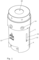
Figure 1 shows a perspective view of a hydraulic tensioner in accordance with an embodiment of the invention; -
Figure 2 shows a vertical cross section through the tensioner ofFigure 1 , through a central plane; and -
Figure 3 shows an exploded perspective view of the tensioner ofFigure 1 . - A
hydraulic tensioner 1 in accordance with an embodiment of the invention is shown in the accompanying drawings. The tension can act to tension and so extend a threaded member of the form of a bolt orstud 2; anut 3 can then be run down thebolt 2 in order to capture that tension. - The tensioner comprises a
base 4, which forms a housing for the tensioner and will rest against a fixed surface. The tensioner also comprises apiston 6, which can move relative tobase 4 alongcentral axis 17 through abore 20. - Between the
base 4 and thepiston 6 there is defined apressure space 13. Hydraulic fluid can be introduced into this space by means of a system ofports 14. By doing so, thepiston 6 can be forced away from thebase 4; thepiston 6 will move alongaxis 17, vertically in the sense of the Figures. - The
piston 6 has a central throughbore 20, coaxial with theaxis 17. In this bore 20 there is provided a thread-engagingmember 7. This thread-engagingmember 7 comprises abody portion 8 of the form of a cylindrical sleeve that fits within thebore 20. The interior of the sleeve defines a threadedbore 30, which engages the threadedmember 2. - The thread-engaging
member 7 has apiston engaging portion 9 positioned at the end of thebody portion 8. It forms a protrusion of the form of a flange, which abuts thepiston 6 such that the force generated by thepiston 6 being urged away from thebase 4 is transmitted to thepiston engaging portion 9, throughbody portion 8 and then through the threaded bore 20 to the threadedmember 2. Thenut 3 can then be run down threadedmember 2 to keep themember 2 in tension and cause thenut 3 to press against the fixed surface once the tension due to the fluid in thepressure space 13 has been released. - However, it is desirable to be able to measure the elongation of the threaded
member 2. In order to be able to do so, asleeve 10 is provided around theexternal surface 5 of thebody portion 8 of the thread-engagingmember 7. Thesleeve 10 is of the form of a cylindrical shell, coaxial with theaxis 17. It is free to rotate relative to the thread-engagingmember 7, but is retained against linear movement along theaxis 17 by a retainingring 27 protruding from theouter surface 5. - This
sleeve 10 carries amagnetic encoder strip 11 along its length, mounted in arecess 21 in the outer surface of thesleeve 10. The magnetic encoder is of the form of a pattern of magnetic poles, so that a pattern of magnetic fields projection axially outwards from thesleeve 10 is created. The length of themagnetic encoder 11 is aligned parallel to theaxis 17. - These magnetic fields can be read by a
magnetic sensor 12 mounted in thebase 4, which will typically be a Hall effect sensor. Themagnetic sensor 12 is fixed relative to thebase 4 by means ofclamps 18. As the threadedmember 2 is extended, themagnetic encoder 11 will move past themagnetic sensor 12; by appropriate processing of the output (through output cable 19) it will be possible to measure the movement of the thread-engagingmember 7 relative to thebase 4 and from that determine the elongation of the threadedmember 2. In the simplest case, the measurement can involve simple counting of the reversals of the magnetic field as poles past, but the skilled man will appreciate that there are multiple ways in which position can be encoded magnetically. - Because the encoder is mounted low down on the
body 8 of the thread-engagingmember 7, fewer errors are introduced into the measurement due to the elastic elongation of parts of thetensioner 1 such as the thread-engaging member. It can be seen that themagnetic encoder 11 is fitted on a portion of thebody portion 8 that is engaging the threaded member, and so by measuring at that point these errors can be minimised. - However, in order to align the
magnetic encoder 11 angularly with themagnetic sensor 12, thesleeve 10 is provided with two protruding pins 15. These are received within correspondingelongate slots 16 in thebase 4, the slots running parallel to theaxis 17. As such, this substantially prevents thesleeve 10 from rotating about theaxis 17 relative to the base 4 (although it can rotate relative to the thread-engaging member 7) whilst allowing the linear movement along the axis that it is desired to measure. - As such, the thread-engaging
member 7 can be screwed onto the threadedmember 2 without having to be concerned about the angular orientation of themagnetic encoder 11 relative to themagnetic sensor 12, as thepins 15 will ensure that that alignment is correct. If the magnetic encoder were directly carried on thebody portion 8 of the thread-engagingmember 7, then it would be necessary to ensure that the thread-engaging member was rotated to the correct position relative to the base on every installation, which would be labour-intensive and prone to inaccuracy. - The output signal from the
magnetic sensor 12 can be read out fromoutput cable 19 and directed to a suitable processor. Whilst the processor, or the processed results, can be located local to thetensioner 1, it is also possible that the raw output signals or the processed results, or any intermediate results, could be transmitted wirelessly to a base station remote from the tensioner. This would be particularly useful where several tensioners were being used together (as such may be used in the bolts securing a wind turbine to the ground, or securing the turbine blades onto the nacelle) and it allows monitoring of several operations simultaneously, and also more flexibly recording the results for traceability's sake. - Whilst the sleeve of this embodiment is fixed rotationally relative to the base, in another embodiment, it is possible to have the sleeve not rotationally fixed, so that the sleeve is free to rotate around the base. In such a case, the encoder would encompass the entire circumferential surface of the sleeve, so that the elongation measurement could be taken regardless of the rotational relationship between the sleeve and the magnetic sensor. In this embodiment, the sleeve would provide the advantage that it the sleeve could be used with multiple different thread-engaging members, rather than requiring each thread-engaging member (or each puller bar) for different sized threads having to be provided with the encoder; thus, only one item needs to be encoded, rather than multiple items.
Claims (11)
- A tensioner (1) for threaded members (2), the tensioner (1) comprising:a base (4) and a piston (6) defining a pressure space (13) therebetween, the base (4) and piston (6) being arranged to be urged apart along an axis (17) upon introduction of a fluid into the pressure space (13); anda thread-engaging member (7), comprising a body portion (8) of the form of a sleeve and having a threaded interior (30) for engagement with a threaded member (2) and a piston engaging portion (9) carrying a protrusion;in which the piston (6) bears against the protrusion such that the piston (6) exerts a force on the protrusion when urged apart from the base (4) by the introduction of fluid into the pressure space (13);characterized in thatthe tensioner (1) further comprises a displacement sensor arranged to determining the relative position of the body portion (8) of the thread-engaging member (7) and the base (4), the displacement sensor comprising a first part (12) carried on the base (4) and a second part (11) carried on the body portion (8).
- The tensioner of claim 1, in which the thread-engaging member (7) comprises a sleeve (10) surrounding the body portion (8), the sleeve (10) carrying the second part (11) of the displacement sensor.
- The tensioner of claim 2, in which the sleeve (10) is free to rotate around the body portion (8), but provided with a stop (27) such that linear movement along the axis (17) relative to the sleeve (10) is restricted.
- The tensioner of claim 3, in which the sleeve (10) is fixed rotationally about the axis (17) relative to the base (4).
- The tensioner of claim 4, in which the sleeve (10) is provided with at least one guide pin (15) protruding from the sleeve (10) and the base (4) has at least one slot (16) formed therein running along the axis (17), each guide pin (15) being received in a corresponding slot (16).
- The tensioner of any of claims 2 to 5, in which the displacement sensor is a linear encoder, in which the second part (11) comprises a scale that encodes a position and the first part (12) is a transducer that reads the scale.
- The tensioner of claim 6, in which the scale is a magnetic encoder, with the scale encoded magnetically and in which the transducer (12) is a magnetic field sensor.
- The tensioner of any preceding claim, in which the displacement sensor is provided with an output (19) for the measured displacement, the output (13) being provided with a wireless transmitter whereby the measured displacement can be transmitted to a remote location.
- The tensioner of any preceding claim, being a hydraulic tensioner comprising a source of pressurised fluid in communication with the pressure space.
- A combination of the tensioner (1) of any preceding claim and a threaded member (2), in which the thread-engaging member (7) is engaged with a thread of the threaded member (2).
- The combination of claim 10, in which the second part (11) of the displacement sensor is positioned axially along the body portion (8) on a portion of the body portion (8) that is engaged with the thread of the threaded member (2).
Applications Claiming Priority (1)
| Application Number | Priority Date | Filing Date | Title |
|---|---|---|---|
| PCT/GB2014/050349 WO2015118283A1 (en) | 2014-02-06 | 2014-02-06 | Tensioner |
Publications (4)
| Publication Number | Publication Date |
|---|---|
| EP3102364A1 EP3102364A1 (en) | 2016-12-14 |
| EP3102364C0 EP3102364C0 (en) | 2024-08-14 |
| EP3102364B1 true EP3102364B1 (en) | 2024-08-14 |
| EP3102364B8 EP3102364B8 (en) | 2024-09-25 |
Family
ID=50277256
Family Applications (1)
| Application Number | Title | Priority Date | Filing Date |
|---|---|---|---|
| EP14710046.5A Active EP3102364B8 (en) | 2014-02-06 | 2014-02-06 | Tensioner |
Country Status (6)
| Country | Link |
|---|---|
| US (1) | US10500685B2 (en) |
| EP (1) | EP3102364B8 (en) |
| CN (1) | CN106102991B (en) |
| ES (1) | ES2994100T3 (en) |
| PL (1) | PL3102364T3 (en) |
| WO (1) | WO2015118283A1 (en) |
Families Citing this family (13)
| Publication number | Priority date | Publication date | Assignee | Title |
|---|---|---|---|---|
| EP3257631A1 (en) * | 2016-05-19 | 2017-12-20 | Actuant Corporation | Tensioning device and method for tensioning a workpiece |
| CN106181888B (en) * | 2016-08-30 | 2018-04-20 | 成都西华升腾科技有限公司 | The bolt tensioner that can be driven over long distances |
| GB2556099A (en) * | 2016-11-21 | 2018-05-23 | Caterpillar Energy Solutions Gmbh | Screw tensioning device |
| GB2579578A (en) * | 2018-12-04 | 2020-07-01 | Tentec Ltd | Hydraulic tensioner and method of tensioning |
| GB2579661A (en) * | 2018-12-11 | 2020-07-01 | Tentec Ltd | Hydraulic tensioning apparatus |
| GB2580111B (en) * | 2018-12-21 | 2021-04-28 | Caterpillar Energy Solutions Gmbh | Device for tensioning a connecting element |
| GB2580102B (en) * | 2018-12-21 | 2021-08-25 | Caterpillar Energy Solutions Gmbh | System for tensioning at least one connecting element |
| WO2020230081A1 (en) * | 2019-05-16 | 2020-11-19 | Advmet (Pty) Ltd | A mechanical tensioning system and method |
| WO2020230082A1 (en) * | 2019-05-16 | 2020-11-19 | Advmet (Pty) Ltd | A mechanical tensioning device and method |
| EP4126459A1 (en) | 2020-03-25 | 2023-02-08 | Milwaukee Electric Tool Corporation | Bolt tensioning tool |
| CN113441940B (en) * | 2021-06-30 | 2022-09-27 | 哈尔滨工业大学 | Piezoelectric transducer pre-tightening assembly device and method loaded along axial direction of bolt |
| USD1125286S1 (en) * | 2021-07-12 | 2026-05-05 | Atlas Copco Industrial Technique Ab | Bolt tensioner |
| CN121514882B (en) * | 2026-01-14 | 2026-04-10 | 宁波竤远船舶动力设备有限公司 | Marine cylinder head stretcher |
Family Cites Families (24)
| Publication number | Priority date | Publication date | Assignee | Title |
|---|---|---|---|---|
| US3722332A (en) * | 1971-06-01 | 1973-03-27 | Transfer Systems | Apparatus for securing the bolts of the reactor pressure vessel head to the reactor pressure vessel |
| DE2455788A1 (en) | 1974-11-26 | 1976-08-12 | Horst Schenk | Hydraulic tensioner for large tie rods - uses metal sealing rings to apply very high hydraulic pressure |
| US3995828A (en) * | 1975-09-16 | 1976-12-07 | Biach Industries, Inc. | Bolt tensioning apparatus |
| US4535656A (en) * | 1981-03-12 | 1985-08-20 | Orban Joseph N | Integral tensioner assembly for tensioning, inserting and removing a stud |
| FR2615776B1 (en) * | 1987-05-27 | 1989-09-22 | Framatome Sa | DEVICE FOR SCREWING AND UNSCREWING LARGE DOWELS OR BOLTS |
| US4914389A (en) * | 1988-10-24 | 1990-04-03 | Eaton Corporation | Multiturn shaft position sensor with backlash compensation |
| JPH03204406A (en) | 1990-01-08 | 1991-09-06 | Hitachi Ltd | Bolt tensioning device and method |
| US5398574A (en) * | 1992-12-23 | 1995-03-21 | Unex Corporation | Fluid operating tool |
| DE4313778A1 (en) * | 1993-04-27 | 1994-11-03 | Westfalia Becorit Ind Tech | Screw clamping device |
| US5842263A (en) * | 1996-01-11 | 1998-12-01 | Westinghouse Electric Corporation | Method and manufacture of an axial tensioned bolt |
| US6851324B2 (en) * | 2002-12-16 | 2005-02-08 | Delphi Technologies, Inc. | Non-contacting compliant torque sensor |
| US20040129118A1 (en) * | 2003-01-02 | 2004-07-08 | Junkers John K. | Fluid-operated torque tool |
| FR2905460B1 (en) * | 2006-09-01 | 2009-08-07 | Skf Ab | METHOD AND DEVICE FOR CONTROLLING HYDRAULIC CLAMPING OF ONE OR MORE BOLTS. |
| NL1033069C2 (en) * | 2006-12-15 | 2008-06-17 | Ind Bolting Technology And Sup | Device and method for tightening a nut turned on a threaded end and composite washer and nut for such a device. |
| GB0720972D0 (en) * | 2007-10-25 | 2007-12-05 | Renishaw Plc | Magnetic encoder |
| EP2361722B1 (en) * | 2010-02-18 | 2013-01-16 | Aktiebolaget SKF | Rod tensioning device. |
| DE102011075807A1 (en) | 2011-05-13 | 2012-11-15 | Amtec Advanced Measurement Messtechnischer Service Gmbh | Device for the controlled bracing of flange connections |
| CN102497088B (en) * | 2011-12-15 | 2014-06-25 | 矽力杰半导体技术(杭州)有限公司 | Adaptive series circuit with metal oxide semiconductor (MOS) transistors |
| FI124931B (en) * | 2012-02-09 | 2015-03-31 | Wärtsilä Finland Oy | Pre-tensioning tool and method for tightening a nut |
| DE102012102855A1 (en) * | 2012-04-02 | 2013-10-02 | Asg Luftfahrttechnik Und Sensorik Gmbh | Method and arrangement for determining the position of a component and sensor |
| US9035647B2 (en) * | 2012-07-02 | 2015-05-19 | Leine & Linde Ab | Encoder |
| DE102012106503B4 (en) * | 2012-07-18 | 2023-03-16 | Jörg Hohmann | Clamping device for stretching a threaded bolt |
| US9375959B2 (en) * | 2012-08-29 | 2016-06-28 | Hewlett-Packard Development Company, L.P. | Locking mechanism for an encoder strip |
| DE102014106215A1 (en) * | 2014-05-05 | 2015-11-05 | Frank Hohmann | Clamping device for stretching a threaded bolt |
-
2014
- 2014-02-06 US US15/116,988 patent/US10500685B2/en active Active
- 2014-02-06 WO PCT/GB2014/050349 patent/WO2015118283A1/en not_active Ceased
- 2014-02-06 PL PL14710046.5T patent/PL3102364T3/en unknown
- 2014-02-06 EP EP14710046.5A patent/EP3102364B8/en active Active
- 2014-02-06 CN CN201480074956.4A patent/CN106102991B/en active Active
- 2014-02-06 ES ES14710046T patent/ES2994100T3/en active Active
Also Published As
| Publication number | Publication date |
|---|---|
| EP3102364C0 (en) | 2024-08-14 |
| US10500685B2 (en) | 2019-12-10 |
| US20170203397A1 (en) | 2017-07-20 |
| PL3102364T3 (en) | 2025-02-17 |
| CN106102991B (en) | 2020-04-24 |
| CN106102991A (en) | 2016-11-09 |
| EP3102364A1 (en) | 2016-12-14 |
| WO2015118283A1 (en) | 2015-08-13 |
| ES2994100T3 (en) | 2025-01-17 |
| EP3102364B8 (en) | 2024-09-25 |
Similar Documents
| Publication | Publication Date | Title |
|---|---|---|
| US10500685B2 (en) | Tensioner | |
| US20190331552A1 (en) | Conveyor and components therefor, monitoring methods and communication systems | |
| US8646339B2 (en) | Thread clamping device including internal sensing and reporting | |
| Pan et al. | A vision-based monitoring method for the looseness of high-strength bolt | |
| EP3894138B1 (en) | Hydraulic tensioning apparatus | |
| US8831907B2 (en) | Angular position encoder for a rotating shaft | |
| US20210355766A1 (en) | Riser tools and methods | |
| DE112013007631T5 (en) | Device and method of bearing control | |
| SE1750050A1 (en) | Deformation measurement method and apparatus | |
| EP3164686A1 (en) | Sensing device | |
| US9140530B2 (en) | Method and device for inspecting a threading of a tubular connection used in the oil industry | |
| US20220349462A1 (en) | Slew drive systems and methods of use thereof | |
| US20240011946A1 (en) | Ultrasonic Sensor Arrangement | |
| US20200080416A1 (en) | Fatigue Monitoring Of Coiled Tubing In Downline Deployments | |
| EP2270452A3 (en) | Device for temperature monitoring in electrical assemblies, electrical assembly with such a device and method for operating same | |
| EP3100008B1 (en) | A method and apparatus for a structural monitoring device adapted to be locatable within a tubular structure | |
| GB2527864A (en) | Sensing device | |
| US20230141264A1 (en) | Bolt transducer | |
| CN202903737U (en) | Portable steel wire rope damage detection device | |
| EP2196829A3 (en) | Location device | |
| CN107153183B (en) | Vehicle-mounted laser range finder | |
| CN109059830A (en) | A kind of bolt elongate amount detecting device | |
| CN206399394U (en) | A kind of accurate steel ruler convergence device | |
| CN102607372A (en) | Piston skirt detecting device | |
| CN214533063U (en) | Freezing wall of a well pressure sensor fixing device |
Legal Events
| Date | Code | Title | Description |
|---|---|---|---|
| PUAI | Public reference made under article 153(3) epc to a published international application that has entered the european phase |
Free format text: ORIGINAL CODE: 0009012 |
|
| STAA | Information on the status of an ep patent application or granted ep patent |
Free format text: STATUS: REQUEST FOR EXAMINATION WAS MADE |
|
| 17P | Request for examination filed |
Effective date: 20160812 |
|
| AK | Designated contracting states |
Kind code of ref document: A1 Designated state(s): AL AT BE BG CH CY CZ DE DK EE ES FI FR GB GR HR HU IE IS IT LI LT LU LV MC MK MT NL NO PL PT RO RS SE SI SK SM TR |
|
| AX | Request for extension of the european patent |
Extension state: BA ME |
|
| DAX | Request for extension of the european patent (deleted) | ||
| STAA | Information on the status of an ep patent application or granted ep patent |
Free format text: STATUS: EXAMINATION IS IN PROGRESS |
|
| 17Q | First examination report despatched |
Effective date: 20211104 |
|
| GRAP | Despatch of communication of intention to grant a patent |
Free format text: ORIGINAL CODE: EPIDOSNIGR1 |
|
| STAA | Information on the status of an ep patent application or granted ep patent |
Free format text: STATUS: GRANT OF PATENT IS INTENDED |
|
| INTG | Intention to grant announced |
Effective date: 20240311 |
|
| GRAS | Grant fee paid |
Free format text: ORIGINAL CODE: EPIDOSNIGR3 |
|
| GRAA | (expected) grant |
Free format text: ORIGINAL CODE: 0009210 |
|
| STAA | Information on the status of an ep patent application or granted ep patent |
Free format text: STATUS: THE PATENT HAS BEEN GRANTED |
|
| AK | Designated contracting states |
Kind code of ref document: B1 Designated state(s): AL AT BE BG CH CY CZ DE DK EE ES FI FR GB GR HR HU IE IS IT LI LT LU LV MC MK MT NL NO PL PT RO RS SE SI SK SM TR |
|
| REG | Reference to a national code |
Ref country code: GB Ref legal event code: FG4D |
|
| REG | Reference to a national code |
Ref country code: CH Ref legal event code: EP |
|
| REG | Reference to a national code |
Ref country code: DE Ref legal event code: R081 Ref document number: 602014090688 Country of ref document: DE Owner name: TENTEC LTD., GB Free format text: FORMER OWNER: TENTEC LTD., WEST BROMWICH, GB |
|
| REG | Reference to a national code |
Ref country code: CH Ref legal event code: PK Free format text: BERICHTIGUNG B8 |
|
| REG | Reference to a national code |
Ref country code: DE Ref legal event code: R096 Ref document number: 602014090688 Country of ref document: DE |
|
| RAP4 | Party data changed (patent owner data changed or rights of a patent transferred) |
Owner name: TENTEC LIMITED |
|
| REG | Reference to a national code |
Ref country code: IE Ref legal event code: FG4D |
|
| U01 | Request for unitary effect filed |
Effective date: 20240906 |
|
| U07 | Unitary effect registered |
Designated state(s): AT BE BG DE DK EE FI FR IT LT LU LV MT NL PT RO SE SI Effective date: 20240924 |
|
| U20 | Renewal fee for the european patent with unitary effect paid |
Year of fee payment: 12 Effective date: 20241203 |
|
| PG25 | Lapsed in a contracting state [announced via postgrant information from national office to epo] |
Ref country code: NO Free format text: LAPSE BECAUSE OF FAILURE TO SUBMIT A TRANSLATION OF THE DESCRIPTION OR TO PAY THE FEE WITHIN THE PRESCRIBED TIME-LIMIT Effective date: 20241114 |
|
| PG25 | Lapsed in a contracting state [announced via postgrant information from national office to epo] |
Ref country code: GR Free format text: LAPSE BECAUSE OF FAILURE TO SUBMIT A TRANSLATION OF THE DESCRIPTION OR TO PAY THE FEE WITHIN THE PRESCRIBED TIME-LIMIT Effective date: 20241115 |
|
| REG | Reference to a national code |
Ref country code: ES Ref legal event code: FG2A Ref document number: 2994100 Country of ref document: ES Kind code of ref document: T3 Effective date: 20250117 |
|
| PG25 | Lapsed in a contracting state [announced via postgrant information from national office to epo] |
Ref country code: IS Free format text: LAPSE BECAUSE OF FAILURE TO SUBMIT A TRANSLATION OF THE DESCRIPTION OR TO PAY THE FEE WITHIN THE PRESCRIBED TIME-LIMIT Effective date: 20241214 |
|
| PG25 | Lapsed in a contracting state [announced via postgrant information from national office to epo] |
Ref country code: HR Free format text: LAPSE BECAUSE OF FAILURE TO SUBMIT A TRANSLATION OF THE DESCRIPTION OR TO PAY THE FEE WITHIN THE PRESCRIBED TIME-LIMIT Effective date: 20240814 |
|
| PG25 | Lapsed in a contracting state [announced via postgrant information from national office to epo] |
Ref country code: RS Free format text: LAPSE BECAUSE OF FAILURE TO SUBMIT A TRANSLATION OF THE DESCRIPTION OR TO PAY THE FEE WITHIN THE PRESCRIBED TIME-LIMIT Effective date: 20241114 |
|
| PG25 | Lapsed in a contracting state [announced via postgrant information from national office to epo] |
Ref country code: RS Free format text: LAPSE BECAUSE OF FAILURE TO SUBMIT A TRANSLATION OF THE DESCRIPTION OR TO PAY THE FEE WITHIN THE PRESCRIBED TIME-LIMIT Effective date: 20241114 Ref country code: NO Free format text: LAPSE BECAUSE OF FAILURE TO SUBMIT A TRANSLATION OF THE DESCRIPTION OR TO PAY THE FEE WITHIN THE PRESCRIBED TIME-LIMIT Effective date: 20241114 Ref country code: IS Free format text: LAPSE BECAUSE OF FAILURE TO SUBMIT A TRANSLATION OF THE DESCRIPTION OR TO PAY THE FEE WITHIN THE PRESCRIBED TIME-LIMIT Effective date: 20241214 Ref country code: HR Free format text: LAPSE BECAUSE OF FAILURE TO SUBMIT A TRANSLATION OF THE DESCRIPTION OR TO PAY THE FEE WITHIN THE PRESCRIBED TIME-LIMIT Effective date: 20240814 Ref country code: GR Free format text: LAPSE BECAUSE OF FAILURE TO SUBMIT A TRANSLATION OF THE DESCRIPTION OR TO PAY THE FEE WITHIN THE PRESCRIBED TIME-LIMIT Effective date: 20241115 |
|
| PG25 | Lapsed in a contracting state [announced via postgrant information from national office to epo] |
Ref country code: SM Free format text: LAPSE BECAUSE OF FAILURE TO SUBMIT A TRANSLATION OF THE DESCRIPTION OR TO PAY THE FEE WITHIN THE PRESCRIBED TIME-LIMIT Effective date: 20240814 |
|
| PG25 | Lapsed in a contracting state [announced via postgrant information from national office to epo] |
Ref country code: CZ Free format text: LAPSE BECAUSE OF FAILURE TO SUBMIT A TRANSLATION OF THE DESCRIPTION OR TO PAY THE FEE WITHIN THE PRESCRIBED TIME-LIMIT Effective date: 20240814 |
|
| PG25 | Lapsed in a contracting state [announced via postgrant information from national office to epo] |
Ref country code: SK Free format text: LAPSE BECAUSE OF FAILURE TO SUBMIT A TRANSLATION OF THE DESCRIPTION OR TO PAY THE FEE WITHIN THE PRESCRIBED TIME-LIMIT Effective date: 20240814 |
|
| PLBE | No opposition filed within time limit |
Free format text: ORIGINAL CODE: 0009261 |
|
| STAA | Information on the status of an ep patent application or granted ep patent |
Free format text: STATUS: NO OPPOSITION FILED WITHIN TIME LIMIT |
|
| 26N | No opposition filed |
Effective date: 20250515 |
|
| PG25 | Lapsed in a contracting state [announced via postgrant information from national office to epo] |
Ref country code: MC Free format text: LAPSE BECAUSE OF FAILURE TO SUBMIT A TRANSLATION OF THE DESCRIPTION OR TO PAY THE FEE WITHIN THE PRESCRIBED TIME-LIMIT Effective date: 20240814 |
|
| REG | Reference to a national code |
Ref country code: CH Ref legal event code: PL |
|
| PG25 | Lapsed in a contracting state [announced via postgrant information from national office to epo] |
Ref country code: CH Free format text: LAPSE BECAUSE OF NON-PAYMENT OF DUE FEES Effective date: 20250228 |
|
| U20 | Renewal fee for the european patent with unitary effect paid |
Year of fee payment: 13 Effective date: 20251203 |
|
| PGFP | Annual fee paid to national office [announced via postgrant information from national office to epo] |
Ref country code: GB Payment date: 20251202 Year of fee payment: 13 |
|
| PG25 | Lapsed in a contracting state [announced via postgrant information from national office to epo] |
Ref country code: IE Free format text: LAPSE BECAUSE OF NON-PAYMENT OF DUE FEES Effective date: 20250206 |
|
| PGFP | Annual fee paid to national office [announced via postgrant information from national office to epo] |
Ref country code: ES Payment date: 20260317 Year of fee payment: 13 |
|
| PGFP | Annual fee paid to national office [announced via postgrant information from national office to epo] |
Ref country code: PL Payment date: 20260114 Year of fee payment: 13 |