EP3102004A1 - Lighting device and frame with said lighting device attached thereto - Google Patents
Lighting device and frame with said lighting device attached thereto Download PDFInfo
- Publication number
- EP3102004A1 EP3102004A1 EP14873521.0A EP14873521A EP3102004A1 EP 3102004 A1 EP3102004 A1 EP 3102004A1 EP 14873521 A EP14873521 A EP 14873521A EP 3102004 A1 EP3102004 A1 EP 3102004A1
- Authority
- EP
- European Patent Office
- Prior art keywords
- illumination
- time
- lamp
- musical piece
- predetermined period
- Prior art date
- Legal status (The legal status is an assumption and is not a legal conclusion. Google has not performed a legal analysis and makes no representation as to the accuracy of the status listed.)
- Granted
Links
- 238000005286 illumination Methods 0.000 claims abstract description 137
- 238000000605 extraction Methods 0.000 claims abstract description 35
- 238000001514 detection method Methods 0.000 claims abstract description 31
- 230000005236 sound signal Effects 0.000 claims abstract description 29
- 230000004044 response Effects 0.000 claims abstract description 13
- 230000005540 biological transmission Effects 0.000 claims description 11
- 238000006243 chemical reaction Methods 0.000 claims description 4
- 239000003086 colorant Substances 0.000 claims description 2
- 238000010422 painting Methods 0.000 abstract description 46
- 238000000034 method Methods 0.000 description 18
- 230000008569 process Effects 0.000 description 18
- 230000008859 change Effects 0.000 description 15
- 230000006870 function Effects 0.000 description 11
- 239000003973 paint Substances 0.000 description 10
- FFBHFFJDDLITSX-UHFFFAOYSA-N benzyl N-[2-hydroxy-4-(3-oxomorpholin-4-yl)phenyl]carbamate Chemical compound OC1=C(NC(=O)OCC2=CC=CC=C2)C=CC(=C1)N1CCOCC1=O FFBHFFJDDLITSX-UHFFFAOYSA-N 0.000 description 5
- 241000282414 Homo sapiens Species 0.000 description 3
- 230000000903 blocking effect Effects 0.000 description 3
- 238000010586 diagram Methods 0.000 description 3
- 230000000694 effects Effects 0.000 description 3
- 238000004891 communication Methods 0.000 description 2
- 238000012986 modification Methods 0.000 description 2
- 230000004048 modification Effects 0.000 description 2
- 230000002123 temporal effect Effects 0.000 description 2
- 241001133760 Acoelorraphe Species 0.000 description 1
- PEDCQBHIVMGVHV-UHFFFAOYSA-N Glycerine Chemical compound OCC(O)CO PEDCQBHIVMGVHV-UHFFFAOYSA-N 0.000 description 1
- 230000007613 environmental effect Effects 0.000 description 1
- 239000000284 extract Substances 0.000 description 1
- 239000002184 metal Substances 0.000 description 1
- 229920003002 synthetic resin Polymers 0.000 description 1
- 239000000057 synthetic resin Substances 0.000 description 1
Images


Classifications
-
- H—ELECTRICITY
- H05—ELECTRIC TECHNIQUES NOT OTHERWISE PROVIDED FOR
- H05B—ELECTRIC HEATING; ELECTRIC LIGHT SOURCES NOT OTHERWISE PROVIDED FOR; CIRCUIT ARRANGEMENTS FOR ELECTRIC LIGHT SOURCES, IN GENERAL
- H05B47/00—Circuit arrangements for operating light sources in general, i.e. where the type of light source is not relevant
- H05B47/10—Controlling the light source
- H05B47/105—Controlling the light source in response to determined parameters
- H05B47/115—Controlling the light source in response to determined parameters by determining the presence or movement of objects or living beings
- H05B47/12—Controlling the light source in response to determined parameters by determining the presence or movement of objects or living beings by detecting audible sound
-
- F—MECHANICAL ENGINEERING; LIGHTING; HEATING; WEAPONS; BLASTING
- F21—LIGHTING
- F21V—FUNCTIONAL FEATURES OR DETAILS OF LIGHTING DEVICES OR SYSTEMS THEREOF; STRUCTURAL COMBINATIONS OF LIGHTING DEVICES WITH OTHER ARTICLES, NOT OTHERWISE PROVIDED FOR
- F21V33/00—Structural combinations of lighting devices with other articles, not otherwise provided for
- F21V33/0004—Personal or domestic articles
- F21V33/0024—Household or table equipment
- F21V33/0028—Decorative household equipment, e.g. plant holders or food dummies
- F21V33/0032—Paintings, pictures or photographs; Frames therefor
-
- A—HUMAN NECESSITIES
- A47—FURNITURE; DOMESTIC ARTICLES OR APPLIANCES; COFFEE MILLS; SPICE MILLS; SUCTION CLEANERS IN GENERAL
- A47G—HOUSEHOLD OR TABLE EQUIPMENT
- A47G1/00—Mirrors; Picture frames or the like, e.g. provided with heating, lighting or ventilating means
- A47G1/06—Picture frames
- A47G1/0616—Ornamental frames, e.g. with illumination, speakers or decorative features
- A47G1/0622—Ornamental frames, e.g. with illumination, speakers or decorative features with illumination
-
- G—PHYSICS
- G10—MUSICAL INSTRUMENTS; ACOUSTICS
- G10L—SPEECH ANALYSIS OR SYNTHESIS; SPEECH RECOGNITION; SPEECH OR VOICE PROCESSING; SPEECH OR AUDIO CODING OR DECODING
- G10L25/00—Speech or voice analysis techniques not restricted to a single one of groups G10L15/00 - G10L21/00
- G10L25/03—Speech or voice analysis techniques not restricted to a single one of groups G10L15/00 - G10L21/00 characterised by the type of extracted parameters
- G10L25/18—Speech or voice analysis techniques not restricted to a single one of groups G10L15/00 - G10L21/00 characterised by the type of extracted parameters the extracted parameters being spectral information of each sub-band
-
- H—ELECTRICITY
- H05—ELECTRIC TECHNIQUES NOT OTHERWISE PROVIDED FOR
- H05B—ELECTRIC HEATING; ELECTRIC LIGHT SOURCES NOT OTHERWISE PROVIDED FOR; CIRCUIT ARRANGEMENTS FOR ELECTRIC LIGHT SOURCES, IN GENERAL
- H05B47/00—Circuit arrangements for operating light sources in general, i.e. where the type of light source is not relevant
- H05B47/10—Controlling the light source
- H05B47/155—Coordinated control of two or more light sources
-
- F—MECHANICAL ENGINEERING; LIGHTING; HEATING; WEAPONS; BLASTING
- F21—LIGHTING
- F21W—INDEXING SCHEME ASSOCIATED WITH SUBCLASSES F21K, F21L, F21S and F21V, RELATING TO USES OR APPLICATIONS OF LIGHTING DEVICES OR SYSTEMS
- F21W2131/00—Use or application of lighting devices or systems not provided for in codes F21W2102/00-F21W2121/00
- F21W2131/30—Lighting for domestic or personal use
- F21W2131/304—Lighting for domestic or personal use for pictures
-
- G—PHYSICS
- G10—MUSICAL INSTRUMENTS; ACOUSTICS
- G10H—ELECTROPHONIC MUSICAL INSTRUMENTS; INSTRUMENTS IN WHICH THE TONES ARE GENERATED BY ELECTROMECHANICAL MEANS OR ELECTRONIC GENERATORS, OR IN WHICH THE TONES ARE SYNTHESISED FROM A DATA STORE
- G10H2210/00—Aspects or methods of musical processing having intrinsic musical character, i.e. involving musical theory or musical parameters or relying on musical knowledge, as applied in electrophonic musical tools or instruments
- G10H2210/031—Musical analysis, i.e. isolation, extraction or identification of musical elements or musical parameters from a raw acoustic signal or from an encoded audio signal
- G10H2210/046—Musical analysis, i.e. isolation, extraction or identification of musical elements or musical parameters from a raw acoustic signal or from an encoded audio signal for differentiation between music and non-music signals, based on the identification of musical parameters, e.g. based on tempo detection
-
- G—PHYSICS
- G10—MUSICAL INSTRUMENTS; ACOUSTICS
- G10H—ELECTROPHONIC MUSICAL INSTRUMENTS; INSTRUMENTS IN WHICH THE TONES ARE GENERATED BY ELECTROMECHANICAL MEANS OR ELECTRONIC GENERATORS, OR IN WHICH THE TONES ARE SYNTHESISED FROM A DATA STORE
- G10H2210/00—Aspects or methods of musical processing having intrinsic musical character, i.e. involving musical theory or musical parameters or relying on musical knowledge, as applied in electrophonic musical tools or instruments
- G10H2210/031—Musical analysis, i.e. isolation, extraction or identification of musical elements or musical parameters from a raw acoustic signal or from an encoded audio signal
- G10H2210/051—Musical analysis, i.e. isolation, extraction or identification of musical elements or musical parameters from a raw acoustic signal or from an encoded audio signal for extraction or detection of onsets of musical sounds or notes, i.e. note attack timings
-
- G—PHYSICS
- G10—MUSICAL INSTRUMENTS; ACOUSTICS
- G10H—ELECTROPHONIC MUSICAL INSTRUMENTS; INSTRUMENTS IN WHICH THE TONES ARE GENERATED BY ELECTROMECHANICAL MEANS OR ELECTRONIC GENERATORS, OR IN WHICH THE TONES ARE SYNTHESISED FROM A DATA STORE
- G10H2220/00—Input/output interfacing specifically adapted for electrophonic musical tools or instruments
- G10H2220/005—Non-interactive screen display of musical or status data
-
- G—PHYSICS
- G10—MUSICAL INSTRUMENTS; ACOUSTICS
- G10H—ELECTROPHONIC MUSICAL INSTRUMENTS; INSTRUMENTS IN WHICH THE TONES ARE GENERATED BY ELECTROMECHANICAL MEANS OR ELECTRONIC GENERATORS, OR IN WHICH THE TONES ARE SYNTHESISED FROM A DATA STORE
- G10H2220/00—Input/output interfacing specifically adapted for electrophonic musical tools or instruments
- G10H2220/155—User input interfaces for electrophonic musical instruments
- G10H2220/405—Beam sensing or control, i.e. input interfaces involving substantially immaterial beams, radiation, or fields of any nature, used, e.g. as a switch as in a light barrier, or as a control device, e.g. using the theremin electric field sensing principle
- G10H2220/411—Light beams
-
- G—PHYSICS
- G10—MUSICAL INSTRUMENTS; ACOUSTICS
- G10H—ELECTROPHONIC MUSICAL INSTRUMENTS; INSTRUMENTS IN WHICH THE TONES ARE GENERATED BY ELECTROMECHANICAL MEANS OR ELECTRONIC GENERATORS, OR IN WHICH THE TONES ARE SYNTHESISED FROM A DATA STORE
- G10H2250/00—Aspects of algorithms or signal processing methods without intrinsic musical character, yet specifically adapted for or used in electrophonic musical processing
- G10H2250/131—Mathematical functions for musical analysis, processing, synthesis or composition
- G10H2250/215—Transforms, i.e. mathematical transforms into domains appropriate for musical signal processing, coding or compression
- G10H2250/235—Fourier transform; Discrete Fourier Transform [DFT]; Fast Fourier Transform [FFT]
-
- G—PHYSICS
- G10—MUSICAL INSTRUMENTS; ACOUSTICS
- G10L—SPEECH ANALYSIS OR SYNTHESIS; SPEECH RECOGNITION; SPEECH OR VOICE PROCESSING; SPEECH OR AUDIO CODING OR DECODING
- G10L25/00—Speech or voice analysis techniques not restricted to a single one of groups G10L15/00 - G10L21/00
- G10L25/78—Detection of presence or absence of voice signals
-
- Y—GENERAL TAGGING OF NEW TECHNOLOGICAL DEVELOPMENTS; GENERAL TAGGING OF CROSS-SECTIONAL TECHNOLOGIES SPANNING OVER SEVERAL SECTIONS OF THE IPC; TECHNICAL SUBJECTS COVERED BY FORMER USPC CROSS-REFERENCE ART COLLECTIONS [XRACs] AND DIGESTS
- Y02—TECHNOLOGIES OR APPLICATIONS FOR MITIGATION OR ADAPTATION AGAINST CLIMATE CHANGE
- Y02B—CLIMATE CHANGE MITIGATION TECHNOLOGIES RELATED TO BUILDINGS, e.g. HOUSING, HOUSE APPLIANCES OR RELATED END-USER APPLICATIONS
- Y02B20/00—Energy efficient lighting technologies, e.g. halogen lamps or gas discharge lamps
- Y02B20/40—Control techniques providing energy savings, e.g. smart controller or presence detection
Definitions
- the present invention relates to a technical field of an illumination device used to irradiate a painting, a poster or a copy thereof (hereinafter referred to as a painting or the like), and a technical field of a frame which is provided with such an illumination device.
- illumination devices for illuminating a painting or the like expressing at the same time a daytime scenery and a nighttime scenery by using a special paint which is caused by ultraviolet rays to emit or reflect light
- Patent Literature 1 for example.
- this type of illumination device due consideration is given to ensure that the difference between a daytime scenery and a nighttime scenery is fully expressed.
- this type of illumination device allows viewing of a painting or the like in a state according to a gradual change in the nature from a daytime scenery to a nighttime scenery, and allows a viewer of the painting or the like to feel the sense of ambience.
- Patent Literature 1 JP 2880476 B1
- Patent Literature 1 Although the illumination device disclosed in Patent Literature 1 is able to meet the demand of viewers who want to enjoy viewing a painting or the like in a state according to a change in the nature, it cannot meet the demand of viewers who want to enjoy viewing a painting or the like while listening to a musical piece, with sound providing a great sense of ambience.
- the present invention has its aim to provide an illumination device that can fully meet the demand of viewers who want to enjoy viewing paintings or the like with sound providing a great sense of ambience, and a frame provided with the illumination device.
- the second illumination lamp which is capable of radiating white light, repeats a predetermined control pattern of increasing and reducing the illuminance over time, and the first illumination lamp, which is capable of radiating ultraviolet rays, is turned off during a predetermined period of time when the second illumination lamp is turned on. Accordingly, by being used on a painting or the like which is partially painted with special paint that emits light or reflects ultraviolet rays when irradiated with ultraviolet rays, the illumination device may allow a viewer to perceive a change in the expression of the painting or the like with a great sense of ambience and a great sense of surprise, and may thus offer the viewer deep relaxation.
- the illumination control unit causes the first and the second illumination lamps to be turned on in response to detection of the start of performance by the performance state detection unit, and causes the first and the second illumination lamps to be turned off in response to detection of the end of performance by the performance state detection unit, and thus the past demand of viewers who wanted to enjoy viewing a painting or the like while listening to a musical piece, with sound providing a great sense of ambience, may be fully met. Accordingly, viewers may experience even deeper relaxation by listening to a musical piece while viewing a painting or the like.
- the illumination device of the present invention and the frame provided with the illumination device, the demand of viewers who want to enjoy viewing a painting or the like while listening to a musical piece, with sound providing a great sense of ambience, may be fully met. Accordingly, viewers may experience deep relaxation by listening to a musical piece while viewing a painting or the like.
- an illumination device 1 is used by being attached to a frame F holding a painting P which is partially drawn with special paint that emits light by ultraviolet rays or that reflects ultraviolet rays.
- the painting P shown in the present embodiment depicts a scenery of a beach, and the sun, the mountain, the sea, the palm trees and the like are drawn with ordinary paint that is conventionally used, and a crescent moon-shaped figure P2 is drawn with special paint inside a circular figure P1 indicating the sun.
- P3 indicating light of a light house and a figure P4 which is a reflection of the moonlight from the crescent moon on the surface of the sea are drawn with the special paint.
- each of the figures P2, P3, and P4 drawn with special paint is shown in Fig. 1 by broken lines.
- the illumination device 1 includes a device main body 2 that is mounted and fixed on the top surface of the frame F, a first arm 3 whose base end is fixed to the left side of the device main body 2, a second arm 4 whose base end is fixed to the right side of the device main body 2, and an illumination unit 5 that is rotatably supported by the tip ends of the first and the second arms 3, 4.
- a control circuit 23 serving as an illumination control unit for turning on or off first and second illumination lamps described later is built into the device main body 2. Also, as shown in Fig. 1 , the first and the second arms 3, 4 are each formed to have an arc shape and are hollow inside, and lead wires, not shown, are disposed inside the hollow first and second arms 3, 4. Additionally, the lead wires electrically connect the control circuit 23 (see Fig. 4 ) and an ultraviolet lamp (blacklight) 15 (see Fig. 3 ) serving as a first illumination lamp and a first incandescent lamp 16 to a fourth incandescent lamp 19 (see Fig. 3 ) serving as second illumination lamps, the lamps being disposed inside the illumination unit 5.
- an ultraviolet lamp (blacklight) 15 serving as a first illumination lamp and a first incandescent lamp 16
- a fourth incandescent lamp 19 serving as second illumination lamps
- the illumination unit 5 attached to tip end portions of the first and the second arms 3, 4 includes a lampshade 6 having two arc-shaped parts 6a, 6b of integrally formed metal or synthetic resin, for example.
- a long and narrow front-side attachment member 8 which is fixed on the inner forward surface of the lampshade 6 by a screw 7
- a long and narrow rear-side attachment member 9 which is fixed on the inner rearward surface of the lampshade 6 by a screw 7 and which is parallel to the front-side attachment member 8.
- Fig. 1 the illumination unit 5 attached to tip end portions of the first and the second arms 3, 4 includes a lampshade 6 having two arc-shaped parts 6a, 6b of integrally formed metal or synthetic resin, for example.
- a long and narrow front-side attachment member 8 which is fixed on the inner forward surface of the lampshade 6 by a screw 7
- a long and narrow rear-side attachment member 9 which is fixed on the inner rearward surface of the lampshade 6 by a screw 7 and which is parallel to the front-
- left and right blocking plates 11, 12 are fixed to the left and right end sides of the front-side attachment member 8 and the rear-side attachment member 9 by screws 10.
- a pair of connectors 13, 14 including connection terminals is fixed on the back side of the left and right blocking plates 11, 12.
- the ultraviolet lamp 15 serving as the first illumination lamp is attached to the connectors 13, 14 in a detachable/attachable manner.
- the first incandescent lamp 16 to the fourth incandescent lamp 19 are linearly attached on the rear side surface of the front-side attachment member 8.
- the ultraviolet lamp 15 and the incandescent lamps 16 to 19 of the illumination device 1 are controlled by the control circuit built into the device main body 2.
- the control circuit includes a CPU (Central Processing Unit) 23, and operating power is supplied thereto by a power supply circuit 22 to which power is supplied by a commercial power supply 20 via a main switch 21.
- the CPU 23 includes a storage unit, which is a storage device (memory), as described later, and is connected to the incandescent lamps 16 to 19 by a first driver circuit 24 to a fourth driver circuit 27, respectively.
- the ultraviolet lamp 15 is connected to the commercial power supply 20 via the main switch 21 and a switching element 30. The switching element 30 is controlled by the CPU 23.
- a remote control receiver unit 28 serving as a reception device is connected to the CPU 23.
- the remote control receiver unit 28 receives operation signals issued by a remote control transmitter unit 29 serving as a transmission device, and supplies the signals to the CPU 23.
- the CPU 23 is configured to enable various settings described later according to the operation signals.
- a signal reception unit 50 is connected to the CPU 23.
- the signal reception unit 50 receives an analog audio signal, which is a musical piece with noises added thereto, from outside via a microphone (not shown), converts the signal into a digital audio signal, and supplies the digital audio signal to the CPU 23.
- each of the incandescent lamps 16 to 19 is controlled by the CPU 23 and the corresponding one of the driver circuits 24 to 27 to repeat turning on and off (see the graphs in Figs. 8 (a) to 8(c) ).
- each of the driver circuits 24 to 27 is configured from an NPN control transistor 24a whose base terminal is connected to the CPU 23, and a PNP driver transistor 24b whose base terminal is connected to a collector terminal of the control transistor 24a. An emitter terminal of the control transistor 24a is grounded. Also, a power supply voltage Ve is supplied to an emitter terminal of the driver transistor 24b.
- each of the incandescent lamps 16 to 19 has its positive terminal connected to a collector terminal of the driver transistor 24b and its negative terminal grounded.
- the CPU 23 is provided with a storage unit (not shown) serving as a storage device (memory).
- a storage unit (not shown) serving as a storage device (memory).
- the illuminance values of the ultraviolet lamp 15 and the incandescent lamps 16 to 19 responsive to temporal changes, that is, the control patterns are stored in advance in the storage unit as first to third control patterns.
- a first switch 31 to a third switch 33 are provided to the remote control transmitter unit 29. The first switch 31 is for issuing operation signals for starting or stopping operation of the CPU 23.
- the second switch 32 is for issuing operation signals for stopping each of the incandescent lamps 16 to 19 whose illuminance is being gradually increased or reduced and the ultraviolet lamp 15 which is turned on or off so that the illuminance at the time is maintained, and for releasing the stopped state.
- the third switch 33 is for issuing an operation signal for selecting a specific control pattern from a plurality of control patterns, stored in the storage unit, regarding the timings of turning on or off the incandescent lamps 16 to 19 and the ultraviolet lamp 15.
- the remote control transmitter unit 29 is provided with an error lamp 34 for displaying to an effect that a predetermined operation of the illumination device 1 is not performed due to short-circuiting of the circuit or the like.
- the illumination device 1 is provided with a first lamp 35 (see Fig. 1 ) serving as an indicator lamp for displaying, by being in a light-on state or light-off state, that the CPU 23 is operating, and that the incandescent lamps 16 to 19 and the ultraviolet lamp 15 are maintained at the illuminance at the time point. That is, the first lamp 35 is configured to be on in a case where the incandescent lamps 16 to 19 and the ultraviolet lamp 15 are maintained at the illuminance at the time point by operation of the second switch 32 provided to the remote control transmitter unit 29 (stopped state), and to be off when the stopped state is released.
- the illumination device 1 is also provided with a second lamp 36, as shown in Fig. 1 .
- the second lamp 36 is for indicating, by the emission color, which control pattern the control pattern which is currently selected by the third switch 33 provided to the remote control transmitter unit 29 is, and is an indicator lamp constituting the present invention. Moreover, the second lamp 36 is configured to be turned on in red when the first control pattern is selected, to be turned on in green when the second control pattern is selected, and to be turned on in orange when the third control pattern is selected, for example. Additionally, the first lamp 35 and the second lamp 36 provided to the illumination device 1 in the above manner may alternatively be provided to a frame portion of the frame F.
- Fig. 5 is a block diagram showing an internal configuration of the CPU 23.
- the CPU 23 includes a musical piece extraction unit 60, and a performance state detection unit 70.
- the musical piece extraction unit 60 is for extracting, as a musical piece, continuous consonant sounds (hereinafter also referred to as continuous sounds) in a digital audio signal which has been digitally converted by the signal reception unit 50, and includes a fast Fourier transformer (hereinafter also referred to as FFT) 61 as a data conversion unit, a band extraction unit 62, and a musical piece presence determination unit 63.
- FFT fast Fourier transformer
- the FFT (Fast Fourier Transformer) 61 receives the digital audio signal from the signal reception unit 50, applies the Fourier transform on the digital audio signal, and generates frequency data.
- the band extraction unit 62 extracts data of a specific band corresponding to the continuous sounds from the frequency data.
- the specific band the audible range of human beings may be cited.
- a frequency band of 27.5 Hz to 4186 Hz which is the range of the notes of a piano, may be cited, but the frequency band is not limited to 27.5 Hz to 4186 Hz as long as it is audible to human beings.
- the musical piece presence determination unit 63 determines that the musical piece is present in the digital audio signal in response to extraction of data of the specific band by the band extraction unit 62.
- the performance state detection unit 70 detects start of performance of the musical piece.
- the performance state detection unit 70 detects end of performance of the musical piece.
- the period of time that is set in advance may be three seconds, for example.
- the CPU 23 turns on the ultraviolet lamp 15 and the incandescent lamps 16 to 19 at the same time as start of performance of the musical piece is detected, and turns off the ultraviolet lamp 15 and the incandescent lamps 16 to 19 at the same time as end of performance of the musical piece is detected.
- the timing of turning off the lamps is not limited to the time of end of performance, and the lamps may be turned off when a predetermined period of time has passed from the end of performance. It is also possible to turn off the lamps before the end of performance by a predetermined period of time.
- Fig. 6 is a flow chart showing operation of the control circuit of the illumination device.
- the CPU 23 starts operation in step S1, and in step S2, determines whether the first switch 31 is operated or not. Then, if there is no operation of the first switch 31, the process stays in step S2, and if there is operation of the first switch 31, the process proceeds to step S3.
- step S3 the process proceeds to a routine process 1 (see Fig. 7 ). Then, when the routine process 1 is complete, the process proceeds to step S4.
- the CPU 23 performs a light-on operation according to an initial condition stored in the storage unit.
- step S5 whether execution of a control pattern is selected by the second switch 32 or not is determined. If execution of a control pattern is not selected, the process proceeds to step S10, and if execution of a control pattern is selected, the process proceeds to step S6.
- step S6 the CPU 23 determines which control pattern is selected, and proceeds to step S7 if the first control pattern is selected, proceeds to step S8 if the second control pattern is selected, and proceeds to step S9 if the third control pattern is selected.
- step S7 data of the first control pattern is read from the storage unit and is executed, and the process proceeds to step S10.
- step S8 data of the second control pattern is read from the storage unit and is executed, and the process proceeds to step S10.
- step S9 data of the third control pattern is read from the storage unit and is executed, and the process proceeds to step S10.
- step S10 the current lighting state is stored in the storage unit as the initial condition, and the process returns after proceeding to step S11.
- Fig. 7 is a flow chart showing operation of the control circuit in the routine process 1.
- the CPU 23 starts operation in step T1, and in step T2, determines whether the digital audio signal is received by the FFT 61. Then, if the digital audio signal is not received, the process stays in step T2, and if the digital audio signal is received, the process proceeds to step T3.
- the FFT 61 applies the Fourier transform on the digital audio signal, and generates frequency data.
- the CPU 23 determines whether data of the specific band is extracted from the frequency data by the band extraction unit 62 or not.
- step T5 the performance state detection unit 70 determines whether a state where data of the specific band is not extracted has continued for a period of time that is set in advance (three seconds) or not. If this state has not continued for the period of time that is set in advance, step T5 is repeated, and if it has continued for the period of time that is set in advance, the process proceeds to step T6. In step T6, the performance state detection unit 70 detects end of performance of the musical piece, and the process proceeds to step T7.
- step T7 the CPU 23 turns off the incandescent lamps 16 to 19 and the ultraviolet lamp 15. Then, in step T8, the performance state detection unit 70 detects start of performance of the musical piece, and the routine process 1 is ended, and the process proceeds to step T9 to proceed to step S4 in Fig. 6 .
- Figs. 8 (a) to 8 (c) are graphs showing examples of a change over time in the illuminance of the ultraviolet lamp and the incandescent lamps.
- Fig. 8 (a) shows a change over time at the time of execution of the first control pattern.
- Fig. 8 (b) shows a change over time at the time of execution of the second control pattern.
- Fig. 8(c) shows a change over time at the time of execution of the third control pattern.
- the illumination device 1 at the time of execution of the first control pattern, as shown in Fig.
- each of the incandescent lamps 16 to 19 is placed in an on state (is turned on) after a lapse of a predetermined period of time (in this example, 20 seconds), and the illuminance is gradually increased in a first predetermined period of time a (in this example, 20 seconds) to reach its peak.
- a predetermined period of time in this example, 20 seconds
- each of the incandescent lamps 16 to 19 has its illuminance gradually reduced in a third predetermined period of time c (in this example, 20 seconds) to reach an off state (to be turned off), and is placed in an on state after a lapse of a fourth predetermined period of time d (in this example, 20 seconds), and control is performed to repeat these states.
- the ultraviolet lamp 15 is controlled to repeat a control pattern in which it is turned off during a fifth predetermined period of time e, which is set in advance and which is during the time when the incandescent lamps 16 to 19 are turned on (i.e. the fifth predetermined period of time e is the time from the lapse of half of the first predetermined period of time a to the lapse of half of the third predetermined period of time c: in this example, 45 seconds), and is turned on during a sixth predetermined period of time f, which is set in advance and which includes the time when the incandescent lamps 16 to 19 are turned off (i.e. the sixth predetermined period of time f is the time from the lapse of half of the third predetermined period of time c to the lapse of half of the first predetermined period of time a of the next control pattern: in this example, 40 seconds).
- a fifth predetermined period of time e is the time from the lapse of half of the first predetermined period of time a to the lapse of half of the third predetermined
- each of the incandescent lamps 16 to 19 is placed in an on state (is turned on) after a lapse of a predetermined period of time (in this example, 50 seconds), and the illuminance is gradually increased in the first predetermined period of time a (in this example, 30 seconds) to reach its peak.
- a predetermined period of time in this example, 50 seconds
- each of the incandescent lamps 16 to 19 has its illuminance gradually reduced in the third predetermined period of time c (in this example, 30 seconds) to reach an off state (to be turned off), and is placed in an on state after a lapse of the fourth predetermined period of time d (in this example, 50 seconds), and control is performed to repeat these states.
- the ultraviolet lamp 15 is controlled to repeat a control pattern in which it is turned off during the fifth predetermined period of time e, which is set in advance and which is during the time when the incandescent lamps 16 to 19 are turned on (i.e. the fifth predetermined period of time e is the time from the lapse of half of the first predetermined period of time a to the lapse of half of the third predetermined period of time c: in this example, 65 seconds), and is turned on during the sixth predetermined period of time f, which is set in advance and which includes the time when the incandescent lamps 16 to 19 are turned off (i.e. the sixth predetermined period of time f is the time from the lapse of half of the third predetermined period of time c to the lapse of half of the first predetermined period of time a of the next control pattern: in this example, 80 seconds).
- the fifth predetermined period of time e is the time from the lapse of half of the first predetermined period of time a to the lapse of half of the third predetermined period of time
- each of the incandescent lamps 16 to 19 is placed in an on state (is turned on) after a lapse of a predetermined period of time (in this example, 100 seconds), and the illuminance is gradually increased in the first predetermined period of time a (in this example, 60 seconds) to reach its peak.
- a predetermined period of time in this example, 100 seconds
- each of the incandescent lamps 16 to 19 has its illuminance gradually reduced in the third predetermined period of time c (in this example, 60 seconds) to reach an off state (to be turned off), and is placed in an on state after a lapse of the fourth predetermined period of time d (in this example, 100 seconds), and control is performed to repeat these states.
- the ultraviolet lamp 15 is controlled to repeat a control pattern in which it is turned off during the fifth predetermined period of time e, which is set in advance and which is during the time when the incandescent lamps 16 to 19 are turned on (i.e. the fifth predetermined period of time e is the time from the lapse of half of the first predetermined period of time a to the lapse of half of the third predetermined period of time c: in this example, 100 seconds), and is turned on during the sixth predetermined period of time f, which is set in advance and which includes the time when the incandescent lamps 16 to 19 are turned off (i.e. the sixth predetermined period of time f is the time from the lapse of half of the third predetermined period of time c to the lapse of half of the first predetermined period of time a of the next control pattern: in this example, 160 seconds).
- the time when the ultraviolet lamp 15 is turned off (the fifth predetermined period of time e) may be controlled to be longer than the time when the illuminance of each of the incandescent lamps 16 to 19 is maintained at its peak, that is, the second predetermined period of time b as described above, but it may alternatively coincide with the second predetermined period of time b, as shown in Fig. 9(a) , or it may be controlled to be shorter than the second predetermined period of time b, as shown in Fig. 9(b) .
- the illuminance of the ultraviolet lamp 15 may be controlled to be higher, equal to, or lower than the peak of the illuminance of each of the incandescent lamps 16 to 19.
- the illumination device 1 when the main switch 21 is operated to be on and the first switch 31 of the remote control transmitter unit 29 is operated, the ultraviolet lamp 15 is turned on, and also the CPU 23 is operated by the power supply circuit 22, and the incandescent lamps 16 to 19 and the ultraviolet lamp 15 are repeatedly turned on and off according to any of the first to the third control patterns shown in Figs. 8(a) to 8(c) , respectively, which are stored in the storage unit (not shown) of the CPU 23.
- illuminance values are read from the storage unit (not shown) by the CPU 23 according to the lapse of time, and the base current of the control transistor 24a is controlled by a DA converter, not shown, provided to the CPU 23. Then, the current flowing from the emitter of the driver transistor 24b to the collector is changed, and the value of current (illuminance) flowing to each of the incandescent lamps 16 to 19 is controlled.
- the second switch 32 provided to the remote control transmitter unit 29 is operated.
- the third switch 33 is operated.
- the illumination device 1 of the present invention including each of the incandescent lamps 16 to 19 whose illuminance is changed according to a predetermined control pattern and the ultraviolet lamp 15 which is turned on or off according to a change in the illuminance of the incandescent lamps 16 to 19, when only the ultraviolet lamp 15 is turned on and the incandescent lamps 16 to 19 are turned off, the entire painting P is seen to be quite dark, as shown in Fig. 10 .
- the crescent moon-shaped figure P2 the figure P3 indicating light of a light house, and the figure P4, which is a reflection of the moonlight on the surface of the sea, which are painted with special painting that is caused to emit or reflect light by the ultraviolet rays from the ultraviolet lamp 15, are shown shining brighter than other parts painted with other paints. Accordingly, at this time, the painting P is viewed as showing a nighttime scenery.
- the incandescent lamps 16 to 19 are turned on and their illuminance is gradually increased, as shown in Figs. 8(a) to 8(c) .
- the illuminance of the incandescent lamps 16 to 19 is increased, the brightness of the entire painting P is increased little by little.
- the figures P2, P3, and P4 painted with the special paint gradually become unrecognizable, and then, when the ultraviolet lamp 15 is turned off and the illuminance of the incandescent lamps 16 to 19 reach its maximum, the figures P2, P3, and P4 become entirely unrecognizable. Accordingly, the entire painting P is viewed as showing a daytime scenery.
- the illumination device 1 when the illumination device 1 is used on the painting P which is at least partially drawn with the special paint that emits light or reflects ultraviolet rays when irradiated with ultraviolet rays, the scenery shown in the painting P may be caused to gradually change according to a change in the nature over time, from a nighttime scenery to a morning scenery, a daytime scenery, an evening scenery, and a nighttime scenery. Accordingly, the illumination device 1 and a frame provided with the illumination device may offer a viewer a sense of ambience and a sense of surprise due to the change, and may thus offer deep relaxation.
- the CPU 23 turns on the incandescent lamps 16 to 19 and the ultraviolet lamp 15 in response to detection of start of performance by the performance state detection unit 70, and turns off the incandescent lamps 16 to 19 and the ultraviolet lamp 15 in response to detection of end of performance by the performance state detection unit 70, and thus it is possible to fully meet the demand of viewers who want to enjoy viewing the painting P while listening to a musical piece, with sound providing a great sense of ambience. Accordingly, viewers may experience greater relaxation by listening to a musical piece while viewing the painting P.
- a first illumination lamp which is the ultraviolet lamp
- a second illumination lamp which is the incandescent lamp, constituting the illumination device of the present invention are described to be provided to the illumination unit 5 which is rotatably supported at the tip ends of the first and the second arms 3, 4.
- the first illumination lamp and the second illumination lamp do not necessarily have to be provided to the illumination unit 5, and for example, the ultraviolet lamp, which is the first illumination lamp, may be attached to each of the left and right sides of a frame, not shown, where a painting is fixed, and the incandescent lamp, which is the second illumination lamp, may be attached to each of the upper and lower sides of the frame.
- the second illumination lamp is described to include four incandescent lamps 16 to 19.
- the number of incandescent lamps is not limited to four, and may be changed to three or less, or five or more.
- the first illumination lamp is configured by an ultraviolet lamp
- the second illumination lamp is configured by an incandescent lamp
- the present invention is not limited thereto, and the first illumination lamp may be configured by an ultraviolet LED (Light Emitting Diode), and the second illumination lamp may be configured by a white LED.
- an operation signal is issued by the remote control transmitter unit 29 serving as a transmission device to the remote control receiver unit 28 serving as a reception device to control on and off of the incandescent lamps 16 to 19 and the ultraviolet lamp 15, but the present invention is not limited thereto.
- a mobile terminal capable of executing an application including a function of narrating information about a painting (guide function) or a function of reciting a poem written for each painting may be used to constitute the remote control transmitter unit serving as a transmission device, and the narration function or the recitation function may be executed according to an operation of selecting a painting by a viewer of paintings.
- the "mobile terminal” here may be configured by using a mobile information terminal or the like such as a smartphone, a cell phone, a tablet PC (Personal Computer) or a PDA (Personal Digital Assistant).
- the "narration of information about a painting” or “recitation of a poem” may be realized by output of audio from headphones connected to an earphone jack (a hole for plugging in the cord of an earphone) of a mobile terminal, or by performing transmission/reception of audio information by using near field communication compliant with near field communication standards such as Bluetooth or transmission/reception of infrared rays and by outputting audio from a speaker of the transmission device.
- a viewer of paintings may freely switch between on and off of the narration function or the recitation function.
- the viewer of paintings may freely change the pitch or speed of audio of the narration function or the recitation function.
- the narration function or the recitation function may be enhanced by realizing narration or recitation in multiple languages in consideration of foreigners viewing the paintings.
Abstract
Description
- The present invention relates to a technical field of an illumination device used to irradiate a painting, a poster or a copy thereof (hereinafter referred to as a painting or the like), and a technical field of a frame which is provided with such an illumination device.
- Conventionally, there are illumination devices for illuminating a painting or the like expressing at the same time a daytime scenery and a nighttime scenery by using a special paint which is caused by ultraviolet rays to emit or reflect light (see
Patent Literature 1, for example). According to this type of illumination device, due consideration is given to ensure that the difference between a daytime scenery and a nighttime scenery is fully expressed. Also, this type of illumination device allows viewing of a painting or the like in a state according to a gradual change in the nature from a daytime scenery to a nighttime scenery, and allows a viewer of the painting or the like to feel the sense of ambience. - Patent Literature 1:
JP 2880476 B1 - Now, there are some viewers of paintings or the like who want to enjoy viewing a painting or the like while listening to a musical piece which is suitable for the painting or the like, or who want to enjoy viewing a painting or the like while listening to a musical piece they like. That is, there are some viewers of paintings or the like who want to enjoy viewing a painting or the like while listening to a musical piece, with sound providing a great sense of ambience.
- However, although the illumination device disclosed in
Patent Literature 1 is able to meet the demand of viewers who want to enjoy viewing a painting or the like in a state according to a change in the nature, it cannot meet the demand of viewers who want to enjoy viewing a painting or the like while listening to a musical piece, with sound providing a great sense of ambience. - Accordingly, the present invention has its aim to provide an illumination device that can fully meet the demand of viewers who want to enjoy viewing paintings or the like with sound providing a great sense of ambience, and a frame provided with the illumination device.
-
- (1) An illumination device of the present invention includes a signal reception unit capable of receiving an audio signal from outside, a musical piece extraction unit capable of extracting continuous consonant sounds in the audio signal as a musical piece, a performance state detection unit capable of detecting start/end of performance of the musical piece according to a result of extraction by the musical piece extraction unit, a first illumination lamp capable of radiating ultraviolet rays, a second illumination lamp capable of radiating white light, and an illumination control unit capable of controlling on/off of the first illumination lamp, and of controlling on/off and illuminance of the second illumination lamp, where the illumination control unit controls the second illumination lamp to repeat a pattern in which illuminance is gradually increased in a first predetermined period of time that is set in advance starting from an off state, maximum illuminance is maintained in a second predetermined period of time that is set in advance and that follows the first predetermined period of time, the illuminance is gradually reduced in a third predetermined period of time that is set in advance and that follows the second predetermined period of time, and the off state is maintained in a fourth predetermined period of time that is set in advance and that follows the third predetermined period of time, controls the first illumination lamp to repeat a pattern of being turned off in a fifth predetermined period of time that is set in advance and that is during a time when the second illumination lamp is turned on, and being turned on in a sixth predetermined period of time that is set in advance and that includes a time when the second illumination lamp is turned off, causes the first and the second illumination lamps to be turned on in response to detection of the start of performance by the performance state detection unit, and causes the first and the second illumination lamps to be turned off in response to detection of the end of performance by the performance state detection unit. The "audio signal" here refers to a signal of a musical piece to which noises are added, and in the present invention, continuous consonant sounds in the audio signal are extracted by the musical piece extraction unit as the sound of a musical piece, but discontinuous dissonant sounds in the audio signal are treated as the sound of people walking or environmental sound and are not extracted by the musical piece extraction unit.
- According to the configuration of (1), the second illumination lamp, which is capable of radiating white light, repeats a predetermined control pattern of increasing and reducing the illuminance over time, and the first illumination lamp, which is capable of radiating ultraviolet rays, is turned off during a predetermined period of time when the second illumination lamp is turned on. Accordingly, by being used on a painting or the like which is partially painted with special paint that emits light or reflects ultraviolet rays when irradiated with ultraviolet rays, the illumination device may allow a viewer to perceive a change in the expression of the painting or the like with a great sense of ambience and a great sense of surprise, and may thus offer the viewer deep relaxation.
- Furthermore, according to the configuration of (1), the illumination control unit causes the first and the second illumination lamps to be turned on in response to detection of the start of performance by the performance state detection unit, and causes the first and the second illumination lamps to be turned off in response to detection of the end of performance by the performance state detection unit, and thus the past demand of viewers who wanted to enjoy viewing a painting or the like while listening to a musical piece, with sound providing a great sense of ambience, may be fully met. Accordingly, viewers may experience even deeper relaxation by listening to a musical piece while viewing a painting or the like.
- (2) According to the illumination device of (1), preferably, the musical piece extraction unit includes a data conversion unit capable of generating frequency data by applying Fourier transform on data of the audio signal, a band extraction unit capable of extracting data of a specific band corresponding to the continuous consonant sounds from the frequency data, and a musical piece presence determination unit for determining that the musical piece is present in the audio signal, in response to extraction of the data of the specific band by the band extraction unit.
According to the configuration of (2), since there is provided the band extraction unit that is capable of extracting data of a specific band corresponding to the continuous consonant sounds from the frequency data, the musical piece presence determination unit may easily determine whether a musical piece is present in the audio signal or not simply based on the result of extraction by the band extraction unit. - (3) According to the illumination device of (2), preferably, the performance state detection unit detects the start of performance when the musical piece presence determination unit determines that the musical piece is present in the audio signal, and detects the end of performance when a state where the data of the specific band is not extracted by the band extraction unit continues for a period of time that is set in advance.
According to the configuration of (3), the performance state detection unit may easily detect start/end of performance according to each output of the musical piece presence determination unit/the band extraction unit. - (4) According to the illumination devices of (1) to (3), the illumination control unit includes a storage device storing a plurality of control patterns, and selects one control pattern by selecting from the plurality of control patterns and performs control according to the one control pattern selected.
According to the configuration of (4), since there is provided the storage device storing a plurality of control patterns, and one of the plurality of control patterns is selected and control is performed according to the one control pattern selected, variations in the temporal changes of one painting or the like may be increased. - (5) Preferably, the illumination devices of (1) to (4) include a transmission device for issuing an operation signal, and a reception device for receiving, and supplying to the illumination control unit, the operation signal from the transmission device, where the illumination control unit performs selection of a control pattern according to the operation signal.
The configuration of (5) is quite convenient in that, because the control pattern may be selected by operation of the transmission device, an arbitrary control pattern may be selected by operation from a sofa away from the painting or the like, for example. - (6) Preferably, the illumination devices according to (1) to (5) include an indicator lamp for emitting light of a plurality of colors, where the indicator lamp emits light of a color corresponding to a control pattern according to any one control pattern selected.
According to the configuration of (6), the current control pattern may be visibly checked by the indicator lamp which emits light of a color corresponding to the selected control pattern. - (7) According to the illumination devices of (1) to (6), preferably, the first illumination lamp is one of an ultraviolet lamp and an ultraviolet LED.
According to the configuration of (7), the first illumination lamp may be selected from an ultraviolet lamp and an ultraviolet LED according to the usage of the illumination device. - (8) According to the illumination devices of (1) to (7), preferably, the second illumination lamp is one of an incandescent lamp and a white LED.
According to the configuration of (8), the second illumination lamp may be selected from an incandescent lamp and a white LED according to the usage of the illumination device. - (9) A frame of the present invention is a frame provided with any one of the illumination devices of (1) to (8).
- According to the configuration of (9), the same effect as that of the illumination devices of (1) to (8) maybe achieved.
- According to the illumination device of the present invention and the frame provided with the illumination device, the demand of viewers who want to enjoy viewing a painting or the like while listening to a musical piece, with sound providing a great sense of ambience, may be fully met. Accordingly, viewers may experience deep relaxation by listening to a musical piece while viewing a painting or the like.
-
-
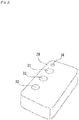
Fig. 1 shows a perspective view showing a state where an illumination device according to the present invention is attached to a frame, and a painting in a state where the illuminance of an incandescent lamp is at the maximum. -
Fig. 2 is a perspective view showing a remote control transmitter unit used for the illumination device. -
Fig. 3 is a bottom view showing a configuration of the illumination device. -
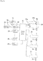
Fig. 4 is a block diagram showing a configuration of a control circuit of the illumination device. -
Fig. 5 is a block diagram showing an internal configuration of the control circuit. -
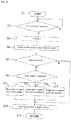
Fig. 6 is a flow chart showing an example of operation of the control circuit of the illumination device. -
Fig. 7 is a flow chart showing an example of operation of the control circuit in a routine process. -
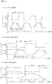
Figs. 8 (a) to 8 (c) are graphs showing examples of a change over time in the illuminance of an ultraviolet lamp and the incandescent lamp. -
Figs. 9(a) and 9(b) are graphs showing example modifications of control patterns shown inFigs. 8(a) to 8(c) . -
Fig. 10 is a perspective view showing a state where the illumination device according to the present invention is attached to a frame, and a painting in a state where the incandescent lamp is turned off. - Hereinafter, specific embodiments of an illumination device according to the present invention, and a frame provided with the illumination device will be described in detail with reference to the drawings.
- As shown in
Fig. 1 , anillumination device 1 is used by being attached to a frame F holding a painting P which is partially drawn with special paint that emits light by ultraviolet rays or that reflects ultraviolet rays. The painting P shown in the present embodiment depicts a scenery of a beach, and the sun, the mountain, the sea, the palm trees and the like are drawn with ordinary paint that is conventionally used, and a crescent moon-shaped figure P2 is drawn with special paint inside a circular figure P1 indicating the sun. Also, in the painting P, P3 indicating light of a light house and a figure P4 which is a reflection of the moonlight from the crescent moon on the surface of the sea are drawn with the special paint. Additionally, each of the figures P2, P3, and P4 drawn with special paint is shown inFig. 1 by broken lines. - Furthermore, as shown in
Fig. 1 , theillumination device 1 includes a devicemain body 2 that is mounted and fixed on the top surface of the frame F, afirst arm 3 whose base end is fixed to the left side of the devicemain body 2, asecond arm 4 whose base end is fixed to the right side of the devicemain body 2, and anillumination unit 5 that is rotatably supported by the tip ends of the first and thesecond arms - A control circuit 23 (see
Fig. 4 ) serving as an illumination control unit for turning on or off first and second illumination lamps described later is built into the devicemain body 2. Also, as shown inFig. 1 , the first and thesecond arms second arms Fig. 4 ) and an ultraviolet lamp (blacklight) 15 (seeFig. 3 ) serving as a first illumination lamp and a firstincandescent lamp 16 to a fourth incandescent lamp 19 (seeFig. 3 ) serving as second illumination lamps, the lamps being disposed inside theillumination unit 5. - Furthermore, as shown in
Fig. 1 , theillumination unit 5 attached to tip end portions of the first and thesecond arms lampshade 6 having two arc-shaped parts Fig. 3 , inside thelampshade 6, there are provided a long and narrow front-side attachment member 8 which is fixed on the inner forward surface of thelampshade 6 by ascrew 7, and a long and narrow rear-side attachment member 9 which is fixed on the inner rearward surface of thelampshade 6 by ascrew 7 and which is parallel to the front-side attachment member 8. Also, as shown inFig. 3 , left andright blocking plates side attachment member 8 and the rear-side attachment member 9 byscrews 10. A pair ofconnectors right blocking plates ultraviolet lamp 15 serving as the first illumination lamp is attached to theconnectors incandescent lamp 16 to the fourthincandescent lamp 19 are linearly attached on the rear side surface of the front-side attachment member 8. - Furthermore, the
ultraviolet lamp 15 and theincandescent lamps 16 to 19 of theillumination device 1 are controlled by the control circuit built into the devicemain body 2. As shown inFig. 4 , the control circuit includes a CPU (Central Processing Unit) 23, and operating power is supplied thereto by apower supply circuit 22 to which power is supplied by acommercial power supply 20 via amain switch 21. Furthermore, theCPU 23 includes a storage unit, which is a storage device (memory), as described later, and is connected to theincandescent lamps 16 to 19 by afirst driver circuit 24 to afourth driver circuit 27, respectively. Also, theultraviolet lamp 15 is connected to thecommercial power supply 20 via themain switch 21 and a switchingelement 30. The switchingelement 30 is controlled by theCPU 23. - Moreover, as shown in
Fig. 4 , a remotecontrol receiver unit 28 serving as a reception device is connected to theCPU 23. The remotecontrol receiver unit 28 receives operation signals issued by a remotecontrol transmitter unit 29 serving as a transmission device, and supplies the signals to theCPU 23. TheCPU 23 is configured to enable various settings described later according to the operation signals. Furthermore, as shown inFig. 4 , asignal reception unit 50 is connected to theCPU 23. Thesignal reception unit 50 receives an analog audio signal, which is a musical piece with noises added thereto, from outside via a microphone (not shown), converts the signal into a digital audio signal, and supplies the digital audio signal to theCPU 23. - Each of the
incandescent lamps 16 to 19 is controlled by theCPU 23 and the corresponding one of thedriver circuits 24 to 27 to repeat turning on and off (see the graphs inFigs. 8 (a) to 8(c) ). As shown inFig. 4 , each of thedriver circuits 24 to 27 is configured from anNPN control transistor 24a whose base terminal is connected to theCPU 23, and aPNP driver transistor 24b whose base terminal is connected to a collector terminal of thecontrol transistor 24a. An emitter terminal of thecontrol transistor 24a is grounded. Also, a power supply voltage Ve is supplied to an emitter terminal of thedriver transistor 24b. Moreover, as shown inFig. 4 , each of theincandescent lamps 16 to 19 has its positive terminal connected to a collector terminal of thedriver transistor 24b and its negative terminal grounded. - Furthermore, the
CPU 23 is provided with a storage unit (not shown) serving as a storage device (memory). For example, the illuminance values of theultraviolet lamp 15 and theincandescent lamps 16 to 19 responsive to temporal changes, that is, the control patterns, are stored in advance in the storage unit as first to third control patterns. Moreover, as shown inFig. 2 , afirst switch 31 to athird switch 33 are provided to the remotecontrol transmitter unit 29. Thefirst switch 31 is for issuing operation signals for starting or stopping operation of theCPU 23. Thesecond switch 32 is for issuing operation signals for stopping each of theincandescent lamps 16 to 19 whose illuminance is being gradually increased or reduced and theultraviolet lamp 15 which is turned on or off so that the illuminance at the time is maintained, and for releasing the stopped state. Thethird switch 33 is for issuing an operation signal for selecting a specific control pattern from a plurality of control patterns, stored in the storage unit, regarding the timings of turning on or off theincandescent lamps 16 to 19 and theultraviolet lamp 15. Moreover, as shown inFig. 2 , the remotecontrol transmitter unit 29 is provided with anerror lamp 34 for displaying to an effect that a predetermined operation of theillumination device 1 is not performed due to short-circuiting of the circuit or the like. - Furthermore, the
illumination device 1 is provided with a first lamp 35 (seeFig. 1 ) serving as an indicator lamp for displaying, by being in a light-on state or light-off state, that theCPU 23 is operating, and that theincandescent lamps 16 to 19 and theultraviolet lamp 15 are maintained at the illuminance at the time point. That is, thefirst lamp 35 is configured to be on in a case where theincandescent lamps 16 to 19 and theultraviolet lamp 15 are maintained at the illuminance at the time point by operation of thesecond switch 32 provided to the remote control transmitter unit 29 (stopped state), and to be off when the stopped state is released. In addition to thefirst lamp 35, theillumination device 1 is also provided with asecond lamp 36, as shown inFig. 1 . Thesecond lamp 36 is for indicating, by the emission color, which control pattern the control pattern which is currently selected by thethird switch 33 provided to the remotecontrol transmitter unit 29 is, and is an indicator lamp constituting the present invention. Moreover, thesecond lamp 36 is configured to be turned on in red when the first control pattern is selected, to be turned on in green when the second control pattern is selected, and to be turned on in orange when the third control pattern is selected, for example. Additionally, thefirst lamp 35 and thesecond lamp 36 provided to theillumination device 1 in the above manner may alternatively be provided to a frame portion of the frame F. -
Fig. 5 is a block diagram showing an internal configuration of theCPU 23. As shown inFig. 5 , theCPU 23 includes a musicalpiece extraction unit 60, and a performancestate detection unit 70. The musicalpiece extraction unit 60 is for extracting, as a musical piece, continuous consonant sounds (hereinafter also referred to as continuous sounds) in a digital audio signal which has been digitally converted by thesignal reception unit 50, and includes a fast Fourier transformer (hereinafter also referred to as FFT) 61 as a data conversion unit, aband extraction unit 62, and a musical piecepresence determination unit 63. The FFT (Fast Fourier Transformer) 61 receives the digital audio signal from thesignal reception unit 50, applies the Fourier transform on the digital audio signal, and generates frequency data. Theband extraction unit 62 extracts data of a specific band corresponding to the continuous sounds from the frequency data. Here, as the specific band, the audible range of human beings may be cited. As the audible range of human beings, a frequency band of 27.5 Hz to 4186 Hz, which is the range of the notes of a piano, may be cited, but the frequency band is not limited to 27.5 Hz to 4186 Hz as long as it is audible to human beings. The musical piecepresence determination unit 63 determines that the musical piece is present in the digital audio signal in response to extraction of data of the specific band by theband extraction unit 62. When the musical piecepresence determination unit 63 determines that the musical piece is present in the digital audio signal, the performancestate detection unit 70 detects start of performance of the musical piece. On the other hand, in a case where the state where data of the specific band is not extracted by theband extraction unit 62 continues for a period of time that is set in advance, the performancestate detection unit 70 detects end of performance of the musical piece. The period of time that is set in advance here may be three seconds, for example. Furthermore, theCPU 23 turns on theultraviolet lamp 15 and theincandescent lamps 16 to 19 at the same time as start of performance of the musical piece is detected, and turns off theultraviolet lamp 15 and theincandescent lamps 16 to 19 at the same time as end of performance of the musical piece is detected. Additionally, the timing of turning off the lamps is not limited to the time of end of performance, and the lamps may be turned off when a predetermined period of time has passed from the end of performance. It is also possible to turn off the lamps before the end of performance by a predetermined period of time. -
Fig. 6 is a flow chart showing operation of the control circuit of the illumination device. As shown inFig. 6 , according to theillumination device 1, when themain switch 21 is switched on, theCPU 23 starts operation in step S1, and in step S2, determines whether thefirst switch 31 is operated or not. Then, if there is no operation of thefirst switch 31, the process stays in step S2, and if there is operation of thefirst switch 31, the process proceeds to step S3. In step S3, the process proceeds to a routine process 1 (seeFig. 7 ). Then, when theroutine process 1 is complete, the process proceeds to step S4. In step S4, theCPU 23 performs a light-on operation according to an initial condition stored in the storage unit. Then, in step S5, whether execution of a control pattern is selected by thesecond switch 32 or not is determined. If execution of a control pattern is not selected, the process proceeds to step S10, and if execution of a control pattern is selected, the process proceeds to step S6. In step S6, theCPU 23 determines which control pattern is selected, and proceeds to step S7 if the first control pattern is selected, proceeds to step S8 if the second control pattern is selected, and proceeds to step S9 if the third control pattern is selected. In step S7, data of the first control pattern is read from the storage unit and is executed, and the process proceeds to step S10. In step S8, data of the second control pattern is read from the storage unit and is executed, and the process proceeds to step S10. In step S9, data of the third control pattern is read from the storage unit and is executed, and the process proceeds to step S10. Then, in step S10, the current lighting state is stored in the storage unit as the initial condition, and the process returns after proceeding to step S11. -
Fig. 7 is a flow chart showing operation of the control circuit in theroutine process 1. As shown inFig. 7 , in theroutine process 1, theCPU 23 starts operation in step T1, and in step T2, determines whether the digital audio signal is received by theFFT 61. Then, if the digital audio signal is not received, the process stays in step T2, and if the digital audio signal is received, the process proceeds to step T3. In step T3, theFFT 61 applies the Fourier transform on the digital audio signal, and generates frequency data. Then, in step T4, theCPU 23 determines whether data of the specific band is extracted from the frequency data by theband extraction unit 62 or not. If data of the specific band is extracted, it is determined that the musical piece is present in the digital audio signal, and the process proceeds to step T8, and if data of the specific band is not extracted, the process proceeds to step T5. In step T5, the performancestate detection unit 70 determines whether a state where data of the specific band is not extracted has continued for a period of time that is set in advance (three seconds) or not. If this state has not continued for the period of time that is set in advance, step T5 is repeated, and if it has continued for the period of time that is set in advance, the process proceeds to step T6. In step T6, the performancestate detection unit 70 detects end of performance of the musical piece, and the process proceeds to step T7. In step T7, theCPU 23 turns off theincandescent lamps 16 to 19 and theultraviolet lamp 15. Then, in step T8, the performancestate detection unit 70 detects start of performance of the musical piece, and theroutine process 1 is ended, and the process proceeds to step T9 to proceed to step S4 inFig. 6 . -
Figs. 8 (a) to 8 (c) are graphs showing examples of a change over time in the illuminance of the ultraviolet lamp and the incandescent lamps.Fig. 8 (a) shows a change over time at the time of execution of the first control pattern.Fig. 8 (b) shows a change over time at the time of execution of the second control pattern.Fig. 8(c) shows a change over time at the time of execution of the third control pattern. According to theillumination device 1, at the time of execution of the first control pattern, as shown inFig. 8(a) , when themain switch 21 is switched on to operate thepower supply circuit 22 and also thefirst switch 31 of the remotecontrol transmitter unit 29 is operated, each of theincandescent lamps 16 to 19 is placed in an on state (is turned on) after a lapse of a predetermined period of time (in this example, 20 seconds), and the illuminance is gradually increased in a first predetermined period of time a (in this example, 20 seconds) to reach its peak. Then, when a second predetermined period of time b (in this example, 25 seconds) has passed after the peak has been reached, each of theincandescent lamps 16 to 19 has its illuminance gradually reduced in a third predetermined period of time c (in this example, 20 seconds) to reach an off state (to be turned off), and is placed in an on state after a lapse of a fourth predetermined period of time d (in this example, 20 seconds), and control is performed to repeat these states. - Also, as shown in
Fig. 8(a) , in the first control pattern, theultraviolet lamp 15 is controlled to repeat a control pattern in which it is turned off during a fifth predetermined period of time e, which is set in advance and which is during the time when theincandescent lamps 16 to 19 are turned on (i.e. the fifth predetermined period of time e is the time from the lapse of half of the first predetermined period of time a to the lapse of half of the third predetermined period of time c: in this example, 45 seconds), and is turned on during a sixth predetermined period of time f, which is set in advance and which includes the time when theincandescent lamps 16 to 19 are turned off (i.e. the sixth predetermined period of time f is the time from the lapse of half of the third predetermined period of time c to the lapse of half of the first predetermined period of time a of the next control pattern: in this example, 40 seconds). - Furthermore, according to the
illumination device 1, at the time of execution of the second control pattern, as shown inFig. 8(b) , when themain switch 21 is switched on to operate thepower supply circuit 22 and also thefirst switch 31 of the remotecontrol transmitter unit 29 is operated, each of theincandescent lamps 16 to 19 is placed in an on state (is turned on) after a lapse of a predetermined period of time (in this example, 50 seconds), and the illuminance is gradually increased in the first predetermined period of time a (in this example, 30 seconds) to reach its peak. Then, when the second predetermined period of time b (in this example, 35 seconds) has passed after the peak has been reached, each of theincandescent lamps 16 to 19 has its illuminance gradually reduced in the third predetermined period of time c (in this example, 30 seconds) to reach an off state (to be turned off), and is placed in an on state after a lapse of the fourth predetermined period of time d (in this example, 50 seconds), and control is performed to repeat these states. - Also, as shown in
Fig. 8(b) , in the second control pattern, theultraviolet lamp 15 is controlled to repeat a control pattern in which it is turned off during the fifth predetermined period of time e, which is set in advance and which is during the time when theincandescent lamps 16 to 19 are turned on (i.e. the fifth predetermined period of time e is the time from the lapse of half of the first predetermined period of time a to the lapse of half of the third predetermined period of time c: in this example, 65 seconds), and is turned on during the sixth predetermined period of time f, which is set in advance and which includes the time when theincandescent lamps 16 to 19 are turned off (i.e. the sixth predetermined period of time f is the time from the lapse of half of the third predetermined period of time c to the lapse of half of the first predetermined period of time a of the next control pattern: in this example, 80 seconds). - Moreover, according to the
illumination device 1, at the time of execution of the third control pattern, as shown inFig. 8(c) , when themain switch 21 is switched on to operate thepower supply circuit 22 and also thefirst switch 31 of the remotecontrol transmitter unit 29 is operated, each of theincandescent lamps 16 to 19 is placed in an on state (is turned on) after a lapse of a predetermined period of time (in this example, 100 seconds), and the illuminance is gradually increased in the first predetermined period of time a (in this example, 60 seconds) to reach its peak. Then, when the second predetermined period of time b (in this example, 40 seconds) has passed after the peak has been reached, each of theincandescent lamps 16 to 19 has its illuminance gradually reduced in the third predetermined period of time c (in this example, 60 seconds) to reach an off state (to be turned off), and is placed in an on state after a lapse of the fourth predetermined period of time d (in this example, 100 seconds), and control is performed to repeat these states. - Also, as shown in
Fig. 8(c) , in the third control pattern, theultraviolet lamp 15 is controlled to repeat a control pattern in which it is turned off during the fifth predetermined period of time e, which is set in advance and which is during the time when theincandescent lamps 16 to 19 are turned on (i.e. the fifth predetermined period of time e is the time from the lapse of half of the first predetermined period of time a to the lapse of half of the third predetermined period of time c: in this example, 100 seconds), and is turned on during the sixth predetermined period of time f, which is set in advance and which includes the time when theincandescent lamps 16 to 19 are turned off (i.e. the sixth predetermined period of time f is the time from the lapse of half of the third predetermined period of time c to the lapse of half of the first predetermined period of time a of the next control pattern: in this example, 160 seconds). - Additionally, the time when the
ultraviolet lamp 15 is turned off (the fifth predetermined period of time e) may be controlled to be longer than the time when the illuminance of each of theincandescent lamps 16 to 19 is maintained at its peak, that is, the second predetermined period of time b as described above, but it may alternatively coincide with the second predetermined period of time b, as shown inFig. 9(a) , or it may be controlled to be shorter than the second predetermined period of time b, as shown inFig. 9(b) . Also, the illuminance of theultraviolet lamp 15 may be controlled to be higher, equal to, or lower than the peak of the illuminance of each of theincandescent lamps 16 to 19. - That is, according to the
illumination device 1, when themain switch 21 is operated to be on and thefirst switch 31 of the remotecontrol transmitter unit 29 is operated, theultraviolet lamp 15 is turned on, and also theCPU 23 is operated by thepower supply circuit 22, and theincandescent lamps 16 to 19 and theultraviolet lamp 15 are repeatedly turned on and off according to any of the first to the third control patterns shown inFigs. 8(a) to 8(c) , respectively, which are stored in the storage unit (not shown) of theCPU 23. At this time, illuminance values are read from the storage unit (not shown) by theCPU 23 according to the lapse of time, and the base current of thecontrol transistor 24a is controlled by a DA converter, not shown, provided to theCPU 23. Then, the current flowing from the emitter of thedriver transistor 24b to the collector is changed, and the value of current (illuminance) flowing to each of theincandescent lamps 16 to 19 is controlled. - Additionally, to stop changing the illuminance of the
incandescent lamps 16 to 19 and theultraviolet lamp 15 during control of the illuminance and to maintain the illuminance at the time point, thesecond switch 32 provided to the remotecontrol transmitter unit 29 is operated. Moreover, to change (select) the control pattern of change of the illuminance of theincandescent lamps 16 to 19 and theultraviolet lamp 15, thethird switch 33 is operated. - As described above, according to the
illumination device 1 of the present invention including each of theincandescent lamps 16 to 19 whose illuminance is changed according to a predetermined control pattern and theultraviolet lamp 15 which is turned on or off according to a change in the illuminance of theincandescent lamps 16 to 19, when only theultraviolet lamp 15 is turned on and theincandescent lamps 16 to 19 are turned off, the entire painting P is seen to be quite dark, as shown inFig. 10 . Also, at this time, the crescent moon-shaped figure P2, the figure P3 indicating light of a light house, and the figure P4, which is a reflection of the moonlight on the surface of the sea, which are painted with special painting that is caused to emit or reflect light by the ultraviolet rays from theultraviolet lamp 15, are shown shining brighter than other parts painted with other paints. Accordingly, at this time, the painting P is viewed as showing a nighttime scenery. - Then, when a predetermined period of time passes from this state, the
incandescent lamps 16 to 19 are turned on and their illuminance is gradually increased, as shown inFigs. 8(a) to 8(c) . When the illuminance of theincandescent lamps 16 to 19 is increased, the brightness of the entire painting P is increased little by little. At this time, the figures P2, P3, and P4 painted with the special paint gradually become unrecognizable, and then, when theultraviolet lamp 15 is turned off and the illuminance of theincandescent lamps 16 to 19 reach its maximum, the figures P2, P3, and P4 become entirely unrecognizable. Accordingly, the entire painting P is viewed as showing a daytime scenery. - As described above, when the
illumination device 1 is used on the painting P which is at least partially drawn with the special paint that emits light or reflects ultraviolet rays when irradiated with ultraviolet rays, the scenery shown in the painting P may be caused to gradually change according to a change in the nature over time, from a nighttime scenery to a morning scenery, a daytime scenery, an evening scenery, and a nighttime scenery. Accordingly, theillumination device 1 and a frame provided with the illumination device may offer a viewer a sense of ambience and a sense of surprise due to the change, and may thus offer deep relaxation. - Furthermore, according to the
illumination device 1, theCPU 23 turns on theincandescent lamps 16 to 19 and theultraviolet lamp 15 in response to detection of start of performance by the performancestate detection unit 70, and turns off theincandescent lamps 16 to 19 and theultraviolet lamp 15 in response to detection of end of performance by the performancestate detection unit 70, and thus it is possible to fully meet the demand of viewers who want to enjoy viewing the painting P while listening to a musical piece, with sound providing a great sense of ambience. Accordingly, viewers may experience greater relaxation by listening to a musical piece while viewing the painting P. - While the embodiment of the present invention has been described with reference to the attached drawings, specific configurations are not limited to the embodiment. The scope of the present invention is defined not by the description of the embodiment, but by the appended claims, and includes all the equivalents and modifications falling within the scope of the appended claims.
- Additionally, in the embodiment described above, a first illumination lamp, which is the ultraviolet lamp, and a second illumination lamp, which is the incandescent lamp, constituting the illumination device of the present invention are described to be provided to the
illumination unit 5 which is rotatably supported at the tip ends of the first and thesecond arms illumination unit 5, and for example, the ultraviolet lamp, which is the first illumination lamp, may be attached to each of the left and right sides of a frame, not shown, where a painting is fixed, and the incandescent lamp, which is the second illumination lamp, may be attached to each of the upper and lower sides of the frame. - Furthermore, in the embodiment described above, the second illumination lamp is described to include four
incandescent lamps 16 to 19. However, the number of incandescent lamps is not limited to four, and may be changed to three or less, or five or more. - Moreover, in the embodiment described above, an example is described where the first illumination lamp is configured by an ultraviolet lamp, and the second illumination lamp is configured by an incandescent lamp, but the present invention is not limited thereto, and the first illumination lamp may be configured by an ultraviolet LED (Light Emitting Diode), and the second illumination lamp may be configured by a white LED.
- Moreover, in the embodiment described above, an example is described where an operation signal is issued by the remote
control transmitter unit 29 serving as a transmission device to the remotecontrol receiver unit 28 serving as a reception device to control on and off of theincandescent lamps 16 to 19 and theultraviolet lamp 15, but the present invention is not limited thereto. For example, a mobile terminal capable of executing an application including a function of narrating information about a painting (guide function) or a function of reciting a poem written for each painting may be used to constitute the remote control transmitter unit serving as a transmission device, and the narration function or the recitation function may be executed according to an operation of selecting a painting by a viewer of paintings. The "mobile terminal" here may be configured by using a mobile information terminal or the like such as a smartphone, a cell phone, a tablet PC (Personal Computer) or a PDA (Personal Digital Assistant). The "narration of information about a painting" or "recitation of a poem" may be realized by output of audio from headphones connected to an earphone jack (a hole for plugging in the cord of an earphone) of a mobile terminal, or by performing transmission/reception of audio information by using near field communication compliant with near field communication standards such as Bluetooth or transmission/reception of infrared rays and by outputting audio from a speaker of the transmission device. Additionally, a viewer of paintings may freely switch between on and off of the narration function or the recitation function. Also, the viewer of paintings may freely change the pitch or speed of audio of the narration function or the recitation function. Furthermore, the narration function or the recitation function may be enhanced by realizing narration or recitation in multiple languages in consideration of foreigners viewing the paintings. -
- 1: Illumination device
- 2: Device main body
- 3, 4: Arm
- 5: Illumination unit
- 6: Lampshade
- 6a, 6b: Arc-shaped part
- 7, 10: Screw
- 8: Front-side attachment member
- 9: Rear-side attachment member
- 11: Blocking plate
- 13: Connector
- 15: Ultraviolet lamp (first illumination lamp)
- 16, 17, 18 19: Incandescent lamp (second illumination lamp)
- 20: Commercial power supply
- 21: Main switch
- 22: Power supply circuit
- 23: CPU (illumination control unit)
- 24, 25, 26, 27: Driver circuit
- 24a: Control transistor
- 24b: Driver transistor
- 28: Remote control receiver unit
- 29: Remote control transmitter unit
- 30: Switching element
- 31, 32, 33: Switch
- 34: Error lamp
- 35, 36: Lamp
- 50: Signal reception unit
- 60: Musical piece extraction unit
- 61: FFT (data conversion unit)
- 62: Band extraction unit
- 63: Musical piece presence determination unit
- 70: Performance state detection unit
Claims (9)
- An illumination device comprising:a signal reception unit capable of receiving an audio signal from outside;a musical piece extraction unit capable of extracting continuous consonant sounds in the audio signal as a musical piece;a performance state detection unit capable of detecting start/end of performance of the musical piece according to a result of extraction by the musical piece extraction unit;a first illumination lamp capable of radiating ultraviolet rays;a second illumination lamp capable of radiating white light; andan illumination control unit capable of controlling on/off of the first illumination lamp, and of controlling on/off and illuminance of the second illumination lamp,wherein the illumination control unitcontrols the second illumination lamp to repeat a pattern in which illuminance is gradually increased in a first predetermined period of time that is set in advance starting from an off state, maximum illuminance is maintained in a second predetermined period of time that is set in advance and that follows the first predetermined period of time, the illuminance is gradually reduced in a third predetermined period of time that is set in advance and that follows the second predetermined period of time, and the off state is maintained in a fourth predetermined period of time that is set in advance and that follows the third predetermined period of time,controls the first illumination lamp to repeat a pattern of being turned off in a fifth predetermined period of time that is set in advance and that is during a time when the second illumination lamp is turned on, and being turned on in a sixth predetermined period of time that is set in advance and that includes a time when the second illumination lamp is turned off,causes the first and the second illumination lamps to be turned on in response to detection of the start of performance by the performance state detection unit, andcauses the first and the second illumination lamps to be turned off in response to detection of the end of performance by the performance state detection unit.
- The illumination device according to claim 1, wherein the musical piece extraction unit includes
a data conversion unit capable of generating frequency data by applying Fourier transform on data of the audio signal,
a band extraction unit capable of extracting data of a specific band corresponding to the continuous consonant sounds from the frequency data, and
a musical piece presence determination unit for determining that the musical piece is present in the audio signal, in response to extraction of the data of the specific band by the band extraction unit. - The illumination device according to claim 2, wherein the performance state detection unit
detects the start of performance when the musical piece presence determination unit determines that the musical piece is present in the audio signal, and
detects the end of performance when a state where the data of the specific band is not extracted by the band extraction unit continues for a period of time that is set in advance. - The illumination device according to any one of claims 1 to 3, wherein the illumination control unit includes a storage device storing a plurality of control patterns, and selects one control pattern by selecting from the plurality of control patterns and performs control according to the one control pattern selected.
- The illumination device according to any one of claims 1 to 4, comprising:a transmission device for issuing an operation signal; anda reception device for receiving, and supplying to the illumination control unit, the operation signal from the transmission device,wherein the illumination control unit performs selection of a control pattern according to the operation signal.
- The illumination device according to any one of claims 1 to 5, comprising an indicator lamp for emitting light of a plurality of colors,
wherein the indicator lamp emits light of a color corresponding to a control pattern according to any one control pattern selected. - The illumination device according to any one of claims 1 to 6, wherein the first illumination lamp is one of an ultraviolet lamp and an ultraviolet LED.
- The illumination device according to any one of claims 1 to 7, wherein the second illumination lamp is one of an incandescent lamp and a white LED.
- A frame, wherein the frame is provided with the illumination device according to any one of claims 1 to 8.
Priority Applications (4)
| Application Number | Priority Date | Filing Date | Title |
|---|---|---|---|
| RS20191625A RS59680B1 (en) | 2013-12-24 | 2014-12-24 | Lighting device and frame with said lighting device attached thereto |
| SI201431422T SI3102004T1 (en) | 2013-12-24 | 2014-12-24 | Lighting device and frame with said lighting device attached thereto |
| PL14873521T PL3102004T3 (en) | 2013-12-24 | 2014-12-24 | Lighting device and frame with said lighting device attached thereto |
| HRP20192272TT HRP20192272T1 (en) | 2013-12-24 | 2019-12-17 | Lighting device and frame with said lighting device attached thereto |
Applications Claiming Priority (2)
| Application Number | Priority Date | Filing Date | Title |
|---|---|---|---|
| JP2013265341A JP5667279B1 (en) | 2013-12-24 | 2013-12-24 | Illumination device and frame to which this illumination device is attached |
| PCT/JP2014/084173 WO2015098974A1 (en) | 2013-12-24 | 2014-12-24 | Lighting device and frame with said lighting device attached thereto |
Publications (3)
| Publication Number | Publication Date |
|---|---|
| EP3102004A1 true EP3102004A1 (en) | 2016-12-07 |
| EP3102004A4 EP3102004A4 (en) | 2017-11-22 |
| EP3102004B1 EP3102004B1 (en) | 2019-10-09 |
Family
ID=52569493
Family Applications (1)
| Application Number | Title | Priority Date | Filing Date |
|---|---|---|---|
| EP14873521.0A Active EP3102004B1 (en) | 2013-12-24 | 2014-12-24 | Lighting device and frame with said lighting device attached thereto |
Country Status (21)
| Country | Link |
|---|---|
| US (1) | US9807854B2 (en) |
| EP (1) | EP3102004B1 (en) |
| JP (1) | JP5667279B1 (en) |
| KR (2) | KR20160144956A (en) |
| CN (1) | CN105874885B (en) |
| AU (2) | AU2014371047A1 (en) |
| CY (1) | CY1122621T1 (en) |
| DK (1) | DK3102004T3 (en) |
| ES (1) | ES2758509T3 (en) |
| HK (1) | HK1222972A1 (en) |
| HR (1) | HRP20192272T1 (en) |
| HU (1) | HUE046472T2 (en) |
| IL (1) | IL246331B (en) |
| MY (1) | MY177696A (en) |
| PH (1) | PH12016501248B1 (en) |
| PL (1) | PL3102004T3 (en) |
| PT (1) | PT3102004T (en) |
| RS (1) | RS59680B1 (en) |
| SG (1) | SG11201605201YA (en) |
| SI (1) | SI3102004T1 (en) |
| WO (1) | WO2015098974A1 (en) |
Families Citing this family (1)
| Publication number | Priority date | Publication date | Assignee | Title |
|---|---|---|---|---|
| US10180248B2 (en) | 2015-09-02 | 2019-01-15 | ProPhotonix Limited | LED lamp with sensing capabilities |
Family Cites Families (11)
| Publication number | Priority date | Publication date | Assignee | Title |
|---|---|---|---|---|
| JP2829503B2 (en) * | 1995-11-17 | 1998-11-25 | 株式会社タイムリーエレガンス | Lighting device and picture frame to which the lighting device is attached |
| JP2880476B2 (en) * | 1996-11-28 | 1999-04-12 | 株式会社タイムリーエレガンス | Lighting device and picture frame to which the lighting device is attached |
| GB2354602A (en) * | 1999-09-07 | 2001-03-28 | Peter Stefan Jones | Digital controlling system for electronic lighting devices |
| WO2001099475A1 (en) * | 2000-06-21 | 2001-12-27 | Color Kinetics Incorporated | Method and apparatus for controlling a lighting system in response to an audio input |
| JP2006034321A (en) * | 2004-07-22 | 2006-02-09 | Agi:Kk | Trick art frame |
| US7451077B1 (en) * | 2004-09-23 | 2008-11-11 | Felicia Lindau | Acoustic presentation system and method |
| US7997772B2 (en) * | 2007-08-09 | 2011-08-16 | Fasst Products, Llc | Flameless candle with multimedia capabilities |
| CN102106187A (en) * | 2008-06-16 | 2011-06-22 | 塔卡国际株式会社 | Lighting apparatus for display, and display unit |
| JP3150724U (en) * | 2009-03-12 | 2009-05-28 | 悦子 開高 | 3D picture frame |
| JP2010263040A (en) * | 2009-05-01 | 2010-11-18 | Konica Minolta Holdings Inc | Lighting device and lighting system |
| JP5267606B2 (en) * | 2011-03-30 | 2013-08-21 | カシオ計算機株式会社 | Display device and program |
-
2013
- 2013-12-24 JP JP2013265341A patent/JP5667279B1/en active Active
-
2014
- 2014-12-24 ES ES14873521T patent/ES2758509T3/en active Active
- 2014-12-24 MY MYPI2016702325A patent/MY177696A/en unknown
- 2014-12-24 AU AU2014371047A patent/AU2014371047A1/en not_active Abandoned
- 2014-12-24 PT PT148735210T patent/PT3102004T/en unknown
- 2014-12-24 DK DK14873521.0T patent/DK3102004T3/en active
- 2014-12-24 SI SI201431422T patent/SI3102004T1/en unknown
- 2014-12-24 US US15/107,720 patent/US9807854B2/en active Active
- 2014-12-24 KR KR1020167020154A patent/KR20160144956A/en not_active Application Discontinuation
- 2014-12-24 CN CN201480071019.3A patent/CN105874885B/en active Active
- 2014-12-24 PL PL14873521T patent/PL3102004T3/en unknown
- 2014-12-24 RS RS20191625A patent/RS59680B1/en unknown
- 2014-12-24 EP EP14873521.0A patent/EP3102004B1/en active Active
- 2014-12-24 WO PCT/JP2014/084173 patent/WO2015098974A1/en active Application Filing
- 2014-12-24 HU HUE14873521A patent/HUE046472T2/en unknown
- 2014-12-24 SG SG11201605201YA patent/SG11201605201YA/en unknown
- 2014-12-24 KR KR1020217030330A patent/KR102345027B1/en active IP Right Grant
-
2016
- 2016-06-20 IL IL246331A patent/IL246331B/en active IP Right Grant
- 2016-06-24 PH PH12016501248A patent/PH12016501248B1/en unknown
- 2016-09-21 HK HK16111044.5A patent/HK1222972A1/en unknown
-
2017
- 2017-11-15 AU AU2017261532A patent/AU2017261532B9/en active Active
-
2019
- 2019-12-17 HR HRP20192272TT patent/HRP20192272T1/en unknown
- 2019-12-30 CY CY20191101362T patent/CY1122621T1/en unknown
Also Published As
| Publication number | Publication date |
|---|---|
| PL3102004T3 (en) | 2020-04-30 |
| MY177696A (en) | 2020-09-23 |
| EP3102004B1 (en) | 2019-10-09 |
| HRP20192272T1 (en) | 2020-03-06 |
| ES2758509T3 (en) | 2020-05-05 |
| EP3102004A4 (en) | 2017-11-22 |
| HK1222972A1 (en) | 2017-07-14 |
| AU2017261532B9 (en) | 2020-03-19 |
| KR102345027B1 (en) | 2021-12-29 |
| KR20210120122A (en) | 2021-10-06 |
| SG11201605201YA (en) | 2016-08-30 |
| RS59680B1 (en) | 2020-01-31 |
| PT3102004T (en) | 2019-12-19 |
| CY1122621T1 (en) | 2021-05-05 |
| PH12016501248A1 (en) | 2016-08-15 |
| JP2015122199A (en) | 2015-07-02 |
| CN105874885B (en) | 2019-01-22 |
| DK3102004T3 (en) | 2020-01-20 |
| US20160323973A1 (en) | 2016-11-03 |
| US9807854B2 (en) | 2017-10-31 |
| HUE046472T2 (en) | 2020-03-30 |
| CN105874885A (en) | 2016-08-17 |
| KR20160144956A (en) | 2016-12-19 |
| IL246331B (en) | 2020-06-30 |
| IL246331A0 (en) | 2016-08-31 |
| AU2017261532B2 (en) | 2019-11-21 |
| WO2015098974A1 (en) | 2015-07-02 |
| AU2014371047A1 (en) | 2016-07-28 |
| JP5667279B1 (en) | 2015-02-12 |
| AU2017261532A1 (en) | 2017-12-07 |
| PH12016501248B1 (en) | 2016-08-15 |
| SI3102004T1 (en) | 2020-01-31 |
Similar Documents
| Publication | Publication Date | Title |
|---|---|---|
| KR101670741B1 (en) | Illuminator | |
| US20140091719A1 (en) | Christmas string light control system and string light device thereof | |
| US20170211803A1 (en) | Acousto-optic audio signal cable | |
| KR200465111Y1 (en) | Desk lamp interlocking with smart phone | |
| US9769908B2 (en) | Audio reproduction device | |
| JP2017539056A (en) | Lighting control apparatus and method | |
| KR101729522B1 (en) | Using voice recognition control system for controling lighting | |
| AU2017261532B9 (en) | Illumination device, and frame provided with the same | |
| US20070132748A1 (en) | Screen display with sound lamps | |
| TW201616493A (en) | System for alternating lighting of DRAM | |
| US20060178888A1 (en) | Voice bulb | |
| KR200418945Y1 (en) | Led lighting apparatus | |
| CN201731425U (en) | LED intelligent voice tree lamp | |
| CN201601808U (en) | Luminous earphones | |
| KR101398820B1 (en) | Decoration three-dimensional artwork for controlling with wireless and control system of three-dimensional artwork using mobile communication terminal | |
| JP4056499B2 (en) | Method and apparatus for controlling light emission flicker of cold cathode with digital sound source of motherboard | |
| US20060044784A1 (en) | Ornamental light string | |
| CN215453221U (en) | Luminous earphone control system | |
| KR101133231B1 (en) | A device of flashlight through the headset jack of portable terminal device | |
| CN203327293U (en) | Intelligent light string remote control device | |
| CN210958665U (en) | Bluetooth sound lamp string | |
| TW201810040A (en) | System for alternating lighting of DRAM | |
| CN203261463U (en) | LED Bluetooth sound equipment | |
| CN205640499U (en) | Luminous device in loudspeaker place ahead enables | |
| CN105376908A (en) | WIFI down lamp |
Legal Events
| Date | Code | Title | Description |
|---|---|---|---|
| PUAI | Public reference made under article 153(3) epc to a published international application that has entered the european phase |
Free format text: ORIGINAL CODE: 0009012 |
|
| 17P | Request for examination filed |
Effective date: 20160719 |
|
| AK | Designated contracting states |
Kind code of ref document: A1 Designated state(s): AL AT BE BG CH CY CZ DE DK EE ES FI FR GB GR HR HU IE IS IT LI LT LU LV MC MK MT NL NO PL PT RO RS SE SI SK SM TR |
|
| AX | Request for extension of the european patent |
Extension state: BA ME |
|
| DAX | Request for extension of the european patent (deleted) | ||
| A4 | Supplementary search report drawn up and despatched |
Effective date: 20171019 |
|
| RIC1 | Information provided on ipc code assigned before grant |
Ipc: F21V 33/00 20060101ALI20171013BHEP Ipc: G10L 25/18 20130101ALI20171013BHEP Ipc: G10L 25/78 20130101ALI20171013BHEP Ipc: H05B 37/02 20060101AFI20171013BHEP |
|
| 17Q | First examination report despatched |
Effective date: 20180705 |
|
| GRAP | Despatch of communication of intention to grant a patent |
Free format text: ORIGINAL CODE: EPIDOSNIGR1 |
|
| INTG | Intention to grant announced |
Effective date: 20190517 |
|
| RIN1 | Information on inventor provided before grant (corrected) |
Inventor name: NAKANO, KAZUO |
|
| GRAS | Grant fee paid |
Free format text: ORIGINAL CODE: EPIDOSNIGR3 |
|
| GRAA | (expected) grant |
Free format text: ORIGINAL CODE: 0009210 |
|
| AK | Designated contracting states |
Kind code of ref document: B1 Designated state(s): AL AT BE BG CH CY CZ DE DK EE ES FI FR GB GR HR HU IE IS IT LI LT LU LV MC MK MT NL NO PL PT RO RS SE SI SK SM TR |
|
| REG | Reference to a national code |
Ref country code: GB Ref legal event code: FG4D |
|
| REG | Reference to a national code |
Ref country code: CH Ref legal event code: EP |
|
| REG | Reference to a national code |
Ref country code: IE Ref legal event code: FG4D |
|
| REG | Reference to a national code |
Ref country code: DE Ref legal event code: R096 Ref document number: 602014055066 Country of ref document: DE |
|
| REG | Reference to a national code |
Ref country code: AT Ref legal event code: REF Ref document number: 1190360 Country of ref document: AT Kind code of ref document: T Effective date: 20191115 |
|
| REG | Reference to a national code |
Ref country code: HR Ref legal event code: TUEP Ref document number: P20192272T Country of ref document: HR |
|
| REG | Reference to a national code |
Ref country code: RO Ref legal event code: EPE |
|
| REG | Reference to a national code |
Ref country code: PT Ref legal event code: SC4A Ref document number: 3102004 Country of ref document: PT Date of ref document: 20191219 Kind code of ref document: T Free format text: AVAILABILITY OF NATIONAL TRANSLATION Effective date: 20191212 |
|
| REG | Reference to a national code |
Ref country code: CH Ref legal event code: NV Representative=s name: DENNEMEYER AG, CH |
|
| REG | Reference to a national code |
Ref country code: NO Ref legal event code: T2 Effective date: 20191009 |
|
| REG | Reference to a national code |
Ref country code: DK Ref legal event code: T3 Effective date: 20200117 |
|
| REG | Reference to a national code |
Ref country code: NL Ref legal event code: FP |
|
| REG | Reference to a national code |
Ref country code: SE Ref legal event code: TRGR |
|
| REG | Reference to a national code |
Ref country code: HR Ref legal event code: ODRP Ref document number: P20192272T Country of ref document: HR Payment date: 20191223 Year of fee payment: 6 |
|
| REG | Reference to a national code |
Ref country code: SK Ref legal event code: T3 Ref document number: E 32977 Country of ref document: SK |
|
| REG | Reference to a national code |
Ref country code: HR Ref legal event code: T1PR Ref document number: P20192272 Country of ref document: HR |
|
| REG | Reference to a national code |
Ref country code: EE Ref legal event code: FG4A Ref document number: E018666 Country of ref document: EE Effective date: 20191212 |
|
| REG | Reference to a national code |
Ref country code: HU Ref legal event code: AG4A Ref document number: E046472 Country of ref document: HU |
|
| REG | Reference to a national code |
Ref country code: GR Ref legal event code: EP Ref document number: 20190403754 Country of ref document: GR Effective date: 20200318 |
|
| REG | Reference to a national code |
Ref country code: ES Ref legal event code: FG2A Ref document number: 2758509 Country of ref document: ES Kind code of ref document: T3 Effective date: 20200505 |
|
| REG | Reference to a national code |
Ref country code: DE Ref legal event code: R097 Ref document number: 602014055066 Country of ref document: DE |
|
| PLBE | No opposition filed within time limit |
Free format text: ORIGINAL CODE: 0009261 |
|
| STAA | Information on the status of an ep patent application or granted ep patent |
Free format text: STATUS: NO OPPOSITION FILED WITHIN TIME LIMIT |
|
| 26N | No opposition filed |
Effective date: 20200710 |
|
| REG | Reference to a national code |
Ref country code: HR Ref legal event code: ODRP Ref document number: P20192272 Country of ref document: HR Payment date: 20201216 Year of fee payment: 7 |
|
| REG | Reference to a national code |
Ref country code: HR Ref legal event code: ODRP Ref document number: P20192272 Country of ref document: HR Payment date: 20211222 Year of fee payment: 8 |
|
| REG | Reference to a national code |
Ref country code: AT Ref legal event code: UEP Ref document number: 1190360 Country of ref document: AT Kind code of ref document: T Effective date: 20191009 |
|
| REG | Reference to a national code |
Ref country code: HR Ref legal event code: ODRP Ref document number: P20192272 Country of ref document: HR Payment date: 20221216 Year of fee payment: 9 |
|
| PGFP | Annual fee paid to national office [announced via postgrant information from national office to epo] |
Ref country code: DE Payment date: 20221213 Year of fee payment: 9 |
|
| PGFP | Annual fee paid to national office [announced via postgrant information from national office to epo] |
Ref country code: PL Payment date: 20221219 Year of fee payment: 9 Ref country code: BE Payment date: 20221221 Year of fee payment: 9 |
|
| PGFP | Annual fee paid to national office [announced via postgrant information from national office to epo] |
Ref country code: MK Payment date: 20221213 Year of fee payment: 9 |
|
| PGFP | Annual fee paid to national office [announced via postgrant information from national office to epo] |
Ref country code: TR Payment date: 20221223 Year of fee payment: 9 Ref country code: ES Payment date: 20230228 Year of fee payment: 9 Ref country code: CH Payment date: 20230103 Year of fee payment: 9 |
|
| PGFP | Annual fee paid to national office [announced via postgrant information from national office to epo] |
Ref country code: IT Payment date: 20221228 Year of fee payment: 9 Ref country code: CY Payment date: 20221222 Year of fee payment: 9 |
|
| PGFP | Annual fee paid to national office [announced via postgrant information from national office to epo] |
Ref country code: AL Payment date: 20221218 Year of fee payment: 9 |
|
| REG | Reference to a national code |
Ref country code: HR Ref legal event code: ODRP Ref document number: P20192272 Country of ref document: HR Payment date: 20231220 Year of fee payment: 10 |
|
| PGFP | Annual fee paid to national office [announced via postgrant information from national office to epo] |
Ref country code: SK Payment date: 20231220 Year of fee payment: 10 |
|
| PGFP | Annual fee paid to national office [announced via postgrant information from national office to epo] |
Ref country code: GB Payment date: 20231227 Year of fee payment: 10 Ref country code: GR Payment date: 20231227 Year of fee payment: 10 |
|
| PGFP | Annual fee paid to national office [announced via postgrant information from national office to epo] |
Ref country code: MC Payment date: 20231227 Year of fee payment: 10 |
|
| PGFP | Annual fee paid to national office [announced via postgrant information from national office to epo] |
Ref country code: IS Payment date: 20231229 Year of fee payment: 10 |
|
| PGFP | Annual fee paid to national office [announced via postgrant information from national office to epo] |
Ref country code: SM Payment date: 20231228 Year of fee payment: 10 Ref country code: SI Payment date: 20231221 Year of fee payment: 10 Ref country code: SE Payment date: 20231227 Year of fee payment: 10 Ref country code: RS Payment date: 20231222 Year of fee payment: 10 Ref country code: RO Payment date: 20231218 Year of fee payment: 10 Ref country code: PT Payment date: 20231213 Year of fee payment: 10 Ref country code: NO Payment date: 20231228 Year of fee payment: 10 Ref country code: NL Payment date: 20231227 Year of fee payment: 10 Ref country code: MT Payment date: 20231228 Year of fee payment: 10 Ref country code: LV Payment date: 20231221 Year of fee payment: 10 Ref country code: LU Payment date: 20231227 Year of fee payment: 10 Ref country code: LT Payment date: 20231227 Year of fee payment: 10 Ref country code: IE Payment date: 20231227 Year of fee payment: 10 Ref country code: HU Payment date: 20231215 Year of fee payment: 10 Ref country code: HR Payment date: 20231220 Year of fee payment: 10 Ref country code: FR Payment date: 20231222 Year of fee payment: 10 Ref country code: FI Payment date: 20231227 Year of fee payment: 10 Ref country code: EE Payment date: 20231227 Year of fee payment: 10 Ref country code: DK Payment date: 20231227 Year of fee payment: 10 Ref country code: CZ Payment date: 20231214 Year of fee payment: 10 Ref country code: BG Payment date: 20231228 Year of fee payment: 10 Ref country code: AT Payment date: 20231227 Year of fee payment: 10 |
|
| PGFP | Annual fee paid to national office [announced via postgrant information from national office to epo] |
Ref country code: PL Payment date: 20231222 Year of fee payment: 10 Ref country code: BE Payment date: 20231227 Year of fee payment: 10 |
|
| PGFP | Annual fee paid to national office [announced via postgrant information from national office to epo] |
Ref country code: MK Payment date: 20231221 Year of fee payment: 10 |
|
| PGFP | Annual fee paid to national office [announced via postgrant information from national office to epo] |
Ref country code: ES Payment date: 20240228 Year of fee payment: 10 |