EP3101912A1 - Laminated ultrasonic vibration device and ultrasonic medical apparatus - Google Patents
Laminated ultrasonic vibration device and ultrasonic medical apparatus Download PDFInfo
- Publication number
- EP3101912A1 EP3101912A1 EP15739798.5A EP15739798A EP3101912A1 EP 3101912 A1 EP3101912 A1 EP 3101912A1 EP 15739798 A EP15739798 A EP 15739798A EP 3101912 A1 EP3101912 A1 EP 3101912A1
- Authority
- EP
- European Patent Office
- Prior art keywords
- thickness
- piezoelectric
- single crystal
- mass
- ultrasound
- Prior art date
- Legal status (The legal status is an assumption and is not a legal conclusion. Google has not performed a legal analysis and makes no representation as to the accuracy of the status listed.)
- Granted
Links
Images



Classifications
-
- B—PERFORMING OPERATIONS; TRANSPORTING
- B06—GENERATING OR TRANSMITTING MECHANICAL VIBRATIONS IN GENERAL
- B06B—METHODS OR APPARATUS FOR GENERATING OR TRANSMITTING MECHANICAL VIBRATIONS OF INFRASONIC, SONIC, OR ULTRASONIC FREQUENCY, e.g. FOR PERFORMING MECHANICAL WORK IN GENERAL
- B06B1/00—Methods or apparatus for generating mechanical vibrations of infrasonic, sonic, or ultrasonic frequency
- B06B1/02—Methods or apparatus for generating mechanical vibrations of infrasonic, sonic, or ultrasonic frequency making use of electrical energy
- B06B1/06—Methods or apparatus for generating mechanical vibrations of infrasonic, sonic, or ultrasonic frequency making use of electrical energy operating with piezoelectric effect or with electrostriction
- B06B1/0607—Methods or apparatus for generating mechanical vibrations of infrasonic, sonic, or ultrasonic frequency making use of electrical energy operating with piezoelectric effect or with electrostriction using multiple elements
- B06B1/0611—Methods or apparatus for generating mechanical vibrations of infrasonic, sonic, or ultrasonic frequency making use of electrical energy operating with piezoelectric effect or with electrostriction using multiple elements in a pile
-
- A—HUMAN NECESSITIES
- A61—MEDICAL OR VETERINARY SCIENCE; HYGIENE
- A61B—DIAGNOSIS; SURGERY; IDENTIFICATION
- A61B17/00—Surgical instruments, devices or methods
- A61B17/32—Surgical cutting instruments
- A61B17/320068—Surgical cutting instruments using mechanical vibrations, e.g. ultrasonic
-
- B—PERFORMING OPERATIONS; TRANSPORTING
- B06—GENERATING OR TRANSMITTING MECHANICAL VIBRATIONS IN GENERAL
- B06B—METHODS OR APPARATUS FOR GENERATING OR TRANSMITTING MECHANICAL VIBRATIONS OF INFRASONIC, SONIC, OR ULTRASONIC FREQUENCY, e.g. FOR PERFORMING MECHANICAL WORK IN GENERAL
- B06B3/00—Methods or apparatus specially adapted for transmitting mechanical vibrations of infrasonic, sonic, or ultrasonic frequency
-
- H—ELECTRICITY
- H10—SEMICONDUCTOR DEVICES; ELECTRIC SOLID-STATE DEVICES NOT OTHERWISE PROVIDED FOR
- H10N—ELECTRIC SOLID-STATE DEVICES NOT OTHERWISE PROVIDED FOR
- H10N30/00—Piezoelectric or electrostrictive devices
- H10N30/01—Manufacture or treatment
- H10N30/05—Manufacture of multilayered piezoelectric or electrostrictive devices, or parts thereof, e.g. by stacking piezoelectric bodies and electrodes
- H10N30/057—Manufacture of multilayered piezoelectric or electrostrictive devices, or parts thereof, e.g. by stacking piezoelectric bodies and electrodes by stacking bulk piezoelectric or electrostrictive bodies and electrodes
-
- H—ELECTRICITY
- H10—SEMICONDUCTOR DEVICES; ELECTRIC SOLID-STATE DEVICES NOT OTHERWISE PROVIDED FOR
- H10N—ELECTRIC SOLID-STATE DEVICES NOT OTHERWISE PROVIDED FOR
- H10N30/00—Piezoelectric or electrostrictive devices
- H10N30/80—Constructional details
- H10N30/87—Electrodes or interconnections, e.g. leads or terminals
- H10N30/871—Single-layered electrodes of multilayer piezoelectric or electrostrictive devices, e.g. internal electrodes
-
- A—HUMAN NECESSITIES
- A61—MEDICAL OR VETERINARY SCIENCE; HYGIENE
- A61B—DIAGNOSIS; SURGERY; IDENTIFICATION
- A61B17/00—Surgical instruments, devices or methods
- A61B17/32—Surgical cutting instruments
- A61B17/320068—Surgical cutting instruments using mechanical vibrations, e.g. ultrasonic
- A61B17/320092—Surgical cutting instruments using mechanical vibrations, e.g. ultrasonic with additional movable means for clamping or cutting tissue, e.g. with a pivoting jaw
-
- A—HUMAN NECESSITIES
- A61—MEDICAL OR VETERINARY SCIENCE; HYGIENE
- A61B—DIAGNOSIS; SURGERY; IDENTIFICATION
- A61B17/00—Surgical instruments, devices or methods
- A61B17/32—Surgical cutting instruments
- A61B17/320068—Surgical cutting instruments using mechanical vibrations, e.g. ultrasonic
- A61B2017/320069—Surgical cutting instruments using mechanical vibrations, e.g. ultrasonic for ablating tissue
-
- A—HUMAN NECESSITIES
- A61—MEDICAL OR VETERINARY SCIENCE; HYGIENE
- A61B—DIAGNOSIS; SURGERY; IDENTIFICATION
- A61B17/00—Surgical instruments, devices or methods
- A61B17/32—Surgical cutting instruments
- A61B17/320068—Surgical cutting instruments using mechanical vibrations, e.g. ultrasonic
- A61B2017/320071—Surgical cutting instruments using mechanical vibrations, e.g. ultrasonic with articulating means for working tip
-
- A—HUMAN NECESSITIES
- A61—MEDICAL OR VETERINARY SCIENCE; HYGIENE
- A61B—DIAGNOSIS; SURGERY; IDENTIFICATION
- A61B17/00—Surgical instruments, devices or methods
- A61B17/32—Surgical cutting instruments
- A61B17/320068—Surgical cutting instruments using mechanical vibrations, e.g. ultrasonic
- A61B2017/320089—Surgical cutting instruments using mechanical vibrations, e.g. ultrasonic node location
-
- A—HUMAN NECESSITIES
- A61—MEDICAL OR VETERINARY SCIENCE; HYGIENE
- A61B—DIAGNOSIS; SURGERY; IDENTIFICATION
- A61B18/00—Surgical instruments, devices or methods for transferring non-mechanical forms of energy to or from the body
- A61B2018/00571—Surgical instruments, devices or methods for transferring non-mechanical forms of energy to or from the body for achieving a particular surgical effect
- A61B2018/00607—Coagulation and cutting with the same instrument
-
- A—HUMAN NECESSITIES
- A61—MEDICAL OR VETERINARY SCIENCE; HYGIENE
- A61N—ELECTROTHERAPY; MAGNETOTHERAPY; RADIATION THERAPY; ULTRASOUND THERAPY
- A61N7/00—Ultrasound therapy
- A61N2007/0078—Ultrasound therapy with multiple treatment transducers
-
- H—ELECTRICITY
- H10—SEMICONDUCTOR DEVICES; ELECTRIC SOLID-STATE DEVICES NOT OTHERWISE PROVIDED FOR
- H10W—GENERIC PACKAGES, INTERCONNECTIONS, CONNECTORS OR OTHER CONSTRUCTIONAL DETAILS OF DEVICES COVERED BY CLASS H10
- H10W72/00—Interconnections or connectors in packages
- H10W72/071—Connecting or disconnecting
- H10W72/077—Connecting of TAB connectors
-
- H—ELECTRICITY
- H10—SEMICONDUCTOR DEVICES; ELECTRIC SOLID-STATE DEVICES NOT OTHERWISE PROVIDED FOR
- H10W—GENERIC PACKAGES, INTERCONNECTIONS, CONNECTORS OR OTHER CONSTRUCTIONAL DETAILS OF DEVICES COVERED BY CLASS H10
- H10W72/00—Interconnections or connectors in packages
- H10W72/30—Die-attach connectors
- H10W72/351—Materials of die-attach connectors
- H10W72/352—Materials of die-attach connectors comprising metals or metalloids, e.g. solders
-
- H—ELECTRICITY
- H10—SEMICONDUCTOR DEVICES; ELECTRIC SOLID-STATE DEVICES NOT OTHERWISE PROVIDED FOR
- H10W—GENERIC PACKAGES, INTERCONNECTIONS, CONNECTORS OR OTHER CONSTRUCTIONAL DETAILS OF DEVICES COVERED BY CLASS H10
- H10W72/00—Interconnections or connectors in packages
- H10W72/701—Tape-automated bond [TAB] connectors
-
- H—ELECTRICITY
- H10—SEMICONDUCTOR DEVICES; ELECTRIC SOLID-STATE DEVICES NOT OTHERWISE PROVIDED FOR
- H10W—GENERIC PACKAGES, INTERCONNECTIONS, CONNECTORS OR OTHER CONSTRUCTIONAL DETAILS OF DEVICES COVERED BY CLASS H10
- H10W90/00—Package configurations
- H10W90/701—Package configurations characterised by the relative positions of pads or connectors relative to package parts
- H10W90/731—Package configurations characterised by the relative positions of pads or connectors relative to package parts of die-attach connectors
- H10W90/732—Package configurations characterised by the relative positions of pads or connectors relative to package parts of die-attach connectors between stacked chips
Definitions
- the present invention relates to a stacked ultrasound vibration device configured to excite ultrasound vibration and an ultrasound medical apparatus including the stacked ultrasound vibration device.
- an ultrasound treatment instrument configured to utilize ultrasound vibration to perform a coagulation/dissection treatment of living tissue
- an ultrasound treatment instrument including an ultrasound vibrator using a piezoelectric transducer as an ultrasound vibration source in a handpiece.
- an ultrasound vibrator including piezoelectric elements configured to convert an electrical signal to mechanical vibration, and the piezoelectric elements are sandwiched between two block-shaped metal members serving as a front mass or a back mass.
- the piezoelectric elements and the metal members are integrated by some kind of method such as adhesion, and they integrally vibrate.
- Such an ultrasound transducer is called a Langevin transducer.
- An example of a known method of integrating the piezoelectric elements and the metal members in the Langevin transducer includes a bolt clamped Langevin transducer in which piezoelectric elements are placed between two metal members.
- the piezoelectric elements and the metal members are firmly fastened by a bolt, and the entire piezoelectric elements and metal members integrally vibrate.
- lead zirconate titanate PZT, Pb (Zr X , Ti 1-X ) 03
- PZT, Pb (Zr X , Ti 1-X ) 03 is used for the piezoelectric elements used in the bolt clamped Langevin transducer.
- a shape of the piezoelectric elements is processed into a ring shape, and the bolt is pushed and inserted into the inside.
- PZT has good characteristics as a piezoelectric material. Therefore, PZT is used in various fields of ultrasound transducers, actuators, and the like for a long time.
- Non-lead piezoelectric material without using lead has been desired in recent years from the viewpoint of preventing adverse effects on the environment.
- An example of a known non-lead piezoelectric material with high electromechanical conversion efficiency includes lithium niobate (LiNbO3) piezoelectric single crystals.
- a method of placing piezoelectric elements between metal blocks and integrally bonding the piezoelectric elements and the metal blocks has been conventionally known as a configuration for inexpensively realizing a Langevin transducer using lithium niobate.
- a brazing material such as a solder
- the Langevin transducer can obtain better vibration characteristics than those of the adhesive.
- An example of a disclosed technique for solving the problem includes an ultrasound vibrator of Japanese Patent Application Laid-Open Publication No. 2008-128875 .
- a technique is known in the conventional ultrasound vibrator, in which structures, such as grooves and depressions, are provided on a bonding surface of each metal block bonded with an adhesive to electrodes provided on both upper and lower surfaces of a piezoelectric transducer. Therefore, generation of a shear strain during drive is suppressed, and a dielectric loss on the bonding surface is reduced. Furthermore, in the technique, generation of a crack in the piezoelectric transducer is prevented, and a vibration mode is stabilized.
- the conventional ultrasound vibrator is provided with structures, such as grooves and depressions, on the metal block surface in order to absorb thermal stress generated at bonding portions between dissimilar materials when the metal blocks and the piezoelectric elements are bonded by adhesion or to absorb stress generated by hardening and shrinking of the adhesive. Therefore, there is a problem that extra processing is necessary, and this increases the cost.
- thermosetting adhesive when used to bond and fix the piezoelectric transducer and the metal blocks in the conventional ultrasound vibrator, the vicinity of the bonding surface is heated to cure the adhesive.
- a difference between thermal expansion coefficients of the piezoelectric transducer and the metal blocks may lead to generation of a shear strain equivalent to a temperature difference between adhering temperature and normal temperature.
- the present invention has been made in view of the circumstances, and an object of the present invention is to provide a stacked ultrasound vibration device and an ultrasound medical apparatus that can be inexpensively manufactured and that prevent damage or the like of a piezoelectric transducer due to stress caused by a difference between a thermal expansion coefficient of metal blocks as mass materials and a thermal expansion coefficient of piezoelectric bodies.
- An aspect of the present invention provides a stacked ultrasound vibration device comprising a plurality of piezoelectric bodies and mass material, wherein the plurality of piezoelectric bodies are bonded each other as similar material bonding portion by a first metal bonding layer with a first thickness, wherein the piezoelectric body and the mass material are bonded as dissimilar material bonding portion by a second metal bonding layer with a second thickness thicker than the first thickness, and wherein the first metal bonding layer and the second metal bonding layer comprise brazing material whose elastic constant is smaller than elastic constants of the plurality of piezoelectric bodies and the mass material.
- An aspect of the present invention provides an ultrasound medical apparatus including: the stacked ultrasound vibration device comprising a plurality of piezoelectric bodies and mass material, wherein the plurality of piezoelectric bodies are bonded each other as similar material bonding portion by a first metal bonding layer with a first thickness, wherein the piezoelectric body and the mass material are bonded as dissimilar material bonding portion by a second metal bonding layer with a second thickness thicker than the first thickness, and wherein the first metal bonding layer and the second metal bonding layer comprise brazing material whose elastic constant is smaller than elastic constants of the plurality of piezoelectric bodies and the mass material; and a probe distal end portion configured to receive ultrasound vibration generated by the stacked ultrasound vibration device to treat living tissue.
- the present invention can provide a stacked ultrasound vibration device and an ultrasound medical apparatus that can be inexpensively manufactured and prevent damage or the like of a piezoelectric body due to stress caused by a difference between a thermal expansion coefficient of metal blocks as mass materials and a thermal expansion coefficient of piezoelectric bodies.
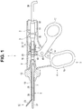
- Fig. 1 is a cross-sectional view showing an entire configuration of an ultrasound medical apparatus.
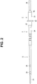
- Fig. 2 is a diagram showing a schematic configuration of an entire transducer unit.
- Fig. 3 is a perspective view showing a configuration of an ultrasound transducer.
- Fig. 4 is a side view showing the configuration of the ultrasound transducer.
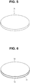
- Fig. 5 is a perspective view showing a piezoelectric single crystal wafer.
- Fig. 6 is a perspective view showing the piezoelectric single crystal wafer provided with base metal.
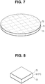
- Fig. 7 is a perspective view showing the piezoelectric single crystal wafer to be diced.
- Fig. 8 is a perspective view showing piezoelectric single crystal bodies cut out from the piezoelectric single crystal wafer.
- Fig. 1 is a cross-sectional view showing an entire configuration of an ultrasound medical apparatus.
- Fig. 2 is a diagram showing a schematic configuration of an entire transducer unit.
- Fig. 3 is a perspective view showing
- Fig. 9 is an exploded perspective view of the transducer unit including the ultrasound transducer.
- Fig. 10 is a cross-sectional view before flexible printed substrates are mounted on the ultrasound transducer of the transducer unit.
- Fig. 11 is a cross-sectional view after the flexible printed substrates are mounted on the ultrasound transducer of the transducer unit.
- Fig. 12 is a perspective view showing the transducer unit in which the FPCs are mounted on the ultrasound transducer.
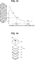
- Fig. 13 is a graph showing a relationship between thickness of bonding metals and thermal stress generated in the piezoelectric single crystal bodies due to a difference between a thermal expansion coefficient of mass materials and a thermal expansion coefficient of the piezoelectric single crystal bodies.
- Fig. 14 is an exploded perspective view showing an example of the bonding metals provided between the mass materials and the piezoelectric single crystal bodies.
- An ultrasound medical apparatus 1 shown in Fig. 1 is mainly provided with: a transducer unit 3 including an ultrasound transducer 2 configured to generate ultrasound vibration; and a handle unit 4 configured to use the ultrasound vibration to perform a coagulation/dissection treatment of a diseased part.
- the handle unit 4 includes an operation portion 5, an insertion sheath portion 8 including a long mantle tube 7, and a distal end treatment portion 30.
- a proximal end portion of the insertion sheath portion 8 is attached to the operation portion 5 and is rotatable about an axial direction.
- the distal end treatment portion 30 is provided on a distal end of the insertion sheath portion 8.
- the operation portion 5 of the handle unit 4 includes an operation portion main body 9, a fixed handle 10, a movable handle 11, and a rotation knob 12.
- the operation portion main body 9 is formed integrally with the fixed handle 10.
- a slit 13 for inserting the movable handle 11 is formed on a back side a connection portion of the operation portion main body 9 and the fixed handle 10. An upper part of the movable handle 11 is extended inside the operation portion main body 9 through the slit 13.
- a handle stopper 14 is fixed to an end portion of a lower side of the slit 13.
- the movable handle 11 is pivotably attached to the operation portion main body 9 through a handle support shaft 15. Along with an action of the movable handle 11 rotating about the handle support shaft 15, the movable handle 11 is configured to open and close relative to the fixed handle 10.
- a substantially U-shaped connection arm 16 is provided on an upper end portion of the movable handle 11.
- the insertion sheath portion 8 includes: the mantle tube 7; and an operation pipe 17 inserted into the mantle tube 7 and movable in an axis direction.
- a large diameter portion 18 with a diameter larger than a distal end side part is formed on a proximal end portion of the mantle tube 7.
- the rotation knob 12 is mounted around the large diameter portion 18.
- a ring-shaped slider 20 is provided on a circumference surface of an operation pipe 19 and is movable in an axis direction. Behind the slider 20, a fixation ring 22 is disposed through a coil spring (elastic member) 21.
- a proximal end portion of a grasping portion 23 is pivotably connected to a distal end portion of the operation pipe 19 through a working pin.
- the grasping portion 23 forms a treatment portion of the ultrasound medical apparatus 1 along with a distal end portion 31 of a probe 6.
- the grasping portion 23 is pushed and pulled in a front-back direction through the working pin.
- the grasping portion 23 is rotated counterclockwise about a fulcrum pin through the working pin.
- the grasping portion 23 rotates in a direction approaching the distal end portion 31 of the probe 6 (closing direction).
- living tissue can be grasped between the single-swing grasping portion 23 and the distal end portion 31 of the probe 6.
- the transducer unit 3 is assembled by integrating the ultrasound transducer 2 and the probe 6 that is a rod-shaped vibration transmission member configured to transmit the ultrasound vibration generated by the ultrasound transducer 2.
- a horn 32 configured to amplify the vibration amplitude generated by the ultrasound transducer is consecutively connected to the ultrasound transducer 2.
- the horn 32 is made of stainless steel, duralumin, or a titanium alloy such as 64Ti (Ti-6Al-4V).
- the horn 32 is formed in a conic shape with an external diameter decreasing toward the distal end side, and an outward flange 33 is disposed on a proximal end circumference portion.
- the shape of the horn 32 here is not limited to the conic shape, and the shape may be an index shape with the external diameter exponentially decreasing toward the distal end side or a step shape with the external diameter decreasing toward the distal end side in stages.
- the probe 6 includes a probe main body 34 made of a titanium alloy such as 64Ti (Ti-6Al-4V).
- the ultrasound transducer 2 consecutively connected to the horn 32 is disposed on a proximal end portion side of the probe main body 34.
- the transducer unit 3 is formed by integrating the probe 6 and the ultrasound transducer 2. Note that the probe main body 34 and the horn 32 are screwed in the probe 6, and the probe main body 34 and the horn 32 are connected.
- the ultrasound vibration generated by the ultrasound transducer 2 is amplified by the horn 32 and transmitted toward the distal end portion 31 of the probe 6.
- a treatment portion described later configured to treat the living tissue is disposed on the distal end portion 31 of the probe 6.
- Two rubber linings 35 are attached at intervals on a circumference surface of the probe main body 34, and the rubber linings 35 are formed in a ring shape by elastic members at several parts of node positions of the vibration in the middle of the axis direction.
- the rubber linings 35 are configured to prevent contact of the circumference surface of the probe main body 34 and the operation pipe 19 described later.
- the probe 6 as a transducer integrated probe is inserted into the operation pipe 19 at assembly of the insertion sheath portion 8.
- the rubber linings 35 prevent contact of the circumference surface of the probe main body 34 and the operation pipe 19.
- the ultrasound transducer 2 is electrically connected, through an electrical cable 36, to a power source apparatus main body not shown configured to supply electric current for generating the ultrasound vibration. Power is supplied from the power source apparatus main body to the ultrasound transducer 2 through wiring in the electrical cable 36, and the ultrasound transducer 2 is driven.
- the transducer unit 3 includes: the ultrasound transducer 2 configured to generate ultrasound vibration; the horn 32 configured to amplify the ultrasound vibration generated by the ultrasound transducer 2; and the probe 6 configured to transmit the amplified ultrasound vibration.
- the ultrasound transducer 2 as a stacked ultrasound vibration device of the present invention will be described.
- the ultrasound transducer 2 of the transducer unit 3 includes, in order from the distal end: the horn 32 connected by screwing or the like to the probe main body 34 that is one of vibration transmission members; a stacked transducer 41 in a rectangular shape (quadrangular prism shape) here, consecutively connected behind the horn 32; and a cover body 51 covering the stacked transducer 41 from a proximal end of the horn 32 to the electrical cable 36.
- the cover body 51 covering the stacked transducer 41 includes a bend preventing portion 52 covering wiring 36a and 36b of the electrical cable 36 electrically connected to two FPCs (flexible printed substrates) 47 and 48 that are energization members.
- the energization members are not limited to the FPCs 47 and 48, and the energization members may be simple metal lines.
- a front side of the stacked transducer 41 is bonded to a front mass 42, which is connected to the horn 32 by screwing or the like and made of a metal block body in a rectangular shape (quadrangular prism shape) here, and a back side is bonded to a back mass 43 made of a metal block body in a rectangular shape (quadrangular prism shape).
- the front mass 42 and the back mass 43 need to have a low absorptance of ultrasound vibration and a high strength, and therefore, the front mass 42 and the back mass 43 are formed by duralumin just like the horn 32.
- the front mass 42 and the back mass 43 may be stainless steel or titanium alloys such as 64Ti (Ti-6Al-4V).
- Lengths of the front mass 42 and the back mass 43 are designed such that the ultrasound transducer 2 has a desired resonance frequency.
- the stacked transducer 41 may sandwich an insulation member, made of a material with small attenuation for ultrasonic vibration, with the front mass 42 and with the back mass 43 respectively.
- the insulation member can be, for example, an insulating plate obtained by forming a ceramics material, such as alumina and silicon nitride, into a plate body in a rectangular shape (quadrangular prism shape).
- Piezoelectric elements formed from a non-lead single crystal material with a high Curie point are used for the stacked transducer 41, and a plurality of, four here, piezoelectric single crystal bodies 61 as piezoelectric single crystal chips that are the piezoelectric elements are stacked and arranged.
- positive side bonding metals 62 serving as positive electrode layers and negative side bonding metals 63 serving as negative electrode layers are alternately interposed as bonding metal layers formed from a non-lead solder described later that is a brazing material for bonding the four piezoelectric single crystal bodies 61 and the front mass 42 and the back mass 43.
- electrical contact portions of the FPCs 47 and 48 are electrically connected by a solder, a conductive paste, or the like to the positive side bonding metals 62 or the negative side bonding metals 63 provided between the piezoelectric single crystal bodies 61 and between the piezoelectric single crystal bodies 61 and the front mass 42 or the back mass 43.
- a piezoelectric material with a high Curie temperature (Curie point) and in which piezoelectric characteristics do not deteriorate even at a melting point of a bonding metal is used, and the ultrasound transducer 2 here is created from a piezoelectric single crystal wafer 71 (see Fig. 5 ) made of lithium niobate (LiNb03) as a single crystal material.
- a wafer with a crystal orientation called a 36 degree rotation Y cut is used for the piezoelectric single crystal wafer 71 to increase an electromechanical coupling coefficient of the piezoelectric element in a thickness direction.
- base metals 72 are formed on front and back surfaces of the piezoelectric single crystal wafer 71.
- the base metals 72 made of, for example, Ti/Ni/Au, Ti/Pt/Au, Cr/Ni/Au, or Cr/Ni/Pd/Au with excellent adhesion and wettability with respect to a non-lead solder are deposited on the front and back surfaces of the piezoelectric single crystal wafer 71 by vapor deposition, sputtering, plating, or the like.
- the piezoelectric single crystal wafer 71 provided with the base metals 72 is cut out and processed into a rectangular shape to form the piezoelectric single crystal body 61 as a piezoelectric body chip.
- the piezoelectric single crystal wafer 71 is cut out by a dicing blade with a thin thickness along cutting lines (virtual lines) shown in Fig. 7 , and a plurality of piezoelectric single crystal bodies 61 as piezoelectric body chips in a rectangular shape as shown in Fig. 8 are fabricated.
- Such a configuration allows manufacturing a plurality of piezoelectric single crystal bodies 61 inexpensively.
- a desired number of piezoelectric single crystal bodies 61 the number of piezoelectric signal crystal bodies being four in this embodiment, according to specifications of the ultrasound transducer 2 are stacked.
- the front mass 42 and the back mass 43 as mass materials are bonded so as to sandwich both ends of the stacked transducer 41 as a stacked body made of the four piezoelectric single crystal bodies 61.
- first brazing materials 73 that are non-lead solders are provided as first bonding materials between the base metals 72 of the four piezoelectric single crystal bodies 61.
- the three first brazing materials 73 interposed between the four piezoelectric single crystal bodies 61 are set to a minimum thickness d1 necessary to bond the piezoelectric single crystal bodies 61 that are similar materials. Note that screen printing or a ribbon format (solder pellet) is used to dispose the first brazing materials 73 on one of the base metals 72 of the piezoelectric single crystal wafers 71.
- the front mass 42 and the back mass 43 that are metal blocks are bonded so as to sandwich both ends of the stacked transducer 41 stacked the four piezoelectric single crystal bodies 61 and the three first brazing materials 73.
- second brazing materials 76 that are non-lead solders are provided as second bonding materials between the piezoelectric single crystal bodies 61 positioned at both ends and the front mass 42 and the back mass 43.
- the second brazing material 76 interposed between the piezoelectric single crystal body 61 and the front mass 42 or the back mass 43 that are dissimilar materials is set to a thickness d2 thicker than the thickness d1 of the first brazing materials 73 as shown in Fig. 10 .
- screen printing or a ribbon format is also used to dispose the second brazing materials 76 on the base metals 72 of the piezoelectric single crystal bodies 61 or on one surface of the front mass 42 and the back mass 43, just like the first brazing materials 73.
- the four piezoelectric single crystal bodies 61, the front mass 42, and the back mass 43 are heated to a melting temperature of the first brazing materials 73 and the second brazing materials 76 for mutual bonding and are slowly cooled. In this way, the four piezoelectric single crystal bodies 61, the front mass 42, and the back mass 43 are stacked and mutually bonded by the first brazing materials 73 and the second brazing materials 76.
- a pressure can be applied for compression in a stacked direction as necessary.
- the four piezoelectric single crystal bodies 61, the front mass 42, and the back mass 43 are stacked, and the ultrasound transducer 2 bonded by the first brazing materials 73 or the second brazing materials 76 is completed.
- the base metals 72 deposited on the four piezoelectric single crystal bodies 61 are included, and the positive side bonding metals 62 or the negative side bonding metals 63 are formed by the first brazing materials 73 and the second brazing materials 76.
- a screw hole 42a with a tap is processed at a center of one end surface of the front mass 42.
- a screw portion 32a integrally formed with the horn 32 is screwed to the screw hole 42a, and the horn 32 and the front mass 42 are screwed.
- the two FPCs 47 and 48 that are energization members are mounted on the ultrasound transducer 2.
- the positive side bonding metals 62 and the negative side bonding metals 63 of the ultrasound transducer 2 are electrically connected to electrical contacts of the FPCs 47 and 48 through electric connection portions 49 formed by using a solder, a conductive paste, or the like.
- the electrical contacts of the FPCs 47 and 48 come into contact with outer surfaces of the positive side bonding metals 62 and the negative side bonding metals 63 through the electric connection portions 49, and the FPCs 47 and 48 are fixed to the stacked transducer 41.
- FIGs. 10 to 12 illustrate a state that the horn 32 and the front mass 42 are screwed
- the horn 32 and the front mass 42 can be bonded by screwing before or after the installation of the FPCs 47 and 48 on the ultrasound transducer 2.
- the wiring 36a of the electrical cable 36, the FPC 47, the electric connection portions 49, and the positive electrode side metals 62 are electrically connected on a positive electrode side.
- the wiring 36b of the electrical cable 36, the FPC 48, the electric connection portions 49, and the negative electrode metals 63 are electrically connected on a negative electrode side.
- the drive signal is applied to the four piezoelectric single crystal bodies 61 through the positive side bonding metals 62 and returned from the negative side bonding metals 63.
- exposed surface parts of the positive side bonding metals 62, the negative side bonding metals 63, and the electric connection portion 49 may be covered by an insulating body, such as a resin, to prevent generation of an unnecessary electrical connection that causes a failure, or the FPCs 47 and 48 may be fixed by an adhesive to the positive side bonding metals 62 and the negative side bonding metals 63 in order to reinforce the mechanical fixation of the FPCs 47 and 48. Furthermore, the FPCs 47 and 48 may be fixed by an adhesive on surfaces of side portions of the four piezoelectric single crystal bodies 61.
- the front mass 42, the four piezoelectric single crystal bodies 61, and the back mass 43 in order from the distal end are bonded and integrated by the first brazing materials 73 and the second brazing materials 76 serving as bonding metal layers and serving as the positive side bonding metals 62 and the negative side bonding metals 63.
- the drive signal is applied from the FPCs 47 and 48 provided on the side face of the stacked body to the positive side bonding metals 62 through the electric connection portions 49 and is returned by the negative side bonding metals 63 to thereby generate ultrasound vibration of the entire ultrasound transducer 2.
- the parts for bonding the piezoelectric single crystal bodies 61 of the stacked transducer 41 in the ultrasound transducer 2 are similar materials, lithium niobate (LiNbO3) here, and therefore thermal stress generated in the four piezoelectric single crystal bodies 61 due to temperature changes during the bonding and during the drive is small.
- parts for bonding the piezoelectric single crystal bodies 61 to the front mass 42 and the back mass 43 are bonding of dissimilar materials. Therefore, a difference between two different materials, a thermal expansion coefficient (8 to 15 ⁇ 10 -6 [1/°C]) of lithium niobate (LiNb03) and a thermal expansion coefficient (24 ⁇ 10 -6 [1/°C]) of duralumin here, generates thermal stress in the two piezoelectric single crystal bodies 61 at both ends bonded to the front mass 42 or the back mass 43, and the thermal stress is greater than that at the similar material bonding portion due to temperature changes during bonding and during drive.
- a thermal expansion coefficient (8 to 15 ⁇ 10 -6 [1/°C]) of lithium niobate (LiNb03) and a thermal expansion coefficient (24 ⁇ 10 -6 [1/°C]) of duralumin generates thermal stress in the two piezoelectric single crystal bodies 61 at both ends bonded to the front mass 42 or the back mass 43, and the
- first brazing materials 73 and the second brazing materials 76 forming the positive side bonding metals 62 or the negative side bonding metals 63 are soft materials with Young's moduli (elastic constants) smaller than those of the piezoelectric single crystal bodies 61, the front mass 42, and the back mass 43.
- first brazing materials 73 or the second brazing materials 76 operates to absorb the thermal stress generated in the piezoelectric single crystal bodies 61, absorptance of the ultrasound generated in the ultrasound transducer 2 is also large.
- the thicknesses of the first brazing materials 73 and the second brazing materials 76 are too thick, characteristics of the ultrasound transducer 2 as a Langevin transducer are deteriorated.
- the thickness of the first brazing materials 73 as similar material bonding portions for the bonding between the four piezoelectric single crystal bodies 61 as similar materials is set to the minimum thickness d1 necessary for the bonding of the four piezoelectric single crystal bodies 61, and the thickness d2 of the second brazing materials 76 as dissimilar material bonding portions with relatively large thermal stress is thicker than the thickness d1 of the first brazing materials 73 (d1 ⁇ d2).
- the Young's modulus (elastic constant) of the second brazing materials 76 is smaller than the Young's moduli of the piezoelectric single crystal bodies 61, the front mass 42, and the back mass 43, and the second brazing materials 76 are soft. Therefore, the second brazing materials 76 are thick in the ultrasound transducer 2, and the second brazing materials 76 function as stress buffer layers for bonding the piezoelectric single crystal bodies 61 to the front mass 42 or the back mass 43 that are dissimilar material bonding portions.
- the stress buffer layers have a large thickness, a loss of ultrasound generated in the ultrasound transducer 2 by the stress buffer layer is larger than that by the piezoelectric single crystal bodies 61 made of duralumin and lithium niobate (LiNb03) used for the front mass 42 and the back mass 43.
- volume of the first brazing materials 73 and the second brazing materials 76 be as small as possible. That is, when the volumes of the first brazing materials 73 and the second brazing materials 76 are small, the loss of the generated ultrasound is small in the entire ultrasound transducer 2.
- the first brazing materials 73 with the minimum thickness d1 necessary for the bonding portions between the four piezoelectric single crystal bodies 61 with almost no thermal stress are used in the ultrasound transducer 2 of the present embodiment to prevent the reduction of performance (reduction of Q value), and the second brazing materials 76 with the thickness d2 thicker than that of the first brazing materials 73 are used for the bonding portions of the two piezoelectric single crystal bodies 61 provided at both ends with notable thermal stress due to the difference in the thermal expansion coefficients and the front mass 42 or the back mass 43. In this way, the thermal stress is reduced, and a crack of the two piezoelectric single crystal bodies 61 provided on the dissimilar material bonding portions is prevented.
- the ultrasound transducer 2 can prevent the degradation of performance of the entire ultrasound transducer 2 while preventing a crack of the two piezoelectric single crystal bodies 61 provided at both ends bonded to the front mass 42 or the back mass 43.
- a Sn-Ag-Cu-based solder with a thermal expansion coefficient between the thermal expansion coefficient of the piezoelectric single crystal bodies 61 made of lithium niobate (LiNbO3) and the thermal expansion coefficient of the front mass 42 and the back mass 43 made of duralumin is used for the first brazing materials 73 and the second brazing materials 76, for example.
- the thermal expansion coefficient of the Sn-Ag-Cu-based solder used for the first brazing materials 73 and the second brazing materials 76 is 21 ⁇ 10 -6 [1/°C] which is greater than the thermal expansion coefficient (8 to 15 ⁇ 10 -6 [1/°C]) of lithium niobate (LiNbO3) and smaller than the thermal expansion coefficient (24 ⁇ 10 -6 [1/°C]) of duralumin.
- the second brazing materials 76 made of the Sn-Ag-Cu-based solder that is a bonding material of the two piezoelectric single crystal bodies 61 provided at both ends and the front mass 42 and the back mass 43 particularly play a role of absorbing the difference between the thermal expansion coefficient of the two piezoelectric single crystal bodies 61 provided at both ends and the thermal expansion coefficient of the front mass 42 and the back mass 43.
- the stress on the piezoelectric single crystal bodies 61 is reduced, and generation of a crack inside the piezoelectric single crystal bodies 61 is prevented.
- the thermal expansion coefficient of the second brazing materials 76 be between the thermal expansion coefficients of lithium niobate (LiNbO3) and duralumin, and other than the Su-Ag-Cu-based solder, a Sn-based solder, a Sn-Ag-based solder, or a Sn-Cu-based solder may be used, for example.
- the thermal stress generated in the piezoelectric single crystal bodies 61 due to the difference between the thermal expansion coefficient of the piezoelectric single crystal bodies 61 and the thermal expansion coefficient of the front mass 42 and the back mass 43 is generated as indicated by a curve as shown in Fig. 13 according to the thickness of the second brazing materials 76.
- P1 on the curve of Fig. 13 denotes a point in which the piezoelectric single crystal bodies 61 are cracked due to thermal stress ⁇ 1 generated by the difference between the thermal expansion coefficient of the piezoelectric single crystal bodies 61 and the thermal expansion coefficient of the front mass 42 and the back mass 43.
- the thickness d2 of the second brazing materials 76 as bonding metals is set between a thickness d2min indicated by P2 based on a predetermined safety factor (for example, half the thermal stress ⁇ 1) that does not cause a crack even if thermal stress ⁇ 2 is generated in the piezoelectric single crystal bodies 61 and a thickness d2max indicated by P3 with which there is almost no change in thermal stress ⁇ 3 generated in the piezoelectric single crystal bodies 61 even if the thickness of the brazing materials 76 is changed.
- a predetermined safety factor for example, half the thermal stress ⁇ 1
- the thermal stress ⁇ 3 generated in the piezoelectric single crystal bodies 61 due to the difference between the thermal expansion coefficient of the piezoelectric single crystal bodies 61 and the thermal expansion coefficient of the front mass 42 and the back mass 43 does not change. Therefore, if the thickness d2 is thicker than the thickness d2max, the performance of the ultrasound transducer 2 is further reduced.
- the thickness d2 of the second brazing materials 76 it is most preferable to set the thickness d2 of the second brazing materials 76 to the thickness d2max if the loss of ultrasound generated in the ultrasound transducer 2 is within a permissible range of specifications. That is, an upper limit of the thickness d2 of the second brazing materials 76 is d2max that is a smallest thickness with which the thermal stress ⁇ 3 generated in the piezoelectric single crystal bodies 61 does not change.
- the thickness d2 of the second brazing materials 76 can be set in screen printing, or a thick solder pellet can be prepared. Therefore, the ultrasound transducer 2 can be realized inexpensively without an extra step or without a change in the process or the like.
- the ribbon format (solder pellet) is used for the first brazing materials 73 and the second brazing materials 76
- a plurality of, two here, first brazing materials 73 can be placed on each other to form the second brazing material 76 as shown for example in Fig. 14 .
- materials with different thickness do not have to be prepared. That is, the thickness of the second brazing materials 76 can be set to the thickness d2 that is an integral multiple of the first brazing materials 73, and therefore the cost can be further reduced.
- the ultrasound transducer 2 has a rectangular block shape that can be most inexpensively manufactured in the example described above, the shape is not limited to this.
- the shapes of the members may be columnar shapes.
- the ultrasound transducer 2 that is a stacked ultrasound vibration device of the present embodiment and the ultrasound medical apparatus 1 including the ultrasound transducer 2 can be inexpensively manufactured, and damage or the like of piezoelectric bodies due to stress caused by a difference between a thermal expansion coefficient of metal blocks as mass materials and a thermal expansion coefficient of the piezoelectric bodies can be prevented.
- the embodiment includes inventions of various phases, and various inventions can be extracted based on appropriate combinations of a plurality of disclosed constituent elements.
- the configuration after the removal of the constituent elements can be extracted as an invention.
Landscapes
- Engineering & Computer Science (AREA)
- Health & Medical Sciences (AREA)
- Mechanical Engineering (AREA)
- Surgery (AREA)
- Life Sciences & Earth Sciences (AREA)
- Manufacturing & Machinery (AREA)
- General Health & Medical Sciences (AREA)
- Nuclear Medicine, Radiotherapy & Molecular Imaging (AREA)
- Heart & Thoracic Surgery (AREA)
- Medical Informatics (AREA)
- Molecular Biology (AREA)
- Animal Behavior & Ethology (AREA)
- Veterinary Medicine (AREA)
- Public Health (AREA)
- Biomedical Technology (AREA)
- Dentistry (AREA)
- Surgical Instruments (AREA)
- Apparatuses For Generation Of Mechanical Vibrations (AREA)
- Transducers For Ultrasonic Waves (AREA)
- Piezo-Electric Transducers For Audible Bands (AREA)
Abstract
Description
- The present invention relates to a stacked ultrasound vibration device configured to excite ultrasound vibration and an ultrasound medical apparatus including the stacked ultrasound vibration device.
- Among ultrasound treatment instruments configured to utilize ultrasound vibration to perform a coagulation/dissection treatment of living tissue, there is an ultrasound treatment instrument including an ultrasound vibrator using a piezoelectric transducer as an ultrasound vibration source in a handpiece.
- Among the ultrasound vibrators, there is an ultrasound vibrator including piezoelectric elements configured to convert an electrical signal to mechanical vibration, and the piezoelectric elements are sandwiched between two block-shaped metal members serving as a front mass or a back mass. The piezoelectric elements and the metal members are integrated by some kind of method such as adhesion, and they integrally vibrate. Such an ultrasound transducer is called a Langevin transducer.
- An example of a known method of integrating the piezoelectric elements and the metal members in the Langevin transducer includes a bolt clamped Langevin transducer in which piezoelectric elements are placed between two metal members. In the bolt clamped Langevin transducer, the piezoelectric elements and the metal members are firmly fastened by a bolt, and the entire piezoelectric elements and metal members integrally vibrate.
- In general, lead zirconate titanate (PZT, Pb (ZrX, Ti1-X) 03) is used for the piezoelectric elements used in the bolt clamped Langevin transducer. A shape of the piezoelectric elements is processed into a ring shape, and the bolt is pushed and inserted into the inside.
- Productivity and electromechanical conversion efficiency of PZT are high, and PZT has good characteristics as a piezoelectric material. Therefore, PZT is used in various fields of ultrasound transducers, actuators, and the like for a long time.
- However, lead is used in PZT, and use of a non-lead piezoelectric material without using lead has been desired in recent years from the viewpoint of preventing adverse effects on the environment. An example of a known non-lead piezoelectric material with high electromechanical conversion efficiency includes lithium niobate (LiNbO3) piezoelectric single crystals.
- A method of placing piezoelectric elements between metal blocks and integrally bonding the piezoelectric elements and the metal blocks has been conventionally known as a configuration for inexpensively realizing a Langevin transducer using lithium niobate. Particularly, when a brazing material such as a solder is used to bond the metal blocks and the piezoelectric elements without using an adhesive, the Langevin transducer can obtain better vibration characteristics than those of the adhesive.
- However, a high temperature process is generally necessary to bond the metal blocks and the piezoelectric elements by a brazing material such as a solder. There is a problem that the piezoelectric elements with piezoelectric single crystals crack due to thermal stress at dissimilar material bonding portions that are parts where the metal blocks and the piezoelectric elements are bonded.
- An example of a disclosed technique for solving the problem includes an ultrasound vibrator of Japanese Patent Application Laid-Open Publication No.
2008-128875 - However, there is a problem that a processing step is necessary for the metal block surface in the conventional ultrasound vibrator disclosed in Japanese Patent Application Laid-Open Publication No.
2008-128875 - That is, the conventional ultrasound vibrator is provided with structures, such as grooves and depressions, on the metal block surface in order to absorb thermal stress generated at bonding portions between dissimilar materials when the metal blocks and the piezoelectric elements are bonded by adhesion or to absorb stress generated by hardening and shrinking of the adhesive. Therefore, there is a problem that extra processing is necessary, and this increases the cost.
- Furthermore, when a thermosetting adhesive is used to bond and fix the piezoelectric transducer and the metal blocks in the conventional ultrasound vibrator, the vicinity of the bonding surface is heated to cure the adhesive. As a result, after the curing of the adhesive in the conventional ultrasound vibrator, a difference between thermal expansion coefficients of the piezoelectric transducer and the metal blocks may lead to generation of a shear strain equivalent to a temperature difference between adhering temperature and normal temperature.
- There is also a problem that residual stress always exists on the bonding surface of the piezoelectric transducer and the metal blocks, and this leads to generation of a crack inside the piezoelectric transducer.
- The present invention has been made in view of the circumstances, and an object of the present invention is to provide a stacked ultrasound vibration device and an ultrasound medical apparatus that can be inexpensively manufactured and that prevent damage or the like of a piezoelectric transducer due to stress caused by a difference between a thermal expansion coefficient of metal blocks as mass materials and a thermal expansion coefficient of piezoelectric bodies.
- An aspect of the present invention provides a stacked ultrasound vibration device comprising a plurality of piezoelectric bodies and mass material, wherein the plurality of piezoelectric bodies are bonded each other as similar material bonding portion by a first metal bonding layer with a first thickness, wherein the piezoelectric body and the mass material are bonded as dissimilar material bonding portion by a second metal bonding layer with a second thickness thicker than the first thickness, and wherein the first metal bonding layer and the second metal bonding layer comprise brazing material whose elastic constant is smaller than elastic constants of the plurality of piezoelectric bodies and the mass material.
- An aspect of the present invention provides an ultrasound medical apparatus including: the stacked ultrasound vibration device comprising a plurality of piezoelectric bodies and mass material, wherein the plurality of piezoelectric bodies are bonded each other as similar material bonding portion by a first metal bonding layer with a first thickness, wherein the piezoelectric body and the mass material are bonded as dissimilar material bonding portion by a second metal bonding layer with a second thickness thicker than the first thickness, and wherein the first metal bonding layer and the second metal bonding layer comprise brazing material whose elastic constant is smaller than elastic constants of the plurality of piezoelectric bodies and the mass material; and a probe distal end portion configured to receive ultrasound vibration generated by the stacked ultrasound vibration device to treat living tissue.
- The present invention can provide a stacked ultrasound vibration device and an ultrasound medical apparatus that can be inexpensively manufactured and prevent damage or the like of a piezoelectric body due to stress caused by a difference between a thermal expansion coefficient of metal blocks as mass materials and a thermal expansion coefficient of piezoelectric bodies.
-
-
Fig. 1 is a cross-sectional view showing an entire configuration of an ultrasound medical apparatus according to an aspect of the present invention; -
Fig. 2 is a diagram showing a schematic configuration of an entire transducer unit according to the aspect of the present invention; -
Fig. 3 is a perspective view showing a configuration of an ultrasound transducer according to the aspect of the present invention; -
Fig. 4 is a side view showing the configuration of the ultrasound transducer according to the aspect of the present invention; -
Fig. 5 is a perspective view showing a piezoelectric single crystal wafer according to the aspect of the present invention; -
Fig. 6 is a perspective view showing the piezoelectric single crystal wafer provided with base metals according to the aspect of the present invention; -
Fig. 7 is a perspective view showing the piezoelectric single crystal wafer to be diced according to the aspect of the present invention; -
Fig. 8 is a perspective view showing piezoelectric single crystal bodies cut out from the piezoelectric single crystal wafer according to the aspect of the present invention; -
Fig. 9 is an exploded perspective view of the transducer unit including the ultrasound transducer according to the aspect of the present invention; -
Fig. 10 is a cross-sectional view before flexible printed substrates are mounted on the ultrasound transducer of the transducer unit according to the aspect of the present invention; -
Fig. 11 is a cross-sectional view after the flexible printed substrates are mounted on the ultrasound transducer of the transducer unit according to the aspect of the present invention; -
Fig. 12 is a perspective view showing the transducer unit in which the FPCs are mounted on the ultrasound transducer according to the aspect of the present invention; -
Fig. 13 is a graph showing a relationship between thickness of bonding metals and thermal stress generated in the piezoelectric single crystal bodies due to a difference between a thermal expansion coefficient of mass materials and a thermal expansion coefficient of the piezoelectric single crystal bodies according to the aspect of the present invention; and -
Fig. 14 is an exploded perspective view showing an example of the bonding metals provided between the mass materials and the piezoelectric single crystal bodies according to the aspect of the present invention. - Hereinafter, the present invention will be described with reference to the drawings. Note that in the following description, the drawings based on respective embodiments are schematic drawings, and a relationship between thickness and width of each part, a ratio of the thickness of respective parts, and the like are different from the reality. The relationship or the ratio of respective dimensions between the drawings may also be different in some parts of the drawings.
- First, an embodiment of an ultrasound medical apparatus including a stacked ultrasound vibration device configured to excite ultrasound vibration according to an aspect of the present invention will be described with reference to the drawings.
-
Fig. 1 is a cross-sectional view showing an entire configuration of an ultrasound medical apparatus.Fig. 2 is a diagram showing a schematic configuration of an entire transducer unit.Fig. 3 is a perspective view showing a configuration of an ultrasound transducer.Fig. 4 is a side view showing the configuration of the ultrasound transducer.Fig. 5 is a perspective view showing a piezoelectric single crystal wafer.Fig. 6 is a perspective view showing the piezoelectric single crystal wafer provided with base metal.Fig. 7 is a perspective view showing the piezoelectric single crystal wafer to be diced.Fig. 8 is a perspective view showing piezoelectric single crystal bodies cut out from the piezoelectric single crystal wafer.Fig. 9 is an exploded perspective view of the transducer unit including the ultrasound transducer.Fig. 10 is a cross-sectional view before flexible printed substrates are mounted on the ultrasound transducer of the transducer unit.Fig. 11 is a cross-sectional view after the flexible printed substrates are mounted on the ultrasound transducer of the transducer unit.Fig. 12 is a perspective view showing the transducer unit in which the FPCs are mounted on the ultrasound transducer.Fig. 13 is a graph showing a relationship between thickness of bonding metals and thermal stress generated in the piezoelectric single crystal bodies due to a difference between a thermal expansion coefficient of mass materials and a thermal expansion coefficient of the piezoelectric single crystal bodies.Fig. 14 is an exploded perspective view showing an example of the bonding metals provided between the mass materials and the piezoelectric single crystal bodies. - An ultrasound
medical apparatus 1 shown inFig. 1 is mainly provided with: atransducer unit 3 including anultrasound transducer 2 configured to generate ultrasound vibration; and a handle unit 4 configured to use the ultrasound vibration to perform a coagulation/dissection treatment of a diseased part. - The handle unit 4 includes an
operation portion 5, aninsertion sheath portion 8 including along mantle tube 7, and a distalend treatment portion 30. A proximal end portion of theinsertion sheath portion 8 is attached to theoperation portion 5 and is rotatable about an axial direction. - The distal
end treatment portion 30 is provided on a distal end of theinsertion sheath portion 8. Theoperation portion 5 of the handle unit 4 includes an operation portionmain body 9, a fixedhandle 10, amovable handle 11, and arotation knob 12. The operation portionmain body 9 is formed integrally with the fixedhandle 10. - A slit 13 for inserting the
movable handle 11 is formed on a back side a connection portion of the operation portionmain body 9 and the fixedhandle 10. An upper part of themovable handle 11 is extended inside the operation portionmain body 9 through theslit 13. - A
handle stopper 14 is fixed to an end portion of a lower side of theslit 13. Themovable handle 11 is pivotably attached to the operation portionmain body 9 through ahandle support shaft 15. Along with an action of themovable handle 11 rotating about thehandle support shaft 15, themovable handle 11 is configured to open and close relative to the fixedhandle 10. - A substantially
U-shaped connection arm 16 is provided on an upper end portion of themovable handle 11. Theinsertion sheath portion 8 includes: themantle tube 7; and anoperation pipe 17 inserted into themantle tube 7 and movable in an axis direction. - A
large diameter portion 18 with a diameter larger than a distal end side part is formed on a proximal end portion of themantle tube 7. Therotation knob 12 is mounted around thelarge diameter portion 18. - A ring-shaped
slider 20 is provided on a circumference surface of anoperation pipe 19 and is movable in an axis direction. Behind theslider 20, afixation ring 22 is disposed through a coil spring (elastic member) 21. - Furthermore, a proximal end portion of a grasping
portion 23 is pivotably connected to a distal end portion of theoperation pipe 19 through a working pin. The graspingportion 23 forms a treatment portion of the ultrasoundmedical apparatus 1 along with adistal end portion 31 of aprobe 6. At an action of theoperation pipe 19 moving in the axis direction, the graspingportion 23 is pushed and pulled in a front-back direction through the working pin. - In this case, at an action of the
operation pipe 19 moved and operated toward a hand side, the graspingportion 23 is rotated counterclockwise about a fulcrum pin through the working pin. - As a result, the grasping
portion 23 rotates in a direction approaching thedistal end portion 31 of the probe 6 (closing direction). In this case, living tissue can be grasped between the single-swing grasping portion 23 and thedistal end portion 31 of theprobe 6. - In a state that the living tissue is grasped, power is supplied from an ultrasound power source to the
ultrasound transducer 2 to vibrate theultrasound transducer 2. The ultrasound vibration is transmitted to thedistal end portion 31 of theprobe 6. The ultrasound vibration is used to perform a coagulation/dissection treatment of the living tissue grasped between the graspingportion 23 and thedistal end portion 31 of theprobe 6. - Here, the
transducer unit 3 will be described. - As shown in
Fig. 2 , thetransducer unit 3 is assembled by integrating theultrasound transducer 2 and theprobe 6 that is a rod-shaped vibration transmission member configured to transmit the ultrasound vibration generated by theultrasound transducer 2. - A
horn 32 configured to amplify the vibration amplitude generated by the ultrasound transducer is consecutively connected to theultrasound transducer 2. Thehorn 32 is made of stainless steel, duralumin, or a titanium alloy such as 64Ti (Ti-6Al-4V). - The
horn 32 is formed in a conic shape with an external diameter decreasing toward the distal end side, and anoutward flange 33 is disposed on a proximal end circumference portion. Note that the shape of thehorn 32 here is not limited to the conic shape, and the shape may be an index shape with the external diameter exponentially decreasing toward the distal end side or a step shape with the external diameter decreasing toward the distal end side in stages. - The
probe 6 includes a probemain body 34 made of a titanium alloy such as 64Ti (Ti-6Al-4V). Theultrasound transducer 2 consecutively connected to thehorn 32 is disposed on a proximal end portion side of the probemain body 34. - In this way, the
transducer unit 3 is formed by integrating theprobe 6 and theultrasound transducer 2. Note that the probemain body 34 and thehorn 32 are screwed in theprobe 6, and the probemain body 34 and thehorn 32 are connected. - The ultrasound vibration generated by the
ultrasound transducer 2 is amplified by thehorn 32 and transmitted toward thedistal end portion 31 of theprobe 6. A treatment portion described later configured to treat the living tissue is disposed on thedistal end portion 31 of theprobe 6. - Two
rubber linings 35 are attached at intervals on a circumference surface of the probemain body 34, and therubber linings 35 are formed in a ring shape by elastic members at several parts of node positions of the vibration in the middle of the axis direction. Therubber linings 35 are configured to prevent contact of the circumference surface of the probemain body 34 and theoperation pipe 19 described later. - That is, the
probe 6 as a transducer integrated probe is inserted into theoperation pipe 19 at assembly of theinsertion sheath portion 8. In this case, therubber linings 35 prevent contact of the circumference surface of the probemain body 34 and theoperation pipe 19. - The
ultrasound transducer 2 is electrically connected, through anelectrical cable 36, to a power source apparatus main body not shown configured to supply electric current for generating the ultrasound vibration. Power is supplied from the power source apparatus main body to theultrasound transducer 2 through wiring in theelectrical cable 36, and theultrasound transducer 2 is driven. - As described above, the
transducer unit 3 includes: theultrasound transducer 2 configured to generate ultrasound vibration; thehorn 32 configured to amplify the ultrasound vibration generated by theultrasound transducer 2; and theprobe 6 configured to transmit the amplified ultrasound vibration. - Here, the
ultrasound transducer 2 as a stacked ultrasound vibration device of the present invention will be described. - As shown in
Figs. 3 and 4 , theultrasound transducer 2 of thetransducer unit 3 includes, in order from the distal end: thehorn 32 connected by screwing or the like to the probemain body 34 that is one of vibration transmission members; astacked transducer 41 in a rectangular shape (quadrangular prism shape) here, consecutively connected behind thehorn 32; and acover body 51 covering the stackedtransducer 41 from a proximal end of thehorn 32 to theelectrical cable 36. - On a proximal end part, the
cover body 51 covering the stackedtransducer 41 includes abend preventing portion 52 coveringwiring electrical cable 36 electrically connected to two FPCs (flexible printed substrates) 47 and 48 that are energization members. Note that the energization members are not limited to theFPCs - A front side of the stacked
transducer 41 is bonded to afront mass 42, which is connected to thehorn 32 by screwing or the like and made of a metal block body in a rectangular shape (quadrangular prism shape) here, and a back side is bonded to aback mass 43 made of a metal block body in a rectangular shape (quadrangular prism shape). - Note that the
front mass 42 and theback mass 43 need to have a low absorptance of ultrasound vibration and a high strength, and therefore, thefront mass 42 and theback mass 43 are formed by duralumin just like thehorn 32. Thefront mass 42 and theback mass 43 may be stainless steel or titanium alloys such as 64Ti (Ti-6Al-4V). - Lengths of the
front mass 42 and theback mass 43 are designed such that theultrasound transducer 2 has a desired resonance frequency. - Furthermore, the stacked
transducer 41 may sandwich an insulation member, made of a material with small attenuation for ultrasonic vibration, with thefront mass 42 and with theback mass 43 respectively. The insulation member can be, for example, an insulating plate obtained by forming a ceramics material, such as alumina and silicon nitride, into a plate body in a rectangular shape (quadrangular prism shape). - In this way, by providing the insulating member, damage or the like of the stacked
transducer 41 caused by a high frequency electrical signal from a treatment instrument is prevented even if the ultrasoundmedical apparatus 1 shown inFig. 1 is used together with the treatment instrument, such as a medical high frequency surgical knife, configured to perform a treatment or the like by using a high frequency electrical signal. - Piezoelectric elements formed from a non-lead single crystal material with a high Curie point are used for the stacked
transducer 41, and a plurality of, four here, piezoelectricsingle crystal bodies 61 as piezoelectric single crystal chips that are the piezoelectric elements are stacked and arranged. - Between the four piezoelectric
single crystal bodies 61 and thefront mass 42 and theback mass 43, positiveside bonding metals 62 serving as positive electrode layers and negativeside bonding metals 63 serving as negative electrode layers are alternately interposed as bonding metal layers formed from a non-lead solder described later that is a brazing material for bonding the four piezoelectricsingle crystal bodies 61 and thefront mass 42 and theback mass 43. - Note that in the stacked
transducer 41, electrical contact portions of theFPCs side bonding metals 62 or the negativeside bonding metals 63 provided between the piezoelectricsingle crystal bodies 61 and between the piezoelectricsingle crystal bodies 61 and thefront mass 42 or theback mass 43. - Next, a manufacturing method of the
ultrasound transducer 2 described above will be described in detail. - First, a piezoelectric material with a high Curie temperature (Curie point) and in which piezoelectric characteristics do not deteriorate even at a melting point of a bonding metal is used, and the
ultrasound transducer 2 here is created from a piezoelectric single crystal wafer 71 (seeFig. 5 ) made of lithium niobate (LiNb03) as a single crystal material. - Note that a wafer with a crystal orientation called a 36 degree rotation Y cut is used for the piezoelectric
single crystal wafer 71 to increase an electromechanical coupling coefficient of the piezoelectric element in a thickness direction. - First, as shown in
Figs. 5 and 6 ,base metals 72 are formed on front and back surfaces of the piezoelectricsingle crystal wafer 71. - More specifically, the
base metals 72 made of, for example, Ti/Ni/Au, Ti/Pt/Au, Cr/Ni/Au, or Cr/Ni/Pd/Au with excellent adhesion and wettability with respect to a non-lead solder are deposited on the front and back surfaces of the piezoelectricsingle crystal wafer 71 by vapor deposition, sputtering, plating, or the like. - Next, as shown in
Figs. 7 and 8 , the piezoelectricsingle crystal wafer 71 provided with thebase metals 72 is cut out and processed into a rectangular shape to form the piezoelectricsingle crystal body 61 as a piezoelectric body chip. - More specifically, the piezoelectric
single crystal wafer 71 is cut out by a dicing blade with a thin thickness along cutting lines (virtual lines) shown inFig. 7 , and a plurality of piezoelectricsingle crystal bodies 61 as piezoelectric body chips in a rectangular shape as shown inFig. 8 are fabricated. Such a configuration allows manufacturing a plurality of piezoelectricsingle crystal bodies 61 inexpensively. - Next, as shown in
Fig. 9 , a desired number of piezoelectricsingle crystal bodies 61, the number of piezoelectric signal crystal bodies being four in this embodiment, according to specifications of theultrasound transducer 2 are stacked. Thefront mass 42 and theback mass 43 as mass materials are bonded so as to sandwich both ends of the stackedtransducer 41 as a stacked body made of the four piezoelectricsingle crystal bodies 61. - More specifically,
first brazing materials 73 that are non-lead solders are provided as first bonding materials between thebase metals 72 of the four piezoelectricsingle crystal bodies 61. - The three
first brazing materials 73 interposed between the four piezoelectricsingle crystal bodies 61 are set to a minimum thickness d1 necessary to bond the piezoelectricsingle crystal bodies 61 that are similar materials. Note that screen printing or a ribbon format (solder pellet) is used to dispose thefirst brazing materials 73 on one of thebase metals 72 of the piezoelectricsingle crystal wafers 71. - The
front mass 42 and theback mass 43 that are metal blocks are bonded so as to sandwich both ends of the stackedtransducer 41 stacked the four piezoelectricsingle crystal bodies 61 and the threefirst brazing materials 73. - Here,
second brazing materials 76 that are non-lead solders are provided as second bonding materials between the piezoelectricsingle crystal bodies 61 positioned at both ends and thefront mass 42 and theback mass 43. - The
second brazing material 76 interposed between the piezoelectricsingle crystal body 61 and thefront mass 42 or theback mass 43 that are dissimilar materials is set to a thickness d2 thicker than the thickness d1 of thefirst brazing materials 73 as shown inFig. 10 . - Note that screen printing or a ribbon format (solder pellet) is also used to dispose the
second brazing materials 76 on thebase metals 72 of the piezoelectricsingle crystal bodies 61 or on one surface of thefront mass 42 and theback mass 43, just like thefirst brazing materials 73. - The four piezoelectric
single crystal bodies 61, thefront mass 42, and theback mass 43 are heated to a melting temperature of thefirst brazing materials 73 and thesecond brazing materials 76 for mutual bonding and are slowly cooled. In this way, the four piezoelectricsingle crystal bodies 61, thefront mass 42, and theback mass 43 are stacked and mutually bonded by thefirst brazing materials 73 and thesecond brazing materials 76. - Note that in the heating step of bonding the four piezoelectric
single crystal bodies 61, thefront mass 42, and theback mass 43, a pressure can be applied for compression in a stacked direction as necessary. - In this way, the four piezoelectric
single crystal bodies 61, thefront mass 42, and theback mass 43 are stacked, and theultrasound transducer 2 bonded by thefirst brazing materials 73 or thesecond brazing materials 76 is completed. - In the
ultrasound transducer 2 manufactured in this way, thebase metals 72 deposited on the four piezoelectricsingle crystal bodies 61 are included, and the positiveside bonding metals 62 or the negativeside bonding metals 63 are formed by thefirst brazing materials 73 and thesecond brazing materials 76. - Note that a
screw hole 42a with a tap is processed at a center of one end surface of thefront mass 42. Ascrew portion 32a integrally formed with thehorn 32 is screwed to thescrew hole 42a, and thehorn 32 and thefront mass 42 are screwed. - As shown in
Figs. 11 and12 , the twoFPCs ultrasound transducer 2. - More specifically, the positive
side bonding metals 62 and the negativeside bonding metals 63 of theultrasound transducer 2 are electrically connected to electrical contacts of theFPCs electric connection portions 49 formed by using a solder, a conductive paste, or the like. - That is, for the electrical connection of the positive
side bonding metals 62 and the negativeside bonding metals 63 to theFPCs FPCs side bonding metals 62 and the negativeside bonding metals 63 through theelectric connection portions 49, and theFPCs transducer 41. - In this way, the electrical connection of the positive
side bonding metals 62 and the negativeside bonding metals 63 to theFPCs wiring Figs. 3 and 4 ) of theelectrical cable 36 are connected to theFPCs - Note that although
Figs. 10 to 12 illustrate a state that thehorn 32 and thefront mass 42 are screwed, thehorn 32 and thefront mass 42 can be bonded by screwing before or after the installation of theFPCs ultrasound transducer 2. - According to the configuration, the
wiring 36a of theelectrical cable 36, theFPC 47, theelectric connection portions 49, and the positiveelectrode side metals 62 are electrically connected on a positive electrode side. Thewiring 36b of theelectrical cable 36, theFPC 48, theelectric connection portions 49, and thenegative electrode metals 63 are electrically connected on a negative electrode side. Based on the electrical connections, the drive signal is applied to the four piezoelectricsingle crystal bodies 61 through the positiveside bonding metals 62 and returned from the negativeside bonding metals 63. - Note that exposed surface parts of the positive
side bonding metals 62, the negativeside bonding metals 63, and theelectric connection portion 49 may be covered by an insulating body, such as a resin, to prevent generation of an unnecessary electrical connection that causes a failure, or theFPCs side bonding metals 62 and the negativeside bonding metals 63 in order to reinforce the mechanical fixation of theFPCs FPCs single crystal bodies 61. - According to the manufacturing process of the
ultrasound transducer 2 described above, thefront mass 42, the four piezoelectricsingle crystal bodies 61, and theback mass 43 in order from the distal end are bonded and integrated by thefirst brazing materials 73 and thesecond brazing materials 76 serving as bonding metal layers and serving as the positiveside bonding metals 62 and the negativeside bonding metals 63. The drive signal is applied from theFPCs side bonding metals 62 through theelectric connection portions 49 and is returned by the negativeside bonding metals 63 to thereby generate ultrasound vibration of theentire ultrasound transducer 2. - By the way, the parts for bonding the piezoelectric
single crystal bodies 61 of the stackedtransducer 41 in theultrasound transducer 2 are similar materials, lithium niobate (LiNbO3) here, and therefore thermal stress generated in the four piezoelectricsingle crystal bodies 61 due to temperature changes during the bonding and during the drive is small. - On the other hand, parts for bonding the piezoelectric
single crystal bodies 61 to thefront mass 42 and theback mass 43 are bonding of dissimilar materials. Therefore, a difference between two different materials, a thermal expansion coefficient (8 to 15 × 10-6 [1/°C]) of lithium niobate (LiNb03) and a thermal expansion coefficient (24 × 10-6 [1/°C]) of duralumin here, generates thermal stress in the two piezoelectricsingle crystal bodies 61 at both ends bonded to thefront mass 42 or theback mass 43, and the thermal stress is greater than that at the similar material bonding portion due to temperature changes during bonding and during drive. - Therefore, large thermal stress is generated in the two piezoelectric
single crystal bodies 61 at both ends bonded to thefront mass 42 or theback mass 43. Stress is generated inside along with an increase in internal force, and a crack is generated. - Furthermore, the
first brazing materials 73 and thesecond brazing materials 76 forming the positiveside bonding metals 62 or the negativeside bonding metals 63 are soft materials with Young's moduli (elastic constants) smaller than those of the piezoelectricsingle crystal bodies 61, thefront mass 42, and theback mass 43. - Therefore, although the
first brazing materials 73 or thesecond brazing materials 76 operates to absorb the thermal stress generated in the piezoelectricsingle crystal bodies 61, absorptance of the ultrasound generated in theultrasound transducer 2 is also large. - Therefore, if the thicknesses of the
first brazing materials 73 and thesecond brazing materials 76 are too thick, characteristics of theultrasound transducer 2 as a Langevin transducer are deteriorated. - To prevent this, in the
ultrasound transducer 2 of the present embodiment, the thickness of thefirst brazing materials 73 as similar material bonding portions for the bonding between the four piezoelectricsingle crystal bodies 61 as similar materials is set to the minimum thickness d1 necessary for the bonding of the four piezoelectricsingle crystal bodies 61, and the thickness d2 of thesecond brazing materials 76 as dissimilar material bonding portions with relatively large thermal stress is thicker than the thickness d1 of the first brazing materials 73 (d1 < d2). As a result, the thermal stress during the heating step and during the drive is unlikely to be transmitted to the two piezoelectricsingle crystal bodies 61 at both ends. - In other words, the Young's modulus (elastic constant) of the
second brazing materials 76 is smaller than the Young's moduli of the piezoelectricsingle crystal bodies 61, thefront mass 42, and theback mass 43, and thesecond brazing materials 76 are soft. Therefore, thesecond brazing materials 76 are thick in theultrasound transducer 2, and thesecond brazing materials 76 function as stress buffer layers for bonding the piezoelectricsingle crystal bodies 61 to thefront mass 42 or theback mass 43 that are dissimilar material bonding portions. - Although it is preferable that the stress buffer layers have a large thickness, a loss of ultrasound generated in the
ultrasound transducer 2 by the stress buffer layer is larger than that by the piezoelectricsingle crystal bodies 61 made of duralumin and lithium niobate (LiNb03) used for thefront mass 42 and theback mass 43. - Therefore, it is desirable that volumes of the
first brazing materials 73 and thesecond brazing materials 76 be as small as possible. That is, when the volumes of thefirst brazing materials 73 and thesecond brazing materials 76 are small, the loss of the generated ultrasound is small in theentire ultrasound transducer 2. - Therefore, the
first brazing materials 73 with the minimum thickness d1 necessary for the bonding portions between the four piezoelectricsingle crystal bodies 61 with almost no thermal stress are used in theultrasound transducer 2 of the present embodiment to prevent the reduction of performance (reduction of Q value), and thesecond brazing materials 76 with the thickness d2 thicker than that of thefirst brazing materials 73 are used for the bonding portions of the two piezoelectricsingle crystal bodies 61 provided at both ends with notable thermal stress due to the difference in the thermal expansion coefficients and thefront mass 42 or theback mass 43. In this way, the thermal stress is reduced, and a crack of the two piezoelectricsingle crystal bodies 61 provided on the dissimilar material bonding portions is prevented. - As a result, the
ultrasound transducer 2 can prevent the degradation of performance of theentire ultrasound transducer 2 while preventing a crack of the two piezoelectricsingle crystal bodies 61 provided at both ends bonded to thefront mass 42 or theback mass 43. - Note that to reduce the thermal stress generated in the piezoelectric
single crystal bodies 61, it is desirable to use bonding metals with thermal expansion coefficients between the thermal expansion coefficient (8 to 15 × 10-6 [1/°C]) of the piezoelectricsingle crystal bodies 61 and the thermal expansion coefficient (24 × 10-6 [1/°C]) of thefront mass 42 and theback mass 43 for thefirst brazing materials 73 and thesecond brazing materials 76. - A Sn-Ag-Cu-based solder with a thermal expansion coefficient between the thermal expansion coefficient of the piezoelectric
single crystal bodies 61 made of lithium niobate (LiNbO3) and the thermal expansion coefficient of thefront mass 42 and theback mass 43 made of duralumin is used for thefirst brazing materials 73 and thesecond brazing materials 76, for example. - The thermal expansion coefficient of the Sn-Ag-Cu-based solder used for the
first brazing materials 73 and thesecond brazing materials 76 is 21 × 10-6 [1/°C] which is greater than the thermal expansion coefficient (8 to 15 × 10-6 [1/°C]) of lithium niobate (LiNbO3) and smaller than the thermal expansion coefficient (24 × 10-6 [1/°C]) of duralumin. - As a result, the
second brazing materials 76 made of the Sn-Ag-Cu-based solder that is a bonding material of the two piezoelectricsingle crystal bodies 61 provided at both ends and thefront mass 42 and theback mass 43 particularly play a role of absorbing the difference between the thermal expansion coefficient of the two piezoelectricsingle crystal bodies 61 provided at both ends and the thermal expansion coefficient of thefront mass 42 and theback mass 43. The stress on the piezoelectricsingle crystal bodies 61 is reduced, and generation of a crack inside the piezoelectricsingle crystal bodies 61 is prevented. - Note that it is only necessary that the thermal expansion coefficient of the
second brazing materials 76 be between the thermal expansion coefficients of lithium niobate (LiNbO3) and duralumin, and other than the Su-Ag-Cu-based solder, a Sn-based solder, a Sn-Ag-based solder, or a Sn-Cu-based solder may be used, for example. - Furthermore, the thermal stress generated in the piezoelectric
single crystal bodies 61 due to the difference between the thermal expansion coefficient of the piezoelectricsingle crystal bodies 61 and the thermal expansion coefficient of thefront mass 42 and theback mass 43 is generated as indicated by a curve as shown inFig. 13 according to the thickness of thesecond brazing materials 76. - Note that P1 on the curve of
Fig. 13 denotes a point in which the piezoelectricsingle crystal bodies 61 are cracked due to thermal stress σ1 generated by the difference between the thermal expansion coefficient of the piezoelectricsingle crystal bodies 61 and the thermal expansion coefficient of thefront mass 42 and theback mass 43. - Here, based on P1, the thickness d2 of the
second brazing materials 76 as bonding metals is set between a thickness d2min indicated by P2 based on a predetermined safety factor (for example, half the thermal stress σ1) that does not cause a crack even if thermal stress σ2 is generated in the piezoelectricsingle crystal bodies 61 and a thickness d2max indicated by P3 with which there is almost no change in thermal stress σ3 generated in the piezoelectricsingle crystal bodies 61 even if the thickness of thebrazing materials 76 is changed. - Note that as shown in
Fig. 13 , even if the thickness d2 of thesecond brazing materials 76 exceeds the thickness d2max, the thermal stress σ3 generated in the piezoelectricsingle crystal bodies 61 due to the difference between the thermal expansion coefficient of the piezoelectricsingle crystal bodies 61 and the thermal expansion coefficient of thefront mass 42 and theback mass 43 does not change. Therefore, if the thickness d2 is thicker than the thickness d2max, the performance of theultrasound transducer 2 is further reduced. - Therefore, it is most preferable to set the thickness d2 of the
second brazing materials 76 to the thickness d2max if the loss of ultrasound generated in theultrasound transducer 2 is within a permissible range of specifications. That is, an upper limit of the thickness d2 of thesecond brazing materials 76 is d2max that is a smallest thickness with which the thermal stress σ3 generated in the piezoelectricsingle crystal bodies 61 does not change. - Furthermore, to make the thickness d2 of the
second brazing materials 76 thicker than the thickness d1 of thefirst brazing materials 73, the thickness can be set in screen printing, or a thick solder pellet can be prepared. Therefore, theultrasound transducer 2 can be realized inexpensively without an extra step or without a change in the process or the like. - Note that when the ribbon format (solder pellet) is used for the
first brazing materials 73 and thesecond brazing materials 76, a plurality of, two here,first brazing materials 73 can be placed on each other to form thesecond brazing material 76 as shown for example inFig. 14 . In this way, materials with different thickness do not have to be prepared. That is, the thickness of thesecond brazing materials 76 can be set to the thickness d2 that is an integral multiple of thefirst brazing materials 73, and therefore the cost can be further reduced. - Although the
ultrasound transducer 2 has a rectangular block shape that can be most inexpensively manufactured in the example described above, the shape is not limited to this. For example, the shapes of the members may be columnar shapes. - As described above, the
ultrasound transducer 2 that is a stacked ultrasound vibration device of the present embodiment and the ultrasoundmedical apparatus 1 including theultrasound transducer 2 can be inexpensively manufactured, and damage or the like of piezoelectric bodies due to stress caused by a difference between a thermal expansion coefficient of metal blocks as mass materials and a thermal expansion coefficient of the piezoelectric bodies can be prevented. - The invention described in the embodiment is not limited to the embodiment and modifications, and various modifications can also be carried out in an execution phase without departing from the scope of the invention. Furthermore, the embodiment includes inventions of various phases, and various inventions can be extracted based on appropriate combinations of a plurality of disclosed constituent elements.
- For example, when the problem can be solved and the advantageous effects can be obtained even if some of the constituent elements illustrated in the embodiment are removed, the configuration after the removal of the constituent elements can be extracted as an invention.
- The present application is filed on the basis of claiming the benefit of priority from Japanese Patent Application No.
2014-012687, filed January 27, 2014
Claims (7)
- A stacked ultrasound vibration device comprising a plurality of piezoelectric bodies and mass material,
wherein the plurality of piezoelectric bodies are bonded each other as similar material bonding portion by a first metal bonding layer with a first thickness,
wherein the piezoelectric body and the mass material are bonded as dissimilar material bonding portion by a second metal bonding layer with a second thickness thicker than the first thickness, and
wherein the first metal bonding layer and the second metal bonding layer comprise brazing material whose elastic constant is smaller than elastic constants of the plurality of piezoelectric bodies and the mass material. - The stacked ultrasound vibration device according to claim 1, wherein
the plurality of piezoelectric bodies are piezoelectric single crystal materials. - The stacked ultrasound vibration device according to claim 1 or 2, wherein
the first metal bonding layer and the second metal bonding layer serve as electrode layers. - The stacked ultrasound vibration device according to any one of claims 1 to 3, wherein
a thermal expansion coefficient of the brazing materials is in a range between a thermal expansion coefficient of the plurality of piezoelectric bodies and a thermal expansion coefficient of the two mass materials. - The stacked ultrasound vibration device according to any one of claims 1 to 4,
wherein a solder pellet with the first thickness is used for the brazing materials, and
wherein the second thickness is set to an integral multiple of the first thickness. - The stacked ultrasound vibration device according to any one of claims 1 to 5, wherein
an upper limit of the second thickness is set to a smallest thickness with which thermal stress generated in the plurality of piezoelectric bodies due to a difference between the thermal expansion coefficient of the plurality of piezoelectric bodies and the thermal expansion coefficient of the two mass materials does not change. - An ultrasound medical apparatus comprising:the stacked ultrasound vibration device according to any one of claims 1 to 6; anda probe distal end portion configured to receive ultrasound vibration generated by the stacked ultrasound vibration device to treat living tissue.
Applications Claiming Priority (2)
| Application Number | Priority Date | Filing Date | Title |
|---|---|---|---|
| JP2014012687A JP6270506B2 (en) | 2014-01-27 | 2014-01-27 | Laminated ultrasonic vibration device and ultrasonic medical device |
| PCT/JP2015/051542 WO2015111622A1 (en) | 2014-01-27 | 2015-01-21 | Laminated ultrasonic vibration device and ultrasonic medical apparatus |
Publications (3)
| Publication Number | Publication Date |
|---|---|
| EP3101912A1 true EP3101912A1 (en) | 2016-12-07 |
| EP3101912A4 EP3101912A4 (en) | 2017-10-18 |
| EP3101912B1 EP3101912B1 (en) | 2018-08-29 |
Family
ID=53681423
Family Applications (1)
| Application Number | Title | Priority Date | Filing Date |
|---|---|---|---|
| EP15739798.5A Not-in-force EP3101912B1 (en) | 2014-01-27 | 2015-01-21 | Laminated ultrasonic vibration device and ultrasonic medical apparatus |
Country Status (5)
| Country | Link |
|---|---|
| US (1) | US10322437B2 (en) |
| EP (1) | EP3101912B1 (en) |
| JP (1) | JP6270506B2 (en) |
| CN (1) | CN105934954B (en) |
| WO (1) | WO2015111622A1 (en) |
Families Citing this family (4)
| Publication number | Priority date | Publication date | Assignee | Title |
|---|---|---|---|---|
| JP6292963B2 (en) * | 2014-04-25 | 2018-03-14 | オリンパス株式会社 | Ultrasonic transducer and ultrasonic medical device |
| US10312429B2 (en) * | 2016-07-28 | 2019-06-04 | Eyob Llc | Magnetoelectric macro fiber composite fabricated using low temperature transient liquid phase bonding |
| CN107991509B (en) * | 2017-12-21 | 2024-02-20 | 成都工业学院 | A layered structure mass block and its manufacturing method, acceleration sensor and its manufacturing method |
| KR102192628B1 (en) * | 2020-07-03 | 2020-12-17 | 박상부 | Method for manufacturing horn for ultrasonic vibrator modules with tips |
Family Cites Families (18)
| Publication number | Priority date | Publication date | Assignee | Title |
|---|---|---|---|---|
| US4582240A (en) * | 1984-02-08 | 1986-04-15 | Gould Inc. | Method for low temperature, low pressure metallic diffusion bonding of piezoelectric components |
| JPH03174782A (en) * | 1989-09-20 | 1991-07-29 | Fuji Electric Co Ltd | Laminated-type piezoelectric actuator element |
| JPH04343282A (en) * | 1991-05-21 | 1992-11-30 | Nec Corp | Piezoelectric effect element and electrostrictive effect element |
| US6291930B1 (en) * | 1998-08-13 | 2001-09-18 | Oceaneering International, Inc. | Low voltage piezoelectric bender elements and unit cells |
| US7154206B2 (en) * | 2002-07-31 | 2006-12-26 | Kyocera Corporation | Surface acoustic wave device and method for manufacturing same |
| JP4808915B2 (en) * | 2003-09-24 | 2011-11-02 | 京セラ株式会社 | Multilayer piezoelectric element and injection device |
| CN100522086C (en) * | 2005-02-28 | 2009-08-05 | 奥林巴斯株式会社 | Ultrasonic wave disposal apparatus |
| EP1898476B1 (en) * | 2005-06-15 | 2014-11-19 | Kyocera Corporation | Multilayer piezoelectric element and ejector using this |
| JP4956054B2 (en) * | 2005-06-28 | 2012-06-20 | 京セラ株式会社 | Multilayer piezoelectric element and jetting apparatus using the same |
| JP2008128875A (en) * | 2006-11-22 | 2008-06-05 | Nec Tokin Corp | Ultrasonic vibration body |
| JP2008172885A (en) * | 2007-01-10 | 2008-07-24 | Konica Minolta Opto Inc | Ultrasonic actuator |
| JP2009268182A (en) * | 2008-04-22 | 2009-11-12 | Olympus Corp | Stacked piezoelectric element and ultrasonic motor |
| AT506705B1 (en) * | 2008-09-11 | 2009-11-15 | Piezocryst Advanced Sensorics | PIEZOELECTRIC PRESSURE SENSOR |
| CN201921821U (en) * | 2010-12-21 | 2011-08-10 | 广东固特超声实业有限公司 | Ultrasonic wave energy converter |
| JP5875857B2 (en) | 2011-12-26 | 2016-03-02 | オリンパス株式会社 | Ultrasonic vibration device and ultrasonic medical device |
| CN102715935B (en) * | 2012-07-10 | 2014-04-09 | 浙江舒友仪器设备有限公司 | Ultrasonic scalpel |
| JP5963603B2 (en) * | 2012-08-03 | 2016-08-03 | オリンパス株式会社 | Ultrasonic vibration device, method of manufacturing ultrasonic vibration device, and ultrasonic medical device |
| US10439587B2 (en) * | 2016-12-02 | 2019-10-08 | Skyworks Solutions, Inc. | Methods of manufacturing electronic devices formed in a cavity |
-
2014
- 2014-01-27 JP JP2014012687A patent/JP6270506B2/en active Active
-
2015
- 2015-01-21 EP EP15739798.5A patent/EP3101912B1/en not_active Not-in-force
- 2015-01-21 CN CN201580005735.6A patent/CN105934954B/en active Active
- 2015-01-21 WO PCT/JP2015/051542 patent/WO2015111622A1/en not_active Ceased
-
2016
- 2016-07-27 US US15/221,087 patent/US10322437B2/en active Active
Also Published As
| Publication number | Publication date |
|---|---|
| EP3101912B1 (en) | 2018-08-29 |
| WO2015111622A1 (en) | 2015-07-30 |
| EP3101912A4 (en) | 2017-10-18 |
| JP6270506B2 (en) | 2018-01-31 |
| US20160332197A1 (en) | 2016-11-17 |
| CN105934954A (en) | 2016-09-07 |
| CN105934954B (en) | 2019-03-01 |
| US10322437B2 (en) | 2019-06-18 |
| JP2015142173A (en) | 2015-08-03 |
Similar Documents
| Publication | Publication Date | Title |
|---|---|---|
| US9831412B2 (en) | Ultrasound vibration device, method of manufacturing ultrasound vibration device, and ultrasound medical apparatus | |
| CN105358263B (en) | Ultrasonic vibration device, ultrasonic vibration device manufacturing method, and ultrasonic medical apparatus | |
| JP6326275B2 (en) | Ultrasonic transducer and ultrasonic medical device | |
| JP5875857B2 (en) | Ultrasonic vibration device and ultrasonic medical device | |
| US20140081299A1 (en) | Micromachined Ultrasonic Scalpel with Embedded Piezoelectric Actuator | |
| US10322437B2 (en) | Stacked ultrasound vibration device and ultrasound medical apparatus | |
| EP3101913B1 (en) | Stacked ultrasonic vibration device, production method for stacked ultrasonic vibration device, and ultrasonic medical apparatus | |
| US20190008548A1 (en) | Ultrasound medical device | |
| US20160001326A1 (en) | Multilayer ultrasound vibration device, production method for multilayer ultrasound vibration device, and ultrasound medical apparatus | |
| JP6086742B2 (en) | Ultrasonic vibration device and ultrasonic medical device | |
| JP2014011737A (en) | Ultrasonic vibration device, ultrasonic vibration device manufacturing method, and ultrasonic medical equipment | |
| US20170365769A1 (en) | Ultrasonic transducer and ultrasonic medical device | |
| JP6292963B2 (en) | Ultrasonic transducer and ultrasonic medical device | |
| JP2015144788A (en) | Ultrasonic vibration device and ultrasonic medical treatment apparatus |
Legal Events
| Date | Code | Title | Description |
|---|---|---|---|
| PUAI | Public reference made under article 153(3) epc to a published international application that has entered the european phase |
Free format text: ORIGINAL CODE: 0009012 |
|
| STAA | Information on the status of an ep patent application or granted ep patent |
Free format text: STATUS: REQUEST FOR EXAMINATION WAS MADE |
|
| 17P | Request for examination filed |
Effective date: 20160826 |
|
| AK | Designated contracting states |
Kind code of ref document: A1 Designated state(s): AL AT BE BG CH CY CZ DE DK EE ES FI FR GB GR HR HU IE IS IT LI LT LU LV MC MK MT NL NO PL PT RO RS SE SI SK SM TR |
|
| AX | Request for extension of the european patent |
Extension state: BA ME |
|
| DAX | Request for extension of the european patent (deleted) | ||
| A4 | Supplementary search report drawn up and despatched |
Effective date: 20170918 |
|
| RIC1 | Information provided on ipc code assigned before grant |
Ipc: H01L 41/277 20130101ALI20170912BHEP Ipc: H01L 41/047 20060101ALI20170912BHEP Ipc: H01L 23/00 20060101ALN20170912BHEP Ipc: B06B 1/06 20060101AFI20170912BHEP |
|
| REG | Reference to a national code |
Ref country code: DE Ref legal event code: R079 Ref document number: 602015015646 Country of ref document: DE Free format text: PREVIOUS MAIN CLASS: H04R0017100000 Ipc: B06B0001060000 |
|
| GRAP | Despatch of communication of intention to grant a patent |
Free format text: ORIGINAL CODE: EPIDOSNIGR1 |
|
| STAA | Information on the status of an ep patent application or granted ep patent |
Free format text: STATUS: GRANT OF PATENT IS INTENDED |
|
| RIC1 | Information provided on ipc code assigned before grant |
Ipc: H01L 41/277 20130101ALI20180307BHEP Ipc: H01L 23/00 20060101ALN20180307BHEP Ipc: H01L 41/047 20060101ALI20180307BHEP Ipc: B06B 1/06 20060101AFI20180307BHEP |
|
| INTG | Intention to grant announced |
Effective date: 20180403 |
|
| GRAS | Grant fee paid |
Free format text: ORIGINAL CODE: EPIDOSNIGR3 |
|
| GRAA | (expected) grant |
Free format text: ORIGINAL CODE: 0009210 |
|
| STAA | Information on the status of an ep patent application or granted ep patent |
Free format text: STATUS: THE PATENT HAS BEEN GRANTED |
|
| AK | Designated contracting states |
Kind code of ref document: B1 Designated state(s): AL AT BE BG CH CY CZ DE DK EE ES FI FR GB GR HR HU IE IS IT LI LT LU LV MC MK MT NL NO PL PT RO RS SE SI SK SM TR |
|
| REG | Reference to a national code |
Ref country code: GB Ref legal event code: FG4D |
|
| REG | Reference to a national code |
Ref country code: CH Ref legal event code: EP |
|
| REG | Reference to a national code |
Ref country code: AT Ref legal event code: REF Ref document number: 1034506 Country of ref document: AT Kind code of ref document: T Effective date: 20180915 |
|
| REG | Reference to a national code |
Ref country code: IE Ref legal event code: FG4D |
|
| REG | Reference to a national code |
Ref country code: DE Ref legal event code: R096 Ref document number: 602015015646 Country of ref document: DE |
|
| REG | Reference to a national code |
Ref country code: NL Ref legal event code: MP Effective date: 20180829 |
|
| REG | Reference to a national code |
Ref country code: LT Ref legal event code: MG4D |
|
| PG25 | Lapsed in a contracting state [announced via postgrant information from national office to epo] |
Ref country code: NO Free format text: LAPSE BECAUSE OF FAILURE TO SUBMIT A TRANSLATION OF THE DESCRIPTION OR TO PAY THE FEE WITHIN THE PRESCRIBED TIME-LIMIT Effective date: 20181129 Ref country code: RS Free format text: LAPSE BECAUSE OF FAILURE TO SUBMIT A TRANSLATION OF THE DESCRIPTION OR TO PAY THE FEE WITHIN THE PRESCRIBED TIME-LIMIT Effective date: 20180829 Ref country code: SE Free format text: LAPSE BECAUSE OF FAILURE TO SUBMIT A TRANSLATION OF THE DESCRIPTION OR TO PAY THE FEE WITHIN THE PRESCRIBED TIME-LIMIT Effective date: 20180829 Ref country code: FI Free format text: LAPSE BECAUSE OF FAILURE TO SUBMIT A TRANSLATION OF THE DESCRIPTION OR TO PAY THE FEE WITHIN THE PRESCRIBED TIME-LIMIT Effective date: 20180829 Ref country code: GR Free format text: LAPSE BECAUSE OF FAILURE TO SUBMIT A TRANSLATION OF THE DESCRIPTION OR TO PAY THE FEE WITHIN THE PRESCRIBED TIME-LIMIT Effective date: 20181130 Ref country code: IS Free format text: LAPSE BECAUSE OF FAILURE TO SUBMIT A TRANSLATION OF THE DESCRIPTION OR TO PAY THE FEE WITHIN THE PRESCRIBED TIME-LIMIT Effective date: 20181229 Ref country code: NL Free format text: LAPSE BECAUSE OF FAILURE TO SUBMIT A TRANSLATION OF THE DESCRIPTION OR TO PAY THE FEE WITHIN THE PRESCRIBED TIME-LIMIT Effective date: 20180829 Ref country code: LT Free format text: LAPSE BECAUSE OF FAILURE TO SUBMIT A TRANSLATION OF THE DESCRIPTION OR TO PAY THE FEE WITHIN THE PRESCRIBED TIME-LIMIT Effective date: 20180829 Ref country code: BG Free format text: LAPSE BECAUSE OF FAILURE TO SUBMIT A TRANSLATION OF THE DESCRIPTION OR TO PAY THE FEE WITHIN THE PRESCRIBED TIME-LIMIT Effective date: 20181129 |
|
| REG | Reference to a national code |
Ref country code: AT Ref legal event code: MK05 Ref document number: 1034506 Country of ref document: AT Kind code of ref document: T Effective date: 20180829 |
|
| PG25 | Lapsed in a contracting state [announced via postgrant information from national office to epo] |
Ref country code: AL Free format text: LAPSE BECAUSE OF FAILURE TO SUBMIT A TRANSLATION OF THE DESCRIPTION OR TO PAY THE FEE WITHIN THE PRESCRIBED TIME-LIMIT Effective date: 20180829 Ref country code: LV Free format text: LAPSE BECAUSE OF FAILURE TO SUBMIT A TRANSLATION OF THE DESCRIPTION OR TO PAY THE FEE WITHIN THE PRESCRIBED TIME-LIMIT Effective date: 20180829 Ref country code: HR Free format text: LAPSE BECAUSE OF FAILURE TO SUBMIT A TRANSLATION OF THE DESCRIPTION OR TO PAY THE FEE WITHIN THE PRESCRIBED TIME-LIMIT Effective date: 20180829 |
|
| PG25 | Lapsed in a contracting state [announced via postgrant information from national office to epo] |
Ref country code: PL Free format text: LAPSE BECAUSE OF FAILURE TO SUBMIT A TRANSLATION OF THE DESCRIPTION OR TO PAY THE FEE WITHIN THE PRESCRIBED TIME-LIMIT Effective date: 20180829 Ref country code: EE Free format text: LAPSE BECAUSE OF FAILURE TO SUBMIT A TRANSLATION OF THE DESCRIPTION OR TO PAY THE FEE WITHIN THE PRESCRIBED TIME-LIMIT Effective date: 20180829 Ref country code: AT Free format text: LAPSE BECAUSE OF FAILURE TO SUBMIT A TRANSLATION OF THE DESCRIPTION OR TO PAY THE FEE WITHIN THE PRESCRIBED TIME-LIMIT Effective date: 20180829 Ref country code: ES Free format text: LAPSE BECAUSE OF FAILURE TO SUBMIT A TRANSLATION OF THE DESCRIPTION OR TO PAY THE FEE WITHIN THE PRESCRIBED TIME-LIMIT Effective date: 20180829 Ref country code: RO Free format text: LAPSE BECAUSE OF FAILURE TO SUBMIT A TRANSLATION OF THE DESCRIPTION OR TO PAY THE FEE WITHIN THE PRESCRIBED TIME-LIMIT Effective date: 20180829 Ref country code: CZ Free format text: LAPSE BECAUSE OF FAILURE TO SUBMIT A TRANSLATION OF THE DESCRIPTION OR TO PAY THE FEE WITHIN THE PRESCRIBED TIME-LIMIT Effective date: 20180829 Ref country code: IT Free format text: LAPSE BECAUSE OF FAILURE TO SUBMIT A TRANSLATION OF THE DESCRIPTION OR TO PAY THE FEE WITHIN THE PRESCRIBED TIME-LIMIT Effective date: 20180829 |
|
| PGFP | Annual fee paid to national office [announced via postgrant information from national office to epo] |
Ref country code: DE Payment date: 20190129 Year of fee payment: 5 |
|
| PG25 | Lapsed in a contracting state [announced via postgrant information from national office to epo] |
Ref country code: SK Free format text: LAPSE BECAUSE OF FAILURE TO SUBMIT A TRANSLATION OF THE DESCRIPTION OR TO PAY THE FEE WITHIN THE PRESCRIBED TIME-LIMIT Effective date: 20180829 Ref country code: SM Free format text: LAPSE BECAUSE OF FAILURE TO SUBMIT A TRANSLATION OF THE DESCRIPTION OR TO PAY THE FEE WITHIN THE PRESCRIBED TIME-LIMIT Effective date: 20180829 Ref country code: DK Free format text: LAPSE BECAUSE OF FAILURE TO SUBMIT A TRANSLATION OF THE DESCRIPTION OR TO PAY THE FEE WITHIN THE PRESCRIBED TIME-LIMIT Effective date: 20180829 |
|
| REG | Reference to a national code |
Ref country code: DE Ref legal event code: R097 Ref document number: 602015015646 Country of ref document: DE |
|
| PLBE | No opposition filed within time limit |
Free format text: ORIGINAL CODE: 0009261 |
|
| STAA | Information on the status of an ep patent application or granted ep patent |
Free format text: STATUS: NO OPPOSITION FILED WITHIN TIME LIMIT |
|
| 26N | No opposition filed |
Effective date: 20190531 |
|
| PG25 | Lapsed in a contracting state [announced via postgrant information from national office to epo] |
Ref country code: MC Free format text: LAPSE BECAUSE OF FAILURE TO SUBMIT A TRANSLATION OF THE DESCRIPTION OR TO PAY THE FEE WITHIN THE PRESCRIBED TIME-LIMIT Effective date: 20180829 Ref country code: SI Free format text: LAPSE BECAUSE OF FAILURE TO SUBMIT A TRANSLATION OF THE DESCRIPTION OR TO PAY THE FEE WITHIN THE PRESCRIBED TIME-LIMIT Effective date: 20180829 |
|
| REG | Reference to a national code |
Ref country code: CH Ref legal event code: PL |
|
| GBPC | Gb: european patent ceased through non-payment of renewal fee |
Effective date: 20190121 |
|
| PG25 | Lapsed in a contracting state [announced via postgrant information from national office to epo] |
Ref country code: LU Free format text: LAPSE BECAUSE OF NON-PAYMENT OF DUE FEES Effective date: 20190121 |
|
| REG | Reference to a national code |
Ref country code: BE Ref legal event code: MM Effective date: 20190131 |
|
| REG | Reference to a national code |
Ref country code: IE Ref legal event code: MM4A |
|
| PG25 | Lapsed in a contracting state [announced via postgrant information from national office to epo] |
Ref country code: FR Free format text: LAPSE BECAUSE OF NON-PAYMENT OF DUE FEES Effective date: 20190131 |
|
| PG25 | Lapsed in a contracting state [announced via postgrant information from national office to epo] |
Ref country code: BE Free format text: LAPSE BECAUSE OF NON-PAYMENT OF DUE FEES Effective date: 20190131 |
|
| PG25 | Lapsed in a contracting state [announced via postgrant information from national office to epo] |
Ref country code: LI Free format text: LAPSE BECAUSE OF NON-PAYMENT OF DUE FEES Effective date: 20190131 Ref country code: GB Free format text: LAPSE BECAUSE OF NON-PAYMENT OF DUE FEES Effective date: 20190121 Ref country code: CH Free format text: LAPSE BECAUSE OF NON-PAYMENT OF DUE FEES Effective date: 20190131 |
|
| PG25 | Lapsed in a contracting state [announced via postgrant information from national office to epo] |
Ref country code: IE Free format text: LAPSE BECAUSE OF NON-PAYMENT OF DUE FEES Effective date: 20190121 |
|
| PG25 | Lapsed in a contracting state [announced via postgrant information from national office to epo] |
Ref country code: TR Free format text: LAPSE BECAUSE OF FAILURE TO SUBMIT A TRANSLATION OF THE DESCRIPTION OR TO PAY THE FEE WITHIN THE PRESCRIBED TIME-LIMIT Effective date: 20180829 |
|
| PG25 | Lapsed in a contracting state [announced via postgrant information from national office to epo] |
Ref country code: PT Free format text: LAPSE BECAUSE OF FAILURE TO SUBMIT A TRANSLATION OF THE DESCRIPTION OR TO PAY THE FEE WITHIN THE PRESCRIBED TIME-LIMIT Effective date: 20181229 Ref country code: MT Free format text: LAPSE BECAUSE OF NON-PAYMENT OF DUE FEES Effective date: 20190121 |
|
| REG | Reference to a national code |
Ref country code: DE Ref legal event code: R119 Ref document number: 602015015646 Country of ref document: DE |
|
| PG25 | Lapsed in a contracting state [announced via postgrant information from national office to epo] |
Ref country code: DE Free format text: LAPSE BECAUSE OF NON-PAYMENT OF DUE FEES Effective date: 20200801 |
|
| PG25 | Lapsed in a contracting state [announced via postgrant information from national office to epo] |
Ref country code: CY Free format text: LAPSE BECAUSE OF FAILURE TO SUBMIT A TRANSLATION OF THE DESCRIPTION OR TO PAY THE FEE WITHIN THE PRESCRIBED TIME-LIMIT Effective date: 20180829 |
|
| PG25 | Lapsed in a contracting state [announced via postgrant information from national office to epo] |
Ref country code: HU Free format text: LAPSE BECAUSE OF FAILURE TO SUBMIT A TRANSLATION OF THE DESCRIPTION OR TO PAY THE FEE WITHIN THE PRESCRIBED TIME-LIMIT; INVALID AB INITIO Effective date: 20150121 |
|
| PG25 | Lapsed in a contracting state [announced via postgrant information from national office to epo] |
Ref country code: MK Free format text: LAPSE BECAUSE OF FAILURE TO SUBMIT A TRANSLATION OF THE DESCRIPTION OR TO PAY THE FEE WITHIN THE PRESCRIBED TIME-LIMIT Effective date: 20180829 |