EP3101437A1 - Power adapter, terminal, and method for processing impedance exception of charging loop - Google Patents
Power adapter, terminal, and method for processing impedance exception of charging loop Download PDFInfo
- Publication number
- EP3101437A1 EP3101437A1 EP15743208.9A EP15743208A EP3101437A1 EP 3101437 A1 EP3101437 A1 EP 3101437A1 EP 15743208 A EP15743208 A EP 15743208A EP 3101437 A1 EP3101437 A1 EP 3101437A1
- Authority
- EP
- European Patent Office
- Prior art keywords
- terminal
- power adapter
- charging
- impedance
- charging loop
- Prior art date
- Legal status (The legal status is an assumption and is not a legal conclusion. Google has not performed a legal analysis and makes no representation as to the accuracy of the status listed.)
- Granted
Links
Images

Classifications
-
- H—ELECTRICITY
- H02—GENERATION; CONVERSION OR DISTRIBUTION OF ELECTRIC POWER
- H02J—ELECTRIC POWER NETWORKS; CIRCUIT ARRANGEMENTS OR SYSTEMS FOR SUPPLYING OR DISTRIBUTING ELECTRIC POWER; SYSTEMS FOR STORING ELECTRIC ENERGY
- H02J7/00—Circuit arrangements for charging or discharging batteries or for supplying loads from batteries
- H02J7/60—Circuit arrangements for charging or discharging batteries or for supplying loads from batteries including safety or protection arrangements
-
- G—PHYSICS
- G01—MEASURING; TESTING
- G01R—MEASURING ELECTRIC VARIABLES; MEASURING MAGNETIC VARIABLES
- G01R19/00—Arrangements for measuring currents or voltages or for indicating presence or sign thereof
- G01R19/165—Indicating that current or voltage is either above or below a predetermined value or within or outside a predetermined range of values
- G01R19/16566—Circuits and arrangements for comparing voltage or current with one or several thresholds and for indicating the result not covered by subgroups G01R19/16504, G01R19/16528, G01R19/16533
- G01R19/16571—Circuits and arrangements for comparing voltage or current with one or several thresholds and for indicating the result not covered by subgroups G01R19/16504, G01R19/16528, G01R19/16533 comparing AC or DC current with one threshold, e.g. load current, over-current, surge current or fault current
-
- G—PHYSICS
- G01—MEASURING; TESTING
- G01R—MEASURING ELECTRIC VARIABLES; MEASURING MAGNETIC VARIABLES
- G01R31/00—Arrangements for testing electric properties; Arrangements for locating electric faults; Arrangements for electrical testing characterised by what is being tested not provided for elsewhere
- G01R31/36—Arrangements for testing, measuring or monitoring the electrical condition of accumulators or electric batteries, e.g. capacity or state of charge [SoC]
- G01R31/382—Arrangements for monitoring battery or accumulator variables, e.g. SoC
-
- H—ELECTRICITY
- H01—ELECTRIC ELEMENTS
- H01R—ELECTRICALLY-CONDUCTIVE CONNECTIONS; STRUCTURAL ASSOCIATIONS OF A PLURALITY OF MUTUALLY-INSULATED ELECTRICAL CONNECTING ELEMENTS; COUPLING DEVICES; CURRENT COLLECTORS
- H01R31/00—Coupling parts supported only by co-operation with counterpart
- H01R31/06—Intermediate parts for linking two coupling parts, e.g. adapter
-
- H—ELECTRICITY
- H02—GENERATION; CONVERSION OR DISTRIBUTION OF ELECTRIC POWER
- H02J—ELECTRIC POWER NETWORKS; CIRCUIT ARRANGEMENTS OR SYSTEMS FOR SUPPLYING OR DISTRIBUTING ELECTRIC POWER; SYSTEMS FOR STORING ELECTRIC ENERGY
- H02J7/00—Circuit arrangements for charging or discharging batteries or for supplying loads from batteries
- H02J7/02—Circuit arrangements for charging or discharging batteries or for supplying loads from batteries for charging batteries from AC mains by converters
-
- H—ELECTRICITY
- H02—GENERATION; CONVERSION OR DISTRIBUTION OF ELECTRIC POWER
- H02J—ELECTRIC POWER NETWORKS; CIRCUIT ARRANGEMENTS OR SYSTEMS FOR SUPPLYING OR DISTRIBUTING ELECTRIC POWER; SYSTEMS FOR STORING ELECTRIC ENERGY
- H02J7/00—Circuit arrangements for charging or discharging batteries or for supplying loads from batteries
- H02J7/40—Circuit arrangements for charging or discharging batteries or for supplying loads from batteries characterised by the exchange of charge or discharge related data
- H02J7/44—Circuit arrangements for charging or discharging batteries or for supplying loads from batteries characterised by the exchange of charge or discharge related data between battery management systems and power sources
-
- H—ELECTRICITY
- H02—GENERATION; CONVERSION OR DISTRIBUTION OF ELECTRIC POWER
- H02J—ELECTRIC POWER NETWORKS; CIRCUIT ARRANGEMENTS OR SYSTEMS FOR SUPPLYING OR DISTRIBUTING ELECTRIC POWER; SYSTEMS FOR STORING ELECTRIC ENERGY
- H02J7/00—Circuit arrangements for charging or discharging batteries or for supplying loads from batteries
- H02J7/485—Circuit arrangements for charging or discharging batteries or for supplying loads from batteries with provisions for charging different types of batteries
-
- H—ELECTRICITY
- H02—GENERATION; CONVERSION OR DISTRIBUTION OF ELECTRIC POWER
- H02J—ELECTRIC POWER NETWORKS; CIRCUIT ARRANGEMENTS OR SYSTEMS FOR SUPPLYING OR DISTRIBUTING ELECTRIC POWER; SYSTEMS FOR STORING ELECTRIC ENERGY
- H02J7/00—Circuit arrangements for charging or discharging batteries or for supplying loads from batteries
- H02J7/60—Circuit arrangements for charging or discharging batteries or for supplying loads from batteries including safety or protection arrangements
- H02J7/62—Circuit arrangements for charging or discharging batteries or for supplying loads from batteries including safety or protection arrangements against overcurrent
-
- H—ELECTRICITY
- H02—GENERATION; CONVERSION OR DISTRIBUTION OF ELECTRIC POWER
- H02J—ELECTRIC POWER NETWORKS; CIRCUIT ARRANGEMENTS OR SYSTEMS FOR SUPPLYING OR DISTRIBUTING ELECTRIC POWER; SYSTEMS FOR STORING ELECTRIC ENERGY
- H02J7/00—Circuit arrangements for charging or discharging batteries or for supplying loads from batteries
- H02J7/80—Circuit arrangements for charging or discharging batteries or for supplying loads from batteries including monitoring or indicating arrangements
-
- H—ELECTRICITY
- H02—GENERATION; CONVERSION OR DISTRIBUTION OF ELECTRIC POWER
- H02J—ELECTRIC POWER NETWORKS; CIRCUIT ARRANGEMENTS OR SYSTEMS FOR SUPPLYING OR DISTRIBUTING ELECTRIC POWER; SYSTEMS FOR STORING ELECTRIC ENERGY
- H02J7/00—Circuit arrangements for charging or discharging batteries or for supplying loads from batteries
- H02J7/875—Charging or discharging for charge maintenance, battery initiation or rejuvenation
-
- H—ELECTRICITY
- H02—GENERATION; CONVERSION OR DISTRIBUTION OF ELECTRIC POWER
- H02J—ELECTRIC POWER NETWORKS; CIRCUIT ARRANGEMENTS OR SYSTEMS FOR SUPPLYING OR DISTRIBUTING ELECTRIC POWER; SYSTEMS FOR STORING ELECTRIC ENERGY
- H02J7/00—Circuit arrangements for charging or discharging batteries or for supplying loads from batteries
- H02J7/90—Regulation of charging or discharging current or voltage
-
- H—ELECTRICITY
- H04—ELECTRIC COMMUNICATION TECHNIQUE
- H04M—TELEPHONIC COMMUNICATION
- H04M1/00—Substation equipment, e.g. for use by subscribers
- H04M1/02—Constructional features of telephone sets
- H04M1/0202—Portable telephone sets, e.g. cordless phones, mobile phones or bar type handsets
- H04M1/026—Details of the structure or mounting of specific components
- H04M1/0262—Details of the structure or mounting of specific components for a battery compartment
-
- H—ELECTRICITY
- H02—GENERATION; CONVERSION OR DISTRIBUTION OF ELECTRIC POWER
- H02J—ELECTRIC POWER NETWORKS; CIRCUIT ARRANGEMENTS OR SYSTEMS FOR SUPPLYING OR DISTRIBUTING ELECTRIC POWER; SYSTEMS FOR STORING ELECTRIC ENERGY
- H02J7/00—Circuit arrangements for charging or discharging batteries or for supplying loads from batteries
- H02J7/40—Circuit arrangements for charging or discharging batteries or for supplying loads from batteries characterised by the exchange of charge or discharge related data
- H02J7/42—Circuit arrangements for charging or discharging batteries or for supplying loads from batteries characterised by the exchange of charge or discharge related data with electronic devices having internal batteries, e.g. mobile phones
-
- H—ELECTRICITY
- H04—ELECTRIC COMMUNICATION TECHNIQUE
- H04M—TELEPHONIC COMMUNICATION
- H04M2201/00—Electronic components, circuits, software, systems or apparatus used in telephone systems
- H04M2201/34—Microprocessors
Definitions
- Embodiments of the present disclosure relate to the charging technical field, and more particularly, to a power adapter, a terminal and a method for handling an impedance anomaly in a charging loop.
- an impedance of the charging loop is usually abnormal. There are various reasons resulting in the impedance anomaly, such as, a loose contact due to a bad-inserted charging interface, a loose contact between a battery and a connector located at two ends of the battery due to dirt at the two ends of the battery.
- the impedance of the charging loop is abnormal, if the charging is still performed, charging components (such as a battery, a power adapter, and a terminal) will be damaged, thus bringing a hidden danger.
- charging components such as a battery, a power adapter, and a terminal
- the impedance anomaly in the charging loop cannot be detected and handled, such that the safety during the charging is poor.
- Embodiments of the present disclosure provide a power adapter, a terminal and a method for handling an impedance anomaly in a charging loop, so as to improve the safety during the charging.
- a power adapter including a power conversion unit and a charging interface.
- the power conversion unit is configured to form a charging loop with a terminal via the charging interface so as to charge a battery of the terminal.
- the power adapter further includes: a communication unit, configured to receive voltage indicative information from the terminal when the power adapter charges the terminal, in which the voltage indicative information indicates an input voltage of the terminal from the power adapter detected by the terminal; a detection unit, configured to detect an output voltage of the power adapter; and an anomaly handling unit, configured to determine, according to a difference between the input voltage and the output voltage, whether an impedance of the charging loop is abnormal, and to control the charging loop to enter into a protection state if the impedance of the charging loop is abnormal.
- the anomaly handling unit is configured to determine, according to the difference between the input voltage and the output voltage, whether the impedance of the charging loop is abnormal, and to control the charging loop to enter into the protection state if the impedance of the charging loop is abnormal, and specifically to: determine a level of the impedance according to the difference; and control, according to the level of the impedance, the charging loop to enter into a protection state corresponding to the level.
- detection positions of the input voltage of the terminal from the power adapter and the output voltage of the power adapter are located at two ends of the charging interface respectively, and the impedance of the charging loop refers to an impedance of a circuit in the charging interface.
- a detection position of the input voltage of the terminal from the power adapter is located at two ends of the battery of the terminal, and the impedance of the charging loop refers to an impedance of a circuit from the power adapter to the battery of the terminal.
- the power adapter further includes: an alarm device, configured to generate an alarm signal if the impedance of the charging loop is abnormal.
- the communication unit is configured to send charging protection indicative information to the terminal if the impedance of the charging loop is abnormal, so as to indicate the terminal to control the charging loop to enter into the protection state.
- the charging interface includes a power wire and a data wire;
- the power conversion unit is configured to form the charging loop with the terminal via the charging interface so as to charge the battery of the terminal, and specifically to form the charging loop with the terminal via the power wire in the charging interface, so as to charge the battery of the terminal;
- the communication unit is configured to receive the voltage indicative information from the terminal, and specifically to receive the voltage indicative information from the terminal via the data wire in the charging interface.
- a terminal including a battery and a charging interface.
- the terminal is configured to form a charging loop with a power adapter via the charging interface so as to charge the battery.
- the terminal further includes a detection unit, a communication unit and an anomaly handling unit.
- the detection unit is configured to detect an input voltage of the terminal from the power adapter when the power adapter charges the terminal;
- the communication unit is configured to send voltage indicative information to the power adapter, in which the voltage indicative information indicates the input voltage of the terminal from the power adapter detected by the detection unit, and to receive charging protection indicative information from the power adapter if the power adapter determines based on a difference between an output voltage of the power adapter and the input voltage of the terminal from the power adapter that an impedance of the charging loop is abnormal; and the anomaly handling unit is configured to control the charging loop to enter into a protection state according to an indication of the charging protection indicative information.
- the charging interface includes a power wire and a data wire;
- the terminal is configured to form the charging loop with the power adapter via the charging interface so as to charge the battery, and specifically to form the charging loop with the power adapter via the power wire in the charging interface, so as to charge the battery;
- the communication unit is configured to send the voltage indicative information to the power adapter, and specifically to send the voltage indicative information to the power adapter via the data wire in the charging interface.
- detection positions of the input voltage of the terminal from the power adapter and the output voltage of the power adapter are located at two ends of the charging interface respectively, and the impedance of the charging loop refers to an impedance of a circuit in the charging interface.
- the detection unit is configured to detect the input voltage of the terminal from the power adapter at two ends of the battery, and the impedance of the charging loop refers to an impedance of a circuit from the power adapter to the battery of the terminal.
- the terminal further includes: an alarm device, configured to generate an alarm signal if the impedance of the charging loop is abnormal.
- a method for handling an impedance anomaly in a charging loop including: receiving, by a power adapter, voltage indicative information from a terminal when the power adapter charges the battery, in which the voltage indicative information indicates an input voltage of the terminal from the power adapter detected by the terminal; detecting, by the power adapter, an output voltage of the power adapter; and determining, by the power adapter according to a difference between the input voltage and the output voltage, whether an impedance of the charging loop is abnormal; and controlling, by the power adapter, the charging loop to enter into a protection state if the impedance of the charging loop is abnormal.
- the method further includes: determining, by the power adapter according to the difference between the input voltage and the output voltage, whether the impedance of the charging loop is abnormal; and controlling, by the power adapter, the charging loop to enter into the protection state if the impedance of the charging loop is abnormal, includes: determining, by the power adapter, a level of the impedance according to the difference; and controlling, by the power adapter according to the level of the impedance, the charging loop to enter into a protection state corresponding to the level.
- the power adapter charges the terminal via a charging interface
- detection positions of the input voltage of the terminal from the power adapter and the output voltage of the power adapter are located at two ends of the charging interface respectively
- the impedance of the charging loop refers to an impedance of a circuit in the charging interface.
- a detection position of the input voltage of the terminal from the power adapter is located at two ends of the battery of the terminal, and the impedance of the charging loop refers to an impedance of a circuit from the power adapter to the battery of the terminal.
- the method further includes: generating, by the power adapter, an alarm signal indicating that the impedance of the charging loop is abnormal.
- the method further includes: sending, by the power adapter, charging protection indicative information to the terminal if the impedance of the charging loop is abnormal, so as to indicate the terminal to control the charging loop to enter into the protection state.
- the power adapter charges the terminal via a charging interface, in which the charging interface includes a power wire and a data wire, the power adapter charges the terminal via the power wire in the charging interface, and receiving, by the power adapter, the voltage indicative information from the terminal includes: receiving by the power adapter the voltage indicative information from the terminal via the data wire in the charging interface.
- a method for handling an impedance anomaly in a charging loop including: detecting, by a terminal, an input voltage of the terminal from a power adapter when the power adapter charges the terminal; sending, by the terminal, voltage indicative information to the power adapter, in which the voltage indicative information indicates the input voltage of the terminal from the power adapter detected by the terminal; receiving, by the terminal, charging protection indicative information from the power adapter if the power adapter determines based on a difference between an output voltage of the power adapter and the input voltage of the terminal from the power adapter received from the terminal that an impedance of the charging loop is abnormal; and controlling, by the terminal, the charging loop to enter into a protection state according to an indication of the charging protection indicative information.
- a charging interface includes a power wire and a data wire
- the power adapter charges the terminal via the power wire in the charging interface
- sending, by the terminal, the voltage indicative information to the power adapter includes: sending, by the terminal, the voltage indicative information to the power adapter via the data wire in the charging interface.
- detection positions of the input voltage of the terminal from the power adapter and the output voltage of the power adapter are located at two ends of the charging interface respectively, and the impedance of the charging loop refers to an impedance of a circuit in the charging interface.
- a detection position of the input voltage of the terminal from the power adapter is located at two ends of a battery of the terminal, and the impedance of the charging loop refers to an impedance of a circuit from the power adapter to the battery of the terminal.
- the method further includes: generating, by the terminal, an alarm signal if the impedance of the charging loop is abnormal.
- the power adapter acquires the input voltage of the terminal from the power adapter detected by the terminal via a communication with the terminal, the power adapter determines based on the difference between the output voltage of the power adapter detected by itself and the input voltage of the terminal from the power adapter detected by the terminal whether the impedance of the charging loop is abnormal and controls the charging loop to enter into the protection state if the impedance of the charging loop is abnormal, such that the safety during the charging is improved.
- Fig. 1 is a schematic block diagram showing a power adapter according to an embodiment of the present disclosure.
- the power adapter 10 shown in Fig. 1 includes: a power conversion unit 11 and a charging interface 12.
- the power conversion unit 11 is configured to form a charging loop with a terminal via the charging interface 12, so as to charge a battery of the terminal.
- the power adapter 10 further includes a communication unit 13, a detection unit 14and an anomaly handling unit 15.
- the communication unit 13 is configured to receive voltage indicative information from the terminal when the power adapter charges the terminal, in which the voltage indicative information indicates an input voltage of the terminal from the power adapter detected by the terminal.
- the detection unit 14 is configured to detect an output voltage of the power adapter.
- the anomaly handling unit 15 is configured to determine, according to a difference between the input voltage and the output voltage, whether an impedance of the charging loop is abnormal, and to control the charging loop to enter into a protection state if the impedance of the charging loop is abnormal.
- the power adapter acquires the input voltage of the terminal from the power adapter detected by the terminal via a communication with the terminal, the power adapter determines based on the difference between the output voltage of the power adapter detected by itself and the input voltage of the terminal from the power adapter detected by the terminal whether the impedance of the charging loop is abnormal and controls the charging loop to enter into the protection state if the impedance of the charging loop is abnormal, such that the safety during the charging is improved.
- the above anomaly handling unit 15 controlling the charging loop to enter into the protection state can include: reducing by the anomaly handling unit 15 the output voltage of the power adapter 10; reducing by the anomaly handling unit 15 output current of the power adapter 10; or disconnecting by the anomaly handling unit 15 the charging loop.
- the above anomaly handling unit 15 is configured to determine, according to the difference between the input voltage and the output voltage, whether the impedance of the charging loop is abnormal, and to control the charging loop to enter into the protection state if the impedance of the charging loop is abnormal, and specifically to: determine a level of the impedance according to the difference; and control, according to the level of the impedance, the charging loop to enter into a protection state corresponding to the level.
- a correspondence between the level of impedance and the difference between the input voltage of the terminal from the power adapter and the output voltage of the power adapter can be preset. After determining an actual difference between the input voltage of the terminal from the power adapter and the output voltage of the power adapter, the anomaly handling unit 15 can find the level of impedance corresponding to the actual difference based on the above correspondence.
- Each level of impedance corresponds to a distinct protection state. For example, the level of impedance can be divided into "light”, “middle” and “heavy”. If the level of impedance is "light”, it can control the charging loop to continue to charge with large current. If the level of impedance is "middle”, it can control the charging loop to charge with small current. If the level of impedance is "heavy”, it can control the charging loop to be turned off.
- a position where the output voltage is detected by the power adapter and a position where the input voltage of the terminal from the power adapter is detected by the terminal are not limited herein, and can be determined according to different demands.
- the detection positions of the input voltage of the terminal from the power adapter and the output voltage of the power adapter can be located at two ends of the charging interface respectively, and the impedance of the charging loop refers to an impedance of a circuit in the charging interface.
- the above detection positions of the input voltage of the terminal from the power adapter and the output voltage of the power adapter being located at two ends of the charging interface respectively means that, the terminal detects the input voltage of the terminal from the power adapter at one side of the charging interface, and the power adapter detects the output voltage of the power adapter at the other side of the charging interface.
- the above detection positions of the input voltage of the terminal from the power adapter and the output voltage of the power adapter being located at two ends of the charging interface respectively means that, the position where the power adapter detects the output voltage and the position where the terminal detects the input voltage of the terminal from the power adapter are close to the charging interface connected thereto, if the voltage drop of any one of the voltages detected by the terminal and the power adapter is abnormal, it can be determined that this happens due to the impedance anomaly of the circuit in the charging interface.
- the detection position of the input voltage of the terminal from the power adapter is located at two ends of the battery, and the impedance of the charging loop refers to an impedance of a circuit from the power adapter to the battery of the terminal. Since the input current of the power adapter finally reaches the two ends of the battery after flowing through various components in the terminal, when the terminal detects the input voltage of the terminal from the power adapter at the two ends of the battery, the difference between the of the terminal from the power adapter and the output voltage of the power adapter can indicate the impedance of the whole charging loop.
- the power adapter 10 further includes: an alarm device, configured to generate an alarm signal if the impedance of the charging loop is abnormal.
- the alarm device can be a sound alarm device or a lamp. Taking the impedance of the charging loop being the impedance of the circuit in the charging interface as an example, when the alarm device raises an alarm, it means that the charging interface has a loose contact, such that a user is reminded to re-connect the charging interface between the power adapter and the terminal.
- the communication unit 13 is configured to send charging protection indicative information to the terminal, so as to indicate the terminal to control the charging loop to enter into the protection state.
- the power adapter if the impedance of the charging loop is abnormal, not only controls the charging loop to enter into the protection state, but also notices the terminal to control the charging loop to enter into the protection state. In this way, even if the anomaly handing unit in the power adapter loses efficacy and the power adapter cannot control the charging loop to enter into the protection state, the terminal can control the charging loop to enter into the protection state, thus further improving the safety during the charging.
- the charging interface 12 includes a power wire and a data wire.
- the power conversion unit 11 is configured to form the charging loop with the terminal via the charging interface 12 so as to charge the battery of the terminal, and specifically to form the charging loop with the terminal via the power wire in the charging interface 12 so as to charge the battery of the terminal.
- the communication unit 13 is configured to receive the voltage indicative information from the terminal when the power adapter 10 charges the terminal, and specifically to: receive the voltage indicative information from the terminal via the data wire in the charging interface 12.
- the charging interface is a USB (Universal Serial Bus) interface or a micro USB interface.
- the above power wire is a power wire in the USB interface, such as +5V power wire and -5V power wire.
- the above data wire is a data wire in the USB interface, such as D+ wire and D- wire.
- Fig. 2 is a schematic block diagram showing a terminal according to an embodiment of the present disclosure.
- the terminal 20 shown in Fig. 2 includes a battery 21 and a charging interface 22.
- the terminal 20 is configured to form a charging loop with a power adapter via the charging interface 22, so as to charge the battery 21.
- the terminal 20 further includes: a detection unit 23, a communication unit 24 and an anomaly handling unit 25.
- the detection unit 23 is configured to detect an input voltage of the terminal from the power adapter when the power adapter charges the terminal 20.
- the communication unit 24 is configured to send voltage indicative information to the power adapter, in which the voltage indicative information indicates the input voltage of the terminal from the power adapter detected by the detection unit 23.
- the communication unit 24 is configured to receive charging protection indicative information from the power adapter if the power adapter determines based on a difference between an output voltage of the power adapter and the input voltage of the terminal from the power adapter that an impedance of the charging loop is abnormal.
- the anomaly handing unit 25 is configured to control the charging loop to enter into a protection state according to an indication of the charging protection indicative information.
- the terminal communicates with the power adapter during the charging and sends the input voltage of the terminal from the power adapter detected by it, such that the power adapter determines according to the difference between the input voltage and the output voltage whether the impedance of the charging loop is abnormal. If the impedance of the charging loop is abnormal, the terminal receives the charging protection indicative information from the power adapter, and then controls the charging loop to enter into the protection state, thus improving the safety during the charging.
- the charging interface 22 can include a power wire and a data wire.
- the terminal 20 is configured to form the charging loop with the power adapter via the charging interface 22 so as to charge the battery 21, and specifically to: form the charging loop with the power adapter via the power wire in the charging interface 22 so as to charge the battery 21.
- the communication unit 24 is configured to send the voltage indicative information to the power adapter, and specifically to: send the voltage indicative information to the power adapter via the date wire in the charging interface 22.
- the charging interface is a USB (Universal Serial Bus) interface or a micro USB interface.
- the above power wire is a power wire in the USB interface, such as +5V power wire and -5V power wire.
- the above data wire is a data wire in the USB interface, such as D+ wire and D- wire.
- a position where the output voltage is detected by the power adapter and a position where the input voltage of the terminal from the power adapter is detected by the terminal are not limited herein, and can be determined according to different demands.
- the detection positions of the input voltage of the terminal from the power adapter and the output voltage of the power adapter can be located at two ends of the charging interface respectively, and the impedance of the charging loop refers to an impedance of a circuit in the charging interface.
- the above detection positions of the input voltage of the terminal from the power adapter and the output voltage of the power adapter being located at two ends of the charging interface respectively means that, the position where the power adapter detects the output voltage and the position where the terminal detects the input voltage of the terminal from the power adapter are close to the charging interface connected thereto, if the voltage drop of any one of the voltages detected by the terminal and the power adapter is abnormal, it can be determined that this happens due to the impedance anomaly of the circuit in the charging interface.
- the detection position of the input voltage of the terminal from the power adapter is located at two ends of the battery, and the impedance of the charging loop refers to an impedance of a circuit from the power adapter to the battery of the terminal. Since the input current of the power adapter finally reaches the two ends of the battery after flowing through various components in the terminal, when the terminal detects the input voltage of the terminal from the power adapter at the two ends of the battery, the difference between the of the terminal from the power adapter and the output voltage of the power adapter can indicate the impedance of the whole charging loop.
- the terminal 20 further includes: an alarm device, configured to generate an alarm signal if the impedance of the charging loop is abnormal.
- the alarm device can be a sound alarm device or a lamp. Taking the impedance of the charging loop being the impedance of the circuit in the charging interface as an example, when the alarm device raises an alarm, it means that the charging interface has a loose contact, such that a user is reminded to re-connect the charging interface between the power adapter and the terminal.
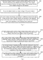
- Fig. 3 is a schematic flow chart showing a method for handling an impedance anomaly in a charging loop according to an embodiment of the present disclosure.
- the method shown in Fig. 3 can be executed by the power adapter shown in Fig. 1 , which is not described herein to avoid needless duplication.
- the method in Fig. 3 includes the following steps.
- the power adapter receives voltage indicative information from the terminal when the power adapter charges the battery.
- the voltage indicative information indicates an input voltage of the terminal from the power adapter detected by the terminal.
- step 320 the power adapter detects an output voltage of the power adapter.
- step 330 the power adapter determines, according to a difference between the input voltage and the output voltage, whether an impedance of the charging loop is abnormal, and controls the charging loop to enter into a protection state if the impedance of the charging loop is abnormal.
- the power adapter acquires the input voltage of the terminal from the power adapter detected by the terminal via a communication with the terminal, the power adapter determines based on the difference between the output voltage of the power adapter detected by itself and the input voltage of the terminal from the power adapter detected by the terminal whether the impedance of the charging loop is abnormal and controls the charging loop to enter into the protection state if the impedance of the charging loop is abnormal, such that the safety during the charging is improved.
- determining, by the power adapter according to the difference between the input voltage and the output voltage, whether the impedance of the charging loop is abnormal, and controlling, by the power adapter, the charging loop to enter into the protection state if the impedance of the charging loop is abnormal can include: determining, by the power adapter according to the difference between the input voltage and the output voltage, a level of the impedance of the charging loop; and controlling, by the power adapter according to the level of the impedance, the charging loop to enter into a protection state corresponding to the level.
- the power adapter charges the terminal via a charging interface
- detection positions of the input voltage of the terminal from the power adapter and the output voltage of the power adapter are located at two ends of the charging interface
- the impedance of the charging loop refers to an impedance of a circuit in the charging interface.
- the detection position of the input voltage of the terminal from the power adapter is located at two ends of the battery, and the impedance of the charging loop refers to an impedance of a circuit from the power adapter to the battery of the terminal.
- the method shown in Fig. 3 further includes: generating, by the power adapter, an alarm signal indicating that the impedance of the charging loop is abnormal.
- the method shown in Fig. 3 further includes: sending, by the power adapter, charging protection indicative information to the terminal if the impedance of the charging loop is abnormal, so as to indicate the terminal to control the charging loop to enter into the protection state.
- the power adapter charges the terminal via a charging interface.
- the charging interface includes a power wire and a data wire.
- the power adapter charges the terminal via the power wire in the charging interface.
- Receiving, by the power adapter, the voltage indicative information from the terminal can include: receiving, by the power adapter, the voltage indicative information from the terminal via the data wire in the charging interface.
- Fig. 4 is a schematic flow chart showing a method for handling an impedance anomaly in a charging loop according to an embodiment of the present disclosure.
- the method shown in Fig. 4 can be executed by the terminal shown in Fig. 2 , which is not described herein to avoid needless duplication.
- the method in Fig. 4 includes the following steps.
- step 410 the terminal detects an input voltage of the terminal from the power adapter when the power adapter charges the terminal.
- step 420 the terminal sends voltage indicative information to the power adapter, in which the voltage indicative information indicates the input voltage of the terminal from the power adapter detected by the terminal.
- step 430 the terminal receives charging protection indicative information from the power adapter, if the power adapter determines according to a difference between an output voltage of the power adapter and the input voltage of the terminal from the power adapter detected by the terminal that an impedance of the charging loop is abnormal.
- step 440 the terminal controls the charging loop to enter into a protection state according to an indication of the charging protection indicative information.
- the terminal communicates with the power adapter during the charging and sends the input voltage of the terminal from the power adapter detected by it, such that the power adapter determines according to the difference between the input voltage and the output voltage whether the impedance of the charging loop is abnormal. If the impedance of the charging loop is abnormal, the terminal receives the charging protection indicative information from the power adapter, and then controls the charging loop to enter into the protection state, thus improving the safety during the charging.
- a charging interface can include a power wire and a data wire.
- the power adapter charges the terminal via the power wire in the charging interface.
- Sending, by the terminal, the voltage indicative information to the power adapter can include: sending, by the terminal, the voltage indicative information to the power adapter via the data wire in the charging interface.
- detection positions of the input voltage of the terminal from the power adapter and the output voltage of the power adapter are located at two ends of the charging interface, and the impedance of the charging loop refers to an impedance of a circuit in the charging interface.
- the detection position of the input voltage of the terminal from the power adapter is located at two ends of the battery, and the impedance of the charging loop refers to an impedance of a circuit from the power adapter to the battery of the terminal.
- the method shown in Fig. 4 further includes: generating, by the terminal, an alarm signal, if the impedance of the charging loop is abnormal.
- the disclosed system, device and method can be realized by other manners.
- the above-described embodiments are only exemplary; for example, the division of said unit is only a logic function division; there can be additional dividing manners during the actual implementation.
- multiple units or components can be combined or integrated into another system, or some features can be ignored, or not implemented.
- the displayed or discussed mutual coupling or direct coupling or communication connection can be indirect coupling or communication connection of devices or units via some interfaces, in electronic, mechanical, or other forms.
- Said unit described as a separation part can be or can not be separated physically; the part displayed as a unit can be or can not be a physical unit, namely it can be located in one place, or can be distributed to multiple network units. Part or all of the units can be selected according to actual needs to achieve the purpose of the embodiment.
- all functional units in the embodiments of the disclosure can be integrated in one processing unit, or each unit exists individually in physical form, or two or more units are integrated in one unit.
- the technical solution of the disclosure substantially or its portion that contributes to the prior art or a portion of the technical solution can embody in the form of a computer software product which is stored in a memory media, including a plurality of instructions such that a computer (can be a personal computer, a server, or a network device, etc.) executes all or some steps of the methods described in each of all the embodiments.
- a computer can be a personal computer, a server, or a network device, etc.
- the previously mentioned memory media include such media capable of storing program codes as USB flash disk, portable hard drive, read-only memory (ROM), random access memory (RAM), floppy disk or compact disk.
Landscapes
- Engineering & Computer Science (AREA)
- Power Engineering (AREA)
- Physics & Mathematics (AREA)
- General Physics & Mathematics (AREA)
- Signal Processing (AREA)
- Charge And Discharge Circuits For Batteries Or The Like (AREA)
- Secondary Cells (AREA)
- Power Sources (AREA)
- Protection Of Static Devices (AREA)
- Business, Economics & Management (AREA)
- Emergency Management (AREA)
- Remote Monitoring And Control Of Power-Distribution Networks (AREA)
Abstract
Description
- Embodiments of the present disclosure relate to the charging technical field, and more particularly, to a power adapter, a terminal and a method for handling an impedance anomaly in a charging loop.
- Currently, batteries in most of electronic devices are connected with external power adapters via charging interfaces of the electronic devices to realize charging.
- During the charging, an impedance of the charging loop is usually abnormal. There are various reasons resulting in the impedance anomaly, such as, a loose contact due to a bad-inserted charging interface, a loose contact between a battery and a connector located at two ends of the battery due to dirt at the two ends of the battery.
- In a case that the impedance of the charging loop is abnormal, if the charging is still performed, charging components (such as a battery, a power adapter, and a terminal) will be damaged, thus bringing a hidden danger. In the related art, the impedance anomaly in the charging loop cannot be detected and handled, such that the safety during the charging is poor.
- Embodiments of the present disclosure provide a power adapter, a terminal and a method for handling an impedance anomaly in a charging loop, so as to improve the safety during the charging.
- In a first aspect, a power adapter is provided, including a power conversion unit and a charging interface. The power conversion unit is configured to form a charging loop with a terminal via the charging interface so as to charge a battery of the terminal. The power adapter further includes: a communication unit, configured to receive voltage indicative information from the terminal when the power adapter charges the terminal, in which the voltage indicative information indicates an input voltage of the terminal from the power adapter detected by the terminal; a detection unit, configured to detect an output voltage of the power adapter; and an anomaly handling unit, configured to determine, according to a difference between the input voltage and the output voltage, whether an impedance of the charging loop is abnormal, and to control the charging loop to enter into a protection state if the impedance of the charging loop is abnormal.
- Combined with the first aspect, in an implementation of the first aspect, the anomaly handling unit is configured to determine, according to the difference between the input voltage and the output voltage, whether the impedance of the charging loop is abnormal, and to control the charging loop to enter into the protection state if the impedance of the charging loop is abnormal, and specifically to: determine a level of the impedance according to the difference; and control, according to the level of the impedance, the charging loop to enter into a protection state corresponding to the level.
- Combined with any one of the first aspect and the above implementation, in another implementation of the first aspect, detection positions of the input voltage of the terminal from the power adapter and the output voltage of the power adapter are located at two ends of the charging interface respectively, and the impedance of the charging loop refers to an impedance of a circuit in the charging interface.
- Combined with any one of the first aspect and the above implementations, in another implementation of the first aspect, a detection position of the input voltage of the terminal from the power adapter is located at two ends of the battery of the terminal, and the impedance of the charging loop refers to an impedance of a circuit from the power adapter to the battery of the terminal.
- Combined with any one of the first aspect and the above implementations, in another implementation of the first aspect, the power adapter further includes: an alarm device, configured to generate an alarm signal if the impedance of the charging loop is abnormal.
- Combined with any one of the first aspect and the above implementations, in another implementation of the first aspect, the communication unit is configured to send charging protection indicative information to the terminal if the impedance of the charging loop is abnormal, so as to indicate the terminal to control the charging loop to enter into the protection state.
- Combined with any one of the first aspect and the above implementations, in another implementation of the first aspect, the charging interface includes a power wire and a data wire; the power conversion unit is configured to form the charging loop with the terminal via the charging interface so as to charge the battery of the terminal, and specifically to form the charging loop with the terminal via the power wire in the charging interface, so as to charge the battery of the terminal; and the communication unit is configured to receive the voltage indicative information from the terminal, and specifically to receive the voltage indicative information from the terminal via the data wire in the charging interface.
- In a second aspect, a terminal is provided, including a battery and a charging interface. The terminal is configured to form a charging loop with a power adapter via the charging interface so as to charge the battery. The terminal further includes a detection unit, a communication unit and an anomaly handling unit. The detection unit is configured to detect an input voltage of the terminal from the power adapter when the power adapter charges the terminal; the communication unit is configured to send voltage indicative information to the power adapter, in which the voltage indicative information indicates the input voltage of the terminal from the power adapter detected by the detection unit, and to receive charging protection indicative information from the power adapter if the power adapter determines based on a difference between an output voltage of the power adapter and the input voltage of the terminal from the power adapter that an impedance of the charging loop is abnormal; and the anomaly handling unit is configured to control the charging loop to enter into a protection state according to an indication of the charging protection indicative information.
- Combined with the second aspect, in an implementation of the second aspect, the charging interface includes a power wire and a data wire; the terminal is configured to form the charging loop with the power adapter via the charging interface so as to charge the battery, and specifically to form the charging loop with the power adapter via the power wire in the charging interface, so as to charge the battery; and the communication unit is configured to send the voltage indicative information to the power adapter, and specifically to send the voltage indicative information to the power adapter via the data wire in the charging interface.
- Combined with any one of the second aspect and the above implementation, in another implementation of the second aspect, detection positions of the input voltage of the terminal from the power adapter and the output voltage of the power adapter are located at two ends of the charging interface respectively, and the impedance of the charging loop refers to an impedance of a circuit in the charging interface.
- Combined with any one of the second aspect and the above implementations, in another implementation of the second aspect, the detection unit is configured to detect the input voltage of the terminal from the power adapter at two ends of the battery, and the impedance of the charging loop refers to an impedance of a circuit from the power adapter to the battery of the terminal.
- Combined with any one of the second aspect and the above implementations, in another implementation of the second aspect, the terminal further includes: an alarm device, configured to generate an alarm signal if the impedance of the charging loop is abnormal.
- In a third aspect, a method for handling an impedance anomaly in a charging loop is provided, including: receiving, by a power adapter, voltage indicative information from a terminal when the power adapter charges the battery, in which the voltage indicative information indicates an input voltage of the terminal from the power adapter detected by the terminal; detecting, by the power adapter, an output voltage of the power adapter; and determining, by the power adapter according to a difference between the input voltage and the output voltage, whether an impedance of the charging loop is abnormal; and controlling, by the power adapter, the charging loop to enter into a protection state if the impedance of the charging loop is abnormal.
- Combined with the third aspect, in an implementation of the third aspect, the method further includes: determining, by the power adapter according to the difference between the input voltage and the output voltage, whether the impedance of the charging loop is abnormal; and controlling, by the power adapter, the charging loop to enter into the protection state if the impedance of the charging loop is abnormal, includes: determining, by the power adapter, a level of the impedance according to the difference; and controlling, by the power adapter according to the level of the impedance, the charging loop to enter into a protection state corresponding to the level.
- Combined with any one of the third aspect and the above implementation, in another implementation of the third aspect, the power adapter charges the terminal via a charging interface, detection positions of the input voltage of the terminal from the power adapter and the output voltage of the power adapter are located at two ends of the charging interface respectively, and the impedance of the charging loop refers to an impedance of a circuit in the charging interface.
- Combined with any one of the third aspect and the above implementations, in another implementation of the third aspect, a detection position of the input voltage of the terminal from the power adapter is located at two ends of the battery of the terminal, and the impedance of the charging loop refers to an impedance of a circuit from the power adapter to the battery of the terminal.
- Combined with any one of the third aspect and the above implementations, in another implementation of the third aspect, the method further includes: generating, by the power adapter, an alarm signal indicating that the impedance of the charging loop is abnormal.
- Combined with any one of the third aspect and the above implementations, in another implementation of the third aspect, the method further includes: sending, by the power adapter, charging protection indicative information to the terminal if the impedance of the charging loop is abnormal, so as to indicate the terminal to control the charging loop to enter into the protection state.
- Combined with any one of the third aspect and the above implementations, in another implementation of the third aspect, the power adapter charges the terminal via a charging interface, in which the charging interface includes a power wire and a data wire, the power adapter charges the terminal via the power wire in the charging interface, and receiving, by the power adapter, the voltage indicative information from the terminal includes: receiving by the power adapter the voltage indicative information from the terminal via the data wire in the charging interface.
- In a fourth aspect, a method for handling an impedance anomaly in a charging loop is provided, including: detecting, by a terminal, an input voltage of the terminal from a power adapter when the power adapter charges the terminal; sending, by the terminal, voltage indicative information to the power adapter, in which the voltage indicative information indicates the input voltage of the terminal from the power adapter detected by the terminal; receiving, by the terminal, charging protection indicative information from the power adapter if the power adapter determines based on a difference between an output voltage of the power adapter and the input voltage of the terminal from the power adapter received from the terminal that an impedance of the charging loop is abnormal; and controlling, by the terminal, the charging loop to enter into a protection state according to an indication of the charging protection indicative information.
- Combined with the fourth aspect, in an implementation of the fourth aspect, a charging interface includes a power wire and a data wire, the power adapter charges the terminal via the power wire in the charging interface; and sending, by the terminal, the voltage indicative information to the power adapter, includes: sending, by the terminal, the voltage indicative information to the power adapter via the data wire in the charging interface.
- Combined with any one of the fourth aspect and the above implementation, in another implementation of the fourth aspect, detection positions of the input voltage of the terminal from the power adapter and the output voltage of the power adapter are located at two ends of the charging interface respectively, and the impedance of the charging loop refers to an impedance of a circuit in the charging interface.
- Combined with any one of the fourth aspect and the above implementations, in another implementation of the fourth aspect, a detection position of the input voltage of the terminal from the power adapter is located at two ends of a battery of the terminal, and the impedance of the charging loop refers to an impedance of a circuit from the power adapter to the battery of the terminal.
- Combined with any one of the fourth aspect and the above implementations, in another implementation of the fourth aspect, the method further includes: generating, by the terminal, an alarm signal if the impedance of the charging loop is abnormal.
- In embodiments of the present disclosure, the power adapter acquires the input voltage of the terminal from the power adapter detected by the terminal via a communication with the terminal, the power adapter determines based on the difference between the output voltage of the power adapter detected by itself and the input voltage of the terminal from the power adapter detected by the terminal whether the impedance of the charging loop is abnormal and controls the charging loop to enter into the protection state if the impedance of the charging loop is abnormal, such that the safety during the charging is improved.
- In order to make the technical solutions of embodiments of the present disclosure more clearly, the accompanying drawings used in the description of embodiments of the present disclosure are briefly described hereunder. Obviously, the described drawings are merely some embodiments of present disclosure. For those skilled in the art, other drawings can be obtained based on these drawings without any creative work.
-
Fig. 1 is a schematic block diagram showing a power adapter according to an embodiment of the present disclosure; -
Fig. 2 is a schematic block diagram showing a terminal according to an embodiment of the present disclosure; -
Fig. 3 is a schematic flow chart showing a method for handling an impedance anomaly in a charging loop according to an embodiment of the present disclosure; and -
Fig. 4 is a schematic flow chart showing a method for handling an impedance anomaly in a charging loop according to an embodiment of the present disclosure. - The technical solutions in embodiments of the present disclosure are hereinafter described clearly and completely with reference to the accompanying drawings in embodiments of the present disclosure as follows. Apparently, the described embodiments are merely a part of embodiments of the present disclosure, rather than all embodiments of the present disclosure. All other embodiments obtained by those skilled in the art based on embodiments of the present disclosure without creative efforts shall fall within the protection scope of the present disclosure.
-
Fig. 1 is a schematic block diagram showing a power adapter according to an embodiment of the present disclosure. Thepower adapter 10 shown inFig. 1 includes: a power conversion unit 11 and acharging interface 12. The power conversion unit 11 is configured to form a charging loop with a terminal via thecharging interface 12, so as to charge a battery of the terminal. Thepower adapter 10 further includes a communication unit 13, a detection unit 14and ananomaly handling unit 15. - The communication unit 13 is configured to receive voltage indicative information from the terminal when the power adapter charges the terminal, in which the voltage indicative information indicates an input voltage of the terminal from the power adapter detected by the terminal.
- The
detection unit 14 is configured to detect an output voltage of the power adapter. - The
anomaly handling unit 15 is configured to determine, according to a difference between the input voltage and the output voltage, whether an impedance of the charging loop is abnormal, and to control the charging loop to enter into a protection state if the impedance of the charging loop is abnormal. - In embodiments of the present disclosure, the power adapter acquires the input voltage of the terminal from the power adapter detected by the terminal via a communication with the terminal, the power adapter determines based on the difference between the output voltage of the power adapter detected by itself and the input voltage of the terminal from the power adapter detected by the terminal whether the impedance of the charging loop is abnormal and controls the charging loop to enter into the protection state if the impedance of the charging loop is abnormal, such that the safety during the charging is improved.
- It should be understood that, the above
anomaly handling unit 15 controlling the charging loop to enter into the protection state can include: reducing by theanomaly handling unit 15 the output voltage of thepower adapter 10; reducing by theanomaly handling unit 15 output current of thepower adapter 10; or disconnecting by theanomaly handling unit 15 the charging loop. - Alternatively, as an embodiment, the above
anomaly handling unit 15 is configured to determine, according to the difference between the input voltage and the output voltage, whether the impedance of the charging loop is abnormal, and to control the charging loop to enter into the protection state if the impedance of the charging loop is abnormal, and specifically to: determine a level of the impedance according to the difference; and control, according to the level of the impedance, the charging loop to enter into a protection state corresponding to the level. - For example, a correspondence between the level of impedance and the difference between the input voltage of the terminal from the power adapter and the output voltage of the power adapter can be preset. After determining an actual difference between the input voltage of the terminal from the power adapter and the output voltage of the power adapter, the
anomaly handling unit 15 can find the level of impedance corresponding to the actual difference based on the above correspondence. Each level of impedance corresponds to a distinct protection state. For example, the level of impedance can be divided into "light", "middle" and "heavy". If the level of impedance is "light", it can control the charging loop to continue to charge with large current. If the level of impedance is "middle", it can control the charging loop to charge with small current. If the level of impedance is "heavy", it can control the charging loop to be turned off. - It should be noted that, a position where the output voltage is detected by the power adapter and a position where the input voltage of the terminal from the power adapter is detected by the terminal are not limited herein, and can be determined according to different demands.
- For example, the detection positions of the input voltage of the terminal from the power adapter and the output voltage of the power adapter can be located at two ends of the charging interface respectively, and the impedance of the charging loop refers to an impedance of a circuit in the charging interface. It should be understood that, the above detection positions of the input voltage of the terminal from the power adapter and the output voltage of the power adapter being located at two ends of the charging interface respectively means that, the terminal detects the input voltage of the terminal from the power adapter at one side of the charging interface, and the power adapter detects the output voltage of the power adapter at the other side of the charging interface. The above detection positions of the input voltage of the terminal from the power adapter and the output voltage of the power adapter being located at two ends of the charging interface respectively means that, the position where the power adapter detects the output voltage and the position where the terminal detects the input voltage of the terminal from the power adapter are close to the charging interface connected thereto, if the voltage drop of any one of the voltages detected by the terminal and the power adapter is abnormal, it can be determined that this happens due to the impedance anomaly of the circuit in the charging interface.
- For another example, the detection position of the input voltage of the terminal from the power adapter is located at two ends of the battery, and the impedance of the charging loop refers to an impedance of a circuit from the power adapter to the battery of the terminal. Since the input current of the power adapter finally reaches the two ends of the battery after flowing through various components in the terminal, when the terminal detects the input voltage of the terminal from the power adapter at the two ends of the battery, the difference between the of the terminal from the power adapter and the output voltage of the power adapter can indicate the impedance of the whole charging loop.
- Alternatively, as an embodiment, the
power adapter 10 further includes: an alarm device, configured to generate an alarm signal if the impedance of the charging loop is abnormal. The alarm device can be a sound alarm device or a lamp. Taking the impedance of the charging loop being the impedance of the circuit in the charging interface as an example, when the alarm device raises an alarm, it means that the charging interface has a loose contact, such that a user is reminded to re-connect the charging interface between the power adapter and the terminal. - Alternatively, as an embodiment, if the impedance of the charging loop is abnormal, the communication unit 13 is configured to send charging protection indicative information to the terminal, so as to indicate the terminal to control the charging loop to enter into the protection state.
- In embodiments of the present disclosure, if the impedance of the charging loop is abnormal, the power adapter not only controls the charging loop to enter into the protection state, but also notices the terminal to control the charging loop to enter into the protection state. In this way, even if the anomaly handing unit in the power adapter loses efficacy and the power adapter cannot control the charging loop to enter into the protection state, the terminal can control the charging loop to enter into the protection state, thus further improving the safety during the charging.
- Alternatively, as an embodiment, the charging
interface 12 includes a power wire and a data wire. The power conversion unit 11 is configured to form the charging loop with the terminal via the charginginterface 12 so as to charge the battery of the terminal, and specifically to form the charging loop with the terminal via the power wire in the charginginterface 12 so as to charge the battery of the terminal. The communication unit 13 is configured to receive the voltage indicative information from the terminal when thepower adapter 10 charges the terminal, and specifically to: receive the voltage indicative information from the terminal via the data wire in the charginginterface 12. - For example, the charging interface is a USB (Universal Serial Bus) interface or a micro USB interface. The above power wire is a power wire in the USB interface, such as +5V power wire and -5V power wire. The above data wire is a data wire in the USB interface, such as D+ wire and D- wire.
-
Fig. 2 is a schematic block diagram showing a terminal according to an embodiment of the present disclosure. The terminal 20 shown inFig. 2 includes abattery 21 and a charging interface 22. The terminal 20 is configured to form a charging loop with a power adapter via the charging interface 22, so as to charge thebattery 21. The terminal 20 further includes: adetection unit 23, a communication unit 24 and ananomaly handling unit 25. - The
detection unit 23 is configured to detect an input voltage of the terminal from the power adapter when the power adapter charges the terminal 20. - The communication unit 24 is configured to send voltage indicative information to the power adapter, in which the voltage indicative information indicates the input voltage of the terminal from the power adapter detected by the
detection unit 23. - The communication unit 24 is configured to receive charging protection indicative information from the power adapter if the power adapter determines based on a difference between an output voltage of the power adapter and the input voltage of the terminal from the power adapter that an impedance of the charging loop is abnormal.
- The
anomaly handing unit 25 is configured to control the charging loop to enter into a protection state according to an indication of the charging protection indicative information. - In embodiments of the present disclosure, the terminal communicates with the power adapter during the charging and sends the input voltage of the terminal from the power adapter detected by it, such that the power adapter determines according to the difference between the input voltage and the output voltage whether the impedance of the charging loop is abnormal. If the impedance of the charging loop is abnormal, the terminal receives the charging protection indicative information from the power adapter, and then controls the charging loop to enter into the protection state, thus improving the safety during the charging.
- Alternatively, as an embodiment, the charging interface 22 can include a power wire and a data wire. The terminal 20 is configured to form the charging loop with the power adapter via the charging interface 22 so as to charge the
battery 21, and specifically to: form the charging loop with the power adapter via the power wire in the charging interface 22 so as to charge thebattery 21. The communication unit 24 is configured to send the voltage indicative information to the power adapter, and specifically to: send the voltage indicative information to the power adapter via the date wire in the charging interface 22. - For example, the charging interface is a USB (Universal Serial Bus) interface or a micro USB interface. The above power wire is a power wire in the USB interface, such as +5V power wire and -5V power wire. The above data wire is a data wire in the USB interface, such as D+ wire and D- wire.
- It should be noted that, a position where the output voltage is detected by the power adapter and a position where the input voltage of the terminal from the power adapter is detected by the terminal are not limited herein, and can be determined according to different demands.
- For example, the detection positions of the input voltage of the terminal from the power adapter and the output voltage of the power adapter can be located at two ends of the charging interface respectively, and the impedance of the charging loop refers to an impedance of a circuit in the charging interface. The above detection positions of the input voltage of the terminal from the power adapter and the output voltage of the power adapter being located at two ends of the charging interface respectively means that, the position where the power adapter detects the output voltage and the position where the terminal detects the input voltage of the terminal from the power adapter are close to the charging interface connected thereto, if the voltage drop of any one of the voltages detected by the terminal and the power adapter is abnormal, it can be determined that this happens due to the impedance anomaly of the circuit in the charging interface.
- For another example, the detection position of the input voltage of the terminal from the power adapter is located at two ends of the battery, and the impedance of the charging loop refers to an impedance of a circuit from the power adapter to the battery of the terminal. Since the input current of the power adapter finally reaches the two ends of the battery after flowing through various components in the terminal, when the terminal detects the input voltage of the terminal from the power adapter at the two ends of the battery, the difference between the of the terminal from the power adapter and the output voltage of the power adapter can indicate the impedance of the whole charging loop.
- Alternatively, as an embodiment, the terminal 20 further includes: an alarm device, configured to generate an alarm signal if the impedance of the charging loop is abnormal. The alarm device can be a sound alarm device or a lamp. Taking the impedance of the charging loop being the impedance of the circuit in the charging interface as an example, when the alarm device raises an alarm, it means that the charging interface has a loose contact, such that a user is reminded to re-connect the charging interface between the power adapter and the terminal.
-
Fig. 3 is a schematic flow chart showing a method for handling an impedance anomaly in a charging loop according to an embodiment of the present disclosure. The method shown inFig. 3 can be executed by the power adapter shown inFig. 1 , which is not described herein to avoid needless duplication. The method inFig. 3 includes the following steps. - In
step 310, the power adapter receives voltage indicative information from the terminal when the power adapter charges the battery. The voltage indicative information indicates an input voltage of the terminal from the power adapter detected by the terminal. - In
step 320, the power adapter detects an output voltage of the power adapter. - In
step 330, the power adapter determines, according to a difference between the input voltage and the output voltage, whether an impedance of the charging loop is abnormal, and controls the charging loop to enter into a protection state if the impedance of the charging loop is abnormal. - In embodiments of the present disclosure, the power adapter acquires the input voltage of the terminal from the power adapter detected by the terminal via a communication with the terminal, the power adapter determines based on the difference between the output voltage of the power adapter detected by itself and the input voltage of the terminal from the power adapter detected by the terminal whether the impedance of the charging loop is abnormal and controls the charging loop to enter into the protection state if the impedance of the charging loop is abnormal, such that the safety during the charging is improved.
- Alternatively, as an embodiment, determining, by the power adapter according to the difference between the input voltage and the output voltage, whether the impedance of the charging loop is abnormal, and controlling, by the power adapter, the charging loop to enter into the protection state if the impedance of the charging loop is abnormal can include: determining, by the power adapter according to the difference between the input voltage and the output voltage, a level of the impedance of the charging loop; and controlling, by the power adapter according to the level of the impedance, the charging loop to enter into a protection state corresponding to the level.
- Alternatively, as an embodiment, the power adapter charges the terminal via a charging interface, and detection positions of the input voltage of the terminal from the power adapter and the output voltage of the power adapter are located at two ends of the charging interface, and the impedance of the charging loop refers to an impedance of a circuit in the charging interface.
- Alternatively, as an embodiment, the detection position of the input voltage of the terminal from the power adapter is located at two ends of the battery, and the impedance of the charging loop refers to an impedance of a circuit from the power adapter to the battery of the terminal.
- Alternatively, as an embodiment, the method shown in
Fig. 3 further includes: generating, by the power adapter, an alarm signal indicating that the impedance of the charging loop is abnormal. - Alternatively, as an embodiment, the method shown in
Fig. 3 further includes: sending, by the power adapter, charging protection indicative information to the terminal if the impedance of the charging loop is abnormal, so as to indicate the terminal to control the charging loop to enter into the protection state. - Alternatively, as an embodiment, the power adapter charges the terminal via a charging interface. The charging interface includes a power wire and a data wire. The power adapter charges the terminal via the power wire in the charging interface. Receiving, by the power adapter, the voltage indicative information from the terminal can include: receiving, by the power adapter, the voltage indicative information from the terminal via the data wire in the charging interface.
-
Fig. 4 is a schematic flow chart showing a method for handling an impedance anomaly in a charging loop according to an embodiment of the present disclosure. The method shown inFig. 4 can be executed by the terminal shown inFig. 2 , which is not described herein to avoid needless duplication. The method inFig. 4 includes the following steps. - In
step 410, the terminal detects an input voltage of the terminal from the power adapter when the power adapter charges the terminal. - In
step 420, the terminal sends voltage indicative information to the power adapter, in which the voltage indicative information indicates the input voltage of the terminal from the power adapter detected by the terminal. - In
step 430, the terminal receives charging protection indicative information from the power adapter, if the power adapter determines according to a difference between an output voltage of the power adapter and the input voltage of the terminal from the power adapter detected by the terminal that an impedance of the charging loop is abnormal. - In
step 440, the terminal controls the charging loop to enter into a protection state according to an indication of the charging protection indicative information. - In embodiments of the present disclosure, the terminal communicates with the power adapter during the charging and sends the input voltage of the terminal from the power adapter detected by it, such that the power adapter determines according to the difference between the input voltage and the output voltage whether the impedance of the charging loop is abnormal. If the impedance of the charging loop is abnormal, the terminal receives the charging protection indicative information from the power adapter, and then controls the charging loop to enter into the protection state, thus improving the safety during the charging.
- Alternatively, as an embodiment, a charging interface can include a power wire and a data wire. The power adapter charges the terminal via the power wire in the charging interface. Sending, by the terminal, the voltage indicative information to the power adapter can include: sending, by the terminal, the voltage indicative information to the power adapter via the data wire in the charging interface.
- Alternatively, as an embodiment, detection positions of the input voltage of the terminal from the power adapter and the output voltage of the power adapter are located at two ends of the charging interface, and the impedance of the charging loop refers to an impedance of a circuit in the charging interface.
- Alternatively, as an embodiment, the detection position of the input voltage of the terminal from the power adapter is located at two ends of the battery, and the impedance of the charging loop refers to an impedance of a circuit from the power adapter to the battery of the terminal.
- Alternatively, as an embodiment, the method shown in
Fig. 4 further includes: generating, by the terminal, an alarm signal, if the impedance of the charging loop is abnormal. - Those skilled in the art can be aware that, in combination with the examples described in the embodiments disclosed in this specification, units and algorithm steps can be implemented by electronic hardware, or a combination of computer software and electronic hardware. Whether the functions are executed by hardware or software depends on particular applications and design constraint conditions of the technical solutions. Those skilled in the art can use different methods to implement the described functions for each particular application, but it should not be considered that the implementation goes beyond the scope of the present disclosure.
- It would be appreciated by those skilled in the art that, for the purpose of simplification convenience of description, concerning the specific working process of the above system, device and unit as described above, reference is made to the method embodiments of the present disclosure, which will not be elaborated herein.
- In several embodiments provided in the application, it should be understood that the disclosed system, device and method can be realized by other manners. For example, the above-described embodiments are only exemplary; for example, the division of said unit is only a logic function division; there can be additional dividing manners during the actual implementation. For example, multiple units or components can be combined or integrated into another system, or some features can be ignored, or not implemented. Another point, the displayed or discussed mutual coupling or direct coupling or communication connection can be indirect coupling or communication connection of devices or units via some interfaces, in electronic, mechanical, or other forms.
- Said unit described as a separation part can be or can not be separated physically; the part displayed as a unit can be or can not be a physical unit, namely it can be located in one place, or can be distributed to multiple network units. Part or all of the units can be selected according to actual needs to achieve the purpose of the embodiment.
- In addition, all functional units in the embodiments of the disclosure can be integrated in one processing unit, or each unit exists individually in physical form, or two or more units are integrated in one unit.
- If said function is realized in the form of software function unit and sold or used as an independent product, it can be stored in a computer readable storage medium. With such an understanding, the technical solution of the disclosure substantially or its portion that contributes to the prior art or a portion of the technical solution can embody in the form of a computer software product which is stored in a memory media, including a plurality of instructions such that a computer (can be a personal computer, a server, or a network device, etc.) executes all or some steps of the methods described in each of all the embodiments. And the previously mentioned memory media include such media capable of storing program codes as USB flash disk, portable hard drive, read-only memory (ROM), random access memory (RAM), floppy disk or compact disk.
- The above descriptions are only specific embodiments of the disclosure, but not intended to limit the protection scope of the disclosure. The variation or replacement easily thought of by those skilled in the art within the technical scope disclosed by the disclosure, shall fall within the protection scope of the disclosure. Therefore, the protection scope of the disclosure shall be determined with reference to the protection scope of the claims.
Claims (24)
- A power adapter, comprising a power conversion unit and a charging interface, the power conversion unit being configured to form a charging loop with a terminal via the charging interface so as to charge a battery of the terminal, and being characterized at that, the power adapter further comprises:a communication unit, configured to receive voltage indicative information from the terminal when the power adapter charges the terminal, wherein the voltage indicative information indicates an input voltage of the terminal from the power adapter detected by the terminal;a detection unit, configured to detect an output voltage of the power adapter; andan anomaly handling unit, configured to determine, according to a difference between the input voltage and the output voltage, whether an impedance of the charging loop is abnormal, and to control the charging loop to enter into a protection state if the impedance of the charging loop is abnormal.
- The power adapter according to claim 1, being characterized at, the anomaly handling unit is configured to determine, according to the difference between the input voltage and the output voltage, whether the impedance of the charging loop is abnormal, and to control the charging loop to enter into the protection state if the impedance of the charging loop is abnormal, and specifically to:determine a level of the impedance according to the difference; andcontrol, according to the level of the impedance, the charging loop to enter into a protection state corresponding to the level.
- The power adapter according to claim 1 or 2, being characterized at that, detection positions of the input voltage of the terminal from the power adapter and the output voltage of the power adapter are located at two ends of the charging interface respectively, and the impedance of the charging loop refers to an impedance of a circuit in the charging interface.
- The power adapter according to claim 1 or 2, being characterized at that, a detection position of the input voltage of the terminal from the power adapter is located at two ends of the battery of the terminal, and the impedance of the charging loop refers to an impedance of a circuit from the power adapter to the battery of the terminal.
- The power adapter according to any one of claims 1-4, being characterized at, further comprising:an alarm device, configured to generate an alarm signal if the impedance of the charging loop is abnormal.
- The power adapter according to any one of claims 1-5, being characterized at that, the communication unit is configured to send charging protection indicative information to the terminal if the impedance of the charging loop is abnormal, so as to indicate the terminal to control the charging loop to enter into the protection state.
- The power adapter according to any one of claims 1-6, being characterized at that, the charging interface comprises a power wire and a data wire;
the power conversion unit is configured to form the charging loop with the terminal via the charging interface so as to charge the battery of the terminal, and specifically to:form the charging loop with the terminal via the power wire in the charging interface, so as to charge the battery of the terminal; andthe communication unit is configured to receive the voltage indicative information from the terminal, and specifically to:receive the voltage indicative information from the terminal via the data wire in the charging interface. - A terminal, comprising a battery and a charging interface, the terminal being configured to form a charging loop with a power adapter via the charging interface so as to charge the battery, and being characterized at that, the terminal further comprises a detection unit, a communication unit and an anomaly handling unit, wherein
the detection unit is configured to detect an input voltage of the terminal from the power adapter when the power adapter charges the terminal;
the communication unit is configured to send voltage indicative information to the power adapter, wherein the voltage indicative information indicates the input voltage of the terminal from the power adapter detected by the detection unit, and to receive charging protection indicative information from the power adapter if the power adapter determines based on a difference between an output voltage of the power adapter and the input voltage of the terminal from the power adapter that an impedance of the charging loop is abnormal; and
the anomaly handling unit is configured to control the charging loop to enter into a protection state according to an indication of the charging protection indicative information. - The terminal according to claim 8, being characterized at that, the charging interface comprises a power wire and a data wire;
the terminal is configured to form the charging loop with the power adapter via the charging interface so as to charge the battery, and specifically to:form the charging loop with the power adapter via the power wire in the charging interface, so as to charge the battery; andthe communication unit is configured to send the voltage indicative information to the power adapter, and specifically to:send the voltage indicative information to the power adapter via the data wire in the charging interface. - The terminal according to claim 8 or 9, being characterized at that, detection positions of the input voltage of the terminal from the power adapter and the output voltage of the power adapter are located at two ends of the charging interface respectively, and the impedance of the charging loop refers to an impedance of a circuit in the charging interface.
- The terminal according to claim 8 or 9, being characterized at that, the detection unit is configured to detect the input voltage of the terminal from the power adapter at two ends of the battery, and the impedance of the charging loop refers to an impedance of a circuit from the power adapter to the battery of the terminal.
- The terminal according to any one of claims 8-11, being characterized at, further comprising:an alarm device, configured to generate an alarm signal if the impedance of the charging loop is abnormal.
- A method for handling an impedance anomaly in a charging loop, being characterized at, comprising:receiving, by a power adapter, voltage indicative information from a terminal when the power adapter charges the battery, wherein the voltage indicative information indicates an input voltage of the terminal from the power adapter detected by the terminal;detecting, by the power adapter, an output voltage of the power adapter; anddetermining, by the power adapter according to a difference between the input voltage and the output voltage, whether an impedance of the charging loop is abnormal; and controlling, by the power adapter, the charging loop to enter into a protection state if the impedance of the charging loop is abnormal.
- The method according to claim 13, being characterized at that, determining, by the power adapter according to the difference between the input voltage and the output voltage, whether the impedance of the charging loop is abnormal; and controlling, by the power adapter, the charging loop to enter into the protection state if the impedance of the charging loop is abnormal, comprises:determining, by the power adapter, a level of the impedance according to the difference; andcontrolling, by the power adapter according to the level of the impedance, the charging loop to enter into a protection state corresponding to the level.
- The method according to claim 13 or 14, being characterized at that, the power adapter charges the terminal via a charging interface, detection positions of the input voltage of the terminal from the power adapter and the output voltage of the power adapter are located at two ends of the charging interface respectively, and the impedance of the charging loop refers to an impedance of a circuit in the charging interface.
- The method according to claim 13 or 14, being characterized at that, a detection position of the input voltage of the terminal from the power adapter is located at two ends of the battery of the terminal, and the impedance of the charging loop refers to an impedance of a circuit from the power adapter to the battery of the terminal.
- The method according to any one of claims 13-16, being characterized at, further comprising:generating, by the power adapter, an alarm signal indicating that the impedance of the charging loop is abnormal.
- The method according to any one of claims 13-17, being characterized at, further comprising:sending, by the power adapter, charging protection indicative information to the terminal if the impedance of the charging loop is abnormal, so as to indicate the terminal to control the charging loop to enter into the protection state.
- The method according to any one of claims 13-18, being characterized at that, the power adapter charges the terminal via a charging interface, wherein
the charging interface comprises a power wire and a data wire;
the power adapter charges the terminal via the power wire in the charging interface; and receiving, by the power adapter, the voltage indicative information from the terminal comprises: receiving by the power adapter the voltage indicative information from the terminal via the data wire in the charging interface. - A method for handling an impedance anomaly in a charging loop, being characterized at, comprising:detecting, by a terminal, an input voltage of the terminal from a power adapter when the power adapter charges the terminal;sending, by the terminal, voltage indicative information to the power adapter, wherein the voltage indicative information indicates the input voltage of the terminal from the power adapter detected by the terminal;receiving, by the terminal, charging protection indicative information from the power adapter if the power adapter determines based on a difference between an output voltage of the power adapter and the input voltage of the terminal from the power adapter received from the terminal that an impedance of the charging loop is abnormal; andcontrolling, by the terminal, the charging loop to enter into a protection state according to an indication of the charging protection indicative information.
- The method according to claim 20, being characterized at that, a charging interface comprises a power wire and a data wire, the power adapter charges the terminal via the power wire in the charging interface; and
sending, by the terminal, the voltage indicative information to the power adapter, comprises:sending, by the terminal, the voltage indicative information to the power adapter via the data wire in the charging interface. - The method according to claim 20 or 21, being characterized at that, detection positions of the input voltage of the terminal from the power adapter and the output voltage of the power adapter are located at two ends of the charging interface respectively, and the impedance of the charging loop refers to an impedance of a circuit in the charging interface.
- The method according to claim 20 or 21, being characterized at that, a detection position of the input voltage of the terminal from the power adapter is located at two ends of a battery of the terminal, and the impedance of the charging loop refers to an impedance of a circuit from the power adapter to the battery of the terminal.
- The method according to any one of claims 20-23, being characterized at, further comprising:generating, by the terminal, an alarm signal if the impedance of the charging loop is abnormal.
Priority Applications (2)
| Application Number | Priority Date | Filing Date | Title |
|---|---|---|---|
| PL15743208T PL3101437T3 (en) | 2014-01-28 | 2015-01-09 | Power adapter, terminal, and method for handling impedance anomaly in charging loop |
| EP18207105.0A EP3484013B1 (en) | 2014-01-28 | 2015-01-09 | Power adapter, terminal, and method for processing impedance exception of charing loop |
Applications Claiming Priority (3)
| Application Number | Priority Date | Filing Date | Title |
|---|---|---|---|
| CN201410043148.3A CN104810877B (en) | 2014-01-28 | 2014-01-28 | Battery charging device and method |
| CN201410042716.8A CN104808104A (en) | 2014-01-28 | 2014-01-28 | Interface plugging anomaly detection circuit and method |
| PCT/CN2015/070461 WO2015113463A1 (en) | 2014-01-28 | 2015-01-09 | Power adapter, terminal, and method for processing impedance exception of charging loop |
Related Child Applications (2)
| Application Number | Title | Priority Date | Filing Date |
|---|---|---|---|
| EP18207105.0A Division-Into EP3484013B1 (en) | 2014-01-28 | 2015-01-09 | Power adapter, terminal, and method for processing impedance exception of charing loop |
| EP18207105.0A Division EP3484013B1 (en) | 2014-01-28 | 2015-01-09 | Power adapter, terminal, and method for processing impedance exception of charing loop |
Publications (3)
| Publication Number | Publication Date |
|---|---|
| EP3101437A1 true EP3101437A1 (en) | 2016-12-07 |
| EP3101437A4 EP3101437A4 (en) | 2017-11-01 |
| EP3101437B1 EP3101437B1 (en) | 2019-03-06 |
Family
ID=53756226
Family Applications (4)
| Application Number | Title | Priority Date | Filing Date |
|---|---|---|---|
| EP15743208.9A Active EP3101437B1 (en) | 2014-01-28 | 2015-01-09 | Power adapter, terminal, and method for handling impedance anomaly in charging loop |
| EP18201161.9A Active EP3451487B1 (en) | 2014-01-28 | 2015-01-09 | Power adapter, terminal, and method for processing impedance anomalies in charging loop |
| EP18207105.0A Active EP3484013B1 (en) | 2014-01-28 | 2015-01-09 | Power adapter, terminal, and method for processing impedance exception of charing loop |
| EP15742934.1A Active EP3101762B1 (en) | 2014-01-28 | 2015-01-09 | Power adapter, terminal, and method for processing impedance anomalies in charging circuit |
Family Applications After (3)
| Application Number | Title | Priority Date | Filing Date |
|---|---|---|---|
| EP18201161.9A Active EP3451487B1 (en) | 2014-01-28 | 2015-01-09 | Power adapter, terminal, and method for processing impedance anomalies in charging loop |
| EP18207105.0A Active EP3484013B1 (en) | 2014-01-28 | 2015-01-09 | Power adapter, terminal, and method for processing impedance exception of charing loop |
| EP15742934.1A Active EP3101762B1 (en) | 2014-01-28 | 2015-01-09 | Power adapter, terminal, and method for processing impedance anomalies in charging circuit |
Country Status (14)
| Country | Link |
|---|---|
| US (4) | US10320206B2 (en) |
| EP (4) | EP3101437B1 (en) |
| JP (3) | JP6320544B2 (en) |
| KR (2) | KR20160136283A (en) |
| CN (3) | CN110212617A (en) |
| AU (1) | AU2015210565B2 (en) |
| DK (2) | DK3101762T3 (en) |
| ES (2) | ES2717477T3 (en) |
| HU (2) | HUE042991T2 (en) |
| MY (1) | MY173120A (en) |
| PL (2) | PL3101762T3 (en) |
| PT (2) | PT3101437T (en) |
| SG (1) | SG11201606222UA (en) |
| WO (2) | WO2015113463A1 (en) |
Cited By (2)
| Publication number | Priority date | Publication date | Assignee | Title |
|---|---|---|---|---|
| CN107453426A (en) * | 2017-07-26 | 2017-12-08 | 杨建伟 | A kind of intelligent charger of intelligent terminal |
| EP3734310A4 (en) * | 2017-12-27 | 2021-10-13 | ZTE Corporation | PERFORMANCE MONITORING PROCEDURES, SYSTEM AND POWER SUPPLY |
Families Citing this family (27)
| Publication number | Priority date | Publication date | Assignee | Title |
|---|---|---|---|---|
| KR20160136283A (en) * | 2014-01-28 | 2016-11-29 | 광동 오포 모바일 텔레커뮤니케이션즈 코포레이션 리미티드 | Power adapter, terminal, and method for processing impedance anomalies in charging circuit |
| US20170244265A1 (en) * | 2014-11-11 | 2017-08-24 | Guangdong Oppo Mobile Telecommunications Corp., Ltd. | Communication method, power adaptor and terminal |
| KR101898185B1 (en) * | 2014-11-11 | 2018-09-12 | 광동 오포 모바일 텔레커뮤니케이션즈 코포레이션 리미티드 | Power adaptor, terminal and charging system |
| ES2771901T3 (en) * | 2014-12-31 | 2020-07-07 | Huawei Tech Co Ltd | Charge protection procedure and apparatus |
| RU2678776C1 (en) * | 2015-05-19 | 2019-02-01 | Хуавэй Текнолоджиз Ко., Лтд. | Method of charging, charger and terminal |
| EP3206279B1 (en) * | 2015-12-16 | 2020-11-11 | Guangdong Oppo Mobile Telecommunications Corp., Ltd. | Charging control method and device, power adapter, and mobile terminal |
| ES2712066T3 (en) * | 2016-01-05 | 2019-05-09 | Guangdong Oppo Mobile Telecommunications Corp Ltd | Fast charging method, mobile terminal and adapter |
| US20170201101A1 (en) * | 2016-01-12 | 2017-07-13 | Richtek Technology Corporation | Mobile device charger for charging mobile device and related adaptive charging voltage generator |
| US10170923B2 (en) | 2016-01-12 | 2019-01-01 | Richtek Technology Corporation | Adaptive buck converter with monitor circuit and charging cable using the same |
| CN109565171B (en) * | 2016-08-29 | 2020-08-07 | 华为技术有限公司 | Charging protection method, terminal and charger |
| CN107991571A (en) * | 2016-10-26 | 2018-05-04 | 中兴通讯股份有限公司 | It is a kind of to detect the abnormal method, apparatus of charging and power supply adaptor |
| US20180267587A1 (en) * | 2017-03-20 | 2018-09-20 | Google Inc. | Comparing electrical quantity output by power adapter to electrical quantity input by computing device |
| CN106972736B (en) * | 2017-05-26 | 2023-06-30 | 深圳市乐得瑞科技有限公司 | Power supply adapting device, control method and device |
| KR102500690B1 (en) * | 2017-09-18 | 2023-02-17 | 삼성전자주식회사 | Battery status based charging control method and appratus thereof |
| CN107508359A (en) * | 2017-09-25 | 2017-12-22 | 上海木爷机器人技术有限公司 | The automatic charging system and method for a kind of robot |
| EP3719516B1 (en) * | 2018-09-30 | 2022-11-02 | Guangdong Oppo Mobile Telecommunications Corp., Ltd. | Charging device test system and method |
| EP3722820B1 (en) * | 2018-09-30 | 2023-08-23 | Guangdong Oppo Mobile Telecommunications Corp., Ltd. | Test board, test system and test method for charging device |
| US11368032B2 (en) | 2018-09-30 | 2022-06-21 | Guangdong Oppo Mobile Telecommunications Corp., Ltd. | Test system and test method for charging device |
| US11305665B2 (en) | 2019-03-04 | 2022-04-19 | General Electric Company | Cyber-attack detection and electrical system stability for electric vehicle charging infrastructure |
| CN112310754B (en) * | 2019-07-26 | 2022-06-03 | 致伸科技股份有限公司 | Universal Serial Bus Interface Conversion Device |
| CN110824286B (en) * | 2019-11-29 | 2022-07-19 | 恒大恒驰新能源汽车研究院(上海)有限公司 | Charging abnormality detection method, charging device, computer device, and storage medium |
| CN112269462A (en) * | 2020-10-15 | 2021-01-26 | 苏州浪潮智能科技有限公司 | Board card protection method, device and equipment |
| WO2022087961A1 (en) * | 2020-10-29 | 2022-05-05 | 深圳市大疆创新科技有限公司 | Power supply control method and apparatus, and electric device |
| US11699998B2 (en) * | 2021-08-17 | 2023-07-11 | Allison Transmission, Inc. | Switch assembly with feedback signal for fault detection |
| CN113923555B (en) * | 2021-10-13 | 2024-02-06 | 维沃移动通信有限公司 | Charging control circuit and charging control method for earphone |
| JP7735974B2 (en) * | 2022-10-12 | 2025-09-09 | トヨタ自動車株式会社 | vehicle |
| TWI874997B (en) * | 2023-05-18 | 2025-03-01 | 凱銳光電股份有限公司 | Monitoring system and monitoring method of wire between power supply end and apparatus end |
Family Cites Families (116)
| Publication number | Priority date | Publication date | Assignee | Title |
|---|---|---|---|---|
| US4207611A (en) | 1978-12-18 | 1980-06-10 | Ford Motor Company | Apparatus and method for calibrated testing of a vehicle electrical system |
| JPH05219656A (en) * | 1992-02-03 | 1993-08-27 | Nippon Densan Corp | Batter charger |
| JP3303155B2 (en) | 1995-01-19 | 2002-07-15 | 京セラ株式会社 | Battery charger |
| JPH08237947A (en) | 1995-02-27 | 1996-09-13 | Fujitsu Ltd | Power supply |
| JPH08237949A (en) | 1995-02-27 | 1996-09-13 | Nichicon Corp | Dc power supply circuit |
| JP2914259B2 (en) | 1995-12-14 | 1999-06-28 | 日本電気株式会社 | Portable electronic device and charge control method for portable electronic device |
| JP3508384B2 (en) * | 1996-04-05 | 2004-03-22 | ソニー株式会社 | Battery charging apparatus and method, and battery pack |
| US5781456A (en) | 1997-07-11 | 1998-07-14 | Space Systems/Loral, Inc. | Software select and test |
| JP2000134816A (en) * | 1998-10-27 | 2000-05-12 | Toshiba Corp | Electronic equipment and AC adapter |
| JP2001180083A (en) | 1999-12-24 | 2001-07-03 | Fuji Xerox Co Ltd | Printer |
| US6829726B1 (en) | 2000-03-06 | 2004-12-07 | Pc-Doctor, Inc. | Method and system for testing a universal serial bus within a computing device |
| TW512232B (en) | 2001-05-08 | 2002-12-01 | Prolific Technology Inc | USB connection-detection circuitry and operation methods of the same |
| KR100423902B1 (en) | 2001-06-16 | 2004-03-22 | 삼성전자주식회사 | Universal serial bus low speed transceiver capable of controlling corssover voltage |
| JP4499966B2 (en) | 2001-09-14 | 2010-07-14 | 株式会社リコー | Secondary battery charging circuit |
| US7012405B2 (en) | 2001-09-14 | 2006-03-14 | Ricoh Company, Ltd. | Charging circuit for secondary battery |
| JP3718767B2 (en) | 2001-09-19 | 2005-11-24 | インターナショナル・ビジネス・マシーンズ・コーポレーション | Electrical device, computer device, precharge state display method, and utility program |
| US7376846B2 (en) | 2001-10-14 | 2008-05-20 | Palm, Inc. | Charging and communication cable system for a mobile computer apparatus |
| JP3988609B2 (en) * | 2002-10-07 | 2007-10-10 | 株式会社デンソー | Oxygen sensor abnormality detection device |
| US6836101B2 (en) * | 2002-12-05 | 2004-12-28 | Comarco Wireless Technologies, Inc. | Tip having active circuitry |
| JP2004260911A (en) | 2003-02-25 | 2004-09-16 | Canon Inc | AC adapter |
| CN2678222Y (en) | 2003-12-01 | 2005-02-09 | 珠海市三超模型有限公司 | Load and power-supply control protection circuit |
| US7271568B2 (en) * | 2004-02-11 | 2007-09-18 | Research In Motion Limited | Battery charger for portable devices and related methods |
| CN1691451A (en) | 2004-04-27 | 2005-11-02 | 明基电通股份有限公司 | Mobile communication device with protection circuit |
| JP4123184B2 (en) | 2004-04-27 | 2008-07-23 | ソニー株式会社 | Secondary battery remaining capacity calculation method and battery pack |
| CN1989674B (en) * | 2004-05-24 | 2012-06-13 | 密尔沃基电动工具公司 | Battery protection method and system |
| TW200623576A (en) | 2004-12-17 | 2006-07-01 | Benq Corp | An electronic device |
| JP4504873B2 (en) * | 2005-05-31 | 2010-07-14 | 富士フイルム株式会社 | Camera system, main body adapter, and head adapter |
| CN1881738B (en) * | 2005-06-17 | 2011-06-22 | 鸿富锦精密工业(深圳)有限公司 | Charge mode control circuit and method |
| JP2007020256A (en) | 2005-07-06 | 2007-01-25 | Nec Access Technica Ltd | Charging apparatus and method for controlling the apparatus |
| CN101013764A (en) * | 2005-10-31 | 2007-08-08 | 布莱克和戴克公司 | Methods of charging battery packs for cordless power tool systems |
| ATE514775T1 (en) | 2006-02-08 | 2011-07-15 | Illumina Cambridge Ltd | END MODIFICATION TO PREVENT OVER-REPRESENTATION OF FRAGMENTS |
| JP4960022B2 (en) * | 2006-06-06 | 2012-06-27 | パナソニック株式会社 | Battery pack and abnormality determination method thereof |
| CN2935489Y (en) | 2006-06-19 | 2007-08-15 | 许英熙 | Battery module of handheld electronic device and battery protection circuit board thereof |
| JP2008005593A (en) * | 2006-06-21 | 2008-01-10 | Sony Corp | Battery pack, electronic device, and control method |
| JP2008035674A (en) | 2006-07-31 | 2008-02-14 | Mitsumi Electric Co Ltd | Power supply for charging |
| KR100824905B1 (en) | 2006-08-24 | 2008-04-23 | 삼성에스디아이 주식회사 | Hybrid battery and its full charge capacity calculation method |
| EP1895180A2 (en) * | 2006-08-30 | 2008-03-05 | Ebara Corporation | Magnetic bearing device, rotating system therewith and method of identification of the model of the main unit in a rotating system |
| US8064513B2 (en) | 2007-03-01 | 2011-11-22 | Seiko Epson Corporation | Pulse generator, communication device, and pulse generation method |
| JP4379480B2 (en) | 2007-03-09 | 2009-12-09 | ソニー株式会社 | Charger and charging method |
| GB2461227B (en) * | 2007-05-01 | 2011-10-12 | Hewlett Packard Development Co | Bi-directional control of power adapter and load |
| CN101102119B (en) | 2007-07-17 | 2011-08-10 | 青岛海信移动通信技术股份有限公司 | A charging detection circuit of appliance device and charging detection method |
| CN100578889C (en) | 2007-07-25 | 2010-01-06 | 中兴通讯股份有限公司 | Method for charging the battery of a portable handheld device |
| JP2009057187A (en) | 2007-09-03 | 2009-03-19 | Mitsubishi Electric Building Techno Service Co Ltd | Crime prevention paint spraying device for elevator |
| JPWO2009057187A1 (en) | 2007-10-29 | 2011-03-10 | 富士通株式会社 | Charging system, processing device and power supply device |
| JP5125580B2 (en) | 2008-02-18 | 2013-01-23 | 富士通株式会社 | Charger |
| JP2009225493A (en) | 2008-03-13 | 2009-10-01 | Yamaha Motor Electronics Co Ltd | Method of charging battery, and charger used for it |
| US8421416B2 (en) * | 2008-04-16 | 2013-04-16 | Texas Instruments Incorporated | Battery charge compensation |
| CN101363895B (en) * | 2008-09-27 | 2010-11-10 | 河南电力试验研究院 | Method and system for detecting DC circuit faults |
| JP5262597B2 (en) * | 2008-11-12 | 2013-08-14 | 三菱自動車工業株式会社 | Electric vehicle charging control device |
| DE102008060274A1 (en) | 2008-12-03 | 2010-06-10 | Fujitsu Siemens Computers Gmbh | Device arrangement comprising an electronic device and a power supply and method for switching a power supply |
| CN101751316B (en) | 2008-12-04 | 2013-07-31 | 鸿富锦精密工业(深圳)有限公司 | Universal serial bus (USB) interface module testing device |
| CN201335870Y (en) | 2008-12-10 | 2009-10-28 | 河南电力试验研究院 | DC circuit fault detection system |
| JP5359413B2 (en) * | 2009-03-13 | 2013-12-04 | トヨタ自動車株式会社 | Vehicle charging system and vehicle |
| WO2010119532A1 (en) | 2009-04-15 | 2010-10-21 | ボッシュ株式会社 | Abnormality detection device for detection circuits and electric circuits, and detection system and electronic system using the abnormality detection device |
| CN101908771A (en) | 2009-06-08 | 2010-12-08 | 欣旺达电子股份有限公司 | Circuit for realizing fast and slow charging in linear circuits and charging control method |
| JP2011015581A (en) | 2009-07-03 | 2011-01-20 | San'eisha Mfg Co Ltd | Device for detecting deterioration of quick charger for electric vehicle |
| TWI398759B (en) | 2009-07-22 | 2013-06-11 | Htc Corp | Power supply device, portable electronic apparatus and related method for determining types of a power supply device |
| US8626932B2 (en) * | 2009-09-01 | 2014-01-07 | Apple Inc. | Device-dependent selection between modes for asymmetric serial protocols |
| US20110049977A1 (en) * | 2009-09-01 | 2011-03-03 | Boston-Power, Inc. | Safety and performance optimized controls for large scale electric vehicle battery systems |
| KR101093928B1 (en) | 2009-11-26 | 2011-12-13 | 삼성에스디아이 주식회사 | Battery packs and methods for preventing high temperature swelling of battery cells |
| JP4940326B2 (en) * | 2010-04-28 | 2012-05-30 | 株式会社東芝 | Charging device, electronic device, and charging method |
| JP5375738B2 (en) * | 2010-05-18 | 2013-12-25 | ソニー株式会社 | Signal transmission system |
| CN201837695U (en) | 2010-06-02 | 2011-05-18 | 深圳市中信太和通讯设备有限公司 | Mobile terminal data line detection circuit and detection device |
| CN201754426U (en) | 2010-08-16 | 2011-03-02 | 深圳市沃特玛电池有限公司 | Lithium ion battery heat dissipating structure |
| CN201858546U (en) | 2010-09-07 | 2011-06-08 | 广德利德照明有限公司 | Light adopting conductor resistor |
| CN101938160B (en) | 2010-09-08 | 2013-04-03 | 赵金波 | Damage-free quick charger for vehicle power battery pack and charge control method |
| GB2484773B (en) | 2010-10-21 | 2013-09-11 | Chervon Hk Ltd | Battery charging system having multiple charging modes |
| TW201222244A (en) | 2010-11-30 | 2012-06-01 | Askey Computer Corp | Device and method for examining USB port of test apparatus |
| CN102122739B (en) | 2010-12-29 | 2013-06-26 | 华为终端有限公司 | Charging method and user equipment |
| CN102593795B (en) | 2011-01-14 | 2015-10-28 | 天宇通讯科技(昆山)有限公司 | Go here and there high-power lithium battery control panel more |
| JP2012151946A (en) | 2011-01-17 | 2012-08-09 | Alpine Electronics Inc | Charger |
| US9379558B2 (en) | 2011-03-08 | 2016-06-28 | Lenovo (Singapore) Pte. Ltd. | Dual rate charger for notebook computer |
| JP5890964B2 (en) * | 2011-03-30 | 2016-03-22 | 株式会社ケーヒン | Battery voltage detector |
| JP5728270B2 (en) * | 2011-03-31 | 2015-06-03 | 富士重工業株式会社 | Charging system |
| CN201975834U (en) | 2011-04-14 | 2011-09-14 | 安徽省紫光照明科技有限公司 | Intelligent control charging device |
| JP2012223077A (en) * | 2011-04-14 | 2012-11-12 | Kyocera Corp | Charging system |
| WO2012144032A1 (en) * | 2011-04-20 | 2012-10-26 | トヨタ自動車株式会社 | Control device for vehicle |
| CN104271880A (en) | 2011-05-24 | 2015-01-07 | 快帽系统公司 | Power system for high temperature applications with rechargeable energy storage |
| US8624719B2 (en) | 2011-06-03 | 2014-01-07 | Bosch Automotive Service Solutions Llc | Smart phone control and notification for an electric vehicle charging station |
| JP5763455B2 (en) * | 2011-07-15 | 2015-08-12 | ルネサスエレクトロニクス株式会社 | Host apparatus, device and communication system |
| US8339223B1 (en) | 2011-08-19 | 2012-12-25 | General Electric Company | Electric solenoid for a meter disconnect relay |
| JP5795933B2 (en) * | 2011-10-14 | 2015-10-14 | 株式会社キーエンス | Optical information reader |
| CN102508096A (en) * | 2011-10-29 | 2012-06-20 | 重庆大学 | Method for detecting connection state of connecting leads of power battery pack |
| JP5378489B2 (en) | 2011-11-18 | 2013-12-25 | 富士重工業株式会社 | Charging system and electric vehicle |
| CN202435073U (en) | 2011-12-26 | 2012-09-12 | 鸿富锦精密工业(深圳)有限公司 | Chargeable battery and power-supply system using same |
| TWI515995B (en) | 2012-01-06 | 2016-01-01 | 鴻海精密工業股份有限公司 | Battery charging system and method |
| JP5919517B2 (en) | 2012-01-25 | 2016-05-18 | パナソニックIpマネジメント株式会社 | In-vehicle charger |
| JP2013156202A (en) | 2012-01-31 | 2013-08-15 | Sanyo Electric Co Ltd | Method for calculating residual capacity of secondary cell and battery pack |
| JP5910172B2 (en) * | 2012-03-01 | 2016-04-27 | 株式会社Gsユアサ | Switch failure diagnosis device, battery pack, switch failure diagnosis program, switch failure diagnosis method |
| KR101473890B1 (en) * | 2012-04-09 | 2014-12-24 | 김창호 | Power supply system cutting off standby electric power |
| CN102868820A (en) | 2012-09-19 | 2013-01-09 | 中兴通讯股份有限公司 | Mobile terminal, primary data communication device and mobile terminal charging system and method |
| CN102957193B (en) | 2012-11-19 | 2015-12-23 | 中兴通讯股份有限公司 | A kind of charging management method, device and system |
| CN102931709B (en) | 2012-11-21 | 2015-04-29 | 福建钧石能源有限公司 | Power adapter working method |
| CN103135018B (en) | 2013-01-30 | 2017-04-05 | 上海斐讯数据通信技术有限公司 | Multi-functional analog charging measurement device |
| CN103236568B (en) | 2013-05-03 | 2016-03-30 | 努比亚技术有限公司 | Charging method and charging system |
| CN103269097A (en) | 2013-05-17 | 2013-08-28 | 天宇通讯科技(昆山)有限公司 | High-capacity battery electric quantity control circuit |
| CN203490636U (en) | 2013-05-17 | 2014-03-19 | 天宇通讯科技(昆山)有限公司 | Intelligent battery control circuit for notebook computer |
| CN103257699A (en) | 2013-05-17 | 2013-08-21 | 天宇通讯科技(昆山)有限公司 | Notebook computer battery intelligent control circuit |
| JP2015002068A (en) | 2013-06-14 | 2015-01-05 | パナソニック インテレクチュアル プロパティ コーポレーション オブアメリカPanasonic Intellectual Property Corporation of America | Electronic apparatus system, battery charger and electronic apparatus |
| JP5697114B2 (en) * | 2013-06-28 | 2015-04-08 | パナソニック インテレクチュアル プロパティ コーポレーション オブアメリカPanasonic Intellectual Property Corporation of America | Electronic equipment and electronic equipment system |
| CN203398750U (en) | 2013-07-02 | 2014-01-15 | 天津谷泰科技有限公司 | Overcurrent detection and control device |
| CN203398103U (en) | 2013-07-03 | 2014-01-15 | 天津谷泰科技有限公司 | Radiating fin for lithium battery protection board |
| CN103399251B (en) | 2013-07-30 | 2017-05-10 | 广州视睿电子科技有限公司 | USB communication line detection device |
| US10114401B2 (en) | 2013-11-18 | 2018-10-30 | Infineon Technologies Ag | System and method for a serial bus interface |
| KR102215085B1 (en) | 2013-12-23 | 2021-02-15 | 삼성전자주식회사 | Charging apparatus and operating method thereof |
| US10063066B2 (en) | 2014-01-07 | 2018-08-28 | Utah State University | Battery control |
| CN203747451U (en) | 2014-01-28 | 2014-07-30 | 广东欧珀移动通信有限公司 | battery charging device |
| CN103762702B (en) | 2014-01-28 | 2015-12-16 | 广东欧珀移动通信有限公司 | Charging device of electronic appliances and power supply adaptor thereof |
| KR20160136283A (en) | 2014-01-28 | 2016-11-29 | 광동 오포 모바일 텔레커뮤니케이션즈 코포레이션 리미티드 | Power adapter, terminal, and method for processing impedance anomalies in charging circuit |
| CN106532884B (en) | 2014-01-28 | 2019-07-19 | Oppo广东移动通信有限公司 | Battery charger and method |
| CN203747454U (en) | 2014-01-28 | 2014-07-30 | 广东欧珀移动通信有限公司 | Electronic equipment charging control device |
| CN104393627B (en) | 2014-08-29 | 2017-06-30 | 展讯通信(上海)有限公司 | USB charger, mobile terminal and charge control method |
| CN204179074U (en) | 2014-11-06 | 2015-02-25 | 广州市锦睿机械科技有限公司 | A kind of motorcycle ignition starts battery protecting plate |
| CN204422727U (en) | 2015-01-29 | 2015-06-24 | 深圳市路远电子科技有限公司 | High precision electricity display battery protecting plate |
| CN105021998A (en) | 2015-08-11 | 2015-11-04 | 深圳市亿通科技有限公司 | Battery voltage detection device and electronic equipment |
| WO2017201734A1 (en) | 2016-05-27 | 2017-11-30 | 广东欧珀移动通信有限公司 | Battery protection board, battery, and mobile terminal |
-
2015
- 2015-01-09 KR KR1020167022404A patent/KR20160136283A/en not_active Ceased
- 2015-01-09 WO PCT/CN2015/070461 patent/WO2015113463A1/en not_active Ceased
- 2015-01-09 ES ES15743208T patent/ES2717477T3/en active Active
- 2015-01-09 DK DK15742934.1T patent/DK3101762T3/en active
- 2015-01-09 DK DK15743208.9T patent/DK3101437T3/en active
- 2015-01-09 EP EP15743208.9A patent/EP3101437B1/en active Active
- 2015-01-09 MY MYPI2016702723A patent/MY173120A/en unknown
- 2015-01-09 PT PT15743208T patent/PT3101437T/en unknown
- 2015-01-09 PL PL15742934T patent/PL3101762T3/en unknown
- 2015-01-09 PL PL15743208T patent/PL3101437T3/en unknown
- 2015-01-09 CN CN201910579473.4A patent/CN110212617A/en active Pending
- 2015-01-09 AU AU2015210565A patent/AU2015210565B2/en not_active Ceased
- 2015-01-09 EP EP18201161.9A patent/EP3451487B1/en active Active
- 2015-01-09 HU HUE15742934A patent/HUE042991T2/en unknown
- 2015-01-09 JP JP2016549266A patent/JP6320544B2/en active Active
- 2015-01-09 WO PCT/CN2015/070460 patent/WO2015113462A1/en not_active Ceased
- 2015-01-09 PT PT15742934T patent/PT3101762T/en unknown
- 2015-01-09 US US15/115,052 patent/US10320206B2/en active Active
- 2015-01-09 EP EP18207105.0A patent/EP3484013B1/en active Active
- 2015-01-09 EP EP15742934.1A patent/EP3101762B1/en active Active
- 2015-01-09 CN CN201580005413.1A patent/CN106170709A/en active Pending
- 2015-01-09 CN CN201580004396.XA patent/CN106030961B/en active Active
- 2015-01-09 KR KR1020167023552A patent/KR102037200B1/en not_active Expired - Fee Related
- 2015-01-09 SG SG11201606222UA patent/SG11201606222UA/en unknown
- 2015-01-09 JP JP2016549514A patent/JP6391700B2/en not_active Expired - Fee Related
- 2015-01-09 US US15/115,078 patent/US10122190B2/en active Active
- 2015-01-09 ES ES15742934T patent/ES2711732T3/en active Active
- 2015-01-09 HU HUE15743208A patent/HUE043594T2/en unknown
-
2018
- 2018-06-19 JP JP2018116177A patent/JP7029356B2/en active Active
- 2018-10-03 US US16/151,021 patent/US10666072B2/en active Active
-
2019
- 2019-04-29 US US16/397,991 patent/US11631981B2/en active Active
Cited By (2)
| Publication number | Priority date | Publication date | Assignee | Title |
|---|---|---|---|---|
| CN107453426A (en) * | 2017-07-26 | 2017-12-08 | 杨建伟 | A kind of intelligent charger of intelligent terminal |
| EP3734310A4 (en) * | 2017-12-27 | 2021-10-13 | ZTE Corporation | PERFORMANCE MONITORING PROCEDURES, SYSTEM AND POWER SUPPLY |
Also Published As
Similar Documents
| Publication | Publication Date | Title |
|---|---|---|
| US10666072B2 (en) | Power adapter and method for handling impedance anomaly in charging loop | |
| EP3101771B1 (en) | Power adapter, terminal, and method for processing exception of charging loop | |
| KR20180100463A (en) | Power adaptor, terminal and charging system |
Legal Events
| Date | Code | Title | Description |
|---|---|---|---|
| PUAI | Public reference made under article 153(3) epc to a published international application that has entered the european phase |
Free format text: ORIGINAL CODE: 0009012 |
|
| STAA | Information on the status of an ep patent application or granted ep patent |
Free format text: STATUS: REQUEST FOR EXAMINATION WAS MADE |
|
| 17P | Request for examination filed |
Effective date: 20160829 |
|
| AK | Designated contracting states |
Kind code of ref document: A1 Designated state(s): AL AT BE BG CH CY CZ DE DK EE ES FI FR GB GR HR HU IE IS IT LI LT LU LV MC MK MT NL NO PL PT RO RS SE SI SK SM TR |
|
| AX | Request for extension of the european patent |
Extension state: BA ME |
|
| RIN1 | Information on inventor provided before grant (corrected) |
Inventor name: ZHANG, JIALIANG |
|
| DAX | Request for extension of the european patent (deleted) | ||
| A4 | Supplementary search report drawn up and despatched |
Effective date: 20170929 |
|
| RIC1 | Information provided on ipc code assigned before grant |
Ipc: H02J 7/00 20060101ALI20170925BHEP Ipc: G01R 31/08 20060101AFI20170925BHEP Ipc: H02J 7/02 20160101ALI20170925BHEP Ipc: H01R 31/06 20060101ALI20170925BHEP |
|
| GRAP | Despatch of communication of intention to grant a patent |
Free format text: ORIGINAL CODE: EPIDOSNIGR1 |
|
| STAA | Information on the status of an ep patent application or granted ep patent |
Free format text: STATUS: GRANT OF PATENT IS INTENDED |
|
| INTG | Intention to grant announced |
Effective date: 20180724 |
|
| GRAS | Grant fee paid |
Free format text: ORIGINAL CODE: EPIDOSNIGR3 |
|
| GRAA | (expected) grant |
Free format text: ORIGINAL CODE: 0009210 |
|
| STAA | Information on the status of an ep patent application or granted ep patent |
Free format text: STATUS: THE PATENT HAS BEEN GRANTED |
|
| AK | Designated contracting states |
Kind code of ref document: B1 Designated state(s): AL AT BE BG CH CY CZ DE DK EE ES FI FR GB GR HR HU IE IS IT LI LT LU LV MC MK MT NL NO PL PT RO RS SE SI SK SM TR |
|
| REG | Reference to a national code |
Ref country code: GB Ref legal event code: FG4D |
|
| REG | Reference to a national code |
Ref country code: CH Ref legal event code: EP Ref country code: AT Ref legal event code: REF Ref document number: 1105269 Country of ref document: AT Kind code of ref document: T Effective date: 20190315 |
|
| REG | Reference to a national code |
Ref country code: DE Ref legal event code: R096 Ref document number: 602015025881 Country of ref document: DE |
|
| REG | Reference to a national code |
Ref country code: IE Ref legal event code: FG4D |
|
| REG | Reference to a national code |
Ref country code: CH Ref legal event code: NV Representative=s name: VOSSIUS AND PARTNER PATENTANWAELTE RECHTSANWAE, CH |
|
| REG | Reference to a national code |
Ref country code: DK Ref legal event code: T3 Effective date: 20190430 |
|
| REG | Reference to a national code |
Ref country code: NL Ref legal event code: FP |
|
| REG | Reference to a national code |
Ref country code: NO Ref legal event code: T2 Effective date: 20190306 |
|
| REG | Reference to a national code |
Ref country code: PT Ref legal event code: SC4A Ref document number: 3101437 Country of ref document: PT Date of ref document: 20190606 Kind code of ref document: T Free format text: AVAILABILITY OF NATIONAL TRANSLATION Effective date: 20190522 |
|
| REG | Reference to a national code |
Ref country code: SE Ref legal event code: TRGR |
|
| REG | Reference to a national code |
Ref country code: ES Ref legal event code: FG2A Ref document number: 2717477 Country of ref document: ES Kind code of ref document: T3 Effective date: 20190621 |
|
| REG | Reference to a national code |
Ref country code: LT Ref legal event code: MG4D |
|
| PG25 | Lapsed in a contracting state [announced via postgrant information from national office to epo] |
Ref country code: LT Free format text: LAPSE BECAUSE OF FAILURE TO SUBMIT A TRANSLATION OF THE DESCRIPTION OR TO PAY THE FEE WITHIN THE PRESCRIBED TIME-LIMIT Effective date: 20190306 |
|
| REG | Reference to a national code |
Ref country code: GR Ref legal event code: EP Ref document number: 20190401368 Country of ref document: GR Effective date: 20190708 |
|
| REG | Reference to a national code |
Ref country code: HU Ref legal event code: AG4A Ref document number: E043594 Country of ref document: HU |
|
| PG25 | Lapsed in a contracting state [announced via postgrant information from national office to epo] |
Ref country code: HR Free format text: LAPSE BECAUSE OF FAILURE TO SUBMIT A TRANSLATION OF THE DESCRIPTION OR TO PAY THE FEE WITHIN THE PRESCRIBED TIME-LIMIT Effective date: 20190306 Ref country code: RS Free format text: LAPSE BECAUSE OF FAILURE TO SUBMIT A TRANSLATION OF THE DESCRIPTION OR TO PAY THE FEE WITHIN THE PRESCRIBED TIME-LIMIT Effective date: 20190306 Ref country code: BG Free format text: LAPSE BECAUSE OF FAILURE TO SUBMIT A TRANSLATION OF THE DESCRIPTION OR TO PAY THE FEE WITHIN THE PRESCRIBED TIME-LIMIT Effective date: 20190606 Ref country code: LV Free format text: LAPSE BECAUSE OF FAILURE TO SUBMIT A TRANSLATION OF THE DESCRIPTION OR TO PAY THE FEE WITHIN THE PRESCRIBED TIME-LIMIT Effective date: 20190306 |
|
| PG25 | Lapsed in a contracting state [announced via postgrant information from national office to epo] |
Ref country code: EE Free format text: LAPSE BECAUSE OF FAILURE TO SUBMIT A TRANSLATION OF THE DESCRIPTION OR TO PAY THE FEE WITHIN THE PRESCRIBED TIME-LIMIT Effective date: 20190306 Ref country code: RO Free format text: LAPSE BECAUSE OF FAILURE TO SUBMIT A TRANSLATION OF THE DESCRIPTION OR TO PAY THE FEE WITHIN THE PRESCRIBED TIME-LIMIT Effective date: 20190306 Ref country code: SK Free format text: LAPSE BECAUSE OF FAILURE TO SUBMIT A TRANSLATION OF THE DESCRIPTION OR TO PAY THE FEE WITHIN THE PRESCRIBED TIME-LIMIT Effective date: 20190306 Ref country code: CZ Free format text: LAPSE BECAUSE OF FAILURE TO SUBMIT A TRANSLATION OF THE DESCRIPTION OR TO PAY THE FEE WITHIN THE PRESCRIBED TIME-LIMIT Effective date: 20190306 Ref country code: AL Free format text: LAPSE BECAUSE OF FAILURE TO SUBMIT A TRANSLATION OF THE DESCRIPTION OR TO PAY THE FEE WITHIN THE PRESCRIBED TIME-LIMIT Effective date: 20190306 |
|
| PG25 | Lapsed in a contracting state [announced via postgrant information from national office to epo] |
Ref country code: SM Free format text: LAPSE BECAUSE OF FAILURE TO SUBMIT A TRANSLATION OF THE DESCRIPTION OR TO PAY THE FEE WITHIN THE PRESCRIBED TIME-LIMIT Effective date: 20190306 |
|
| REG | Reference to a national code |
Ref country code: DE Ref legal event code: R097 Ref document number: 602015025881 Country of ref document: DE |
|
| RAP2 | Party data changed (patent owner data changed or rights of a patent transferred) |
Owner name: GUANGDONG OPPO MOBILE TELECOMMUNICATIONS CORP., LT |
|
| PG25 | Lapsed in a contracting state [announced via postgrant information from national office to epo] |
Ref country code: IS Free format text: LAPSE BECAUSE OF FAILURE TO SUBMIT A TRANSLATION OF THE DESCRIPTION OR TO PAY THE FEE WITHIN THE PRESCRIBED TIME-LIMIT Effective date: 20190706 |
|
| PLBE | No opposition filed within time limit |
Free format text: ORIGINAL CODE: 0009261 |
|
| STAA | Information on the status of an ep patent application or granted ep patent |
Free format text: STATUS: NO OPPOSITION FILED WITHIN TIME LIMIT |
|
| 26N | No opposition filed |
Effective date: 20191209 |
|
| PG25 | Lapsed in a contracting state [announced via postgrant information from national office to epo] |
Ref country code: SI Free format text: LAPSE BECAUSE OF FAILURE TO SUBMIT A TRANSLATION OF THE DESCRIPTION OR TO PAY THE FEE WITHIN THE PRESCRIBED TIME-LIMIT Effective date: 20190306 |
|
| PG25 | Lapsed in a contracting state [announced via postgrant information from national office to epo] |
Ref country code: TR Free format text: LAPSE BECAUSE OF FAILURE TO SUBMIT A TRANSLATION OF THE DESCRIPTION OR TO PAY THE FEE WITHIN THE PRESCRIBED TIME-LIMIT Effective date: 20190306 |
|
| REG | Reference to a national code |
Ref country code: AT Ref legal event code: UEP Ref document number: 1105269 Country of ref document: AT Kind code of ref document: T Effective date: 20190306 |
|
| PG25 | Lapsed in a contracting state [announced via postgrant information from national office to epo] |
Ref country code: MC Free format text: LAPSE BECAUSE OF FAILURE TO SUBMIT A TRANSLATION OF THE DESCRIPTION OR TO PAY THE FEE WITHIN THE PRESCRIBED TIME-LIMIT Effective date: 20190306 |
|
| PG25 | Lapsed in a contracting state [announced via postgrant information from national office to epo] |
Ref country code: LU Free format text: LAPSE BECAUSE OF NON-PAYMENT OF DUE FEES Effective date: 20200109 |
|
| PG25 | Lapsed in a contracting state [announced via postgrant information from national office to epo] |
Ref country code: MT Free format text: LAPSE BECAUSE OF FAILURE TO SUBMIT A TRANSLATION OF THE DESCRIPTION OR TO PAY THE FEE WITHIN THE PRESCRIBED TIME-LIMIT Effective date: 20190306 Ref country code: CY Free format text: LAPSE BECAUSE OF FAILURE TO SUBMIT A TRANSLATION OF THE DESCRIPTION OR TO PAY THE FEE WITHIN THE PRESCRIBED TIME-LIMIT Effective date: 20190306 |
|
| PG25 | Lapsed in a contracting state [announced via postgrant information from national office to epo] |
Ref country code: MK Free format text: LAPSE BECAUSE OF FAILURE TO SUBMIT A TRANSLATION OF THE DESCRIPTION OR TO PAY THE FEE WITHIN THE PRESCRIBED TIME-LIMIT Effective date: 20190306 |
|
| PGFP | Annual fee paid to national office [announced via postgrant information from national office to epo] |
Ref country code: NO Payment date: 20221228 Year of fee payment: 9 Ref country code: NL Payment date: 20221222 Year of fee payment: 9 Ref country code: IE Payment date: 20221219 Year of fee payment: 9 Ref country code: FI Payment date: 20221220 Year of fee payment: 9 Ref country code: DK Payment date: 20221223 Year of fee payment: 9 |
|
| PGFP | Annual fee paid to national office [announced via postgrant information from national office to epo] |
Ref country code: PT Payment date: 20221215 Year of fee payment: 9 Ref country code: PL Payment date: 20221215 Year of fee payment: 9 Ref country code: GR Payment date: 20221216 Year of fee payment: 9 |
|
| PGFP | Annual fee paid to national office [announced via postgrant information from national office to epo] |
Ref country code: FR Payment date: 20230125 Year of fee payment: 9 Ref country code: ES Payment date: 20230206 Year of fee payment: 9 Ref country code: CH Payment date: 20230130 Year of fee payment: 9 Ref country code: AT Payment date: 20221220 Year of fee payment: 9 |
|
| PGFP | Annual fee paid to national office [announced via postgrant information from national office to epo] |
Ref country code: SE Payment date: 20230117 Year of fee payment: 9 Ref country code: IT Payment date: 20230111 Year of fee payment: 9 Ref country code: HU Payment date: 20221217 Year of fee payment: 9 Ref country code: DE Payment date: 20230112 Year of fee payment: 9 Ref country code: BE Payment date: 20230117 Year of fee payment: 9 |
|
| P01 | Opt-out of the competence of the unified patent court (upc) registered |
Effective date: 20230412 |
|
| REG | Reference to a national code |
Ref country code: DE Ref legal event code: R119 Ref document number: 602015025881 Country of ref document: DE |
|
| REG | Reference to a national code |
Ref country code: DK Ref legal event code: EBP Effective date: 20240131 |
|
| REG | Reference to a national code |
Ref country code: CH Ref legal event code: PL |
|
| REG | Reference to a national code |
Ref country code: SE Ref legal event code: EUG |
|
| REG | Reference to a national code |
Ref country code: NL Ref legal event code: MM Effective date: 20240201 |
|
| REG | Reference to a national code |
Ref country code: AT Ref legal event code: MM01 Ref document number: 1105269 Country of ref document: AT Kind code of ref document: T Effective date: 20240109 |
|
| PG25 | Lapsed in a contracting state [announced via postgrant information from national office to epo] |
Ref country code: DE Free format text: LAPSE BECAUSE OF NON-PAYMENT OF DUE FEES Effective date: 20240801 Ref country code: FI Free format text: LAPSE BECAUSE OF NON-PAYMENT OF DUE FEES Effective date: 20240109 |
|
| PG25 | Lapsed in a contracting state [announced via postgrant information from national office to epo] |
Ref country code: GR Free format text: LAPSE BECAUSE OF NON-PAYMENT OF DUE FEES Effective date: 20240802 |
|
| PG25 | Lapsed in a contracting state [announced via postgrant information from national office to epo] |
Ref country code: PT Free format text: LAPSE BECAUSE OF NON-PAYMENT OF DUE FEES Effective date: 20240709 |
|
| PG25 | Lapsed in a contracting state [announced via postgrant information from national office to epo] |
Ref country code: BE Free format text: LAPSE BECAUSE OF NON-PAYMENT OF DUE FEES Effective date: 20240131 |
|
| PG25 | Lapsed in a contracting state [announced via postgrant information from national office to epo] |
Ref country code: FR Free format text: LAPSE BECAUSE OF NON-PAYMENT OF DUE FEES Effective date: 20240131 |
|
| PG25 | Lapsed in a contracting state [announced via postgrant information from national office to epo] |
Ref country code: NL Free format text: LAPSE BECAUSE OF NON-PAYMENT OF DUE FEES Effective date: 20240201 |
|
| PG25 | Lapsed in a contracting state [announced via postgrant information from national office to epo] |
Ref country code: CH Free format text: LAPSE BECAUSE OF NON-PAYMENT OF DUE FEES Effective date: 20240131 |
|
| PG25 | Lapsed in a contracting state [announced via postgrant information from national office to epo] |
Ref country code: AT Free format text: LAPSE BECAUSE OF NON-PAYMENT OF DUE FEES Effective date: 20240109 |
|
| PG25 | Lapsed in a contracting state [announced via postgrant information from national office to epo] |
Ref country code: HU Free format text: LAPSE BECAUSE OF NON-PAYMENT OF DUE FEES Effective date: 20240110 |
|
| PG25 | Lapsed in a contracting state [announced via postgrant information from national office to epo] |
Ref country code: PT Free format text: LAPSE BECAUSE OF NON-PAYMENT OF DUE FEES Effective date: 20240709 Ref country code: NO Free format text: LAPSE BECAUSE OF NON-PAYMENT OF DUE FEES Effective date: 20240131 Ref country code: NL Free format text: LAPSE BECAUSE OF NON-PAYMENT OF DUE FEES Effective date: 20240201 Ref country code: HU Free format text: LAPSE BECAUSE OF NON-PAYMENT OF DUE FEES Effective date: 20240110 Ref country code: GR Free format text: LAPSE BECAUSE OF NON-PAYMENT OF DUE FEES Effective date: 20240802 Ref country code: FR Free format text: LAPSE BECAUSE OF NON-PAYMENT OF DUE FEES Effective date: 20240131 Ref country code: FI Free format text: LAPSE BECAUSE OF NON-PAYMENT OF DUE FEES Effective date: 20240109 Ref country code: DE Free format text: LAPSE BECAUSE OF NON-PAYMENT OF DUE FEES Effective date: 20240801 Ref country code: CH Free format text: LAPSE BECAUSE OF NON-PAYMENT OF DUE FEES Effective date: 20240131 Ref country code: BE Free format text: LAPSE BECAUSE OF NON-PAYMENT OF DUE FEES Effective date: 20240131 Ref country code: AT Free format text: LAPSE BECAUSE OF NON-PAYMENT OF DUE FEES Effective date: 20240109 |
|
| REG | Reference to a national code |
Ref country code: BE Ref legal event code: MM Effective date: 20240131 |
|
| PG25 | Lapsed in a contracting state [announced via postgrant information from national office to epo] |
Ref country code: DK Free format text: LAPSE BECAUSE OF NON-PAYMENT OF DUE FEES Effective date: 20240131 |
|
| PG25 | Lapsed in a contracting state [announced via postgrant information from national office to epo] |
Ref country code: IE Free format text: LAPSE BECAUSE OF NON-PAYMENT OF DUE FEES Effective date: 20240109 |
|
| PG25 | Lapsed in a contracting state [announced via postgrant information from national office to epo] |
Ref country code: IE Free format text: LAPSE BECAUSE OF NON-PAYMENT OF DUE FEES Effective date: 20240109 Ref country code: DK Free format text: LAPSE BECAUSE OF NON-PAYMENT OF DUE FEES Effective date: 20240131 |
|
| PG25 | Lapsed in a contracting state [announced via postgrant information from national office to epo] |
Ref country code: IT Free format text: LAPSE BECAUSE OF NON-PAYMENT OF DUE FEES Effective date: 20240109 |
|
| REG | Reference to a national code |
Ref country code: ES Ref legal event code: FD2A Effective date: 20250228 |
|
| PG25 | Lapsed in a contracting state [announced via postgrant information from national office to epo] |
Ref country code: ES Free format text: LAPSE BECAUSE OF NON-PAYMENT OF DUE FEES Effective date: 20240110 |
|
| PG25 | Lapsed in a contracting state [announced via postgrant information from national office to epo] |
Ref country code: PL Free format text: LAPSE BECAUSE OF NON-PAYMENT OF DUE FEES Effective date: 20240109 |
|
| PG25 | Lapsed in a contracting state [announced via postgrant information from national office to epo] |
Ref country code: SE Free format text: LAPSE BECAUSE OF NON-PAYMENT OF DUE FEES Effective date: 20240110 |
|
| PGFP | Annual fee paid to national office [announced via postgrant information from national office to epo] |
Ref country code: GB Payment date: 20260123 Year of fee payment: 12 |