EP3101403A1 - Monitoring system for the detection of faults in pipelines - Google Patents
Monitoring system for the detection of faults in pipelines Download PDFInfo
- Publication number
- EP3101403A1 EP3101403A1 EP16165031.2A EP16165031A EP3101403A1 EP 3101403 A1 EP3101403 A1 EP 3101403A1 EP 16165031 A EP16165031 A EP 16165031A EP 3101403 A1 EP3101403 A1 EP 3101403A1
- Authority
- EP
- European Patent Office
- Prior art keywords
- measuring
- measuring line
- line
- switch position
- pipe
- Prior art date
- Legal status (The legal status is an assumption and is not a legal conclusion. Google has not performed a legal analysis and makes no representation as to the accuracy of the status listed.)
- Granted
Links
Images


Classifications
-
- G—PHYSICS
- G01—MEASURING; TESTING
- G01M—TESTING STATIC OR DYNAMIC BALANCE OF MACHINES OR STRUCTURES; TESTING OF STRUCTURES OR APPARATUS, NOT OTHERWISE PROVIDED FOR
- G01M3/00—Investigating fluid-tightness of structures
-
- G—PHYSICS
- G01—MEASURING; TESTING
- G01M—TESTING STATIC OR DYNAMIC BALANCE OF MACHINES OR STRUCTURES; TESTING OF STRUCTURES OR APPARATUS, NOT OTHERWISE PROVIDED FOR
- G01M3/00—Investigating fluid-tightness of structures
- G01M3/02—Investigating fluid-tightness of structures by using fluid or vacuum
- G01M3/04—Investigating fluid-tightness of structures by using fluid or vacuum by detecting the presence of fluid at the leakage point
- G01M3/16—Investigating fluid-tightness of structures by using fluid or vacuum by detecting the presence of fluid at the leakage point using electric detection means
- G01M3/165—Investigating fluid-tightness of structures by using fluid or vacuum by detecting the presence of fluid at the leakage point using electric detection means by means of cables or similar elongated devices, e.g. tapes
-
- G—PHYSICS
- G01—MEASURING; TESTING
- G01M—TESTING STATIC OR DYNAMIC BALANCE OF MACHINES OR STRUCTURES; TESTING OF STRUCTURES OR APPARATUS, NOT OTHERWISE PROVIDED FOR
- G01M3/00—Investigating fluid-tightness of structures
- G01M3/02—Investigating fluid-tightness of structures by using fluid or vacuum
- G01M3/04—Investigating fluid-tightness of structures by using fluid or vacuum by detecting the presence of fluid at the leakage point
- G01M3/16—Investigating fluid-tightness of structures by using fluid or vacuum by detecting the presence of fluid at the leakage point using electric detection means
- G01M3/18—Investigating fluid-tightness of structures by using fluid or vacuum by detecting the presence of fluid at the leakage point using electric detection means for pipes, cables or tubes; for pipe joints or seals; for valves; for welds; for containers, e.g. radiators
- G01M3/182—Investigating fluid-tightness of structures by using fluid or vacuum by detecting the presence of fluid at the leakage point using electric detection means for pipes, cables or tubes; for pipe joints or seals; for valves; for welds; for containers, e.g. radiators for tubes
-
- F—MECHANICAL ENGINEERING; LIGHTING; HEATING; WEAPONS; BLASTING
- F16—ENGINEERING ELEMENTS AND UNITS; GENERAL MEASURES FOR PRODUCING AND MAINTAINING EFFECTIVE FUNCTIONING OF MACHINES OR INSTALLATIONS; THERMAL INSULATION IN GENERAL
- F16L—PIPES; JOINTS OR FITTINGS FOR PIPES; SUPPORTS FOR PIPES, CABLES OR PROTECTIVE TUBING; MEANS FOR THERMAL INSULATION IN GENERAL
- F16L2201/00—Special arrangements for pipe couplings
- F16L2201/30—Detecting leaks
-
- F—MECHANICAL ENGINEERING; LIGHTING; HEATING; WEAPONS; BLASTING
- F16—ENGINEERING ELEMENTS AND UNITS; GENERAL MEASURES FOR PRODUCING AND MAINTAINING EFFECTIVE FUNCTIONING OF MACHINES OR INSTALLATIONS; THERMAL INSULATION IN GENERAL
- F16L—PIPES; JOINTS OR FITTINGS FOR PIPES; SUPPORTS FOR PIPES, CABLES OR PROTECTIVE TUBING; MEANS FOR THERMAL INSULATION IN GENERAL
- F16L59/00—Thermal insulation in general
- F16L59/14—Arrangements for the insulation of pipes or pipe systems
- F16L59/143—Pre-insulated pipes
Definitions
- the document EP 1 031 826 A2 discloses a method for determining the location of a pipe burst of a pipeline filled with a transport medium, by means of measuring lines laid along the pipeline. In this case, two test leads based on resistance wires are introduced into the insulating material between the medium-holding inner metal tube and the outer plastic tube.
- Such pipelines are used, for example, in district heating piping systems. If a pipe break occurs in such a pipe system or the like, it must be identified promptly and the location of the pipe break must be located.
- a grounded diode in order to determine the location of a pipe break at the end of each measuring line, a grounded diode must be in the reverse direction, with the aid of which and by applying corresponding supply voltages and measuring associated measuring voltages to the respective measuring lines, the occurrence of a pipe book and / or or the occurrence of a wire break can be detected.
- Occurs for example, by damaging the plastic pipe and / or the metal tube, moisture from the outside or from the inside into the insulation space, formed between the measuring line and the grounded metal pipe from an electrically conductive connection, which can be detected by a measuring device.
- a defect (insulation fault, wire breakage, pipe break) is detected, by applying a supply voltage to one of the test leads, which become established Measuring voltages between the first and second ends of the measuring line and hiss the first end of the measuring line and the metal tube determined.
- the location of the pipe break is determined from the measured values via the voltage divider, which adjusts itself to the pipe break, and with the aid of the lengths of measuring line and metal pipe.
- the invention has for its object to provide a monitoring system for detecting defects in which the above disadvantages do not occur, and in which the pipeline is monitored fully automated, and any defects occurring (insulation fault, wire breakage, pipe break) can be identified and localized promptly.
- this task is solved in that an end switch connected to a second end of the first measuring line and at a second end of the second measuring line and controlled by the measuring device between a first switch position and a second switch position is switchable, wherein the second ends of the measuring lines in the first switch position for determining the location of the pipe rupture are connected, and wherein each of the second ends of the test leads is connected in the second switch position via a reverse-biased diode with the inner metal tube or ground potential.
- an intermediate changeover switch has the advantage that the length of the pipeline to be measured is reduced, which in turn reduces the inaccuracy of determining the location of the pipe rupture - in this case the removal of the pipe rupture to the measuring device. This is because the absolute magnitude of the inaccuracy of determining the location of the pipe break depends on the overall length of the pipeline, and increases at a constant ratio approximately linearly with increasing total length.
- the invention offers the advantage that the pipeline from the heating plant to a single house connection can be metrologically isolated in order to determine and locate any pipe break at this connection.
- the monitoring system makes it possible to fully automatically monitor the pipes of the supply lines as well as the pipes of the discharge lines, and to use each of the existing measuring lines as control means.
- any number of connection units for example, in each house, can be installed, which allow the connection of a measuring device and / or further measuring lines to the measuring lines of the monitoring system.
- FIG. 1 schematically shows a cross section of a pipe R, wherein a first measuring line 1 and a second measuring line 2 are introduced into an insulating material 3 between a, a transport medium 4 seizing, inner metal tube 5 and an outer plastic tube 6.
- Such pipelines R come, for example, in district heating piping systems 7 (here in FIG FIG. 4 shown in a further embodiment of the invention) are used.
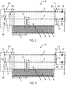
- FIGS. 2 and 3 schematically show a monitoring system 8 according to an embodiment of the invention is designed such that a filled with the transport medium 4 pipe R is automatically monitored and any occurring pipe break 9 is identified and located in a timely manner.
- the monitoring system 8 comprises a measuring device 10, which is connected via a second end 22 of the first measuring line 1 and a second end 23 of the second measuring line 2 to an end switch 11.
- the limit switch 11 includes two grounded blocking diodes 12, wherein in its first switch position 13, it connects the first measuring line 1 at its second end 22 to the second measuring line 2 at its second end 23 ( FIG. 3 ), and in its second switch position 14, the first measuring line 1 at its second end 22 and the second measuring line 2 at its second end 23 with one of the blocking diodes 12 connects ( FIG. 2 ).
- the limit switch 11 is in this case controlled by the measuring device 10 via the first measuring line 1 and / or the second measuring line 2.
- a corresponding detection is based on the fact that for determining the Pipe rupture 9 a threshold resistance at the first measuring line 1 and / or the second measuring line 2 is exceeded, and for detecting a wire break a threshold resistance on the measuring line 1 and / or the measuring line 2 is exceeded.
- the pipe break 9 is in this case detected insofar as due to damage of the plastic pipe 6 and / or the metal tube 5, moisture from the outside or from the inside enters the insulation material 3, and between the first measuring line 1 and / or the second measuring line 2 and grounded metal tube 5 forms an electrically conductive connection.
- the limit switch 11 is controlled to its first switch position 13, thereby connecting the first measuring line 1 to the second measuring line 2 at its second ends 22 and 23.
- the corresponding block diagram is in FIG. 3 shown.
- the pipe break 9 adjusting voltage divider From the measuring voltage 18 and the measuring voltage 20 is then on the pipe break 9 adjusting voltage divider, and with the aid of the lengths of the first measuring line 1, the second measuring line 2 and the metal tube 5, the location of the pipe crack 9, so the distance of the pipe crack 9 determined by the measuring device 10.
- This distance corresponds to the length component L of the measuring line 1 from its first end 19 to the location of the pipe break 9 and is proportional to the measuring voltage 18 that arises.
- the remaining length fraction from the location of the raw fracture 9 to the second end of the first measuring line 22, as well as the length of second measuring line 2 corresponds to the self-adjusting measuring voltage 20.
- the self-adjusting current can be, for example, 5 amperes.
- the accuracy of this distance location for determining the location of the pipe crack 9 is substantially three percent of the total length of the measuring lines used for the measurement.
- FIG. 4 shows the monitoring system 8 according to a further embodiment, in which along the filled with the transport medium 4 pipe R in addition to the measuring device 10 and the Endumschalter 11 two intermediate changeover 24 are provided, which are also each controlled by the measuring device 10 and between a first switch position 25 and a second switch position 26 are switchable.
- each of the intermediate changeover switches 24 in the first switch position 25 connects all of the measuring lines coming from the measuring device 10 or another intermediate changeover switch 24 each with the Endumschalter 11, and includes in the second switch position 26 at least two, coming from the measuring device 10 or another intermediate switch 24 measuring lines short.
- a portable measuring device such as a measuring case, respectively from both sides of the assumed location of the pipe crack 9, so for example, by the measuring device 10 and of the measuring device 10 closest to the connection unit 29, carried out a distance location.
- the respectively adjusting measuring voltages 18 correspond in each case to the length component L from the location of the rough fracture 9 to the portable measuring device. It is measured in each case in positive and negative polarity of the supply voltage 17.
- a positive polarity, or negative polarity, of the supply voltage 17 is present when the first end 19 of the first measuring line 1 is designed as a positive pole, or as a negative pole, and the first end 21 of the second measuring line 2 as a negative pole, or as a positive pole.
- the monitoring system according to the invention can also be used for monitoring other pipelines.
- piping of a cooling system or even an oil or gas line could be monitored.
Abstract
Die Erfindung betrifft ein Überwachungssystem (8) zum Bestimmen des Ortes eines Rohrbruchs (9) einer mit einem Transportmedium (4) gefüllten Rohrleitung (R). Das Isolationsmaterial (3) der Rohrleitung weist eine erste Messleitung (1) und eine zweite Messleitung (2) auf. Das Überwachungssystem (8) weist eine Messeinrichtung (10) auf, die zum Bestimmen des Ortes des Rohrbruchs (9) der Rohrleitung (R) ausgebildet ist, wobei ein Endumschalter (11) an der ersten Messleitung (1) und an der zweiten Messleitung (2) angeschlossen und von der Messeinrichtung (10) gesteuert zwischen einer ersten Schalterstellung (13) und einer zweiten Schalterstellung (14) umschaltbar ist, wobei die zweiten Enden (22; 23) der Messleitungen (1; 2) in der ersten Schalterstellung (13) zum Bestimmen des Ortes des Rohrbruchs (9) verbunden sind und, wobei jedes der zweiten Enden (22; 23) der Messleitungen (1; 2) in der zweiten Schalterstellung (14) über eine in Sperrrichtung gepolte Diode (12) mit dem inneren Metallrohr (5) beziehungsweise Erdpotential verbunden ist.The invention relates to a monitoring system (8) for determining the location of a pipe burst (9) of a pipe (R) filled with a transport medium (4). The insulation material (3) of the pipeline has a first measuring line (1) and a second measuring line (2). The monitoring system (8) has a measuring device (10) which is designed to determine the location of the pipe break (9) of the pipeline (R), wherein an end switch (11) on the first measuring line (1) and on the second measuring line ( 2) connected and controlled by the measuring device (10) between a first switch position (13) and a second switch position (14) is switchable, wherein the second ends (22; 23) of the measuring leads (1; 2) in the first switch position (13 ) are connected to determine the location of the tube break (9) and, wherein each of the second ends (22; 23) of the test leads (1; 2) in the second switch position (14) via a reversely poled diode (12) with the inner Metal tube (5) or ground potential is connected.
Description
Die Erfindung betrifft ein Überwachungssystem zum Bestimmen des Ortes eines Rohrbruchs einer mit einem Transportmedium gefüllten Rohrleitung, die ein äußeres Kunststoffrohr mit einem von Isolationsmaterial umgebenen inneren Metallrohr umfasst, wobei in dem Isolationsmaterial zumindest eine erste Messleitung und eine zweite Messleitung vorgesehen sind und, wobei das Überwachungssystem eine Messeinrichtung aufweist, die mit einem ersten Ende der ersten Messleitung und einem ersten Ende der zweiten Messleitung verbunden und durch Anlegen einer Versorgungsspannung und Messen einer Messspannung an den Messleitungen zum Bestimmen des Ortes des Rohrbruchs der Rohrleitung ausgebildet ist. So ein Rohrbruch bildet eine Fehlerstelle und kann sowohl in der mit dem Transportmedium gefüllten Rohrleitung, beziehungsweise dem Mediumrohr, als auch in dem äußeren Kunststoffrohr, beziehungsweise dem Mantelrohr, auftreten.The invention relates to a monitoring system for determining the location of a pipe burst of a pipeline filled with a transport medium, comprising an outer plastic tube with an inner metal tube surrounded by insulating material, wherein in the insulating material at least a first measuring line and a second measuring line are provided and, wherein the monitoring system a measuring device which is connected to a first end of the first measuring line and a first end of the second measuring line and formed by applying a supply voltage and measuring a measuring voltage to the measuring lines for determining the location of the pipe breakage of the pipeline. Such a pipe break forms a fault and can occur both in the filled with the transport medium pipe, or the medium pipe, as well as in the outer plastic pipe, or the jacket tube.
Das Dokument
Dem Fachmann ist weiters bekannt, dass sich zur Bestimmung des Ortes eines Rohrbruchs am Ende einer jeden Messleitung eine geerdete Diode in Sperrrichtung befinde muss, mit deren Hilfe und durch Anlegen entsprechender Versorgungsspannungen und Messen zugehöriger Messspannungen an den jeweiligen Messleitungen, das Auftreten eines Rohrbuchs und/oder das Auftreten eines Drahtbruchs detektiert werden kann.The person skilled in the art is further aware that in order to determine the location of a pipe break at the end of each measuring line, a grounded diode must be in the reverse direction, with the aid of which and by applying corresponding supply voltages and measuring associated measuring voltages to the respective measuring lines, the occurrence of a pipe book and / or or the occurrence of a wire break can be detected.
Tritt zum Beispiel, durch eine Beschädigung des Kunststoffrohrs und/oder des Metallrohrs, Feuchtigkeit von außen beziehungsweise von innen in den Isolationsraum ein, bildet sich zwischen der Messleitung und dem geerdeten Metallrohr eine elektrisch leitende Verbindung aus, die mittels einer Messeinrichtung detektiert werden kann.Occurs, for example, by damaging the plastic pipe and / or the metal tube, moisture from the outside or from the inside into the insulation space, formed between the measuring line and the grounded metal pipe from an electrically conductive connection, which can be detected by a measuring device.
Wird ein Defekt (Isolationsfehler, Drahtbruch, Rohrbruch) detektiert, werden, durch Anlegen einer Versorgungsspannung an einer der Messleitungen, die sich einstellenden Messspannungen zwischen dem ersten und zweiten Ende der Messleitung sowie zischen dem ersten Ende der Messleitung und dem Metallrohr ermittelt. Im Fall eines Rohrbruchs, wird aus den gemessenen Werten über den, sich am Rohrbruch einstellenden, Spannungsteiler, und unter Zuhilfenahme der Längen von Messleitung und Metallrohr, der Ort des Rohrbruchs ermittelt.If a defect (insulation fault, wire breakage, pipe break) is detected, by applying a supply voltage to one of the test leads, which become established Measuring voltages between the first and second ends of the measuring line and hiss the first end of the measuring line and the metal tube determined. In the case of a pipe burst, the location of the pipe break is determined from the measured values via the voltage divider, which adjusts itself to the pipe break, and with the aid of the lengths of measuring line and metal pipe.
Bei dem bekannten Verfahren hat sich als Nachteil erwiesen, dass ein dauerhaftes Überwachen und zeitnahes Identifizieren eines möglichen Drahtbruchs und/oder eines Rohrbuchs, sowie des dazugehörigen Ortes, nicht kombiniert, automatisiert und dauerhaft durchgeführt werden kann, und daher extrem Zeit- und Ressourcen-intensiv ist.
Der Erfindung liegt die Aufgabe zugrunde ein Überwachungssystem zum Feststellen von Fehlerstellen zu schaffen, bei dem die vorstehenden Nachteile nicht auftreten, und bei dem die Rohrleitung vollautomatisiert überwacht, und etwaig auftretende Defekte (Isolationsfehler, Drahtbruch, Rohrbruch) zeitnah identifiziert und lokalisiert werden können.In the known method has proven to be a disadvantage that a permanent monitoring and timely identification of a possible wire breakage and / or a pipe book, and the associated location, not combined, automated and permanent can be performed, and therefore extremely time and resources intensive is.
The invention has for its object to provide a monitoring system for detecting defects in which the above disadvantages do not occur, and in which the pipeline is monitored fully automated, and any defects occurring (insulation fault, wire breakage, pipe break) can be identified and localized promptly.
Erfindungsgemäß wird diese Aufgabestellung dadurch gelöst, dass ein Endumschalter an einem zweiten Ende der ersten Messleitung und an einem zweiten Ende der zweiten Messleitung angeschlossen und von der Messeinrichtung gesteuert zwischen einer ersten Schalterstellung und einer zweiten Schalterstellung umschaltbar ist, wobei die zweiten Enden der Messleitungen in der ersten Schalterstellung zum Bestimmen des Ortes des Rohrbruchs verbunden sind und, wobei jedes der zweiten Enden der Messleitungen in der zweiten Schalterstellung über eine in Sperrrichtung gepolte Diode mit dem inneren Metallrohr beziehungsweise Erdpotential verbunden ist.According to the invention, this task is solved in that an end switch connected to a second end of the first measuring line and at a second end of the second measuring line and controlled by the measuring device between a first switch position and a second switch position is switchable, wherein the second ends of the measuring lines in the first switch position for determining the location of the pipe rupture are connected, and wherein each of the second ends of the test leads is connected in the second switch position via a reverse-biased diode with the inner metal tube or ground potential.
Hierdurch ist der Vorteil erhalten, dass eine Rohrleitung in wählbaren Intervallen dauerhaft und regelmäßig auf das Auftreten eines Drahtbruchs und/oder eines Rohrbuchs hin überprüft wird. Im tatsächlichen Falle des Auftretens eines Rohrbruchs wird dann - wiederum über die Messeinrichtung gesteuert - der Ort des Rohrbruchs lokalisiert. Konsequenterweise kann der Rohrbruch nachfolgend zeitnah und Ressourcen-schonend behoben werden.This has the advantage that a pipe is permanently and regularly checked for the occurrence of a wire breakage and / or a pipe book at selectable intervals. In the actual case of the occurrence of a pipe break then - again controlled by the measuring device - the location of the pipe break located. Consequently, the pipe break can subsequently be remedied promptly and conserving resources.
Ein weiterer Vorteil des Überwachungssystems besteht darin, dass sehr lange Rohrleitungen bzw. alle Rohrleitungen eines weitverzweigten und ausgedehnten Rohrleitungs-Systems - wie zum Beispiel im Fall eines Fernwärme-Rohrleitungssystem - ebenfalls vollautomatisiert überwacht werden können. Das erfindungsgemäße Überwachungssystem sieht bei solchen Rohrleitungssystemen vor, zwischen Messeinrichtung und Endumschalter (auch: "Connection Endswitch") zumindest einen Zwischenumschalter (auch "Connection Sideswitch") in die Messleitungen zu schalten, der ebenfalls von der Messeinrichtung gesteuert umschaltbar ist. Dabei verfügt der Zwischenumschalter grundsätzlich über dieselben technischen Möglichkeiten wie der Endumschalter, mit der zusätzlichen Option, die ihm nachfolgenden Messleitungen vom ihm vorangehenden Teil des Überwachungssystems frei zu schalten. Je Umschalteinheit können bis zu vier Drähte angeschlossen und überwacht werden. Diese werden bei Fernwärmerohren von den Rohrleitungen der Zuleitungen (auch: "Vorlauf (VL)") beziehungsweise den Rohrleitungen der Ableitungen (auch: "Rücklauf (RL)") zur Verfügung gestellt.A further advantage of the monitoring system is that very long pipelines or all pipelines of a widely branched and extended pipeline system-such as, for example, in the case of a district heating piping system-can also be monitored fully automatically. The monitoring system according to the invention provides for such piping systems, between measuring device and end switch (also: "Connection Endswitch") at least one intermediate switch (also "Connection Sideswitch "), which is also switchable by the measuring device, whereby the intermediate switch basically has the same technical possibilities as the limit switch, with the additional option of switching the subsequent measuring lines from the previous part of the monitoring system. Up to four wires can be connected and monitored per changeover unit, which are provided by the pipelines of the supply lines (also: "flow (VL)" or the pipes of the discharge lines (also: "return line (RL)") for district heating pipes.
Das Vorsehen eines Zwischenumschalters hat den Vorteil, dass die zu messende Länge der Rohrleitung reduziert wird, was wiederum die Ungenauigkeit der Bestimmung des Ortes des Rohrbruchs - in diesem Fall die Entfernung des Rohrbruchs zur Messeinrichtung - reduziert. Dies ergibt sich daraus, da die absolute Größe der Ungenauigkeit der Bestimmung des Ortes des Rohrbruchs von der Gesamtlänge der Rohrleitung abhängt, und bei konstantem Verhältnis in etwa linear mit steigender Gesamtlänge zunimmt.The provision of an intermediate changeover switch has the advantage that the length of the pipeline to be measured is reduced, which in turn reduces the inaccuracy of determining the location of the pipe rupture - in this case the removal of the pipe rupture to the measuring device. This is because the absolute magnitude of the inaccuracy of determining the location of the pipe break depends on the overall length of the pipeline, and increases at a constant ratio approximately linearly with increasing total length.
Im konkreten Fall eines Fernwärme-Rohrleitungssystems bietet die Erfindung den Vorteil, dass die Rohrleitung vom Heizkraftwerk zu einem einzelnen Hausanschluss messtechnisch isoliert werden kann, um einen etwaigen Rohrbruch an dieser Verbindung festzustellen und zu lokalisieren. Das Überwachungssystem erlaubt, die Rohrleitungen der Zuleitungen wie auch die Rohrleitungen der Ableitungen, vollautomatisiert zu überwachen, und jede der vorhandenen Messleitungen als Steuerungsmittel zu verwenden. Darüber hinaus kann eine beliebige Anzahl von Anschlusseinheiten, zum Beispiel in jedem Haus, installiert werden, die den Anschluss eines Messgerätes und/oder weiterer Messleitungen an die Messleitungen des Überwachungssystems erlauben.In the specific case of a district heating piping system, the invention offers the advantage that the pipeline from the heating plant to a single house connection can be metrologically isolated in order to determine and locate any pipe break at this connection. The monitoring system makes it possible to fully automatically monitor the pipes of the supply lines as well as the pipes of the discharge lines, and to use each of the existing measuring lines as control means. In addition, any number of connection units, for example, in each house, can be installed, which allow the connection of a measuring device and / or further measuring lines to the measuring lines of the monitoring system.
Weitere vorteilhafte Ausgestaltungen des erfindungsgemäßen Überwachungssystems werden im Folgenden anhand der Figuren näher erläutert.
-
Figur 1 -
Figur 2 -
Figur 3 -
Figur 4 -
Figur 5 -
Figur 6
-
FIG. 1 shows schematically a cross section of a pipeline, wherein two measuring lines are introduced into an insulating material between an inner metal tube and an outer plastic tube. -
FIG. 2 shows a schematic and block diagram of a monitoring system for detecting a pipe crack according to a first embodiment of the invention. -
FIG. 3 shows a schematic and block diagram of a monitoring system for detecting a pipe crack according to a first embodiment of the invention. -
FIG. 4 shows a schematic and a block diagram of a monitoring system for Determining a pipe crack according to another embodiment of the invention. -
FIG. 5 Fig. 10 is a table showing resistance values for a copper wire having a diameter of 1.5 mm 2 depending on the wire temperature. -
FIG. 6 shows a block diagram of a monitoring system for detecting a pipe crack according to another embodiment of the invention.
Die Überwachung der Rohrleitung R geschieht bei der vorliegenden Erfindung insofern vorteilhaft, dass im Fall der zweiten Schalterstellung 14 des Endumschalters 11 laut
Der Rohrbruch 9 wird hierbei insofern detektiert, da durch eine Beschädigung des Kunststoffrohrs 6 und/oder des Metallrohrs 5, Feuchtigkeit von außen beziehungsweise von innen in das Isolationsmaterial 3 eintritt, und sich zwischen der ersten Messleitung 1 und/oder der zweiten Messleitung 2 und dem geerdeten Metallrohr 5 eine elektrisch leitende Verbindung ausbildet.The
Um den Ort des Rohrbruchs 9 zu bestimmen, wird der Endumschalter 11 in seine erste Schalterstellung 13 gesteuert, und dadurch die erste Messleitung 1 mit der zweiten Messleitung 2 an ihren zweiten Enden 22 und 23 verbunden. Das entsprechende Blockschaltbild ist in
Dies ist deshalb von entscheidendem Vorteil, da bei weit verzweigten und/oder ausgedehnten Fernwärme-Rohrleitungssystemen 7 die exakte Bestimmung des Ortes des Rohrbruchs 9 schwierig ist. Um den Ort des Rohrbruchs 9 möglichst genau zu bestimmen, werden über die Messeinrichtung 10 gesteuert, sukzessive bei jedem Zwischenumschalter 24 in der ersten Schalterstellung 25 die Messleitungen geöffnet, und das Feststellen des Rohrbruchs durchgeführt, wobei als erstes über den Endumschalter 11 getestet wird, dann über den der Messeinrichtung 10 räumlich am weitesten entfernt liegenden Zwischenumschalter 24, dann über den der Messeinrichtung 10 nächst näher gelegenen Zwischenumschalter 24, usw. Ist der der Messeinrichtung 10 am nächsten gelegenen Zwischenumschalter 24, bis zu dem der Rohrbruch 9 noch detektierbar ist, identifiziert, so wird dieser in seine zweite Schalterstellung 26 gesteuert, um den Ort des Rohrbruchs 9 zu lokalisieren. Da die Genauigkeit dieser Distanzortung zur Bestimmung des Ortes des Rohrbruchs 9 im Wesentlichen drei Prozent der Gesamtlänge der zur Messung verwendeten Messleitungen beträgt, kann so Größe des Messfehlers erheblich reduziert werden, da die Gesamtlänge der zur Messung verwendeten Messleitungen reduziert wird.This is therefore of decisive advantage, because with widely branched and / or extensive district heating piping systems 7 the exact determination of the location of the
Liegt der Rohrbruch 9 beispielsweise im Bereich einer abzweigenden Zuleitung oder Ableitung zu einem Haus, wird die zugehörige Rohrleitung R durch Steuern und Schalten des entsprechenden Zwischenumschalters 24 isoliert, und so eine Identifizierung und Lokalisierung des Rohrbruchs 9 erst ermöglicht.
Um den Ort des Rohrbruchs exakt zu bestimmen, wird mittels einer tragbaren Messvorrichtung, beispielsweise einem Messkoffer, jeweils von beiden Seiten des vermuteten Ortes des Rohrbruchs 9, also beispielsweise von der Messeinrichtung 10 und von der der Messeinrichtung 10 am nächsten gelegenen Anschlusseinheit 29, eine Distanzortung durchgeführt. Die sich hierbei jeweils einstellenden Messspannungen 18 entsprechen jeweils dem Längenanteil L vom Ort des Rohbruchs 9 zur tragbaren Messvorrichtung. Es wird jeweils in positiver und negativer Polung der Versorgungsspannung 17 gemessen. Eine positive Polung, beziehungsweise negative Polung, der Versorgungsspannung 17 liegt vor, wenn das erste Ende 19 der ersten Messleitung 1 als Pluspol, beziehungsweise als Minuspol, und das erste Ende 21 der zweiten Messleitung 2 als Minuspol, beziehungsweise als Pluspol, ausgebildet ist. Bei positiver Polung, beziehungsweise negativer Polung, der Versorgungsspannung 17 stellt sich zwischen dem erste Ende 19 der ersten Messleitung 1 und dem Metallrohr 5 eine Spannung U1+, beziehungsweise eine Spannung U1-, ein. Die Spannung U1+, beziehungsweise die Spannung U1-, entspricht somit der Messspannung 18 bei positiver Polung, beziehungsweise negativer Polung, der Versorgungsspannung 17. Mittels der Berechnungsformel Messspannung 18 = (U1+ U1-)/2 wird eine "Fremdspannungskorrektur" der Messspannung 18 durchgeführt. Des weiteren wird eine "Fehlerwiderstandskorrektur" der sich jeweils einstellenden Messspannungen 18 hinsichtlich des Innenwiderstands der Rohrleitung durchgeführt. Schließlich werden die sich jeweils einstellenden Messspannungen 18 bezüglich der Drahttemperatur der Messleitung 1 oder der Messleitung 2 korrigiert. Eine entsprechende Tabelle, die Widerstandswerte für einen Kupferdraht mir einem Durchmesser von 1,5 mm2 in Abhängigkeit von der Drahttemperatur wiedergibt, ist in
Das Überwachungssystem 8, beziehungsweise eine damit durchgeführte Ortung im Falle eines Rohrbruchs 9, kann folgend zusammengefasst werden:
- 1. Drahtbruchüberwachung:
Endumschalter 11 befindet sich in seiner zweiten Schalterstellung 14, dieSperrdioden 12 werden mit dem Erdpotential verbunden und die, dieSperrdioden 12 in Durchlassrichtung ansteuernde, gegenpolige Spannung 16 wird angelegt. - 2. Überwachung des Isolationswiderstandes hinsichtlich des Eindringens von Feuchtigkeit, beziehungsweise eines Rohrbruchs 9: Endumschalter 11 befindet sich in seiner ersten Schalterstellung 13 und die, die
Sperrdioden 12 in Sperrrichtung ansteuernde,Spannung 15 wird angelegt. - 3. Vorortung der Leckstelle mit Fehlerkorrekturverfahren beziehungsweise Feststellen des Ortes des
Rohrbruchs 9, laut zuvor beschriebenen Ausführungsbeispielen, mit im Wesentlichen +/- 3 Prozent Fehlergenauigkeit. - 4. Leckstellenfeinortung beziehungsweise Feststellen des Ortes des Rohrbruchs 9 mit der tragbaren Messvorrichtung und Fehlerkorrekturverfahren, wobei sich ein Messtechniker an der nächstgelegenen Anschlusseinheit 29 befindet, laut zuvor beschriebenen Ausführungsbeispielen, mit im Wesentlichen +/- 1 Prozent Fehlergenauigkeit.
- 1. Wire break monitoring:
Endumschalter 11 is in itssecond switch position 14, the blockingdiodes 12 are connected to the ground potential and the, the blockingdiodes 12 in the forward direction driving,opposite polarity voltage 16 is applied. - 2. Monitoring the insulation resistance with respect to the penetration of moisture, or a pipe break 9: Endumschalter 11 is in its
first switch position 13 and, the blockingdiodes 12 driving in the reverse direction,voltage 15 is applied. - 3. Pre-location of the leak with error correction method or determining the location of the
pipe crack 9, according to previously described embodiments, with substantially +/- 3 percent error accuracy. - 4. Leak location fine detection or determination of the location of the
pipe crack 9 with the portable measuring device and error correction method, which is a Messtechniker located at thenearest terminal unit 29, according to previously described embodiments, with substantially +/- 1 percent error accuracy.
Es kann erwähnt werden, dass das erfindungsgemäße Überwachungssystem auch zum Überwachen von anderen Rohrleitungen genutzt werden kann. Hierbei könnten beispielsweise Rohrleitungen eines Kühlsystems oder auch einer Öl- oder Gasleitung überwacht werden. Weiters wäre es möglich in einer Rohrleitung auch mehr als nur zwei Messleitungen vorzusehen.It can be mentioned that the monitoring system according to the invention can also be used for monitoring other pipelines. In this case, for example, piping of a cooling system or even an oil or gas line could be monitored. Furthermore, it would be possible to provide more than just two measuring lines in a pipeline.
Claims (10)
dadurch gekennzeichnet, dass
ein Endumschalter (11) an einem zweiten Ende (22) der ersten Messleitung (1) und an einem zweiten Ende (23) der zweiten Messleitung (2) angeschlossen und von der Messeinrichtung (10) gesteuert zwischen einer ersten Schalterstellung (13) und einer zweiten Schalterstellung (14) umschaltbar ist, wobei die zweiten Enden (22, 23) der Messleitungen (1, 2) in der ersten Schalterstellung (13) zum Bestimmen des Ortes des Rohrbruchs (9) verbunden sind und, wobei jedes der zweiten Enden (22, 23) der Messleitungen (1, 2) in der zweiten Schalterstellung (14) über eine in Sperrrichtung gepolte Diode (12) mit dem inneren Metallrohr (5) beziehungsweise Erdpotential verbunden ist.Monitoring system (8) for determining the location of a pipe break (9) of a pipe (R) filled with a transport medium (4) comprising an outer plastic pipe (6) with an inner metal pipe (5) surrounded by insulating material (3) at least one first measuring line (1) and one second measuring line (2) are provided in the insulating material (3), the monitoring system (8) having a measuring device (10) connected to a first end (19) of the first measuring line (1). and a first end (21) of the second measuring line (2) and by applying a supply voltage (17) and measuring a measuring voltage (18, 20) on the measuring lines (1, 2) for determining the location of the pipe break (9) of the pipeline (R) is formed
characterized in that
an end switch (11) connected to a second end (22) of the first measuring line (1) and to a second end (23) of the second measuring line (2) and controlled by the measuring device (10) between a first switch position (13) and a second switch position (14) is switchable, wherein the second ends (22, 23) of the measuring lines (1, 2) in the first switch position (13) for determining the location of the pipe break (9) are connected and, wherein each of the second ends ( 22, 23) of the measuring lines (1, 2) in the second switch position (14) is connected via a reversely polarized diode (12) to the inner metal tube (5) or ground potential.
Priority Applications (2)
| Application Number | Priority Date | Filing Date | Title |
|---|---|---|---|
| PL16165031T PL3101403T3 (en) | 2015-04-24 | 2016-04-13 | Monitoring system for the detection of faults in pipelines |
| SI201630012T SI3101403T1 (en) | 2015-04-24 | 2016-04-13 | Monitoring system for the detection of faults in pipelines |
Applications Claiming Priority (1)
| Application Number | Priority Date | Filing Date | Title |
|---|---|---|---|
| ATGM50072/2015U AT14914U1 (en) | 2015-04-24 | 2015-04-24 | Monitoring system for detecting faults in pipelines |
Publications (2)
| Publication Number | Publication Date |
|---|---|
| EP3101403A1 true EP3101403A1 (en) | 2016-12-07 |
| EP3101403B1 EP3101403B1 (en) | 2017-09-13 |
Family
ID=56564978
Family Applications (1)
| Application Number | Title | Priority Date | Filing Date |
|---|---|---|---|
| EP16165031.2A Active EP3101403B1 (en) | 2015-04-24 | 2016-04-13 | Monitoring system for the detection of faults in pipelines |
Country Status (5)
| Country | Link |
|---|---|
| EP (1) | EP3101403B1 (en) |
| AT (1) | AT14914U1 (en) |
| HU (1) | HUE035161T2 (en) |
| PL (1) | PL3101403T3 (en) |
| SI (1) | SI3101403T1 (en) |
Cited By (1)
| Publication number | Priority date | Publication date | Assignee | Title |
|---|---|---|---|---|
| WO2022224221A1 (en) * | 2021-04-23 | 2022-10-27 | Danfoss Power Solutions Ii Technology A/S | Hose sensor assembly including direct sensor integration integration with monitoring circuitry |
Citations (3)
| Publication number | Priority date | Publication date | Assignee | Title |
|---|---|---|---|---|
| DE4003788A1 (en) * | 1990-02-08 | 1991-08-14 | Salzgitter Elektronik Gmbh | Two wire line monitoring system - using measured loop and insulation resistances for pipe network leakage detection |
| EP1031826A2 (en) | 1999-02-25 | 2000-08-30 | Curt Reichert | Procedure for detecting the position of a leak |
| US20090277252A1 (en) * | 2008-05-06 | 2009-11-12 | Joongang Control Co., Ltd. | Leakage detecting apparatus |
Family Cites Families (2)
| Publication number | Priority date | Publication date | Assignee | Title |
|---|---|---|---|---|
| AT388430B (en) * | 1987-05-06 | 1989-06-26 | Scheuermann Herbert Dipl Ing | DEVICE FOR DETECTING AND LOCATING LEAKS IN A PIPING LINE CARRYING A DAMP MEDIUM |
| EP0417061B1 (en) * | 1989-09-05 | 1994-03-02 | Brandes, Bernd | Procedure and apparatus for locating the true leakage point of a pipeline guided in a wet medium |
-
2015
- 2015-04-24 AT ATGM50072/2015U patent/AT14914U1/en unknown
-
2016
- 2016-04-13 PL PL16165031T patent/PL3101403T3/en unknown
- 2016-04-13 HU HUE16165031A patent/HUE035161T2/en unknown
- 2016-04-13 EP EP16165031.2A patent/EP3101403B1/en active Active
- 2016-04-13 SI SI201630012T patent/SI3101403T1/en unknown
Patent Citations (3)
| Publication number | Priority date | Publication date | Assignee | Title |
|---|---|---|---|---|
| DE4003788A1 (en) * | 1990-02-08 | 1991-08-14 | Salzgitter Elektronik Gmbh | Two wire line monitoring system - using measured loop and insulation resistances for pipe network leakage detection |
| EP1031826A2 (en) | 1999-02-25 | 2000-08-30 | Curt Reichert | Procedure for detecting the position of a leak |
| US20090277252A1 (en) * | 2008-05-06 | 2009-11-12 | Joongang Control Co., Ltd. | Leakage detecting apparatus |
Cited By (1)
| Publication number | Priority date | Publication date | Assignee | Title |
|---|---|---|---|---|
| WO2022224221A1 (en) * | 2021-04-23 | 2022-10-27 | Danfoss Power Solutions Ii Technology A/S | Hose sensor assembly including direct sensor integration integration with monitoring circuitry |
Also Published As
| Publication number | Publication date |
|---|---|
| AT14914U1 (en) | 2016-08-15 |
| SI3101403T1 (en) | 2018-01-31 |
| EP3101403B1 (en) | 2017-09-13 |
| HUE035161T2 (en) | 2018-05-02 |
| PL3101403T3 (en) | 2018-02-28 |
Similar Documents
| Publication | Publication Date | Title |
|---|---|---|
| DE3930530C2 (en) | ||
| AT501758A4 (en) | METHOD OF LOCATING LEAKAGE IN TUBE | |
| DE102012019996A1 (en) | Line network, in particular DC vehicle electrical system for a motor vehicle and method for monitoring a pipeline network to the emergence of an arc | |
| WO2007006695A1 (en) | Measuring device for determining and/or monitoring a process variable and method for monitoring said measuring device | |
| EP0060552B1 (en) | Apparatus for monitoring a canalisation system, especially an isolated heating canalisation for long distances | |
| DE2337983C2 (en) | Location and monitoring circuit | |
| WO2015091170A1 (en) | Leak-monitoring system for space-enclosing objects and coupling regions lying therebetween, as well as an associated method | |
| EP2988139A1 (en) | Monitoring system for an electric power cable, electric power cable for such a monitoring system and method for monitoring an electric power cable with the aid of such a monitoring system | |
| DE102018202010A1 (en) | A method for predicting impending damage to a joint between two electrical conductors in a motor vehicle electrical system, apparatus and motor vehicle | |
| EP3101403B1 (en) | Monitoring system for the detection of faults in pipelines | |
| EP2112491B1 (en) | Device, system and method for detecting and locating leakages | |
| DE3225742A1 (en) | Circuit arrangement for determining leakage points in insulated pipelines | |
| EP3872503A1 (en) | Monitoring device and method for monitoring the insulation of an unshielded electrical system with grounded liquid cooling | |
| DE2322085A1 (en) | FLUID-FILLED ELECTRIC CABLE | |
| DE102017205886A1 (en) | Device with wearing part and measuring device for wear | |
| DE202018106981U1 (en) | Arrangement comprising a pipeline and a device for monitoring thereof | |
| DE102021124432B4 (en) | Ground fault detection device for detecting a ground fault in a low-voltage cable network | |
| EP3336508A1 (en) | Meter device, meter system and method for operating a meter device | |
| EP3449244B1 (en) | Arrangement and method for detecting damage to an inner coating of a container | |
| EP1728895A1 (en) | Surveillance method for detecting the approach of a conductive body to a cathodically protected pipeline for fluids | |
| EP2251179B1 (en) | Device for inspecting a wire coating | |
| DE10257330A1 (en) | High voltage cable and pipe precision sheath water penetration fault detection and location procedure compares voltages measured between sensor cable and ground cable for constant current | |
| DE112019006931T5 (en) | Crack sensor system | |
| EP3247984B1 (en) | Device and method for sensing temperature, as well as use of the device | |
| DE202008006899U1 (en) | Device for detecting temperatures in areas of a technical installation |
Legal Events
| Date | Code | Title | Description |
|---|---|---|---|
| PUAI | Public reference made under article 153(3) epc to a published international application that has entered the european phase |
Free format text: ORIGINAL CODE: 0009012 |
|
| STAA | Information on the status of an ep patent application or granted ep patent |
Free format text: STATUS: THE APPLICATION HAS BEEN PUBLISHED |
|
| AK | Designated contracting states |
Kind code of ref document: A1 Designated state(s): AL AT BE BG CH CY CZ DE DK EE ES FI FR GB GR HR HU IE IS IT LI LT LU LV MC MK MT NL NO PL PT RO RS SE SI SK SM TR |
|
| AX | Request for extension of the european patent |
Extension state: BA ME |
|
| STAA | Information on the status of an ep patent application or granted ep patent |
Free format text: STATUS: REQUEST FOR EXAMINATION WAS MADE |
|
| 17P | Request for examination filed |
Effective date: 20161230 |
|
| RBV | Designated contracting states (corrected) |
Designated state(s): AL AT BE BG CH CY CZ DE DK EE ES FI FR GB GR HR HU IE IS IT LI LT LU LV MC MK MT NL NO PL PT RO RS SE SI SK SM TR |
|
| GRAP | Despatch of communication of intention to grant a patent |
Free format text: ORIGINAL CODE: EPIDOSNIGR1 |
|
| STAA | Information on the status of an ep patent application or granted ep patent |
Free format text: STATUS: GRANT OF PATENT IS INTENDED |
|
| RIC1 | Information provided on ipc code assigned before grant |
Ipc: G01M 3/16 20060101AFI20170221BHEP Ipc: F16L 59/14 20060101ALI20170221BHEP Ipc: G01M 3/18 20060101ALI20170221BHEP |
|
| INTG | Intention to grant announced |
Effective date: 20170328 |
|
| GRAS | Grant fee paid |
Free format text: ORIGINAL CODE: EPIDOSNIGR3 |
|
| GRAA | (expected) grant |
Free format text: ORIGINAL CODE: 0009210 |
|
| STAA | Information on the status of an ep patent application or granted ep patent |
Free format text: STATUS: THE PATENT HAS BEEN GRANTED |
|
| AK | Designated contracting states |
Kind code of ref document: B1 Designated state(s): AL AT BE BG CH CY CZ DE DK EE ES FI FR GB GR HR HU IE IS IT LI LT LU LV MC MK MT NL NO PL PT RO RS SE SI SK SM TR |
|
| REG | Reference to a national code |
Ref country code: GB Ref legal event code: FG4D Free format text: NOT ENGLISH |
|
| REG | Reference to a national code |
Ref country code: CH Ref legal event code: EP |
|
| REG | Reference to a national code |
Ref country code: IE Ref legal event code: FG4D Free format text: LANGUAGE OF EP DOCUMENT: GERMAN |
|
| REG | Reference to a national code |
Ref country code: AT Ref legal event code: REF Ref document number: 928628 Country of ref document: AT Kind code of ref document: T Effective date: 20171015 |
|
| REG | Reference to a national code |
Ref country code: DE Ref legal event code: R096 Ref document number: 502016000133 Country of ref document: DE |
|
| REG | Reference to a national code |
Ref country code: CH Ref legal event code: NV Representative=s name: BOHEST AG, CH |
|
| REG | Reference to a national code |
Ref country code: NL Ref legal event code: MP Effective date: 20170913 |
|
| REG | Reference to a national code |
Ref country code: LT Ref legal event code: MG4D |
|
| PG25 | Lapsed in a contracting state [announced via postgrant information from national office to epo] |
Ref country code: HR Free format text: LAPSE BECAUSE OF FAILURE TO SUBMIT A TRANSLATION OF THE DESCRIPTION OR TO PAY THE FEE WITHIN THE PRESCRIBED TIME-LIMIT Effective date: 20170913 Ref country code: LT Free format text: LAPSE BECAUSE OF FAILURE TO SUBMIT A TRANSLATION OF THE DESCRIPTION OR TO PAY THE FEE WITHIN THE PRESCRIBED TIME-LIMIT Effective date: 20170913 Ref country code: SE Free format text: LAPSE BECAUSE OF FAILURE TO SUBMIT A TRANSLATION OF THE DESCRIPTION OR TO PAY THE FEE WITHIN THE PRESCRIBED TIME-LIMIT Effective date: 20170913 Ref country code: FI Free format text: LAPSE BECAUSE OF FAILURE TO SUBMIT A TRANSLATION OF THE DESCRIPTION OR TO PAY THE FEE WITHIN THE PRESCRIBED TIME-LIMIT Effective date: 20170913 Ref country code: NO Free format text: LAPSE BECAUSE OF FAILURE TO SUBMIT A TRANSLATION OF THE DESCRIPTION OR TO PAY THE FEE WITHIN THE PRESCRIBED TIME-LIMIT Effective date: 20171213 |
|
| PG25 | Lapsed in a contracting state [announced via postgrant information from national office to epo] |
Ref country code: GR Free format text: LAPSE BECAUSE OF FAILURE TO SUBMIT A TRANSLATION OF THE DESCRIPTION OR TO PAY THE FEE WITHIN THE PRESCRIBED TIME-LIMIT Effective date: 20171214 Ref country code: ES Free format text: LAPSE BECAUSE OF FAILURE TO SUBMIT A TRANSLATION OF THE DESCRIPTION OR TO PAY THE FEE WITHIN THE PRESCRIBED TIME-LIMIT Effective date: 20170913 Ref country code: BG Free format text: LAPSE BECAUSE OF FAILURE TO SUBMIT A TRANSLATION OF THE DESCRIPTION OR TO PAY THE FEE WITHIN THE PRESCRIBED TIME-LIMIT Effective date: 20171213 Ref country code: LV Free format text: LAPSE BECAUSE OF FAILURE TO SUBMIT A TRANSLATION OF THE DESCRIPTION OR TO PAY THE FEE WITHIN THE PRESCRIBED TIME-LIMIT Effective date: 20170913 Ref country code: RS Free format text: LAPSE BECAUSE OF FAILURE TO SUBMIT A TRANSLATION OF THE DESCRIPTION OR TO PAY THE FEE WITHIN THE PRESCRIBED TIME-LIMIT Effective date: 20170913 |
|
| PG25 | Lapsed in a contracting state [announced via postgrant information from national office to epo] |
Ref country code: NL Free format text: LAPSE BECAUSE OF FAILURE TO SUBMIT A TRANSLATION OF THE DESCRIPTION OR TO PAY THE FEE WITHIN THE PRESCRIBED TIME-LIMIT Effective date: 20170913 |
|
| REG | Reference to a national code |
Ref country code: FR Ref legal event code: PLFP Year of fee payment: 3 |
|
| PG25 | Lapsed in a contracting state [announced via postgrant information from national office to epo] |
Ref country code: CZ Free format text: LAPSE BECAUSE OF FAILURE TO SUBMIT A TRANSLATION OF THE DESCRIPTION OR TO PAY THE FEE WITHIN THE PRESCRIBED TIME-LIMIT Effective date: 20170913 |
|
| REG | Reference to a national code |
Ref country code: HU Ref legal event code: AG4A Ref document number: E035161 Country of ref document: HU |
|
| PG25 | Lapsed in a contracting state [announced via postgrant information from national office to epo] |
Ref country code: SM Free format text: LAPSE BECAUSE OF FAILURE TO SUBMIT A TRANSLATION OF THE DESCRIPTION OR TO PAY THE FEE WITHIN THE PRESCRIBED TIME-LIMIT Effective date: 20170913 Ref country code: IS Free format text: LAPSE BECAUSE OF FAILURE TO SUBMIT A TRANSLATION OF THE DESCRIPTION OR TO PAY THE FEE WITHIN THE PRESCRIBED TIME-LIMIT Effective date: 20180113 Ref country code: SK Free format text: LAPSE BECAUSE OF FAILURE TO SUBMIT A TRANSLATION OF THE DESCRIPTION OR TO PAY THE FEE WITHIN THE PRESCRIBED TIME-LIMIT Effective date: 20170913 Ref country code: EE Free format text: LAPSE BECAUSE OF FAILURE TO SUBMIT A TRANSLATION OF THE DESCRIPTION OR TO PAY THE FEE WITHIN THE PRESCRIBED TIME-LIMIT Effective date: 20170913 |
|
| REG | Reference to a national code |
Ref country code: DE Ref legal event code: R097 Ref document number: 502016000133 Country of ref document: DE |
|
| PLBE | No opposition filed within time limit |
Free format text: ORIGINAL CODE: 0009261 |
|
| STAA | Information on the status of an ep patent application or granted ep patent |
Free format text: STATUS: NO OPPOSITION FILED WITHIN TIME LIMIT |
|
| PG25 | Lapsed in a contracting state [announced via postgrant information from national office to epo] |
Ref country code: DK Free format text: LAPSE BECAUSE OF FAILURE TO SUBMIT A TRANSLATION OF THE DESCRIPTION OR TO PAY THE FEE WITHIN THE PRESCRIBED TIME-LIMIT Effective date: 20170913 |
|
| 26N | No opposition filed |
Effective date: 20180614 |
|
| PG25 | Lapsed in a contracting state [announced via postgrant information from national office to epo] |
Ref country code: MT Free format text: LAPSE BECAUSE OF FAILURE TO SUBMIT A TRANSLATION OF THE DESCRIPTION OR TO PAY THE FEE WITHIN THE PRESCRIBED TIME-LIMIT Effective date: 20170913 |
|
| PG25 | Lapsed in a contracting state [announced via postgrant information from national office to epo] |
Ref country code: MC Free format text: LAPSE BECAUSE OF FAILURE TO SUBMIT A TRANSLATION OF THE DESCRIPTION OR TO PAY THE FEE WITHIN THE PRESCRIBED TIME-LIMIT Effective date: 20170913 |
|
| REG | Reference to a national code |
Ref country code: BE Ref legal event code: MM Effective date: 20180430 |
|
| REG | Reference to a national code |
Ref country code: IE Ref legal event code: MM4A |
|
| PG25 | Lapsed in a contracting state [announced via postgrant information from national office to epo] |
Ref country code: LU Free format text: LAPSE BECAUSE OF NON-PAYMENT OF DUE FEES Effective date: 20180413 |
|
| PG25 | Lapsed in a contracting state [announced via postgrant information from national office to epo] |
Ref country code: BE Free format text: LAPSE BECAUSE OF NON-PAYMENT OF DUE FEES Effective date: 20180430 |
|
| PG25 | Lapsed in a contracting state [announced via postgrant information from national office to epo] |
Ref country code: IE Free format text: LAPSE BECAUSE OF NON-PAYMENT OF DUE FEES Effective date: 20180413 |
|
| PG25 | Lapsed in a contracting state [announced via postgrant information from national office to epo] |
Ref country code: TR Free format text: LAPSE BECAUSE OF FAILURE TO SUBMIT A TRANSLATION OF THE DESCRIPTION OR TO PAY THE FEE WITHIN THE PRESCRIBED TIME-LIMIT Effective date: 20170913 |
|
| PG25 | Lapsed in a contracting state [announced via postgrant information from national office to epo] |
Ref country code: PT Free format text: LAPSE BECAUSE OF FAILURE TO SUBMIT A TRANSLATION OF THE DESCRIPTION OR TO PAY THE FEE WITHIN THE PRESCRIBED TIME-LIMIT Effective date: 20170913 |
|
| PG25 | Lapsed in a contracting state [announced via postgrant information from national office to epo] |
Ref country code: RO Free format text: LAPSE BECAUSE OF FAILURE TO SUBMIT A TRANSLATION OF THE DESCRIPTION OR TO PAY THE FEE WITHIN THE PRESCRIBED TIME-LIMIT Effective date: 20170913 Ref country code: MK Free format text: LAPSE BECAUSE OF NON-PAYMENT OF DUE FEES Effective date: 20170913 Ref country code: CY Free format text: LAPSE BECAUSE OF FAILURE TO SUBMIT A TRANSLATION OF THE DESCRIPTION OR TO PAY THE FEE WITHIN THE PRESCRIBED TIME-LIMIT Effective date: 20170913 |
|
| PG25 | Lapsed in a contracting state [announced via postgrant information from national office to epo] |
Ref country code: AL Free format text: LAPSE BECAUSE OF FAILURE TO SUBMIT A TRANSLATION OF THE DESCRIPTION OR TO PAY THE FEE WITHIN THE PRESCRIBED TIME-LIMIT Effective date: 20170913 |
|
| GBPC | Gb: european patent ceased through non-payment of renewal fee |
Effective date: 20200413 |
|
| PG25 | Lapsed in a contracting state [announced via postgrant information from national office to epo] |
Ref country code: GB Free format text: LAPSE BECAUSE OF NON-PAYMENT OF DUE FEES Effective date: 20200413 |
|
| REG | Reference to a national code |
Ref country code: AT Ref legal event code: MM01 Ref document number: 928628 Country of ref document: AT Kind code of ref document: T Effective date: 20210413 |
|
| PG25 | Lapsed in a contracting state [announced via postgrant information from national office to epo] |
Ref country code: AT Free format text: LAPSE BECAUSE OF NON-PAYMENT OF DUE FEES Effective date: 20210413 |
|
| PGFP | Annual fee paid to national office [announced via postgrant information from national office to epo] |
Ref country code: IT Payment date: 20230428 Year of fee payment: 8 Ref country code: FR Payment date: 20230417 Year of fee payment: 8 Ref country code: DE Payment date: 20230418 Year of fee payment: 8 Ref country code: CH Payment date: 20230502 Year of fee payment: 8 |
|
| PGFP | Annual fee paid to national office [announced via postgrant information from national office to epo] |
Ref country code: SI Payment date: 20230331 Year of fee payment: 8 Ref country code: PL Payment date: 20230404 Year of fee payment: 8 Ref country code: HU Payment date: 20230411 Year of fee payment: 8 |