EP3101397A1 - Tester for fluid monitors - Google Patents
Tester for fluid monitors Download PDFInfo
- Publication number
- EP3101397A1 EP3101397A1 EP16020211.5A EP16020211A EP3101397A1 EP 3101397 A1 EP3101397 A1 EP 3101397A1 EP 16020211 A EP16020211 A EP 16020211A EP 3101397 A1 EP3101397 A1 EP 3101397A1
- Authority
- EP
- European Patent Office
- Prior art keywords
- tester
- fluid
- selector switches
- fuel
- state
- Prior art date
- Legal status (The legal status is an assumption and is not a legal conclusion. Google has not performed a legal analysis and makes no representation as to the accuracy of the status listed.)
- Granted
Links
- 239000012530 fluid Substances 0.000 title claims abstract description 86
- 238000012544 monitoring process Methods 0.000 claims abstract description 61
- 239000000446 fuel Substances 0.000 claims abstract description 41
- 230000003287 optical effect Effects 0.000 claims description 19
- 238000012546 transfer Methods 0.000 claims description 7
- 239000000463 material Substances 0.000 claims description 3
- XLYOFNOQVPJJNP-UHFFFAOYSA-N water Substances O XLYOFNOQVPJJNP-UHFFFAOYSA-N 0.000 claims description 2
- 238000012360 testing method Methods 0.000 description 21
- 238000000034 method Methods 0.000 description 11
- 239000002360 explosive Substances 0.000 description 5
- 238000005429 filling process Methods 0.000 description 4
- 230000004044 response Effects 0.000 description 4
- 238000004088 simulation Methods 0.000 description 4
- VGGSQFUCUMXWEO-UHFFFAOYSA-N Ethene Chemical compound C=C VGGSQFUCUMXWEO-UHFFFAOYSA-N 0.000 description 3
- 239000005977 Ethylene Substances 0.000 description 3
- 230000001419 dependent effect Effects 0.000 description 3
- 239000007789 gas Substances 0.000 description 3
- 239000000126 substance Substances 0.000 description 3
- ATUOYWHBWRKTHZ-UHFFFAOYSA-N Propane Chemical compound CCC ATUOYWHBWRKTHZ-UHFFFAOYSA-N 0.000 description 2
- 238000010586 diagram Methods 0.000 description 2
- 230000003068 static effect Effects 0.000 description 2
- VYZAMTAEIAYCRO-UHFFFAOYSA-N Chromium Chemical compound [Cr] VYZAMTAEIAYCRO-UHFFFAOYSA-N 0.000 description 1
- UFHFLCQGNIYNRP-UHFFFAOYSA-N Hydrogen Chemical compound [H][H] UFHFLCQGNIYNRP-UHFFFAOYSA-N 0.000 description 1
- HSFWRNGVRCDJHI-UHFFFAOYSA-N alpha-acetylene Natural products C#C HSFWRNGVRCDJHI-UHFFFAOYSA-N 0.000 description 1
- 230000004075 alteration Effects 0.000 description 1
- QVGXLLKOCUKJST-UHFFFAOYSA-N atomic oxygen Chemical compound [O] QVGXLLKOCUKJST-UHFFFAOYSA-N 0.000 description 1
- 238000004891 communication Methods 0.000 description 1
- 230000008878 coupling Effects 0.000 description 1
- 238000010168 coupling process Methods 0.000 description 1
- 238000005859 coupling reaction Methods 0.000 description 1
- 238000002405 diagnostic procedure Methods 0.000 description 1
- 239000000428 dust Substances 0.000 description 1
- 125000002534 ethynyl group Chemical group [H]C#C* 0.000 description 1
- 231100001261 hazardous Toxicity 0.000 description 1
- 230000036541 health Effects 0.000 description 1
- 239000001257 hydrogen Substances 0.000 description 1
- 229910052739 hydrogen Inorganic materials 0.000 description 1
- 230000007246 mechanism Effects 0.000 description 1
- 229910052751 metal Inorganic materials 0.000 description 1
- 239000002184 metal Substances 0.000 description 1
- 150000002739 metals Chemical class 0.000 description 1
- 238000012986 modification Methods 0.000 description 1
- 230000004048 modification Effects 0.000 description 1
- 239000001301 oxygen Substances 0.000 description 1
- 229910052760 oxygen Inorganic materials 0.000 description 1
- 239000001294 propane Substances 0.000 description 1
- 230000001681 protective effect Effects 0.000 description 1
Images


Classifications
-
- G—PHYSICS
- G01—MEASURING; TESTING
- G01F—MEASURING VOLUME, VOLUME FLOW, MASS FLOW OR LIQUID LEVEL; METERING BY VOLUME
- G01F25/00—Testing or calibration of apparatus for measuring volume, volume flow or liquid level or for metering by volume
- G01F25/20—Testing or calibration of apparatus for measuring volume, volume flow or liquid level or for metering by volume of apparatus for measuring liquid level
- G01F25/24—Testing proper functioning of electronic circuits
-
- B—PERFORMING OPERATIONS; TRANSPORTING
- B67—OPENING, CLOSING OR CLEANING BOTTLES, JARS OR SIMILAR CONTAINERS; LIQUID HANDLING
- B67D—DISPENSING, DELIVERING OR TRANSFERRING LIQUIDS, NOT OTHERWISE PROVIDED FOR
- B67D7/00—Apparatus or devices for transferring liquids from bulk storage containers or reservoirs into vehicles or into portable containers, e.g. for retail sale purposes
- B67D7/06—Details or accessories
- B67D7/32—Arrangements of safety or warning devices; Means for preventing unauthorised delivery of liquid
- B67D7/3281—Details
- B67D2007/329—Function indicator devices
-
- B—PERFORMING OPERATIONS; TRANSPORTING
- B67—OPENING, CLOSING OR CLEANING BOTTLES, JARS OR SIMILAR CONTAINERS; LIQUID HANDLING
- B67D—DISPENSING, DELIVERING OR TRANSFERRING LIQUIDS, NOT OTHERWISE PROVIDED FOR
- B67D7/00—Apparatus or devices for transferring liquids from bulk storage containers or reservoirs into vehicles or into portable containers, e.g. for retail sale purposes
- B67D7/06—Details or accessories
- B67D7/08—Arrangements of devices for controlling, indicating, metering or registering quantity or price of liquid transferred
- B67D7/085—Testing or calibrating apparatus therefore
-
- G—PHYSICS
- G01—MEASURING; TESTING
- G01F—MEASURING VOLUME, VOLUME FLOW, MASS FLOW OR LIQUID LEVEL; METERING BY VOLUME
- G01F23/00—Indicating or measuring liquid level or level of fluent solid material, e.g. indicating in terms of volume or indicating by means of an alarm
- G01F23/22—Indicating or measuring liquid level or level of fluent solid material, e.g. indicating in terms of volume or indicating by means of an alarm by measuring physical variables, other than linear dimensions, pressure or weight, dependent on the level to be measured, e.g. by difference of heat transfer of steam or water
- G01F23/24—Indicating or measuring liquid level or level of fluent solid material, e.g. indicating in terms of volume or indicating by means of an alarm by measuring physical variables, other than linear dimensions, pressure or weight, dependent on the level to be measured, e.g. by difference of heat transfer of steam or water by measuring variations of resistance of resistors due to contact with conductor fluid
- G01F23/246—Indicating or measuring liquid level or level of fluent solid material, e.g. indicating in terms of volume or indicating by means of an alarm by measuring physical variables, other than linear dimensions, pressure or weight, dependent on the level to be measured, e.g. by difference of heat transfer of steam or water by measuring variations of resistance of resistors due to contact with conductor fluid thermal devices
-
- G—PHYSICS
- G01—MEASURING; TESTING
- G01F—MEASURING VOLUME, VOLUME FLOW, MASS FLOW OR LIQUID LEVEL; METERING BY VOLUME
- G01F23/00—Indicating or measuring liquid level or level of fluent solid material, e.g. indicating in terms of volume or indicating by means of an alarm
- G01F23/22—Indicating or measuring liquid level or level of fluent solid material, e.g. indicating in terms of volume or indicating by means of an alarm by measuring physical variables, other than linear dimensions, pressure or weight, dependent on the level to be measured, e.g. by difference of heat transfer of steam or water
- G01F23/28—Indicating or measuring liquid level or level of fluent solid material, e.g. indicating in terms of volume or indicating by means of an alarm by measuring physical variables, other than linear dimensions, pressure or weight, dependent on the level to be measured, e.g. by difference of heat transfer of steam or water by measuring the variations of parameters of electromagnetic or acoustic waves applied directly to the liquid or fluent solid material
- G01F23/284—Electromagnetic waves
- G01F23/292—Light, e.g. infrared or ultraviolet
Definitions
- This disclosure relates to portable testing equipment for fluid monitoring equipment.
- a fuel terminal is an industrial facility that stores oil or petrochemical products and from which these products are transported to end users or further storage facilities.
- a fuel terminal typically has storage tankage, either above ground or underground, and gantries that support the transfer of products from the tankage into fuel tanker trailers or other vehicles.
- a loading rack is a mechanism for delivering fuel from fuel terminal tankage into a fuel tanker trailer or other means of transfer outside of the fuel terminal.
- Fuel tanker trailers carry fuel in multiple compartments that are generally filled from the bottom.
- fluid overfill sensors are placed in each compartment of the trailer to detect potential fluid overfills and provide a signal indicative of an overfill fluid level in a given compartment.
- the trailer is electrically grounded during the filling process to safely dissipate hazardous static electrical charges that could ignite flammable fluids and vapors.
- the signals provided by the fluid overfill sensors are monitored by a fluid monitoring controller to identify imminent fluid overfills and to prevent their occurrence by causing the loading rack to stop the filling process.
- the fluid monitoring controller may be an on-board controller integrated with the fuel tanker trailer or a controller integrated with the loading rack.
- the ground signal is monitored to ensure that the trailer is properly grounded. The fluid monitoring controller should be tested periodically to verify proper operation.
- a presently preferred embodiment of the invention comprises a portable tester of fluid monitoring controllers as defined in Claim 1. Preferred features of this tester are set out in dependent claims 2 to 7. Another presently preferred embodiment of the invention comprises a system comprising: a fluid monitoring controller; and a portable tester according to any of Claims 1 to 7. Preferred features of this system are set out in dependent claims 9 to 15.
- the fluid monitoring equipment includes a fluid monitoring controller.
- a fuel terminal loading rack or fuel tanker trailer includes a fluid monitoring controller for managing the filling process of a fuel tanker trailer.
- the fluid monitoring controller monitors signals from sensors included in the compartments of the trailer and only permits the transfer of fuel to the trailer compartments when normative conditions are detected.
- the fluid monitoring controller automatically stops the fuel transfer, and prevents further transfer of the fuel at least until the fluid overfill fault or other contingent condition is rectified. Testing of the fluid monitoring controller should be performed under controlled conditions to ensure that the controller is operating properly.
- a portable fluid monitoring controller tester system for fluid monitoring equipment includes a control panel, electrical interfaces, and associated circuitry for simulating the fluid overfill sensors and other features of a trailer.
- the tester is a self-contained device that meets or exceeds various safety standards applicable to operating in an explosive environment.
- the tester may be powered, at least partially, by the fluid monitoring controller to which it is connected or from another power source, such as a battery.
- the tester has intrinsically safe outputs, and is configured to simulate different types of sensor systems found in fuel tanker trailers, including 2-Wire Optical, 5-Wire Optical, and Thermistor sensors.
- the tester is further configured to simulate ground circuits and the truck identification module (T.I.M.) of the fuel tanker trailer.
- the tester includes an enclosure that is impact and temperature resilient, and provides protection against windblown dust, rain and splashing water.
- the system meets or exceeds various standards for operation in explosive environments.
- the electrical interfaces include cable connectors (sockets) that allow the tester to simulate one or more different types of fuel tanker trailer interfaces that can be used in conjunction with a fluid monitoring controller.
- the tester may include a blue 5-Wire Optical connector, a black 5-Wire Optical connector, a green 2-Wire Optical or Thermistor connector, a ground connector, or any combination of the ground and sensor connectors.
- the control panel includes several switches for controlling the circuitry that simulates the fluid overfill sensors and other equipment of a fuel tanker trailer.
- the switches may be selected to simulate wet or dry conditions for each fluid overfill sensor, or to simulate the presence of a short circuit. A wet condition occurs when fluid is detected at the fluid overfill sensor.
- a dry condition occurs when fluid is not detected at the fluid overfill sensor.
- the switches may also be selected to simulate an electrical ground or ground fault signal from the fuel tanker trailer, and to simulate reading a T.I.M. serial number from the fuel tanker trailer.
- the actions of the switches are automated and controlled via a microprocessor.
- the microprocessor may be configured to analyze and compare monitoring signals, timing and voltage to a standard.
- the microprocessor may be configured to compile the analyzed signals, timing and voltage for a certification report, and transmit the analyzed signals, timing and voltage to a distinct system via a network connection.
- the fluid monitoring controller tester system is designed and configured to meet or exceed one or more of the following European safety protocols: 1) Directive 99/92/EC (also known as 'ATEX 137' or the 'ATEX Workplace Directive') on minimum requirements for improving the health and safety protection of workers potentially at risk from explosive atmospheres; and 2) Directive 94/9/EC (also known as 'ATEX 95' or 'the ATEX Equipment Directive') on the approximation of the laws of Members States concerning equipment and protective systems intended for use in potentially explosive atmospheres.
- An ATEX-approved material includes any material as provided by any ATEX directive that is static dissipative and not containing chrome or other metals that could spark.
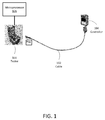
- FIG. 1 shows an example fluid monitoring controller tester system, in accordance with an embodiment.
- a portable tester 100 includes one or more electrical connectors that can be connected to a cable 102, which in turn connects the tester 100 to a fluid monitoring controller 104.
- the tester can be connected to, or include, a microprocessor 106 to automate the tester functions.
- the tester 100 also includes an enclosure that, when used in conjunction with other components of the tester 100, meets or exceeds various safety ratings and standards for operation in explosive environments.
- the ignition level of a gas vapor is dependent upon several factors. These factors include, for example, ignition (arcing or sparking), temperature, oxygen concentration, barometric pressure and humidity. Every chemical has a different volatility, as described in NFPA 325.
- the gas ignition levels of most chemicals can be represented by the ignition levels of four chemical gasses including Group A (Acetylene), Group B (Hydrogen), Group C (Ethylene), and Group D (Propane). Group A is the most volatile and Group D is the least.
- the tester 100 is designed to be used in areas that are represented by Group C, Ethylene gas.
- the ignition point of Ethylene, at 15 Volts DC, can be as much as 5 Amps.
- the tester 100 is designed to receive no more than 250 milliamps at 15 Volts to eliminate heat that can cause an ignition.
- the tester includes voltage and current limiting circuitry that limits the voltage to 15 Vdc and current to 250 mA.
- the tester 100 When the tester 100 is connected to the controller 104, the tester 100 simulates various features, functions and signals of a fuel tanker trailer, including simulating fluid overfill sensors (e.g., two-wire and five-wire configurations) and various truck (e.g., T.I.M. and ground) functions. Such functions and signals are compatible with the operation of the fluid monitoring controller 104.
- the tester 100 has the capability to simulate various different types of fuel tanker trailers without the need for adapters to accommodate different connectors (e.g., J1, J2 and J3 which are described further below), and allows for connection to, and diagnostic testing of, various types of fluid monitoring controllers without the need to connect the controller to an actual trailer or actual sensors.
- the tester 100 includes a control panel (see, e.g., Figure 2 ) that is configured to enable an operator to select the simulated functions and to simulate the output signals of the fuel overfill sensors in the fuel tanker trailer. By selecting these functions and signals, the operator can verify that the fluid monitoring controller 104 is functioning correctly. For example, by simulating a fluid overfill condition in one of the trailer compartments, the operator can verify that the controller 104 generates a "NO PERMIT" condition (e.g., permission to load is denied, or fuel loading is otherwise prevented).
- a control panel see, e.g., Figure 2
- the operator can verify that the fluid monitoring controller 104 is functioning correctly. For example, by simulating a fluid overfill condition in one of the trailer compartments, the operator can verify that the controller 104 generates a "NO PERMIT" condition (e.g., permission to load is denied, or fuel loading is otherwise prevented).
- FIG 2 shows an example control panel 200 of a fluid monitoring controller tester system, in accordance with an embodiment.
- the control panel 200 may, for example, be implemented in the tester 100 of Figure 1 .
- the control panel 200 includes a blue 5-Wire Optical connector (J1), a black 5-Wire Optical connector (J2), a green 2-Wire Optical or Thermistor connector (J3), and a ground ball socket.
- the control panel further includes several selector switches electrically coupled to one or more of the connectors, including a DIODE/OPEN/RES switch for ground testing; a SHORT/TIM Out/TIM In switch for simulating grounding shorts and enabling T.I.M.
- switches may include relays, which may be controlled by a microprocessor, or dry contacts. In some embodiments, the switches may be bypassed and their respective functions implemented by a microprocessor. Table 1 provides an additional description of the functions of each of the switches of the control panel 200.
- Table 1 Tester Control Panel Switches SWITCH STATE FUNCTION DESCRIPTION DIODE Ground testing Up - Connects through diode OPEN Mid - No/Open ground RES Down - Resistive ground SHORT Simulates power signal short & open Up - Supply ground to signal connection TIM Out Enables T.I.M. Mid - T.I.M. disconnected TIM In Down-T.LM.
- SENSOR Simulates 5-Wire sensor diagnostic line including number of sensors Sets the number of 5-Wire sensors to be indicated on the diagnostic line
- 5-WIRE OPTIC Simulates Wet, Dry or Short on 5-Wire sensors Up - Simulates all Dry sensors Mid - Simulates Wet sensor Down - Simulates shorted sensor Switches 1, 2, 3, 4 Sensors 1, 2, 3, 4 Up - 2-Wire Optic in Heated Thermistors Mid - Open/No sensor Down - Heated Thermistor in Switches 5, 6, 7, 8 Sensors 5, 6, 7, 8 Up - 2-Wire Optic in Non-heated Thermistors Mid - Open/No sensor Down - Non-heated Thermistor in
- the tester 100 includes one or more network connections that support wired or wireless communication with external networks (e.g., IP based networks such as LAN's and the like) using, for example, a WI-FI connection, a BLUETOOTH connection, or a ZIGBEE connection.
- external networks e.g., IP based networks such as LAN's and the like
- the tester includes hardware and software that implements a network connection over which the tester communicates with wireless sensors in the fuel tanker trailer.
- the tester includes hardware and software that implements a network connection over which the tester communicates with a public network, such as the Internet.
- An example method of using the tester 100 includes the following:
- FIG. 3 shows an example methodology for ground testing of a fluid monitoring controller using a fluid monitoring controller tester system, in accordance with an embodiment.
- the ground testing switch 300 of the control panel 200 has three positions or states. The upper position connects the Ground Ball to Ground through a Diode (also referred to as a diode ground), which should illuminate a Permit indicator on the controller 104, with a Diode Ground. The center position disconnects the Ground Ball entirely, which should illuminate a NO-PERMIT GND indicator on the controller 104. The Bottom position connects the Ground Ball to ground through a resistor (e.g., 1000 Ohm) (also referred to as a resistive ground), which should illuminate a PERMIT with a resistive ground indicator.
- Figure 3 shows the expected Rack Response to each of the various possible switch settings on the tester, in accordance with an embodiment.
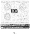
- FIG. 4 shows an example methodology for T.I.M. testing of a fluid monitoring controller using a fluid monitoring controller tester system, in accordance with an embodiment.
- the T.I.M. switch 400 of the control panel 200 has three positions or states. The upper position (spring returned, momentary connection) disconnects the T.I.M. module and provides a shorted path from a signal connector (e.g., Pin 9) to Ground. In the momentary upper SHORT position, the NO-PERMIT GND indicator on the controller 104 should be illuminated. In the center position, the T.I.M. is disconnected, and the NO-PERMIT Idle indicator on the controller 104 should be illuminated. In the bottom position, the T.I.M. is connected and the PERMIT indicator will illuminate on the controller 104.
- Figure 4 shows the expected Rack Response to each of the various possible switch settings on the tester, in accordance with an embodiment.
- FIG. 5 shows an example methodology for 2-Wire Optical sensor testing of a fluid monitoring controller using a fluid monitoring controller tester system, in accordance with an embodiment.
- the states of switches 1 through 8 replicate the functions of eight 2-Wire Optical sensors in the fuel tanker trailer.
- the PERMIT indicator should illuminate on the controller 104.
- any of the eight switches are moved to the CENTER position, simulating a WET condition, the NO-PERMIT indicator for the corresponding sensor should illuminate on the controller 104.
- Figure 5 shows the expected Rack Response to each of the various possible switch settings on the tester, in accordance with an embodiment.
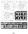
- Figure 6 shows an example methodology for thermistor sensor testing of a fluid monitoring controller using a fluid monitoring controller tester system, in accordance with an embodiment.
- switches 1 through 8 are used to simulate Thermistor sensing, setting all switches to the DOWN position simulates a DRY condition for all sensors, and therefore the PERMIT indicator should illuminate on the controller 104.
- the NO-PERMIT indicator for the corresponding sensor should illuminate on the controller 104.
- switches 1-4 simulate heated thermistors
- switches 5-8 simulate non-heated thermistors, although it will be appreciated that the switches can be configured in any number of different ways.
- Figure 6 shows the expected Rack Response to each of the various possible switch settings on the tester, in accordance with an embodiment.
- FIG. 7 shows an example methodology for 5-Wire Optical sensor testing of a fluid monitoring controller using a fluid monitoring controller tester system, in accordance with an embodiment.
- the 5-Wire Optical toggle switch and the Sensor rotary switch 700 provide several sensor simulation functions.
- the Optic toggle switch is in the DRY (UP) position, the PERMIT indicator should illuminate on the controller 104 regardless of the position of the Sensor rotary switch.
- the Optic toggle switch is in the SHORT (DOWN) position, a shorted sensor is simulated and the NO-PERMIT indicator should illuminate on the controller 104 regardless of the position of the Sensor rotary switch.
- FIG. 8 is a chart showing various testing configurations of the tester, in accordance with an embodiment.
- Figure 9 is a schematic diagram of an example electronic circuit that can be implemented in a fluid monitoring controller tester system, in accordance with an embodiment.
- the circuit shown in Figure 9 may be implemented in the tester 100 of Figure 1 by coupling portions of the circuit to at least one of the electrical connectors of the tester 100 and to at least one of the selector switches of the tester 100.
- the circuit can be configured to simulate a truck identification code based on the selected state of one or more of the selector switches of the tester 100, or to simulate a short circuit based on the selected state of one or more of the selector switches of the tester 100.
Landscapes
- Physics & Mathematics (AREA)
- Fluid Mechanics (AREA)
- General Physics & Mathematics (AREA)
- Testing Or Calibration Of Command Recording Devices (AREA)
- Arrangements For Transmission Of Measured Signals (AREA)
Abstract
Description
- This disclosure relates to portable testing equipment for fluid monitoring equipment.
- A fuel terminal is an industrial facility that stores oil or petrochemical products and from which these products are transported to end users or further storage facilities. A fuel terminal typically has storage tankage, either above ground or underground, and gantries that support the transfer of products from the tankage into fuel tanker trailers or other vehicles. A loading rack is a mechanism for delivering fuel from fuel terminal tankage into a fuel tanker trailer or other means of transfer outside of the fuel terminal.
- Fuel tanker trailers carry fuel in multiple compartments that are generally filled from the bottom. For safety reasons, fluid overfill sensors are placed in each compartment of the trailer to detect potential fluid overfills and provide a signal indicative of an overfill fluid level in a given compartment. Additionally, the trailer is electrically grounded during the filling process to safely dissipate hazardous static electrical charges that could ignite flammable fluids and vapors. During the filling process, the signals provided by the fluid overfill sensors are monitored by a fluid monitoring controller to identify imminent fluid overfills and to prevent their occurrence by causing the loading rack to stop the filling process. The fluid monitoring controller may be an on-board controller integrated with the fuel tanker trailer or a controller integrated with the loading rack. Also, the ground signal is monitored to ensure that the trailer is properly grounded. The fluid monitoring controller should be tested periodically to verify proper operation.
- A presently preferred embodiment of the invention comprises a portable tester of fluid monitoring controllers as defined in
Claim 1. Preferred features of this tester are set out independent claims 2 to 7. Another presently preferred embodiment of the invention comprises a system comprising: a fluid monitoring controller; and a portable tester according to any ofClaims 1 to 7. Preferred features of this system are set out independent claims 9 to 15. - The accompanying drawings are not intended to be drawn to scale. In the drawings, each identical or nearly identical component that is illustrated in various figures is represented by a like numeral. For purposes of clarity, not every component may be labeled in every drawing. In the drawings:
-
Figure 1 shows an example fluid monitoring controller tester system, in accordance with an embodiment of the present disclosure. -
Figure 2 shows an example control panel of a fluid monitoring controller tester system, in accordance with an embodiment of the present disclosure. -
Figure 3 shows an example methodology for ground testing of a fluid monitoring controller using a fluid monitoring controller tester system, in accordance with an embodiment. -
Figure 4 shows an example methodology for T.I.M. (Truck Identification Module) testing of a fluid monitoring controller using a fluid monitoring controller tester system, in accordance with an embodiment. -
Figure 5 shows an example methodology for 2-Wire Optical sensor testing of a fluid monitoring controller using a fluid monitoring controller tester system, in accordance with an embodiment. -
Figure 6 shows an example methodology for thermistor sensor testing of a fluid monitoring controller using a fluid monitoring controller tester system, in accordance with an embodiment. -
Figure 7 shows an example methodology for 5-Wire Optical sensor testing of a fluid monitoring controller using a fluid monitoring controller tester system, in accordance with an embodiment. -
Figure 8 is a chart showing various testing configurations of a fluid monitoring controller tester system, in accordance with an embodiment. -
Figure 9 is a schematic diagram of an example electronic circuit that can be implemented in a fluid monitoring controller tester system, in accordance with an embodiment. - Each of the following U.S. Patents is incorporated in this disclosure by reference in its entirety:
5,365,420 ,5,438,323 ,5,485,401 ,5,507,326 ,5,771,178 ,5,966,311 ,5,986,597 ,7,838,859 ,8,565,966 , and8,731,725 . In addition, the standard BS EN 13922:2011, published September 2011, is hereby incorporated herein by reference in its entirety and describes the specifications for the sensors for the fluid monitoring interface to the sensors according to at least one embodiment. - Portable testing equipment for testing fluid monitoring equipment is disclosed. In some embodiments, the fluid monitoring equipment includes a fluid monitoring controller. As discussed above, a fuel terminal loading rack or fuel tanker trailer includes a fluid monitoring controller for managing the filling process of a fuel tanker trailer. Among other functions, the fluid monitoring controller monitors signals from sensors included in the compartments of the trailer and only permits the transfer of fuel to the trailer compartments when normative conditions are detected. When, for example, a fluid overfill fault or other contingent condition is detected, the fluid monitoring controller automatically stops the fuel transfer, and prevents further transfer of the fuel at least until the fluid overfill fault or other contingent condition is rectified. Testing of the fluid monitoring controller should be performed under controlled conditions to ensure that the controller is operating properly.
- To this end, and in accordance with an embodiment, a portable fluid monitoring controller tester system for fluid monitoring equipment includes a control panel, electrical interfaces, and associated circuitry for simulating the fluid overfill sensors and other features of a trailer. In at least one embodiment, the tester is a self-contained device that meets or exceeds various safety standards applicable to operating in an explosive environment. The tester may be powered, at least partially, by the fluid monitoring controller to which it is connected or from another power source, such as a battery. The tester has intrinsically safe outputs, and is configured to simulate different types of sensor systems found in fuel tanker trailers, including 2-Wire Optical, 5-Wire Optical, and Thermistor sensors. The tester is further configured to simulate ground circuits and the truck identification module (T.I.M.) of the fuel tanker trailer. The tester includes an enclosure that is impact and temperature resilient, and provides protection against windblown dust, rain and splashing water. The system meets or exceeds various standards for operation in explosive environments.
- The electrical interfaces include cable connectors (sockets) that allow the tester to simulate one or more different types of fuel tanker trailer interfaces that can be used in conjunction with a fluid monitoring controller. For example, the tester may include a blue 5-Wire Optical connector, a black 5-Wire Optical connector, a green 2-Wire Optical or Thermistor connector, a ground connector, or any combination of the ground and sensor connectors. The control panel includes several switches for controlling the circuitry that simulates the fluid overfill sensors and other equipment of a fuel tanker trailer. For example, the switches may be selected to simulate wet or dry conditions for each fluid overfill sensor, or to simulate the presence of a short circuit. A wet condition occurs when fluid is detected at the fluid overfill sensor. A dry condition occurs when fluid is not detected at the fluid overfill sensor. The switches may also be selected to simulate an electrical ground or ground fault signal from the fuel tanker trailer, and to simulate reading a T.I.M. serial number from the fuel tanker trailer. In some embodiments, the actions of the switches are automated and controlled via a microprocessor. The microprocessor may be configured to analyze and compare monitoring signals, timing and voltage to a standard. The microprocessor may be configured to compile the analyzed signals, timing and voltage for a certification report, and transmit the analyzed signals, timing and voltage to a distinct system via a network connection.
- In some embodiments, the fluid monitoring controller tester system is designed and configured to meet or exceed one or more of the following safety approvals in at least the United States and Canada: Class I,
Division 1, Group CD, T5,Type 4 or Class I, Zone 0, AEx ia IIB T5, IP54 with intrinsically safe outputs to the EN 13922 connectors, with entity parameters Ui = 15V, Ii = 260mA, Pi = 1.1 W, Ci = 1.25µF, Li = 0, Um= 15 Vdc, and ambient temperature for all ratings Ta ≤ 0°C to +60°C. In some embodiments, the fluid monitoring controller tester system is designed and configured to meet or exceed one or more of the following European safety protocols: 1) Directive 99/92/EC (also known as 'ATEX 137' or the 'ATEX Workplace Directive') on minimum requirements for improving the health and safety protection of workers potentially at risk from explosive atmospheres; and 2) Directive 94/9/EC (also known as 'ATEX 95' or 'the ATEX Equipment Directive') on the approximation of the laws of Members States concerning equipment and protective systems intended for use in potentially explosive atmospheres. An ATEX-approved material, as disclosed herein, includes any material as provided by any ATEX directive that is static dissipative and not containing chrome or other metals that could spark. -
Figure 1 shows an example fluid monitoring controller tester system, in accordance with an embodiment. Aportable tester 100 includes one or more electrical connectors that can be connected to acable 102, which in turn connects thetester 100 to afluid monitoring controller 104. In some embodiments, the tester can be connected to, or include, amicroprocessor 106 to automate the tester functions. Thetester 100 also includes an enclosure that, when used in conjunction with other components of thetester 100, meets or exceeds various safety ratings and standards for operation in explosive environments. The ignition level of a gas vapor is dependent upon several factors. These factors include, for example, ignition (arcing or sparking), temperature, oxygen concentration, barometric pressure and humidity. Every chemical has a different volatility, as described in NFPA 325. The gas ignition levels of most chemicals can be represented by the ignition levels of four chemical gasses including Group A (Acetylene), Group B (Hydrogen), Group C (Ethylene), and Group D (Propane). Group A is the most volatile and Group D is the least. In some embodiments, thetester 100 is designed to be used in areas that are represented by Group C, Ethylene gas. The ignition point of Ethylene, at 15 Volts DC, can be as much as 5 Amps. However, thetester 100 is designed to receive no more than 250 milliamps at 15 Volts to eliminate heat that can cause an ignition. To this end, in some embodiments, the tester includes voltage and current limiting circuitry that limits the voltage to 15 Vdc and current to 250 mA. - When the
tester 100 is connected to thecontroller 104, thetester 100 simulates various features, functions and signals of a fuel tanker trailer, including simulating fluid overfill sensors (e.g., two-wire and five-wire configurations) and various truck (e.g., T.I.M. and ground) functions. Such functions and signals are compatible with the operation of thefluid monitoring controller 104. Thetester 100 has the capability to simulate various different types of fuel tanker trailers without the need for adapters to accommodate different connectors (e.g., J1, J2 and J3 which are described further below), and allows for connection to, and diagnostic testing of, various types of fluid monitoring controllers without the need to connect the controller to an actual trailer or actual sensors. Thetester 100 includes a control panel (see, e.g.,Figure 2 ) that is configured to enable an operator to select the simulated functions and to simulate the output signals of the fuel overfill sensors in the fuel tanker trailer. By selecting these functions and signals, the operator can verify that thefluid monitoring controller 104 is functioning correctly. For example, by simulating a fluid overfill condition in one of the trailer compartments, the operator can verify that thecontroller 104 generates a "NO PERMIT" condition (e.g., permission to load is denied, or fuel loading is otherwise prevented). -
Figure 2 shows anexample control panel 200 of a fluid monitoring controller tester system, in accordance with an embodiment. Thecontrol panel 200 may, for example, be implemented in thetester 100 ofFigure 1 . Thecontrol panel 200 includes a blue 5-Wire Optical connector (J1), a black 5-Wire Optical connector (J2), a green 2-Wire Optical or Thermistor connector (J3), and a ground ball socket. The control panel further includes several selector switches electrically coupled to one or more of the connectors, including a DIODE/OPEN/RES switch for ground testing; a SHORT/TIM Out/TIM In switch for simulating grounding shorts and enabling T.I.M. functions; a SENSOR switch for selecting the number of 5-Wire sensors indicated on the diagnostic line; a 5-Wire Optic switch for simulating wet, dry, or short conditions on 5-Wire sensors; switches 1, 2, 3, 4 for selecting the simulation of one of the 2-Wireoptical sensors optical sensors control panel 200.Table 1 - Tester Control Panel Switches SWITCH STATE FUNCTION DESCRIPTION DIODE Ground testing Up - Connects through diode OPEN Mid - No/Open ground RES Down - Resistive ground SHORT Simulates power signal short & open Up - Supply ground to signal connection TIM Out Enables T.I.M. Mid - T.I.M. disconnected TIM In Down-T.LM. enabled SENSOR Simulates 5-Wire sensor diagnostic line including number of sensors Sets the number of 5-Wire sensors to be indicated on the diagnostic line 5-WIRE OPTIC Simulates Wet, Dry or Short on 5-Wire sensors Up - Simulates all Dry sensors Mid - Simulates Wet sensor Down - Simulates shorted sensor Switches 1, 2, 3, 4 Sensors Up - 2-Wire Optic in Heated Thermistors Mid - Open/No sensor Down - Heated Thermistor in Switches Sensors Up - 2-Wire Optic in Non-heated Thermistors Mid - Open/No sensor Down - Non-heated Thermistor in - In some embodiments, the
tester 100 includes one or more network connections that support wired or wireless communication with external networks (e.g., IP based networks such as LAN's and the like) using, for example, a WI-FI connection, a BLUETOOTH connection, or a ZIGBEE connection. In at least one embodiment, the tester includes hardware and software that implements a network connection over which the tester communicates with wireless sensors in the fuel tanker trailer. In another embodiment, the tester includes hardware and software that implements a network connection over which the tester communicates with a public network, such as the Internet. - An example method of using the
tester 100, in accordance with an embodiment, includes the following: - 1. Set state of switches of
tester 100 for desired simulation conditions. - 2. Connect the
fluid monitoring controller 104 viacable 102 to J1, J2 or J3 oftester 100. - 3. Simulate a fault by toggling the appropriate switches of
tester 100. - 4. Disconnect the
fluid monitoring controller 104 from thetester 100. -
Figure 3 shows an example methodology for ground testing of a fluid monitoring controller using a fluid monitoring controller tester system, in accordance with an embodiment. Theground testing switch 300 of thecontrol panel 200 has three positions or states. The upper position connects the Ground Ball to Ground through a Diode (also referred to as a diode ground), which should illuminate a Permit indicator on thecontroller 104, with a Diode Ground. The center position disconnects the Ground Ball entirely, which should illuminate a NO-PERMIT GND indicator on thecontroller 104. The Bottom position connects the Ground Ball to ground through a resistor (e.g., 1000 Ohm) (also referred to as a resistive ground), which should illuminate a PERMIT with a resistive ground indicator.Figure 3 shows the expected Rack Response to each of the various possible switch settings on the tester, in accordance with an embodiment. -
Figure 4 shows an example methodology for T.I.M. testing of a fluid monitoring controller using a fluid monitoring controller tester system, in accordance with an embodiment. The T.I.M. switch 400 of thecontrol panel 200 has three positions or states. The upper position (spring returned, momentary connection) disconnects the T.I.M. module and provides a shorted path from a signal connector (e.g., Pin 9) to Ground. In the momentary upper SHORT position, the NO-PERMIT GND indicator on thecontroller 104 should be illuminated. In the center position, the T.I.M. is disconnected, and the NO-PERMIT Idle indicator on thecontroller 104 should be illuminated. In the bottom position, the T.I.M. is connected and the PERMIT indicator will illuminate on thecontroller 104.Figure 4 shows the expected Rack Response to each of the various possible switch settings on the tester, in accordance with an embodiment. -
Figure 5 shows an example methodology for 2-Wire Optical sensor testing of a fluid monitoring controller using a fluid monitoring controller tester system, in accordance with an embodiment. For 2-Wire Optical sensor testing, the states ofswitches 1 through 8 replicate the functions of eight 2-Wire Optical sensors in the fuel tanker trailer. When all eight switches are UP, all sensors are simulated as reporting DRY, and therefore the PERMIT indicator should illuminate on thecontroller 104. When any of the eight switches are moved to the CENTER position, simulating a WET condition, the NO-PERMIT indicator for the corresponding sensor should illuminate on thecontroller 104.Figure 5 shows the expected Rack Response to each of the various possible switch settings on the tester, in accordance with an embodiment. -
Figure 6 shows an example methodology for thermistor sensor testing of a fluid monitoring controller using a fluid monitoring controller tester system, in accordance with an embodiment. When switches 1 through 8 are used to simulate Thermistor sensing, setting all switches to the DOWN position simulates a DRY condition for all sensors, and therefore the PERMIT indicator should illuminate on thecontroller 104. When any of the eight switches are moved to the CENTER position, which simulates a WET condition, the NO-PERMIT indicator for the corresponding sensor should illuminate on thecontroller 104. In general, switches 1-4 simulate heated thermistors, and switches 5-8 simulate non-heated thermistors, although it will be appreciated that the switches can be configured in any number of different ways.Figure 6 shows the expected Rack Response to each of the various possible switch settings on the tester, in accordance with an embodiment. -
Figure 7 shows an example methodology for 5-Wire Optical sensor testing of a fluid monitoring controller using a fluid monitoring controller tester system, in accordance with an embodiment. For 5-Wire Optical sensor testing, the 5-Wire Optical toggle switch and theSensor rotary switch 700 provide several sensor simulation functions. When the Optic toggle switch is in the DRY (UP) position, the PERMIT indicator should illuminate on thecontroller 104 regardless of the position of the Sensor rotary switch. When the Optic toggle switch is in the SHORT (DOWN) position, a shorted sensor is simulated and the NO-PERMIT indicator should illuminate on thecontroller 104 regardless of the position of the Sensor rotary switch. When the Optic toggle switch is in the WET (CENTER) position, the Sensor rotary switch can be used to simulate which of the several sensors is indicating a WET condition. Note that eachposition # 1 through #12 simulates that the corresponding sensor is in a WET condition.Figure 8 is a chart showing various testing configurations of the tester, in accordance with an embodiment. -
Figure 9 is a schematic diagram of an example electronic circuit that can be implemented in a fluid monitoring controller tester system, in accordance with an embodiment. For example, the circuit shown inFigure 9 may be implemented in thetester 100 ofFigure 1 by coupling portions of the circuit to at least one of the electrical connectors of thetester 100 and to at least one of the selector switches of thetester 100. In some embodiments, the circuit can be configured to simulate a truck identification code based on the selected state of one or more of the selector switches of thetester 100, or to simulate a short circuit based on the selected state of one or more of the selector switches of thetester 100. - The foregoing description and drawings of various embodiments are presented by way of example only. These examples are not intended to be exhaustive or to limit the invention to the precise forms disclosed. Alterations, modifications, and variations will be apparent in light of this disclosure and are intended to be within the scope of the invention as set forth in the claims.
- It should also be noted that whilst the accompanying claims set out particular combinations of features described herein, the scope of the present invention is not limited to the particular combinations hereafter claimed, but instead extends to encompass any combination of features herein disclosed.
Claims (15)
- A portable tester of fluid monitoring controllers, comprising:an electrical connector configured to be removably connected to a cable;a plurality of selector switches electrically coupled to the electrical connector; andan electronic circuit coupled to the electrical connector and the selector switches, the electronic circuit configured to simulate, via the electrical connector, an output signal of a fuel tanker trailer fluid overfill sensor based on a selected state of the selector switches.
- The tester of claim 1, wherein the output signal represents a wet fluid overfill sensor condition while the selector switches are in a first state, and a dry fluid overfill sensor condition while the selector switches are in a second state that is different than the first state.
- The tester of claim 1 or 2, further comprising an enclosure that is water resistant, impact resistant, and temperature resistant and includes ATEX-approved material.
- The tester of any preceding claim, wherein the tester is configured to be electrically coupled, in place of a fuel tanker trailer, to a fluid monitoring controller, such that signals output via the electrical connector to the fuel terminal fluid monitoring controller simulate signals output by one or more fuel tanker trailer fluid overfill sensors.
- The tester of any preceding claim, wherein the output signal represents a simulated output of an optical fluid overfill sensor or a simulated output of a thermistor.
- The tester of any preceding claim, wherein the electronic circuit is further configured to simulate, via the electrical connector, one or more of the following: (i) a truck identification code based on the selected state of the selector switches; (ii) a short circuit based on the selected state of the selector switches using one of a resistive ground and a diode ground; and (iii) an output signal of at least one of a 2-wire fuel tanker trailer fluid overfill sensor and a 5-wire fuel tanker trailer fluid overfill sensor.
- The tester of any preceding claim, further including circuitry configured to limit voltage within the tester to approximately 15 Vdc or less and current within the tester to approximately 250 mA or less, wherein the circuitry does not include a capacitive element.
- A system comprising: a fluid monitoring controller; and a portable tester according to any of Claims 1 to 7, the tester configured to be electrically connectable to the controller via the cable.
- The system of claim 8, further comprising the cable of claim 1 for electrically connecting the controller to the tester.
- The system of claim 8 or 9, wherein the controller is configured to prevent a fuel transfer via a fuel terminal loading rack while the selector switches are in a first state, and further configured to permit the fuel transfer while the selector switches are in a second state that is different than the first state.
- The system of claim 10, wherein the first state represents a simulated fluid overfill fault or other contingent condition of a fuel tanker trailer, and wherein the second state represents a simulated normative condition of the fuel tanker trailer.
- The system of any of claims 8 to 11, wherein the selector switches are controlled by a microprocessor.
- The system of claim 12, wherein the microprocessor is configured to analyze and compare monitoring signals, timing and voltage to a standard.
- The system of claim 13, wherein the microprocessor is configured to be capable of doing one or more of: (i) compiling the analyzed signals, timing and voltage for a certification report; and (ii) transmitting the analyzed signals, timing and voltage to a system distinct from the system via a network connection.
- The system of claim 14, wherein the network connection includes at least one of a wired connection and a wireless connection, said wireless connection optionally including at least one of a WI-FI connection, a BLUETOOTH connection, and a ZIGBEE connection.
Applications Claiming Priority (1)
| Application Number | Priority Date | Filing Date | Title |
|---|---|---|---|
| US201562169829P | 2015-06-02 | 2015-06-02 |
Publications (2)
| Publication Number | Publication Date |
|---|---|
| EP3101397A1 true EP3101397A1 (en) | 2016-12-07 |
| EP3101397B1 EP3101397B1 (en) | 2023-08-16 |
Family
ID=56117468
Family Applications (1)
| Application Number | Title | Priority Date | Filing Date |
|---|---|---|---|
| EP16020211.5A Active EP3101397B1 (en) | 2015-06-02 | 2016-06-02 | Tester for fluid monitors |
Country Status (3)
| Country | Link |
|---|---|
| US (1) | US10260930B2 (en) |
| EP (1) | EP3101397B1 (en) |
| ES (1) | ES2959238T3 (en) |
Cited By (2)
| Publication number | Priority date | Publication date | Assignee | Title |
|---|---|---|---|---|
| CN108021735A (en) * | 2017-11-07 | 2018-05-11 | 上海科梁信息工程股份有限公司 | Analogy method, host computer, real-time simulation machine and the battery analog system of battery |
| CN110160595A (en) * | 2019-06-19 | 2019-08-23 | 天津科电石化科技发展有限公司 | Liquid level acquisition system based on ZIGBEE Radio Transmission Technology |
Families Citing this family (3)
| Publication number | Priority date | Publication date | Assignee | Title |
|---|---|---|---|---|
| DE102015122284A1 (en) * | 2015-12-18 | 2017-06-22 | Endress + Hauser Gmbh + Co. Kg | Electronic unit with diagnostic function |
| US11901706B2 (en) * | 2020-11-16 | 2024-02-13 | Infinite Energy Construction, Inc. | Operator-safe electrical system enclosure |
| DE102020134061A1 (en) * | 2020-12-17 | 2022-06-23 | Endress+Hauser Flowtec Ag | Radio frequency based field device |
Citations (5)
| Publication number | Priority date | Publication date | Assignee | Title |
|---|---|---|---|---|
| DE2645668A1 (en) * | 1976-10-09 | 1978-04-13 | Daimler Benz Ag | Plug-in test unit for liquid pump controls - has switched resistors to simulate different level probe states |
| GB2277317A (en) * | 1993-04-20 | 1994-10-26 | Loanhead Limited | "A test apparatus for a vehicle fuel dispensing system" |
| DE102004054018A1 (en) * | 2004-11-05 | 2006-05-11 | E.L.B. Füllstandsgeräte Bundschuh GmbH & Co. | Inspection device for overflow protection has selective activatable simulation circuit coupled with functioning element of sensor arrangement and with activation arrangement for its selective operation |
| US20120245792A1 (en) * | 2011-03-23 | 2012-09-27 | Langlais Kenneth L | Portable truck tester |
| WO2015032361A1 (en) * | 2013-09-09 | 2015-03-12 | 北京长吉加油设备有限公司 | Handheld fuel distributor control device with current-limiting battery pack |
Family Cites Families (9)
| Publication number | Priority date | Publication date | Assignee | Title |
|---|---|---|---|---|
| US5438323A (en) | 1993-06-14 | 1995-08-01 | Scully Signal Company | Fail safe fluid level detection circuit |
| US5485401A (en) | 1993-06-14 | 1996-01-16 | Scully Signal Company | Method and apparatus for testing overfill protection devices |
| US5365420A (en) | 1993-06-14 | 1994-11-15 | Scully Signal Company | High efficiency intrinsically safe power supply |
| US5507326A (en) | 1994-08-05 | 1996-04-16 | Scully Signal Company | Fluid overfill protection and product identification system |
| US5771178A (en) | 1995-06-12 | 1998-06-23 | Scully Signal Company | Fail-safe fluid transfer controller |
| US6927958B2 (en) * | 2002-01-07 | 2005-08-09 | Simmonds Precision Products, Inc. | Active transient suppression apparatus for potentially explosive environments |
| EP2242708B1 (en) * | 2007-11-29 | 2012-06-06 | Airbus Operations GmbH | Test equipment for testing an additional center tank (act) system of an aircraft |
| US7838859B2 (en) | 2008-09-29 | 2010-11-23 | Scully Signal Company | Fluid overfill probe with thermal stress prevention |
| US8731725B2 (en) | 2009-01-16 | 2014-05-20 | Scully Signal Company | Truck compartment verification system with alternate truck ID |
-
2016
- 2016-06-02 ES ES16020211T patent/ES2959238T3/en active Active
- 2016-06-02 US US15/171,368 patent/US10260930B2/en active Active
- 2016-06-02 EP EP16020211.5A patent/EP3101397B1/en active Active
Patent Citations (6)
| Publication number | Priority date | Publication date | Assignee | Title |
|---|---|---|---|---|
| DE2645668A1 (en) * | 1976-10-09 | 1978-04-13 | Daimler Benz Ag | Plug-in test unit for liquid pump controls - has switched resistors to simulate different level probe states |
| GB2277317A (en) * | 1993-04-20 | 1994-10-26 | Loanhead Limited | "A test apparatus for a vehicle fuel dispensing system" |
| DE102004054018A1 (en) * | 2004-11-05 | 2006-05-11 | E.L.B. Füllstandsgeräte Bundschuh GmbH & Co. | Inspection device for overflow protection has selective activatable simulation circuit coupled with functioning element of sensor arrangement and with activation arrangement for its selective operation |
| US20120245792A1 (en) * | 2011-03-23 | 2012-09-27 | Langlais Kenneth L | Portable truck tester |
| WO2015032361A1 (en) * | 2013-09-09 | 2015-03-12 | 北京长吉加油设备有限公司 | Handheld fuel distributor control device with current-limiting battery pack |
| EP3045424A1 (en) * | 2013-09-09 | 2016-07-20 | Gilbarco China Co., Ltd. | Handheld fuel distributor control device with current-limiting battery pack |
Cited By (3)
| Publication number | Priority date | Publication date | Assignee | Title |
|---|---|---|---|---|
| CN108021735A (en) * | 2017-11-07 | 2018-05-11 | 上海科梁信息工程股份有限公司 | Analogy method, host computer, real-time simulation machine and the battery analog system of battery |
| CN108021735B (en) * | 2017-11-07 | 2021-06-11 | 上海科梁信息工程股份有限公司 | Battery simulation method, upper computer, real-time simulator and battery simulation system |
| CN110160595A (en) * | 2019-06-19 | 2019-08-23 | 天津科电石化科技发展有限公司 | Liquid level acquisition system based on ZIGBEE Radio Transmission Technology |
Also Published As
| Publication number | Publication date |
|---|---|
| US10260930B2 (en) | 2019-04-16 |
| EP3101397B1 (en) | 2023-08-16 |
| ES2959238T3 (en) | 2024-02-22 |
| US20160356638A1 (en) | 2016-12-08 |
Similar Documents
| Publication | Publication Date | Title |
|---|---|---|
| EP3101397B1 (en) | Tester for fluid monitors | |
| JP6684577B2 (en) | Automatic data bus wire integrity verification device | |
| US10094866B2 (en) | Portable multi-function cable tester | |
| US9759783B2 (en) | Modular testing of a power supply | |
| CA2835934C (en) | Intrinsically safe serviceable transmitter apparatus and method | |
| US8476913B2 (en) | Improvements relating to the testing of an earth connection | |
| US10761129B2 (en) | Electrical power supply panel with increased safety through monitoring and control | |
| KR101108015B1 (en) | Distribution Line Maintaining Apparatus | |
| US20190049508A1 (en) | PORTABLE MULTl-FUNCTION CABLE TESTER | |
| JP2018032389A (en) | Portable field maintenance tool with bus for powering and communicating with field device | |
| EP2215487A1 (en) | Tester for testing signal lines of a flight control system for a ths motor of an aircraft | |
| JP4930105B2 (en) | Test plug test equipment | |
| JP4930106B2 (en) | Electrical signal measuring device | |
| CN106291081B (en) | Far field electric testing system and method | |
| CA2523596A1 (en) | Power supply of a measuring device | |
| US20220158422A1 (en) | Operator-safe electrical system enclosure | |
| US20160003896A1 (en) | Wireless remote power equipment test system and method of using same | |
| US20120319707A1 (en) | Self-monitoring power supply cord and operating equipment | |
| Roman | Introduction to IEC 60335—Household and similar electrical appliances—Safety | |
| US20170227612A1 (en) | Power Supply Arrangement | |
| CA2985646C (en) | Method and system for performing diagnostics and monitoring a dc subsystem | |
| CN104062616A (en) | Direct-current earthing and alternating current-directing current series simulation device | |
| Analyser | Operation and Service Manual | |
| ECNEDIF et al. | Model 2100 6 1/2-Digit Resolution Digital Multimeter | |
| Clark | ELECTRICAL SAFETY (HIPOT) TESTER FUNCTIONS AND APPLICATION. |
Legal Events
| Date | Code | Title | Description |
|---|---|---|---|
| PUAI | Public reference made under article 153(3) epc to a published international application that has entered the european phase |
Free format text: ORIGINAL CODE: 0009012 |
|
| STAA | Information on the status of an ep patent application or granted ep patent |
Free format text: STATUS: THE APPLICATION HAS BEEN PUBLISHED |
|
| AK | Designated contracting states |
Kind code of ref document: A1 Designated state(s): AL AT BE BG CH CY CZ DE DK EE ES FI FR GB GR HR HU IE IS IT LI LT LU LV MC MK MT NL NO PL PT RO RS SE SI SK SM TR |
|
| AX | Request for extension of the european patent |
Extension state: BA ME |
|
| STAA | Information on the status of an ep patent application or granted ep patent |
Free format text: STATUS: REQUEST FOR EXAMINATION WAS MADE |
|
| 17P | Request for examination filed |
Effective date: 20170927 |
|
| RBV | Designated contracting states (corrected) |
Designated state(s): AL AT BE BG CH CY CZ DE DK EE ES FI FR GB GR HR HU IE IS IT LI LT LU LV MC MK MT NL NO PL PT RO RS SE SI SK SM TR |
|
| STAA | Information on the status of an ep patent application or granted ep patent |
Free format text: STATUS: EXAMINATION IS IN PROGRESS |
|
| 17Q | First examination report despatched |
Effective date: 20210602 |
|
| STAA | Information on the status of an ep patent application or granted ep patent |
Free format text: STATUS: EXAMINATION IS IN PROGRESS |
|
| REG | Reference to a national code |
Ref country code: DE Ref legal event code: R079 Ref document number: 602016081912 Country of ref document: DE Free format text: PREVIOUS MAIN CLASS: G01F0025000000 Ipc: G01F0025200000 Ref country code: DE Ref legal event code: R079 Free format text: PREVIOUS MAIN CLASS: G01F0025000000 Ipc: G01F0025200000 |
|
| GRAP | Despatch of communication of intention to grant a patent |
Free format text: ORIGINAL CODE: EPIDOSNIGR1 |
|
| STAA | Information on the status of an ep patent application or granted ep patent |
Free format text: STATUS: GRANT OF PATENT IS INTENDED |
|
| RIC1 | Information provided on ipc code assigned before grant |
Ipc: G01F 23/292 20060101ALN20230314BHEP Ipc: G01F 23/24 20060101ALN20230314BHEP Ipc: B67D 7/32 20100101ALN20230314BHEP Ipc: B67D 7/08 20100101ALI20230314BHEP Ipc: B67D 7/04 20100101ALI20230314BHEP Ipc: G01F 25/20 20220101AFI20230314BHEP |
|
| INTG | Intention to grant announced |
Effective date: 20230331 |
|
| GRAS | Grant fee paid |
Free format text: ORIGINAL CODE: EPIDOSNIGR3 |
|
| P01 | Opt-out of the competence of the unified patent court (upc) registered |
Effective date: 20230530 |
|
| GRAA | (expected) grant |
Free format text: ORIGINAL CODE: 0009210 |
|
| STAA | Information on the status of an ep patent application or granted ep patent |
Free format text: STATUS: THE PATENT HAS BEEN GRANTED |
|
| AK | Designated contracting states |
Kind code of ref document: B1 Designated state(s): AL AT BE BG CH CY CZ DE DK EE ES FI FR GB GR HR HU IE IS IT LI LT LU LV MC MK MT NL NO PL PT RO RS SE SI SK SM TR |
|
| REG | Reference to a national code |
Ref country code: GB Ref legal event code: FG4D |
|
| REG | Reference to a national code |
Ref country code: CH Ref legal event code: EP Ref country code: DE Ref legal event code: R096 Ref document number: 602016081912 Country of ref document: DE |
|
| REG | Reference to a national code |
Ref country code: IE Ref legal event code: FG4D |
|
| REG | Reference to a national code |
Ref country code: LT Ref legal event code: MG9D |
|
| REG | Reference to a national code |
Ref country code: NL Ref legal event code: MP Effective date: 20230816 |
|
| REG | Reference to a national code |
Ref country code: AT Ref legal event code: MK05 Ref document number: 1600475 Country of ref document: AT Kind code of ref document: T Effective date: 20230816 |
|
| PG25 | Lapsed in a contracting state [announced via postgrant information from national office to epo] |
Ref country code: GR Free format text: LAPSE BECAUSE OF FAILURE TO SUBMIT A TRANSLATION OF THE DESCRIPTION OR TO PAY THE FEE WITHIN THE PRESCRIBED TIME-LIMIT Effective date: 20231117 |
|
| PG25 | Lapsed in a contracting state [announced via postgrant information from national office to epo] |
Ref country code: IS Free format text: LAPSE BECAUSE OF FAILURE TO SUBMIT A TRANSLATION OF THE DESCRIPTION OR TO PAY THE FEE WITHIN THE PRESCRIBED TIME-LIMIT Effective date: 20231216 |
|
| PG25 | Lapsed in a contracting state [announced via postgrant information from national office to epo] |
Ref country code: SE Free format text: LAPSE BECAUSE OF FAILURE TO SUBMIT A TRANSLATION OF THE DESCRIPTION OR TO PAY THE FEE WITHIN THE PRESCRIBED TIME-LIMIT Effective date: 20230816 Ref country code: RS Free format text: LAPSE BECAUSE OF FAILURE TO SUBMIT A TRANSLATION OF THE DESCRIPTION OR TO PAY THE FEE WITHIN THE PRESCRIBED TIME-LIMIT Effective date: 20230816 Ref country code: PT Free format text: LAPSE BECAUSE OF FAILURE TO SUBMIT A TRANSLATION OF THE DESCRIPTION OR TO PAY THE FEE WITHIN THE PRESCRIBED TIME-LIMIT Effective date: 20231218 Ref country code: NO Free format text: LAPSE BECAUSE OF FAILURE TO SUBMIT A TRANSLATION OF THE DESCRIPTION OR TO PAY THE FEE WITHIN THE PRESCRIBED TIME-LIMIT Effective date: 20231116 Ref country code: NL Free format text: LAPSE BECAUSE OF FAILURE TO SUBMIT A TRANSLATION OF THE DESCRIPTION OR TO PAY THE FEE WITHIN THE PRESCRIBED TIME-LIMIT Effective date: 20230816 Ref country code: LV Free format text: LAPSE BECAUSE OF FAILURE TO SUBMIT A TRANSLATION OF THE DESCRIPTION OR TO PAY THE FEE WITHIN THE PRESCRIBED TIME-LIMIT Effective date: 20230816 Ref country code: LT Free format text: LAPSE BECAUSE OF FAILURE TO SUBMIT A TRANSLATION OF THE DESCRIPTION OR TO PAY THE FEE WITHIN THE PRESCRIBED TIME-LIMIT Effective date: 20230816 Ref country code: IS Free format text: LAPSE BECAUSE OF FAILURE TO SUBMIT A TRANSLATION OF THE DESCRIPTION OR TO PAY THE FEE WITHIN THE PRESCRIBED TIME-LIMIT Effective date: 20231216 Ref country code: HR Free format text: LAPSE BECAUSE OF FAILURE TO SUBMIT A TRANSLATION OF THE DESCRIPTION OR TO PAY THE FEE WITHIN THE PRESCRIBED TIME-LIMIT Effective date: 20230816 Ref country code: GR Free format text: LAPSE BECAUSE OF FAILURE TO SUBMIT A TRANSLATION OF THE DESCRIPTION OR TO PAY THE FEE WITHIN THE PRESCRIBED TIME-LIMIT Effective date: 20231117 Ref country code: FI Free format text: LAPSE BECAUSE OF FAILURE TO SUBMIT A TRANSLATION OF THE DESCRIPTION OR TO PAY THE FEE WITHIN THE PRESCRIBED TIME-LIMIT Effective date: 20230816 Ref country code: AT Free format text: LAPSE BECAUSE OF FAILURE TO SUBMIT A TRANSLATION OF THE DESCRIPTION OR TO PAY THE FEE WITHIN THE PRESCRIBED TIME-LIMIT Effective date: 20230816 |
|
| REG | Reference to a national code |
Ref country code: ES Ref legal event code: FG2A Ref document number: 2959238 Country of ref document: ES Kind code of ref document: T3 Effective date: 20240222 |
|
| PG25 | Lapsed in a contracting state [announced via postgrant information from national office to epo] |
Ref country code: PL Free format text: LAPSE BECAUSE OF FAILURE TO SUBMIT A TRANSLATION OF THE DESCRIPTION OR TO PAY THE FEE WITHIN THE PRESCRIBED TIME-LIMIT Effective date: 20230816 |
|
| PG25 | Lapsed in a contracting state [announced via postgrant information from national office to epo] |
Ref country code: SM Free format text: LAPSE BECAUSE OF FAILURE TO SUBMIT A TRANSLATION OF THE DESCRIPTION OR TO PAY THE FEE WITHIN THE PRESCRIBED TIME-LIMIT Effective date: 20230816 Ref country code: RO Free format text: LAPSE BECAUSE OF FAILURE TO SUBMIT A TRANSLATION OF THE DESCRIPTION OR TO PAY THE FEE WITHIN THE PRESCRIBED TIME-LIMIT Effective date: 20230816 Ref country code: EE Free format text: LAPSE BECAUSE OF FAILURE TO SUBMIT A TRANSLATION OF THE DESCRIPTION OR TO PAY THE FEE WITHIN THE PRESCRIBED TIME-LIMIT Effective date: 20230816 Ref country code: DK Free format text: LAPSE BECAUSE OF FAILURE TO SUBMIT A TRANSLATION OF THE DESCRIPTION OR TO PAY THE FEE WITHIN THE PRESCRIBED TIME-LIMIT Effective date: 20230816 Ref country code: CZ Free format text: LAPSE BECAUSE OF FAILURE TO SUBMIT A TRANSLATION OF THE DESCRIPTION OR TO PAY THE FEE WITHIN THE PRESCRIBED TIME-LIMIT Effective date: 20230816 Ref country code: SK Free format text: LAPSE BECAUSE OF FAILURE TO SUBMIT A TRANSLATION OF THE DESCRIPTION OR TO PAY THE FEE WITHIN THE PRESCRIBED TIME-LIMIT Effective date: 20230816 |
|
| REG | Reference to a national code |
Ref country code: DE Ref legal event code: R097 Ref document number: 602016081912 Country of ref document: DE |
|
| PLBE | No opposition filed within time limit |
Free format text: ORIGINAL CODE: 0009261 |
|
| STAA | Information on the status of an ep patent application or granted ep patent |
Free format text: STATUS: NO OPPOSITION FILED WITHIN TIME LIMIT |
|
| PGFP | Annual fee paid to national office [announced via postgrant information from national office to epo] |
Ref country code: GB Payment date: 20240627 Year of fee payment: 9 |
|
| 26N | No opposition filed |
Effective date: 20240517 |
|
| PG25 | Lapsed in a contracting state [announced via postgrant information from national office to epo] |
Ref country code: IT Free format text: LAPSE BECAUSE OF FAILURE TO SUBMIT A TRANSLATION OF THE DESCRIPTION OR TO PAY THE FEE WITHIN THE PRESCRIBED TIME-LIMIT Effective date: 20230816 Ref country code: SI Free format text: LAPSE BECAUSE OF FAILURE TO SUBMIT A TRANSLATION OF THE DESCRIPTION OR TO PAY THE FEE WITHIN THE PRESCRIBED TIME-LIMIT Effective date: 20230816 |
|
| PGFP | Annual fee paid to national office [announced via postgrant information from national office to epo] |
Ref country code: FR Payment date: 20240625 Year of fee payment: 9 |
|
| PGFP | Annual fee paid to national office [announced via postgrant information from national office to epo] |
Ref country code: BE Payment date: 20240627 Year of fee payment: 9 |