EP3101396B1 - Verkaufskühlmöbel mit einem sensor zur detektion eines verstopften ablaufs - Google Patents
Verkaufskühlmöbel mit einem sensor zur detektion eines verstopften ablaufs Download PDFInfo
- Publication number
- EP3101396B1 EP3101396B1 EP16172598.1A EP16172598A EP3101396B1 EP 3101396 B1 EP3101396 B1 EP 3101396B1 EP 16172598 A EP16172598 A EP 16172598A EP 3101396 B1 EP3101396 B1 EP 3101396B1
- Authority
- EP
- European Patent Office
- Prior art keywords
- drain
- sensor
- inductance
- fluid
- level
- Prior art date
- Legal status (The legal status is an assumption and is not a legal conclusion. Google has not performed a legal analysis and makes no representation as to the accuracy of the status listed.)
- Active
Links
Images


Classifications
-
- G—PHYSICS
- G01—MEASURING; TESTING
- G01F—MEASURING VOLUME, VOLUME FLOW, MASS FLOW OR LIQUID LEVEL; METERING BY VOLUME
- G01F23/00—Indicating or measuring liquid level or level of fluent solid material, e.g. indicating in terms of volume or indicating by means of an alarm
- G01F23/22—Indicating or measuring liquid level or level of fluent solid material, e.g. indicating in terms of volume or indicating by means of an alarm by measuring physical variables, other than linear dimensions, pressure or weight, dependent on the level to be measured, e.g. by difference of heat transfer of steam or water
- G01F23/26—Indicating or measuring liquid level or level of fluent solid material, e.g. indicating in terms of volume or indicating by means of an alarm by measuring physical variables, other than linear dimensions, pressure or weight, dependent on the level to be measured, e.g. by difference of heat transfer of steam or water by measuring variations of capacity or inductance of capacitors or inductors arising from the presence of liquid or fluent solid material in the electric or electromagnetic fields
-
- A—HUMAN NECESSITIES
- A47—FURNITURE; DOMESTIC ARTICLES OR APPLIANCES; COFFEE MILLS; SPICE MILLS; SUCTION CLEANERS IN GENERAL
- A47F—SPECIAL FURNITURE, FITTINGS, OR ACCESSORIES FOR SHOPS, STOREHOUSES, BARS, RESTAURANTS OR THE LIKE; PAYING COUNTERS
- A47F3/00—Show cases or show cabinets
- A47F3/04—Show cases or show cabinets air-conditioned, refrigerated
- A47F3/0478—Control or safety arrangements
-
- G—PHYSICS
- G01—MEASURING; TESTING
- G01F—MEASURING VOLUME, VOLUME FLOW, MASS FLOW OR LIQUID LEVEL; METERING BY VOLUME
- G01F23/00—Indicating or measuring liquid level or level of fluent solid material, e.g. indicating in terms of volume or indicating by means of an alarm
- G01F23/80—Arrangements for signal processing
- G01F23/802—Particular electronic circuits for digital processing equipment
-
- G—PHYSICS
- G08—SIGNALLING
- G08B—SIGNALLING SYSTEMS, e.g. PERSONAL CALLING SYSTEMS; ORDER TELEGRAPHS; ALARM SYSTEMS
- G08B21/00—Alarms responsive to a single specified undesired or abnormal condition and not otherwise provided for
- G08B21/18—Status alarms
- G08B21/182—Level alarms, e.g. alarms responsive to variables exceeding a threshold
-
- A—HUMAN NECESSITIES
- A47—FURNITURE; DOMESTIC ARTICLES OR APPLIANCES; COFFEE MILLS; SPICE MILLS; SUCTION CLEANERS IN GENERAL
- A47F—SPECIAL FURNITURE, FITTINGS, OR ACCESSORIES FOR SHOPS, STOREHOUSES, BARS, RESTAURANTS OR THE LIKE; PAYING COUNTERS
- A47F3/00—Show cases or show cabinets
- A47F3/04—Show cases or show cabinets air-conditioned, refrigerated
- A47F3/0439—Cases or cabinets of the open type
-
- E—FIXED CONSTRUCTIONS
- E03—WATER SUPPLY; SEWERAGE
- E03C—DOMESTIC PLUMBING INSTALLATIONS FOR FRESH WATER OR WASTE WATER; SINKS
- E03C1/00—Domestic plumbing installations for fresh water or waste water; Sinks
- E03C1/12—Plumbing installations for waste water; Basins or fountains connected thereto; Sinks
- E03C1/24—Overflow devices for basins or baths
- E03C2001/2406—Overflow alarm devices
-
- F—MECHANICAL ENGINEERING; LIGHTING; HEATING; WEAPONS; BLASTING
- F25—REFRIGERATION OR COOLING; COMBINED HEATING AND REFRIGERATION SYSTEMS; HEAT PUMP SYSTEMS; MANUFACTURE OR STORAGE OF ICE; LIQUEFACTION SOLIDIFICATION OF GASES
- F25D—REFRIGERATORS; COLD ROOMS; ICE-BOXES; COOLING OR FREEZING APPARATUS NOT OTHERWISE PROVIDED FOR
- F25D2700/00—Means for sensing or measuring; Sensors therefor
Definitions
- the present invention generally relates to a refrigerated display case which has a drain and a system for detecting a substance in the drain, and more particularly a sensor that detects a clogged drain using inductive frequency characterization.
- Refrigerated display cases include a control system to maintain the temperature of a space relative to a set point by activating a refrigeration unit to cool the space.
- the refrigeration unit supplies sub-cooled refrigerant to an evaporator coil, which cools warm air from the space that is circulated across the evaporator coil.
- the warm air contacts the colder surface of the evaporator coil (e.g., in air conditioning systems) or when in a defrost mode (e.g., in refrigeration systems), water can accumulate on the evaporator.
- the water condensation runs down the sides of the evaporator coil and collects in a display case tub.
- the display case tub has a drain fitting and drain line attached thereto, which allows the water to drain from the display case tub.
- Blockage in the drain line can occur due to food or liquid spills into the display case, as well as due to algae, fungus and/or bacterial growth, all of which may form particles that create restrictions in the drain line.
- Such restriction can cause water to back up into the display case tub.
- the display case tub When the display case tub is full of water, the water will overflow out of the tub and into the surrounding area, potentially creating a safety hazard and/or water damage to the surrounding area.
- the water in the display case tub may also freeze and traditional level sensing devices fail to accurately operate in these scenarios.
- US-A-5729990 discloses a temperature dependent resistor as a liquid sensor which detects the presence of liquid at a level above a cooling chamber drip tray provided with a drain channel.
- the temperature dependent resistor is mounted external to the liquid sensor because it must be in direct contact with liquid. Electric power is provided to heat the resistor. The relative temperature change before and after the resistor is heated provides a clear indication as to whether the liquid sensor is surrounded by water or ice or by air.
- US-A-2008/143345 discloses a monitoring device which is deployed in the urea tank of a selective catalytic reduction system of a vehicle.
- the monitoring device includes a radio frequency signal generator and a resonant circuit having an inductor and a capacitor. The output signal from the inductor and capacitor is dependent on the level of the urea solution in the tank.
- US-A-2011/058931 discloses a pump system which includes a sensor for the level of a lubricating oil for the pump. Plates in a housing for the oil form a capacitor when the housing contains oil. The plate arrangement provides a signal indicative of the level of oil in the housing.
- US-A-2011/259953 discloses a system for monitoring the level of a liquid food product in a food dispenser.
- a sensor circuit includes a coil, a resistor and a capacitor. The impedance of the sensor circuit depends on the level of liquid in a container for the product.
- a combined fluid level sensor and/or drain cover (hereinafter referred to as a drain sensor), which may be for detecting a clog within or around a drain, may utilize a sensor (e.g., a solid state sensor, an inductive sensor, a sensor having a non-contact sensing element, or the like) having an inductance that varies based on the presence of substances in the area of the drain, and a support member to which the sensor is mounted.
- the support member may form a protective shroud around a sensing portion so as to protect it from contact with debris/substances that may fall into the display case tub.
- the invention therefore provides a refrigerated display case which has a drain and a system for detecting a substance in the drain, as defined in claim 1.
- a drain sensor which is a used in the display case includes a support member having a cage configuration.
- the sensor is attached to the support member and arranged within the cage, and the entire assembly is placed in, over or around the drain that is to be monitored.
- the cage prevents large substances, such as food particles, labels, wire ties and the like that may be unintentionally deposited in a refrigerated display case, from contacting the sensor and providing false readings.
- a fluid, moisture or substance level around the drain is determined. For example, as fluid level rises the inductance of the sensor also rises, and this increase (or decrease) can be measured and correlated to the level of the substance. If the detected level rises above a prescribed level, an alarm can be generated to notify the appropriate personnel.
- the sensing element may include an inductor forming an impedance transformer of the surrounding fluid, moisture or substance.
- the measurement circuitry may be configured to supply an oscillating current to the inductor and to calculate an inductance of the impedance transformer based on a resonant frequency of the impedance transformer.
- the measurement circuitry may be configured to determine the level based on a predefined mapping between a plurality of different inductances and a plurality of different levels of a fluid, moisture or substance corresponding to the different inductances.
- the cage may include an open end.
- the cage may include a closed end.
- the drain sensor may include a base member, which may be removably attached to the open end of the cage.
- the closed end may be formed by a metallic disk member, which may be attached to a first end of the cage.
- the open end may be formed by an annular member, which may be attached to a second end of the cage opposite the first end.
- the sensing element may be fixedly attached to the disk member and may extend toward the open end.
- the cage may comprise a screen which may have a bar or cross-hatch configuration.
- the support member may comprise a plurality of fastener receivers, which may be for fixing the support member to a support surface.
- the drain sensor may include at least one of a wired communication device or wireless communication device, which may be communicatively coupled to the sensing element and may be operative to communicate measurements made by the sensing element to a device, which may be remote from the drain sensor.
- An inductance of the sensing element may correspond to a level of fluid, moisture or solid substance present in the cage.
- the inductance measurement may increase as fluid, moisture or substance level increases.
- the sensing element may comprise a two-dimensional coil.
- the sensing element may comprise a three-dimensional coil.
- the controller may be configured to at least one of: generate an alarm when the measured fluid level exceeds a prescribed level, or provide an indication of the presence of fluid; or provide an indication of a rate of fluid rise in the drain.
- the mapping may be configured such that increasing inductance corresponds to increasing fluid, moisture or substance level.
- the invention also provides a method for determining a fluid, moisture or solid substance level in a drain in a refrigerated display case, as defined in claim 11.
- the method may include determining the fluid level when a temperature in the area being monitored is less than 0°C (32°F).
- an alarm may be generated to inform the appropriate personnel of a possible clogged drain if the level of the substance relative to the drain exceeds a prescribed level.
- an output may be provided showing the actual level and/or a rate of increase in the level of the substance.
- a drain sensor having a body with a first annular end, and a second disk-shape end.
- the drain sensor further includes a sensor disposed on the second end and extending toward the first end.
- the sensor is configured to provide an inductance that changes in response to contact with or presence of a substance, such as water, ice or like substance.
- the sensor is arranged to detect a level of the substance relative to the opening in the first end.
- the drain sensor is preferably configured to detect a liquid level indicative of a clogged drain line when the sensor provides an output indicative of contact (or near contact) with fluid.
- the sensor may be employed in a circuit including the sensor, the circuit configured to detect when the sensor provides an output indicative of fluid contact.
- the drain sensor is employed with a controller, where the controller is in communication with the output of the circuit and/or sensor, and is configured to communicate a signal indicative of preferably a clogged drain line based on the output of the sensor, as explained below.
- the controller may include a mapping, such as a look-up table or the like, stored in memory, the mapping including a plurality of different inductances of the sensor along with a corresponding fluid, moisture or substance level for each inductance of the sensor. Based on a measured inductance of the sensor, the controller can retrieve the corresponding fluid, moisture or substance level from memory.
- the drain sensor includes a primary circuit formed by an inductor having a fixed inductance in parallel with a capacitor having a known capacitance.
- An oscillator supplies an oscillating AC current to the primary circuit and generates a magnetic field in the surrounding material that produces eddy currents in the surrounding material.
- the impedance in the surrounding material is transformed to the primary circuit, and this impedance can be measured to determine the presence of fluid, moisture and/or a substance, e.g., by mapping different measured inductances to different fluid levels, moisture levels, etc.
- a refrigerated display case 10 for conditioning a space 12 is shown.
- refrigerated display cases provide a refrigerated environment in which food products may be displayed without being exposed to warm temperatures.
- the refrigerated display case 10 includes a refrigeration unit 14 having an evaporator coil 16, a compressor 18, condenser coil 20 and an expansion valve 22 for providing cooling operation. While the refrigeration unit is shown as being part of the display case, portions of the refrigeration unit may be located remote from the display case.
- the refrigerated display case 10 may be controllably operated by a device 24 (e.g., a thermostat, controller or the like) operatively coupled to the space 12 and the refrigeration unit 14.
- a device 24 e.g., a thermostat, controller or the like
- warm air from the space 12 is circulated across the evaporator coil 16, in which a two-phase refrigerant removes heat from the air.
- a drain sensor 30 including a sensor and associated circuitry for measuring an inductance is arranged relative to the drain 32 to detect a clog in the drain 32.
- liquid water, food juices, spilled substances, cleaning agents, etc.
- this liquid may collect during a defrost cycle and/or during a wash down cycle, and this liquid is also collected and routed to the drain 32.
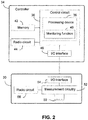
- Fig. 2 shows a exemplary controller 34 and drain sensor 30. While the controller 34 and drain sensor 30 are shown as separate devices, part or all of the controller 34 may be integrated with the drain sensor 30 to form a single integrated unit.
- the controller 34 includes a control circuit 36 that is responsible for overall operation of the controller 34.
- the control circuit 36 includes a processing device 38 (e.g., a processor) that executes various applications, such as a monitoring function 40 for monitoring a status of the drain 32 as described in greater detail below.
- the monitoring function 40 may be implemented in the form of logical instructions that are executed by the processing device 38.
- the processing device 38 of the control circuit 36 may be a central processing unit (CPU), microcontroller, microprocessor, or the like.
- the processing device 38 executes code stored in a memory (not shown) within the control circuit 36 and/or in a separate memory, such as a memory 42, in order to carry out operation of the controller 34.
- the memory 42 may be, for example, one or more of a buffer, a flash memory, a hard drive, a removable media, a volatile memory, a non-volatile memory, a random access memory (RAM), or other suitable device.
- the memory 42 includes a non-volatile memory for long term data storage and a volatile memory that functions as system memory for the control circuit 36.
- the memory 42 may exchange data with the control circuit 36 over a data bus. Accompanying control lines and an address bus between the memory 42 and the control circuit 36 also may be present.
- the memory 42 is considered a non-transitory computer readable medium.
- the controller 34 may include communications circuitry that enables the controller 34 to establish various wireless communication connections.
- the communications circuitry includes a radio circuit 44.
- the radio circuit 44 includes one or more radio frequency transceivers and an antenna assembly (or assemblies).
- the controller 34 may be capable of communicating using more than one standard (e.g., WiFi or Bluetooth interface). Therefore, the radio circuit 44 represents each radio transceiver and antenna needed for the various supported connection types.
- the controller 34 is configured to engage in wireless communications using the radio circuit 44, such as data transfers and the like.
- the drain sensor 30 may include a coil 50 or other inductive sensing device operatively coupled to measurement circuitry 52.
- the coil 50 may be packaged as a two-dimensional package or as a three-dimensional package as described in further detail below with reference to Figs. 4A and 4B .
- the measurement circuitry 52 is configured to measure the inductance of the coil 50. Such measurement may be represented, for example, as digital value or as an analog voltage or current signal that is proportional to the change in measured inductance. Operation of the measurement circuitry 52 is described below.
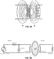
- a classical transformer refers to a two coil system where two coils share a field. Current in the first coil stores energy in the magnetic field, and that energy is "transformed” via the field into the second coil in the form of current.
- Fig. 3A illustrates such configuration, where "A" is the primary coil and "B" is the secondary coil.
- Fig. 3B shows a sensor which has a physical primary coil having a fixed inductance (inductance A), while the secondary coil is formed by the fluid, substance, or moisture.
- the field emitted by the primary coil causes circular currents to form in the fluid, moisture or substance. These current then generate their own inductive load (inductance B). Also present in both coils is resistance (resistance A and resistance B, respectively).
- the primary side circuit i.e., the portion of the circuit to the left of the shared field
- the primary side circuit i.e., the portion of the circuit to the left of the shared field
- the primary side circuit also has a capacitance that is fixed and independent of fluid, moisture or substance level. The more fluid, moisture or substance, the more shared field and thus the more induced inductance.
- Both the capacitance and the inductance of the primary and secondary circuits depend on the oscillation frequency. There exists a single frequency value (the resonant frequency) for which the capacitive load and inductive impedance terms cancel each other out. When this occurs, the power losses on the current arrive at a local minimum.
- the measurement circuitry 52 changes its frequency of oscillation until it finds the resonant frequency. When this occurs, the net impedance can be calculated. This transformed impedance is characteristic of the level of the fluid, moisture or substance. Higher levels engage more magnetic field allowing for more load sharing.
- the drain sensor 30 may include one or more input/output (I/O) interface(s) 54 and a radio circuit 56.
- the I/O interface 54 and radio circuit 56 are similar to the I/O interface 46 and radio circuit 44 of the controller 34. Thus, and for sake of brevity, the description of these devices will not be repeated here.
- the I/O interface 54 and/or radio circuit 56 enable the controller 34 to be communicatively coupled to the measurement circuitry 52 and/or coil 50 to receive data corresponding to an inductance measurement of the coil 50. Based on the inductance measurement of the coil 50, the controller 34 is configured to determine the presence of a substance in the drain and/or a level of the substance.
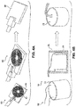
- Figs. 4A and 4B show coil packages that may be used in the drain sensor 30.
- Fig. 4A illustrates a two-dimensional package 60, where conductive traces 62 are formed on a printed circuit board 64, the traces, for example, having a spiral configuration. Other configurations may be employed for the traces depending on the requirements of the specific application. Wires electrically connect the traces 62 to the measurement circuitry 52, thus enabling measurement of inductance.
- the spiral traces 62 and printed circuit board 64 may be placed within a protective housing 66, which may be formed from a plastic or like material. The housing 66 is attached to a support member of the drain sensor 30 as described below with reference to Figs. 5A and 5B .
- Fig. 4B illustrates use of a three-dimensional coil package 70, where a conductive wire is coiled 72 one loop above the other to form a wire stack 74.
- the stack 74 then is placed in a protective housing 76 (e.g., a plastic housing), such as a cylindrical housing, and a potting compound 78 or the like is placed within the housing so as to seal and protect the wire stack 74.
- Wires 80 electrically connect the stack 74 to the measurement circuitry 52.
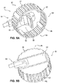
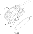
- Figs. 5A and 5B are bottom and top perspective views of a drain sensor 30. While the drain sensor 30 is shown having a cylindrical shape, other shapes may be employed depending on the specific application for the drain sensor. For example, a rectangular shape may be employed when the drain 32 is formed as a narrow channel.
- the drain sensor 30 includes a support member 80 for placement relative to the drain 32.
- the support member 80 is configured to be inserted into the drain 32, and in another embodiment the support member 80 is configured to be placed immediately over the drain 32 and/or near the drain 32.
- the support member 80 defines a cage portion 82 (e.g., a screen with a bar or cross-hatch configuration) preferably having an open end 84 and a closed end 86.
- the closed end 86 may be formed, for example, by a disk member 88 attached to one end of the cage portion 82 (e.g., a first end), and the open end 84 may be formed by an annular member 90 attached to the opposite end (e.g., a second end) of the cage portion.
- the annular member 90 and the disk member 88 may be connected to one another via a plurality of supports 92.
- Figs. 5A and 5B show the supports 92 having a bar-like configuration.
- a plurality of elongated members arranged generally parallel to one another attach the disk member 88 to the annular member 90.
- a spacing between adjacent elongated members is preferably selected to prevent substances having dimensions over a prescribed size from passing between adjacent supports 92.
- additional supports may be arranged perpendicular to the supports 92 and circumferentially around the cage portion 82.
- the supports 92 may be arranged to form a cross-hatch configuration.
- the cage portion 82 forms a cylindrical housing that houses and protects the coil 50.
- the measurement circuitry 52 and radio circuitry 56 may be arranged within the cage portion 82 or external to the cage portion (e.g., on a top surface of the support member 80 - see Fig. 5B ).
- the measurement circuitry 52 is arranged within the cage portion 82 to provide protection from falling substances/spills/leaks that are typically encountered in a refrigerated display case.
- a wire harness 94 which may be located perpendicular to the coil 50, provides signals to and from the controller 34 (e.g., supply voltage to the coil and signal voltage from the coil). Alternatively or additionally, power may be provided to the coil via a power storage device, e.g., a battery or the like).
- the support member 80 may include one or more receiving means 96, such as through holes or the like, for receiving respective fasteners (e.g., a threaded fastener - not shown).
- the receiving means 96 in conjunction with the fasteners enable the support member 80 to be fixedly attached to a support surface of the refrigerated display case 10.
- the drain sensor 30 can be connected to a drain cap of a display case. As the fluid (water or other) level rises in the display case, fluid, moisture and/or substances enter through the exterior openings of the cage portion 82 and, if the drain is clogged, submerges at least part of the coil 50.
- the sensing portion of the drain sensor 30 includes a sensor (coil 50).
- the coil 50 is attached to the support member 80 and arranged within the cage portion 82.
- the coil may be fixedly attached to the disk member 88 and extend toward the open end 84.
- the inductance of the coil 50 varies in the presence of fluid, moisture or substance and by measuring the inductance of the coil a level of the fluid, substance and/or amount of moisture in or near the cage portion 82 can be deduced.
- Fig. 7 shows logical operations 100 to implement a method of monitoring a drain using the drain sensor 30 in accordance with the present invention.
- the exemplary method may be carried out by executing an embodiment of the monitoring function 40, for example.
- the flow chart of Fig. 7 may be thought of as depicting steps of a method carried out by the controller 34 and/or drain sensor 30.
- Fig. 7 shows a specific order of executing functional logic blocks, the order of executing the blocks may be changed relative to the order shown.
- two or more blocks shown in succession may be executed concurrently or with partial concurrence. Certain blocks also may be omitted.
- any number of functions, logical operations, commands, state variables, semaphores or messages may be added to the logical flow for purposes of enhanced utility, accounting, performance, measurement, troubleshooting, and the like.
- the logical flow for the monitoring function 40 may begin at step 102 where the measurement circuitry 52 obtains a measurement of the inductance of coil 50.
- the inductance of coil 50 is affected by the presence of a liquid, such as water, or a solid, e.g., ice, food particles, etc.
- the measured inductance of coil 50 then is communicated to the controller 34 for further processing.
- Such communication may be by way of a wireless communication channel using the radio circuits 44 and 56, or by way of a wired connection using the I/O interfaces 46 and 54 (e.g., a USB or other serial connection).
- the fluid level is calculated. Such calculation is based on the measured inductance of the coil 50. For example, testing has shown that a test (sample) coil has an inductance of about 19.5 ⁇ H when in free space (i.e., no liquid in the immediate vicinity of the coil 50), about 20.9 ⁇ H when about fifty percent of the coil is immersed in water, and about 21.714 ⁇ H when the coil 50 is about seventy-five percent immersed in water. Accordingly, the relationship between inductance of the coil and fluid level is linear and, therefore, the fluid level can be calculated based on the measured inductance of the coil 50 and the known linear relationship.
- the rate of fluid rise may optionally be calculated.
- the change in inductance of the coil 50 over time can be used to calculate the rate at which the liquid level is rising or falling. Such information, for example, may be helpful in determining the severity of the drain clog and/or the success of a defrost cycle.
- the measured level and/or rate may be compared to prescribed threshold levels to determine if further action is required.
- the threshold levels may be user programmable to allow system customization. If at step 110 the measured/calculated level or rate do not exceed respective prescribed threshold levels, the method moves back to step 102 and repeats. However, if measured/calculated level or rate do exceed the respective prescribed thresholds, the method moves to step 112 where an alarm is generated (e.g., an audible and/or visual alarm such as an LED sequence), and then the method moves back to step 102.
- an alarm e.g., an audible and/or visual alarm such as an LED sequence
- the drain sensor 30 does not use any moving parts and therefore is not subjected to mechanical wear. Additionally, because the sensor does not have any dependency on fluid conductivity, the fluid detected by the drain sensor 30 may include other constituents besides water, such as orange juice, coffee, dust, dirt, food juices, etc. Further, the drain sensor 30 can operate even when the liquid freezes (e.g., it can detect ice) and can be configured such that it does not include exposed conductors or the like that may corrode. This is in contrast to commercially available condensate drain sensors, which have an operating limit of 0°C (32°F) or above and/or have exposed conductors.
- the cage design eliminates false alarms due to the sensor being covered and protected by the cage portion 82.
- the drain sensor 30 along with its control logic may preferably have the ability to predict clogged drains based on rate of fill and rate of decay of the historical data, and can categorize alarms as having different levels of urgency (e.g., High, Medium, Low) based on rate of fill, rate of decay height of fluid sensed and use of historical data.
- levels of urgency e.g., High, Medium, Low
Landscapes
- Physics & Mathematics (AREA)
- Engineering & Computer Science (AREA)
- General Physics & Mathematics (AREA)
- Thermal Sciences (AREA)
- Fluid Mechanics (AREA)
- Signal Processing (AREA)
- Electromagnetism (AREA)
- Power Engineering (AREA)
- Business, Economics & Management (AREA)
- Emergency Management (AREA)
- Investigating Or Analyzing Materials By The Use Of Electric Means (AREA)
Claims (12)
- Eine Kühlvitrine (10) mit einem Ablauf (32) und einem System zum Detektieren einer Substanz in dem Ablauf umfassend:ein Ablaufsensor (30), der relativ zum Ablauf angeordnet ist, um das Flüssigkeits-, Feuchtigkeits- oder Feststoffniveau im Ablauf zu detektieren, und der umfasst:ein Stützelement (80) zum Anordnen relativ zu einem Ablauf, wobei das Stützelement einen Käfig (82) umfasst,ein Messelement (50), das am Stützelement angebracht und innerhalb des Käfigs angeordnet ist, undeine Messschaltung (52), die funktionsmäßig mit dem Messelement gekoppelt ist, wobei die Messschaltung dazu in der Lage ist, eine Induktivitätsmessung des Messelements bereitzustellen, wobei die Induktivität des Messelements proportional zu einem Flüssigkeits-, Feuchtigkeits- oder Feststoffniveau relativ zu dem Messelement ist, undwobei das System fernereine Steuerung (34) umfasst, die kommunizierend mit dem Ablaufsensor (30) verbunden ist, um einer Induktivitätsmessung entsprechende und vom Sensor bereitgestellte Daten zu empfangen, wobei die Steuerung dazu eingerichtet ist, ausgehend von der Induktivitätsmessung des Sensors das Flüssigkeits-, Feuchtigkeits- oder Feststoffniveau im Ablauf zu detektieren.
- Die Vitrine gemäß Anspruch 1, wobei die Steuerung (34) dazu eingerichtet ist, um:einen Alarm zu erzeugen, wenn das gemessene Flüssigkeitsniveau ein vorgeschriebenes Niveau überschreitet, und/ odereinen Hinweis für das Vorhandensein von Flüssigkeit bereitzustellen, und/ odereinen Hinweis für eine Flüssigkeitsanstiegsrate im Ablauf (32) bereitzustellen.
- Die Vitrine gemäß Anspruch 1 oder Anspruch 2, wobei die Steuerung (34) dazu eingerichtet ist, ein Substanzniveau, ausgehend von einer Zuordnung zwischen Induktivität und Substanzniveau, zu bestimmen.
- Die Vitrine gemäß Anspruch 3, wobei die Zuordnung derart eingerichtet ist, dass steigende Induktivität steigendem Substanzniveau entspricht.
- Die Vitrine gemäß einem der Ansprüche 1 bis 4, wobei das Messelement eine Induktorspule (50) umfasst, die einen Impedanzwandler der/ des umgebenden Flüssigkeit, Feuchtigkeit oder Feststoffs bildet, und die Messschaltung (52) dazu eingerichtet ist, der Induktorspule einen Wechselstrom zuzuführen und eine von einer Eigenfrequenz des Impedanzwandlers ausgehende Induktivität des Impedanzwandlers zu berechnen.
- Die Vitrine gemäß Anspruch 5, wobei die Messschaltung (52) dazu eingerichtet ist, um das von einer vordefinierten Zuordnung zwischen einer Vielzahl verschiedener Induktivitäten des Messelements (50) und einer Vielzahl verschiedener Substanzniveaus, die den verschiedenen Induktivitäten entsprechen, ausgehende Niveau zu bestimmen.
- Die Vitrine gemäß einem der Ansprüche 1 bis 6, die zumindest eine drahtgebundene Kommunikationsvorrichtung und eine drahtlose Kommunikationsvorrichtung (44) umfasst, die kommunizierend mit dem Messelement (50) verbunden und dazu in der Lage ist, Induktivitätsmessungen an eine vom Ablaufsensor (30) entfernte Vorrichtung zu kommunizieren.
- Die Vitrine gemäß einem der Ansprüche 1 bis 7, wobei die Induktivität des Messelements (50) einem im Käfig (82) vorhandenen Substanzniveau entspricht.
- Die Vitrine gemäß einem der Ansprüche 1 bis 8, wobei das Messelement eine zweidimensionale Spule (60) umfasst.
- Die Vitrine gemäß einem der Ansprüche 1 bis 8, wobei das Messelement eine dreidimensionale Spule (70) umfasst.
- Ein Verfahren zum Bestimmen eines Flüssigkeits-, Feuchtigkeits- oder Feststoffniveaus in einem Ablauf in einer Kühlvitrine unter Verwendung eines Ablaufsensors, der ein Stützelement zum Anordnen relativ zu einem Ablauf umfasst, wobei das Stützelement einen Käfig, ein Messelement, das am Stützelement angebracht und innerhalb des Käfigs angeordnet ist, und eine Messschaltung, die funktionsmäßig mit dem Messelement gekoppelt ist, wobei die Messschaltung dazu in der Lage ist, eine Induktivitätsmessung des Messelements bereitzustellen, wobei die Induktivität des Messelements proportional zu einem Flüssigkeits-, Feuchtigkeits- oder Feststoffniveau relativ zum Messelement ist, und eine Steuerung umfasst, die kommunikativ mit dem Ablaufsensor gekoppelt ist, um einer Induktivitätsmessung entsprechende und vom Sensor bereitgestellte Daten zu empfangen, wobei die Steuerung dazu eingerichtet ist, ausgehend von der Induktivitätsmessung des Sensors das Flüssigkeits-, Feuchtigkeits- oder Feststoffniveau im Ablauf zu detektieren, wobei das Verfahren umfasst:Anordnen des Ablaufsensors in einem Ablauf der Kühlvitrine, wobei der Ablaufsensor relativ zum Ablauf angeordnet ist, um ein Flüssigkeits-, Feuchtigkeits- oder Feststoffniveau im Ablauf zu detektieren,Zuordnen des Flüssigkeits-, Feuchtigkeits- oder Feststoffniveaus zur Induktivität des Sensors, sodass steigende Induktivität einer Steigerung des Flüssigkeits-, Feuchtigkeits- oder Feststoffniveaus entspricht,Messen einer Induktivität des Sensors, undBestimmen des Flüssigkeits-, Feuchtigkeits- oder Feststoffniveaus ausgehend von der gemessenen Induktivität und der Zuordnung zwischen Flüssigkeits-, Feuchtigkeits- oder Feststoffniveau und Induktivität.
- Das Verfahren gemäß Anspruch 11, das das Bestimmen des Flüssigkeits-, Feuchtigkeits- oder Feststoffniveaus umfasst, wenn die Temperatur im Ablauf kleiner als 0°C (32°F) ist.
Applications Claiming Priority (1)
| Application Number | Priority Date | Filing Date | Title |
|---|---|---|---|
| US201562169754P | 2015-06-02 | 2015-06-02 |
Publications (3)
| Publication Number | Publication Date |
|---|---|
| EP3101396A2 EP3101396A2 (de) | 2016-12-07 |
| EP3101396A3 EP3101396A3 (de) | 2017-01-18 |
| EP3101396B1 true EP3101396B1 (de) | 2018-08-15 |
Family
ID=56611188
Family Applications (1)
| Application Number | Title | Priority Date | Filing Date |
|---|---|---|---|
| EP16172598.1A Active EP3101396B1 (de) | 2015-06-02 | 2016-06-02 | Verkaufskühlmöbel mit einem sensor zur detektion eines verstopften ablaufs |
Country Status (2)
| Country | Link |
|---|---|
| US (1) | US20160356637A1 (de) |
| EP (1) | EP3101396B1 (de) |
Families Citing this family (7)
| Publication number | Priority date | Publication date | Assignee | Title |
|---|---|---|---|---|
| EP3521524A1 (de) | 2018-02-06 | 2019-08-07 | IPee N.V. | Sanitärvorrichtung mit einer sensorschaltung und verwendung davon |
| CN108428533B (zh) * | 2018-04-26 | 2024-10-01 | 核工业理化工程研究院 | 一种安装在印制线路板上的水冷电感模块的安装方法及其应用 |
| CA194480S (en) * | 2019-10-15 | 2022-01-17 | Schweitzer Project S P A | Refrigerator |
| US10995488B1 (en) | 2019-11-20 | 2021-05-04 | Whirlpool Corporation | Servicing assembly for an insulated structure |
| GB2599094B (en) * | 2020-09-21 | 2024-11-20 | Charles Austen Pumps Ltd | A condensate tray assembly |
| CN113418963B (zh) * | 2021-06-22 | 2022-08-16 | 北京工商大学 | 树干冻融阻抗图像实时检测方法与系统 |
| US12264872B2 (en) | 2022-10-24 | 2025-04-01 | Whirlpool Corporation | Insulation panel assembly for a refrigeration unit |
Family Cites Families (9)
| Publication number | Priority date | Publication date | Assignee | Title |
|---|---|---|---|---|
| US4165641A (en) * | 1974-06-17 | 1979-08-28 | P. R. Mallory & Co. Inc. | Liquid level sensing means |
| US4418570A (en) * | 1981-12-08 | 1983-12-06 | Exxon Production Research Co. | Ice thickness inductor probe |
| DE4418313C2 (de) * | 1994-05-26 | 1997-09-25 | Danfoss As | Tauwasserschale für eine Kälteanlage |
| US5965814A (en) * | 1997-10-21 | 1999-10-12 | French; Arnold E. | Freeze/overflow detector with deactivating mechanism |
| US7814787B2 (en) * | 2006-09-20 | 2010-10-19 | Itt Manufacturing Enterprises, Inc. | Combined oil level or condition sensor and sight oil level gage |
| US8482298B2 (en) * | 2006-12-18 | 2013-07-09 | Schrader Electronics Ltd. | Liquid level and composition sensing systems and methods using EMF wave propagation |
| JP6144620B2 (ja) * | 2010-04-08 | 2017-06-07 | アクセス ビジネス グループ インターナショナル リミテッド ライアビリティ カンパニー | POS(pointofsale)誘導性システムと方法 |
| GB2498557A (en) * | 2012-01-19 | 2013-07-24 | Greenskye Solutions Ltd | Means to Detect Frost or Condensate in a Cooled Chamber Such as a Refrigerator. |
| EP2890240A1 (de) * | 2012-08-29 | 2015-07-08 | Yissum Research Development Company of the Hebrew University of Jerusalem Ltd. | System und verfahren zur bestimmung von flüssigkeitseigenschaften |
-
2016
- 2016-06-02 EP EP16172598.1A patent/EP3101396B1/de active Active
- 2016-06-02 US US15/171,038 patent/US20160356637A1/en not_active Abandoned
Non-Patent Citations (1)
| Title |
|---|
| None * |
Also Published As
| Publication number | Publication date |
|---|---|
| EP3101396A2 (de) | 2016-12-07 |
| US20160356637A1 (en) | 2016-12-08 |
| EP3101396A3 (de) | 2017-01-18 |
Similar Documents
| Publication | Publication Date | Title |
|---|---|---|
| EP3101396B1 (de) | Verkaufskühlmöbel mit einem sensor zur detektion eines verstopften ablaufs | |
| US11733106B2 (en) | Sensor, controller and system | |
| US20150059469A1 (en) | Method and apparatus for remotely monitoring liquid food products | |
| KR102633940B1 (ko) | 차량용 액체 저장탱크의 액위 모니터링 장치 및 방법 | |
| WO2005106813A3 (en) | Shelf-life monitoring sensor-transponder system | |
| AU2008247845A1 (en) | Insulated container having a temperature monitoring device | |
| MX2007011596A (es) | Sistema y metodo para supervisar alimentos. | |
| EP2400282B1 (de) | Verfahren und Steuerung von Verfahrensparametern | |
| Athauda et al. | Electromagnetic characterization of a food safe, organic smart material for customizable temperature threshold sensing in cold chain applications | |
| AU2012203454B2 (en) | Apparatus and Method for Detecting a Loose Electrical Connection | |
| US6568263B1 (en) | Liquid level detector and system | |
| EP0680590B1 (de) | Zustandserfassungssystem zur kontrolle von arbeitsflüssigkeiten | |
| CN100504327C (zh) | 具有用来表示影响数据载体的参数变化的指示装置的数据载体 | |
| CN116888468A (zh) | 用信号评估流体质量 | |
| CN116529546B (zh) | 具有用于负荷确定的感测的电器 | |
| US11199435B2 (en) | Device for detecting the fill level of media in containers | |
| EP3062071A1 (de) | Becherhalter und zugehöriges verfahren zur identifizierung der füllstands eines bechers | |
| GB2498557A (en) | Means to Detect Frost or Condensate in a Cooled Chamber Such as a Refrigerator. | |
| JP4647905B2 (ja) | 家庭用電気製品 | |
| Miller et al. | Technical issues with refrigerators | |
| Woodward | Wireless Fluid-Level Sensors for Harsh Environments | |
| HK40015357A (en) | Device for detecting the fill level of media in containers | |
| HK40015357B (en) | Device for detecting the fill level of media in containers |
Legal Events
| Date | Code | Title | Description |
|---|---|---|---|
| PUAI | Public reference made under article 153(3) epc to a published international application that has entered the european phase |
Free format text: ORIGINAL CODE: 0009012 |
|
| STAA | Information on the status of an ep patent application or granted ep patent |
Free format text: STATUS: THE APPLICATION HAS BEEN PUBLISHED |
|
| AK | Designated contracting states |
Kind code of ref document: A2 Designated state(s): AL AT BE BG CH CY CZ DE DK EE ES FI FR GB GR HR HU IE IS IT LI LT LU LV MC MK MT NL NO PL PT RO RS SE SI SK SM TR |
|
| AX | Request for extension of the european patent |
Extension state: BA ME |
|
| PUAL | Search report despatched |
Free format text: ORIGINAL CODE: 0009013 |
|
| AK | Designated contracting states |
Kind code of ref document: A3 Designated state(s): AL AT BE BG CH CY CZ DE DK EE ES FI FR GB GR HR HU IE IS IT LI LT LU LV MC MK MT NL NO PL PT RO RS SE SI SK SM TR |
|
| AX | Request for extension of the european patent |
Extension state: BA ME |
|
| RIC1 | Information provided on ipc code assigned before grant |
Ipc: G01F 23/00 20060101ALI20161212BHEP Ipc: F25D 21/14 20060101ALI20161212BHEP Ipc: G01F 23/26 20060101AFI20161212BHEP Ipc: A47F 3/04 20060101ALI20161212BHEP Ipc: F25D 29/00 20060101ALI20161212BHEP |
|
| STAA | Information on the status of an ep patent application or granted ep patent |
Free format text: STATUS: REQUEST FOR EXAMINATION WAS MADE |
|
| 17P | Request for examination filed |
Effective date: 20170208 |
|
| RBV | Designated contracting states (corrected) |
Designated state(s): AL AT BE BG CH CY CZ DE DK EE ES FI FR GB GR HR HU IE IS IT LI LT LU LV MC MK MT NL NO PL PT RO RS SE SI SK SM TR |
|
| GRAP | Despatch of communication of intention to grant a patent |
Free format text: ORIGINAL CODE: EPIDOSNIGR1 |
|
| STAA | Information on the status of an ep patent application or granted ep patent |
Free format text: STATUS: GRANT OF PATENT IS INTENDED |
|
| INTG | Intention to grant announced |
Effective date: 20180328 |
|
| GRAS | Grant fee paid |
Free format text: ORIGINAL CODE: EPIDOSNIGR3 |
|
| GRAA | (expected) grant |
Free format text: ORIGINAL CODE: 0009210 |
|
| STAA | Information on the status of an ep patent application or granted ep patent |
Free format text: STATUS: THE PATENT HAS BEEN GRANTED |
|
| AK | Designated contracting states |
Kind code of ref document: B1 Designated state(s): AL AT BE BG CH CY CZ DE DK EE ES FI FR GB GR HR HU IE IS IT LI LT LU LV MC MK MT NL NO PL PT RO RS SE SI SK SM TR |
|
| REG | Reference to a national code |
Ref country code: CH Ref legal event code: EP Ref country code: GB Ref legal event code: FG4D Ref country code: AT Ref legal event code: REF Ref document number: 1030324 Country of ref document: AT Kind code of ref document: T Effective date: 20180815 |
|
| REG | Reference to a national code |
Ref country code: IE Ref legal event code: FG4D |
|
| REG | Reference to a national code |
Ref country code: DE Ref legal event code: R096 Ref document number: 602016004693 Country of ref document: DE |
|
| REG | Reference to a national code |
Ref country code: NL Ref legal event code: MP Effective date: 20180815 |
|
| REG | Reference to a national code |
Ref country code: LT Ref legal event code: MG4D |
|
| REG | Reference to a national code |
Ref country code: AT Ref legal event code: MK05 Ref document number: 1030324 Country of ref document: AT Kind code of ref document: T Effective date: 20180815 |
|
| PG25 | Lapsed in a contracting state [announced via postgrant information from national office to epo] |
Ref country code: IS Free format text: LAPSE BECAUSE OF FAILURE TO SUBMIT A TRANSLATION OF THE DESCRIPTION OR TO PAY THE FEE WITHIN THE PRESCRIBED TIME-LIMIT Effective date: 20181215 Ref country code: RS Free format text: LAPSE BECAUSE OF FAILURE TO SUBMIT A TRANSLATION OF THE DESCRIPTION OR TO PAY THE FEE WITHIN THE PRESCRIBED TIME-LIMIT Effective date: 20180815 Ref country code: AT Free format text: LAPSE BECAUSE OF FAILURE TO SUBMIT A TRANSLATION OF THE DESCRIPTION OR TO PAY THE FEE WITHIN THE PRESCRIBED TIME-LIMIT Effective date: 20180815 Ref country code: LT Free format text: LAPSE BECAUSE OF FAILURE TO SUBMIT A TRANSLATION OF THE DESCRIPTION OR TO PAY THE FEE WITHIN THE PRESCRIBED TIME-LIMIT Effective date: 20180815 Ref country code: BG Free format text: LAPSE BECAUSE OF FAILURE TO SUBMIT A TRANSLATION OF THE DESCRIPTION OR TO PAY THE FEE WITHIN THE PRESCRIBED TIME-LIMIT Effective date: 20181115 Ref country code: SE Free format text: LAPSE BECAUSE OF FAILURE TO SUBMIT A TRANSLATION OF THE DESCRIPTION OR TO PAY THE FEE WITHIN THE PRESCRIBED TIME-LIMIT Effective date: 20180815 Ref country code: NL Free format text: LAPSE BECAUSE OF FAILURE TO SUBMIT A TRANSLATION OF THE DESCRIPTION OR TO PAY THE FEE WITHIN THE PRESCRIBED TIME-LIMIT Effective date: 20180815 Ref country code: FI Free format text: LAPSE BECAUSE OF FAILURE TO SUBMIT A TRANSLATION OF THE DESCRIPTION OR TO PAY THE FEE WITHIN THE PRESCRIBED TIME-LIMIT Effective date: 20180815 Ref country code: GR Free format text: LAPSE BECAUSE OF FAILURE TO SUBMIT A TRANSLATION OF THE DESCRIPTION OR TO PAY THE FEE WITHIN THE PRESCRIBED TIME-LIMIT Effective date: 20181116 Ref country code: NO Free format text: LAPSE BECAUSE OF FAILURE TO SUBMIT A TRANSLATION OF THE DESCRIPTION OR TO PAY THE FEE WITHIN THE PRESCRIBED TIME-LIMIT Effective date: 20181115 |
|
| PG25 | Lapsed in a contracting state [announced via postgrant information from national office to epo] |
Ref country code: LV Free format text: LAPSE BECAUSE OF FAILURE TO SUBMIT A TRANSLATION OF THE DESCRIPTION OR TO PAY THE FEE WITHIN THE PRESCRIBED TIME-LIMIT Effective date: 20180815 Ref country code: HR Free format text: LAPSE BECAUSE OF FAILURE TO SUBMIT A TRANSLATION OF THE DESCRIPTION OR TO PAY THE FEE WITHIN THE PRESCRIBED TIME-LIMIT Effective date: 20180815 Ref country code: AL Free format text: LAPSE BECAUSE OF FAILURE TO SUBMIT A TRANSLATION OF THE DESCRIPTION OR TO PAY THE FEE WITHIN THE PRESCRIBED TIME-LIMIT Effective date: 20180815 |
|
| PG25 | Lapsed in a contracting state [announced via postgrant information from national office to epo] |
Ref country code: ES Free format text: LAPSE BECAUSE OF FAILURE TO SUBMIT A TRANSLATION OF THE DESCRIPTION OR TO PAY THE FEE WITHIN THE PRESCRIBED TIME-LIMIT Effective date: 20180815 Ref country code: EE Free format text: LAPSE BECAUSE OF FAILURE TO SUBMIT A TRANSLATION OF THE DESCRIPTION OR TO PAY THE FEE WITHIN THE PRESCRIBED TIME-LIMIT Effective date: 20180815 Ref country code: RO Free format text: LAPSE BECAUSE OF FAILURE TO SUBMIT A TRANSLATION OF THE DESCRIPTION OR TO PAY THE FEE WITHIN THE PRESCRIBED TIME-LIMIT Effective date: 20180815 Ref country code: CZ Free format text: LAPSE BECAUSE OF FAILURE TO SUBMIT A TRANSLATION OF THE DESCRIPTION OR TO PAY THE FEE WITHIN THE PRESCRIBED TIME-LIMIT Effective date: 20180815 Ref country code: PL Free format text: LAPSE BECAUSE OF FAILURE TO SUBMIT A TRANSLATION OF THE DESCRIPTION OR TO PAY THE FEE WITHIN THE PRESCRIBED TIME-LIMIT Effective date: 20180815 |
|
| REG | Reference to a national code |
Ref country code: DE Ref legal event code: R097 Ref document number: 602016004693 Country of ref document: DE |
|
| PG25 | Lapsed in a contracting state [announced via postgrant information from national office to epo] |
Ref country code: SK Free format text: LAPSE BECAUSE OF FAILURE TO SUBMIT A TRANSLATION OF THE DESCRIPTION OR TO PAY THE FEE WITHIN THE PRESCRIBED TIME-LIMIT Effective date: 20180815 Ref country code: DK Free format text: LAPSE BECAUSE OF FAILURE TO SUBMIT A TRANSLATION OF THE DESCRIPTION OR TO PAY THE FEE WITHIN THE PRESCRIBED TIME-LIMIT Effective date: 20180815 Ref country code: SM Free format text: LAPSE BECAUSE OF FAILURE TO SUBMIT A TRANSLATION OF THE DESCRIPTION OR TO PAY THE FEE WITHIN THE PRESCRIBED TIME-LIMIT Effective date: 20180815 |
|
| PLBE | No opposition filed within time limit |
Free format text: ORIGINAL CODE: 0009261 |
|
| STAA | Information on the status of an ep patent application or granted ep patent |
Free format text: STATUS: NO OPPOSITION FILED WITHIN TIME LIMIT |
|
| 26N | No opposition filed |
Effective date: 20190516 |
|
| PG25 | Lapsed in a contracting state [announced via postgrant information from national office to epo] |
Ref country code: SI Free format text: LAPSE BECAUSE OF FAILURE TO SUBMIT A TRANSLATION OF THE DESCRIPTION OR TO PAY THE FEE WITHIN THE PRESCRIBED TIME-LIMIT Effective date: 20180815 |
|
| PG25 | Lapsed in a contracting state [announced via postgrant information from national office to epo] |
Ref country code: MC Free format text: LAPSE BECAUSE OF FAILURE TO SUBMIT A TRANSLATION OF THE DESCRIPTION OR TO PAY THE FEE WITHIN THE PRESCRIBED TIME-LIMIT Effective date: 20180815 |
|
| REG | Reference to a national code |
Ref country code: CH Ref legal event code: PL |
|
| REG | Reference to a national code |
Ref country code: BE Ref legal event code: MM Effective date: 20190630 |
|
| PG25 | Lapsed in a contracting state [announced via postgrant information from national office to epo] |
Ref country code: TR Free format text: LAPSE BECAUSE OF FAILURE TO SUBMIT A TRANSLATION OF THE DESCRIPTION OR TO PAY THE FEE WITHIN THE PRESCRIBED TIME-LIMIT Effective date: 20180815 |
|
| PG25 | Lapsed in a contracting state [announced via postgrant information from national office to epo] |
Ref country code: IE Free format text: LAPSE BECAUSE OF NON-PAYMENT OF DUE FEES Effective date: 20190602 |
|
| PG25 | Lapsed in a contracting state [announced via postgrant information from national office to epo] |
Ref country code: CH Free format text: LAPSE BECAUSE OF NON-PAYMENT OF DUE FEES Effective date: 20190630 Ref country code: LU Free format text: LAPSE BECAUSE OF NON-PAYMENT OF DUE FEES Effective date: 20190602 Ref country code: BE Free format text: LAPSE BECAUSE OF NON-PAYMENT OF DUE FEES Effective date: 20190630 Ref country code: LI Free format text: LAPSE BECAUSE OF NON-PAYMENT OF DUE FEES Effective date: 20190630 |
|
| PG25 | Lapsed in a contracting state [announced via postgrant information from national office to epo] |
Ref country code: PT Free format text: LAPSE BECAUSE OF FAILURE TO SUBMIT A TRANSLATION OF THE DESCRIPTION OR TO PAY THE FEE WITHIN THE PRESCRIBED TIME-LIMIT Effective date: 20181215 |
|
| PG25 | Lapsed in a contracting state [announced via postgrant information from national office to epo] |
Ref country code: CY Free format text: LAPSE BECAUSE OF FAILURE TO SUBMIT A TRANSLATION OF THE DESCRIPTION OR TO PAY THE FEE WITHIN THE PRESCRIBED TIME-LIMIT Effective date: 20180815 |
|
| PG25 | Lapsed in a contracting state [announced via postgrant information from national office to epo] |
Ref country code: MT Free format text: LAPSE BECAUSE OF FAILURE TO SUBMIT A TRANSLATION OF THE DESCRIPTION OR TO PAY THE FEE WITHIN THE PRESCRIBED TIME-LIMIT Effective date: 20180815 Ref country code: HU Free format text: LAPSE BECAUSE OF FAILURE TO SUBMIT A TRANSLATION OF THE DESCRIPTION OR TO PAY THE FEE WITHIN THE PRESCRIBED TIME-LIMIT; INVALID AB INITIO Effective date: 20160602 |
|
| PG25 | Lapsed in a contracting state [announced via postgrant information from national office to epo] |
Ref country code: MK Free format text: LAPSE BECAUSE OF FAILURE TO SUBMIT A TRANSLATION OF THE DESCRIPTION OR TO PAY THE FEE WITHIN THE PRESCRIBED TIME-LIMIT Effective date: 20180815 |
|
| P01 | Opt-out of the competence of the unified patent court (upc) registered |
Effective date: 20230524 |
|
| PGFP | Annual fee paid to national office [announced via postgrant information from national office to epo] |
Ref country code: DE Payment date: 20250627 Year of fee payment: 10 |
|
| PGFP | Annual fee paid to national office [announced via postgrant information from national office to epo] |
Ref country code: GB Payment date: 20250627 Year of fee payment: 10 |
|
| PGFP | Annual fee paid to national office [announced via postgrant information from national office to epo] |
Ref country code: FR Payment date: 20250625 Year of fee payment: 10 |
|
| PGFP | Annual fee paid to national office [announced via postgrant information from national office to epo] |
Ref country code: IT Payment date: 20250619 Year of fee payment: 10 |