EP3101265A1 - Flow rate control valve - Google Patents
Flow rate control valve Download PDFInfo
- Publication number
- EP3101265A1 EP3101265A1 EP15739838.9A EP15739838A EP3101265A1 EP 3101265 A1 EP3101265 A1 EP 3101265A1 EP 15739838 A EP15739838 A EP 15739838A EP 3101265 A1 EP3101265 A1 EP 3101265A1
- Authority
- EP
- European Patent Office
- Prior art keywords
- valve
- rotating shaft
- moving member
- valve body
- valve member
- Prior art date
- Legal status (The legal status is an assumption and is not a legal conclusion. Google has not performed a legal analysis and makes no representation as to the accuracy of the status listed.)
- Withdrawn
Links
Images


Classifications
-
- F—MECHANICAL ENGINEERING; LIGHTING; HEATING; WEAPONS; BLASTING
- F16—ENGINEERING ELEMENTS AND UNITS; GENERAL MEASURES FOR PRODUCING AND MAINTAINING EFFECTIVE FUNCTIONING OF MACHINES OR INSTALLATIONS; THERMAL INSULATION IN GENERAL
- F16K—VALVES; TAPS; COCKS; ACTUATING-FLOATS; DEVICES FOR VENTING OR AERATING
- F16K27/00—Construction of housing; Use of materials therefor
- F16K27/02—Construction of housing; Use of materials therefor of lift valves
-
- F—MECHANICAL ENGINEERING; LIGHTING; HEATING; WEAPONS; BLASTING
- F02—COMBUSTION ENGINES; HOT-GAS OR COMBUSTION-PRODUCT ENGINE PLANTS
- F02M—SUPPLYING COMBUSTION ENGINES IN GENERAL WITH COMBUSTIBLE MIXTURES OR CONSTITUENTS THEREOF
- F02M69/00—Low-pressure fuel-injection apparatus ; Apparatus with both continuous and intermittent injection; Apparatus injecting different types of fuel
- F02M69/30—Low-pressure fuel-injection apparatus ; Apparatus with both continuous and intermittent injection; Apparatus injecting different types of fuel characterised by means for facilitating the starting-up or idling of engines or by means for enriching fuel charge, e.g. below operational temperatures or upon high power demand of engines
- F02M69/32—Low-pressure fuel-injection apparatus ; Apparatus with both continuous and intermittent injection; Apparatus injecting different types of fuel characterised by means for facilitating the starting-up or idling of engines or by means for enriching fuel charge, e.g. below operational temperatures or upon high power demand of engines with an air by-pass around the air throttle valve or with an auxiliary air passage, e.g. with a variably controlled valve therein
-
- F—MECHANICAL ENGINEERING; LIGHTING; HEATING; WEAPONS; BLASTING
- F02—COMBUSTION ENGINES; HOT-GAS OR COMBUSTION-PRODUCT ENGINE PLANTS
- F02D—CONTROLLING COMBUSTION ENGINES
- F02D31/00—Use of speed-sensing governors to control combustion engines, not otherwise provided for
- F02D31/001—Electric control of rotation speed
- F02D31/002—Electric control of rotation speed controlling air supply
- F02D31/003—Electric control of rotation speed controlling air supply for idle speed control
- F02D31/005—Electric control of rotation speed controlling air supply for idle speed control by controlling a throttle by-pass
-
- F—MECHANICAL ENGINEERING; LIGHTING; HEATING; WEAPONS; BLASTING
- F02—COMBUSTION ENGINES; HOT-GAS OR COMBUSTION-PRODUCT ENGINE PLANTS
- F02D—CONTROLLING COMBUSTION ENGINES
- F02D41/00—Electrical control of supply of combustible mixture or its constituents
- F02D41/0002—Controlling intake air
-
- F—MECHANICAL ENGINEERING; LIGHTING; HEATING; WEAPONS; BLASTING
- F02—COMBUSTION ENGINES; HOT-GAS OR COMBUSTION-PRODUCT ENGINE PLANTS
- F02M—SUPPLYING COMBUSTION ENGINES IN GENERAL WITH COMBUSTIBLE MIXTURES OR CONSTITUENTS THEREOF
- F02M23/00—Apparatus for adding secondary air to fuel-air mixture
- F02M23/006—Valves specially shaped for supplying secondary air
-
- F—MECHANICAL ENGINEERING; LIGHTING; HEATING; WEAPONS; BLASTING
- F16—ENGINEERING ELEMENTS AND UNITS; GENERAL MEASURES FOR PRODUCING AND MAINTAINING EFFECTIVE FUNCTIONING OF MACHINES OR INSTALLATIONS; THERMAL INSULATION IN GENERAL
- F16K—VALVES; TAPS; COCKS; ACTUATING-FLOATS; DEVICES FOR VENTING OR AERATING
- F16K1/00—Lift valves or globe valves, i.e. cut-off apparatus with closure members having at least a component of their opening and closing motion perpendicular to the closing faces
- F16K1/12—Lift valves or globe valves, i.e. cut-off apparatus with closure members having at least a component of their opening and closing motion perpendicular to the closing faces with streamlined valve member around which the fluid flows when the valve is opened
-
- F—MECHANICAL ENGINEERING; LIGHTING; HEATING; WEAPONS; BLASTING
- F16—ENGINEERING ELEMENTS AND UNITS; GENERAL MEASURES FOR PRODUCING AND MAINTAINING EFFECTIVE FUNCTIONING OF MACHINES OR INSTALLATIONS; THERMAL INSULATION IN GENERAL
- F16K—VALVES; TAPS; COCKS; ACTUATING-FLOATS; DEVICES FOR VENTING OR AERATING
- F16K3/00—Gate valves or sliding valves, i.e. cut-off apparatus with closing members having a sliding movement along the seat for opening and closing
- F16K3/22—Gate valves or sliding valves, i.e. cut-off apparatus with closing members having a sliding movement along the seat for opening and closing with sealing faces shaped as surfaces of solids of revolution
- F16K3/24—Gate valves or sliding valves, i.e. cut-off apparatus with closing members having a sliding movement along the seat for opening and closing with sealing faces shaped as surfaces of solids of revolution with cylindrical valve members
- F16K3/246—Combination of a sliding valve and a lift valve
-
- F—MECHANICAL ENGINEERING; LIGHTING; HEATING; WEAPONS; BLASTING
- F16—ENGINEERING ELEMENTS AND UNITS; GENERAL MEASURES FOR PRODUCING AND MAINTAINING EFFECTIVE FUNCTIONING OF MACHINES OR INSTALLATIONS; THERMAL INSULATION IN GENERAL
- F16K—VALVES; TAPS; COCKS; ACTUATING-FLOATS; DEVICES FOR VENTING OR AERATING
- F16K31/00—Actuating devices; Operating means; Releasing devices
- F16K31/02—Actuating devices; Operating means; Releasing devices electric; magnetic
- F16K31/04—Actuating devices; Operating means; Releasing devices electric; magnetic using a motor
- F16K31/041—Actuating devices; Operating means; Releasing devices electric; magnetic using a motor for rotating valves
- F16K31/043—Actuating devices; Operating means; Releasing devices electric; magnetic using a motor for rotating valves characterised by mechanical means between the motor and the valve, e.g. lost motion means reducing backlash, clutches, brakes or return means
-
- F—MECHANICAL ENGINEERING; LIGHTING; HEATING; WEAPONS; BLASTING
- F02—COMBUSTION ENGINES; HOT-GAS OR COMBUSTION-PRODUCT ENGINE PLANTS
- F02D—CONTROLLING COMBUSTION ENGINES
- F02D9/00—Controlling engines by throttling air or fuel-and-air induction conduits or exhaust conduits
- F02D9/08—Throttle valves specially adapted therefor; Arrangements of such valves in conduits
-
- Y—GENERAL TAGGING OF NEW TECHNOLOGICAL DEVELOPMENTS; GENERAL TAGGING OF CROSS-SECTIONAL TECHNOLOGIES SPANNING OVER SEVERAL SECTIONS OF THE IPC; TECHNICAL SUBJECTS COVERED BY FORMER USPC CROSS-REFERENCE ART COLLECTIONS [XRACs] AND DIGESTS
- Y02—TECHNOLOGIES OR APPLICATIONS FOR MITIGATION OR ADAPTATION AGAINST CLIMATE CHANGE
- Y02T—CLIMATE CHANGE MITIGATION TECHNOLOGIES RELATED TO TRANSPORTATION
- Y02T10/00—Road transport of goods or passengers
- Y02T10/10—Internal combustion engine [ICE] based vehicles
- Y02T10/12—Improving ICE efficiencies
-
- Y—GENERAL TAGGING OF NEW TECHNOLOGICAL DEVELOPMENTS; GENERAL TAGGING OF CROSS-SECTIONAL TECHNOLOGIES SPANNING OVER SEVERAL SECTIONS OF THE IPC; TECHNICAL SUBJECTS COVERED BY FORMER USPC CROSS-REFERENCE ART COLLECTIONS [XRACs] AND DIGESTS
- Y02—TECHNOLOGIES OR APPLICATIONS FOR MITIGATION OR ADAPTATION AGAINST CLIMATE CHANGE
- Y02T—CLIMATE CHANGE MITIGATION TECHNOLOGIES RELATED TO TRANSPORTATION
- Y02T10/00—Road transport of goods or passengers
- Y02T10/10—Internal combustion engine [ICE] based vehicles
- Y02T10/40—Engine management systems
Definitions
- the present invention relates to a flow rate control valve which controls a flow rate of a fluid by operating by rotation of a driving source such as a motor.
- an idling speed control valve which is another electronically controlled air control valve is provided on a side of a throttle valve.
- the ISCV controls idle-up and stabilize idling when an air condition is operated. Specifically, for example, the ISCV controls an intake air amount to the engine and controls the engine to keep a target rotation speed during idling when a vehicle is in an idling state by tightening the throttle valve.
- the ISCV for example, includes a stepping motor, a rotating shaft of the stepping motor, and a valve body.
- the stepping motor works as an actuator which actuates a valve.
- the valve body includes a screw mechanism between the shaft and moves in an axial direction of the shaft.
- a top side of the shaft is a male screw, a nut provided to the valve body is screwed to the male screw, and based on normal/reverse rotations of the shaft, a flow rate of intake air to an engine during idling is controlled when the valve body is moved to an axial direction of the shaft.
- a flow rate control valve described in Patent Literature 1 is known as an example of the above-described flow rate control valve.
- a valve body is assembled to a stepping motor which is a driving source while compressing a spring which energizes the valve body in one direction. Further, when the flow rate control valve is disassembled, the valve body is removed from the stepping motor while compressing the spring.
- Patent Literature 1 JP 2007-332904 A
- valve body When the conventional flow rate control valve is assembled, a valve body is assembled to a stepping motor while compressing a spring and rotating the valve body, and also when the flow rate control valve is disassembled, the valve body is removed from the stepping motor while compressing the spring and rotating the valve body. Therefore, it is difficult to assemble and remove a valve body to and from a stepping motor.
- the present invention is in view of the above circumstances, and an object of the present invention is to provide a flow rate control valve in which a valve body can be easily assembled and removed from a driving source such as a motor (stepping motor) and also can be easily removed.
- a flow rate control valve includes a body, a rotating shaft, a valve body, and an energizing member.
- a driving source is mounted in the body.
- the rotating shaft is provided in the body and rotatable in normal and reverse directions by the driving source.
- the valve body is engaged with one end of the rotating shaft and opens and closes an opening through which a fluid passes by moving along an axial direction of the rotating shaft based on rotation of the rotating shaft.
- the energizing member which energizes the valve body to another end side of the rotating shaft.
- the valve body includes a cylindrical valve member and a moving member. The cylindrical valve member opens and closes the opening.
- the moving member is movably inserted into the valve member in an axial direction of the shaft, engaged with one end of the rotating shaft, and moves along an axial direction of the rotating shaft based on rotation of the rotating shaft.
- a locking portion is provided by which the valve member is prevented from coming off from the moving member when the valve member abuts on one end of the moving member.
- a regulating portion is provided which regulates movement of the valve member to another end side of the rotating shaft when the valve member abuts on another end of the moving member.
- the valve member is energized on another end side of the rotating shaft by the energizing member provided on one end side in the body.
- a moving member in the case where a valve body is assembled to a driving source, a moving member is engaged with one end of a rotatable rotating shaft by the driving source, the moving member is inserted into the valve member, the valve member is abutted on a locking portion, the valve member is prevented from coming off from the moving member, the energizing member is provided on one end side in the body, and the energizing member is stably held in a body. Then, the valve member prevented from coming off from the moving member is disposed to the energizing member, and the valve body can be easily assembled to the driving source.
- valve body in the case where the valve body is removed, the valve member prevented from coming off from the moving member is pulled out from the body with the moving member, the valve member is removed from the moving member by releasing coming-off prevention of the valve member, further the moving member is removed from the rotating shaft, and accordingly the valve body can be easily removed.
- the locking portion in a state in which the moving member is inserted into the valve member and rotated at a predetermined angle around an axis, the locking portion preferably abuts on one end of the moving member.
- the locking portion abuts on one end of the moving member and prevents the valve body from coming off from the moving direction. Therefore, the valve member can be certainly prevented from coming off from the moving member when a valve body is assembled to a motor.
- a regulating member is provided which is engaged with the valve body and regulates rotation around an axis of the valve body.
- the regulating member preferably regulates rotation around an axis of the valve member in a state in which the moving member is inserted into the valve member and rotates at a predetermined angle around an axis.
- a regulating member is engaged with a valve body and regulates rotation around an axis of the valve body. Therefore, the valve body can be certainly moved along an axial direction of the rotating shaft.
- the regulating member regulates rotation around an axis of the valve member, and therefore the valve member can be certainly prevented from coming off form the moving member.
- a moving member is engaged with one end of a rotatable rotating shaft, the moving member is inserted into the valve member, the valve member is abutted on the locking portion and prevented from coming off, and the energizing member is provided on one end side in the body.
- an energizing member is disposed to the valve member, and the valve body is easily assembled to the driving source.
- valve member prevented from coming off is pulled out from the body with the moving member, the valve member is removed from the moving member by releasing coming-off prevention of the valve member, further the moving member is removed from the rotating shaft, and the valve body can be easily removed.
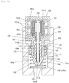
- Figs. 1 and 2 are a sectional view illustrating an example of a flow rate control valve according to the present invention.
- the flow rate control valve includes a body 100, a motor as a driving source (stepping motor) 101, and a valve body 102.
- the body 100 is formed in a cylindrical shape, and a cylindrical motor mounting portion 103 and a cylindrical valve body mounting portion 104 are consecutively provided in an axial direction in the body 100.
- the cylindrical motor mounting portion 103 mounts the motor 101.
- a diameter of the cylindrical valve body mounting portion 104 is smaller than a diameter of the motor mounting portion 103.
- the motor 101 is provided in a motor case 105.
- the inside of the motor case 105 is formed in a cylindrical hollow columnar shape, and on an inner peripheral surface side of the motor case 105, annular two coils 101a along the inner peripheral surface are provided back and forth along an axial direction as a stator of the motor 101.
- the coils 101a are supported by a coil support member 101c in a state in which the coils 101a are wound around a coil bobbin 101b.
- a rotor 101e On an inner side of the annular coils 101a, a rotor 101e is provided in which a cylindrical magnet 101d is fixed on an outer periphery.
- the rotor 101e rotates around a stator, a stator and a rotor form a motor, and the rotor 101e including the magnet 101d is rotated by an electromagnetic force.
- the inside of the rotor 101e is formed in a cylindrical hollow columnar shape, and a projecting portion 101f is formed at one end (lower end) of the rotor 101e, and a through hole is formed to the projecting portion 101f.
- a rotating shaft 106 which is a rotating axis of a rotor is inserted through the through hole, and the rotating shaft 106 is fixed.
- one end (lower end) of the rotor 101e is projected in a flange shape on an outer peripheral side, and one end side of the cylindrical magnet 101d is positioned.
- An outer peripheral surface of the flange-like portion and an outer peripheral surface of the magnet 101d have a substantially same-size outer diameter and are coaxially arranged.
- the rotating shaft 106 is a round rod member. If a tip of the projecting portion 101f of the rotor 101e is a substantial center, one end side (lower end side) is extended in the body 100 from the motor case 105. Further, another end side (upper end side) of the rotating shaft 106 is disposed on an inner side of the rotor 101e.
- a male screw 106a is formed on an outer peripheral surface of one end side of the rotating shaft 106.
- a portion other than the male screw 106a is a shaft 106b.
- a diameter of the male screw 106a is larger than a diameter of the shaft 106b, and the male screw 106a has a wider shape than other portions of the rotating shaft 106.
- a female screw 114a of the valve body 102 is screwed to the male screw 106a as described below.
- a center of the rotating shaft 106 is supported by the projecting portion 101f, and the projecting portion 101f is rotationally supported by a bearing 107 of the motor case 105.
- the bearing 107 is integrally illustrated with the motor case 105. However, the bearing 107 may be separated from the motor case 105.
- another end (upper end) of the rotating shaft 106 is disposed on an inner side of the rotor 101e as described above and rotationally supported by a shaft support portion 108.
- the shaft support portion 108 functions as a sliding bearing and also functions as a radial bearing and a thrust bearing.
- a rotation center of the rotating shaft 106 is regulated by the shaft support portion 108, and also movement in a direction from one end to another end of the rotating shaft 106 along an axial direction of the rotating shaft 106 is regulated. Movement in an opposite direction is regulated by a compression coil spring 122 as an energizing member as described later.
- the male screw 106a provided at one end of the rotating shaft 106 is screwed to the valve body 102, and the valve body 102 opens and closes a first opening 110, through which a fluid passes, by moving in an axial direction of the rotating shaft 106 based on rotation of the rotating shaft 106.
- the first opening 110 is formed by an opening disposed at an inner side end of a through hole 109 penetrating from an inner peripheral surface to an outer peripheral surface of the valve body mounting portion 104 of the body 100.
- a plurality of the through holes 109 and the first openings 110 are provided in a circumferential direction of the body 100 at predetermined intervals. Further, the first openings 110 are opened and closed by the valve body 102.
- the valve body 102 includes a valve member 111 and a moving member 112.
- the valve member 111 is formed in a cylindrical shape as illustrated in Fig. 3(a) , and an outer peripheral surface thereof is slidingly contacted to an inner peripheral surface of the valve body mounting portion 104 (refer to Figs. 1 and 2 ). Therefore, the first opening 110 is opened and closed by the outer peripheral surface (outer periphery) of the valve member 111.
- valve member 111 is circularly opened, and a disk-shaped closing plate 111a is provided to another end.
- a round-shaped through hole 111b is formed at a center of the closing plate 111a.
- four rectangular through holes 111c radially disposed with respect to the through hole 111b are formed on the closing plate 111a. These four through holes 111c are disposed in a circumferential direction at equal intervals.
- each of the ribs 113 includes a circular-arc peripheral wall portion 113a and linear wall portions 113b and 113b formed on both ends of the peripheral wall portion 113a.
- Inner peripheral surfaces of the four peripheral wall portions 113a of the four ribs 113 are consecutively formed with an inner peripheral surface of the round-shaped through hole 111b in an axial direction, and surfaces of the wall portions 113b and 113b facing in a circumferential direction are formed consecutively with surfaces of the rectangular through holes 111c facing in a circumferential direction, in an axial direction.
- the moving member 112 includes a cylindrical main body 114, an abutting portion 115 provided at one end of the main body 114, and a regulating portion 116 provided at another end of the main body 114.
- the female screw 114a is formed on an inner peripheral surface of a cylindrical hole in the main body 114, and a male screw 106a, which is an end of the rotating shaft 106, is screwed to the female screw 114a.
- An end of the hole in which the female screw 114a is formed is closed and becomes an abutting surface (abutting portion) 114b, and one end surface of the rotating shaft 106 can abut on the abutting surface 114b.
- an outer diameter of the main body 114 is almost same as or slightly smaller than an inner diameter of the through hole 111b provided to the closing plate 111a of the valve member 111. Therefore, the main body 114 can be inserted into the valve member 111 through the through hole 11b.
- the abutting portion 115 abuts on a second opening 118 to be described later, and the valve body 102 in a valve-closed state is positioned. Further, the abutting portion 115 includes a locking portion 115a. The rib 113 of the valve member 111 abuts on the locking portion 115a, and the locking portion 115a prevents from the valve member 111 coming off from the moving member 112 by the.
- abutting portions 115 are provided at one end of the main body 114 in a circumferential direction at equal intervals, and four flow passages 117 are provided at equal intervals in a circumferential direction between abutting portions 115 and 115 adjacent to each other in the circumferential direction.
- the abutting portion 115 is formed by cutting off a prefix conical portion provided at a tip of the main body 114 at a part of the flow passage 117, and the abutting surface (locking portion) 115a facing on the regulating portion 116 side of the abutting portion 115 can abut on the rib 113.
- the abutting portion 115 is formed in a size capable of passing through the rectangular through hole 111c formed on the closing plate 111a of the body 100, and a surface of the abutting portion 115, which faces on the regulating portion 116 side and is orthogonal to the main body 114, is the locking portion 115a (abutting surface). Therefore, when the main body 114 rotates at 45° around an axis after the abutting portion 115 has passed through the through hole 111c, the locking portion 115a of the abutting portion 115 can abut on the rib 113.
- an inclined surface 115b inclined with respect to an axis of the main body 114 of the abutting portion 115 is inclined so as to approach on an axial side of the main body 114 (valve body 102) as moving on one end side of the main body 114 (valve body 102).
- a through hole (suction hole) 119 is provided at a center of the closing plate provided at one end (lower end) of the body 100, and the first opening 118 is provided at an opening edge of an inner side end of the suction hole 119.
- each of the four abutting portions 115 can abut on the first opening 118. Specifically, one end of the moving member 112 is inserted into the suction hole 119, and the inclined surface 115b abuts on the first opening 118. Consequently, further movement of the moving member 112 is regulated. Therefore, the inclined surface 115b is a stopper surface for regulating movement of the moving member 112, and accordingly the valve body 102 in a valve-closed state is positioned.
- the flow passage 117 is provided between the first opening 118 and the main body 114, and a fluid (air) can flow through the flow passage 117.
- the regulating portion 116 abuts on the valve member 111 and regulates movement of the valve member 111 to another end side of the rotating shaft 106.
- four regulating portions 116 are provided in a circumferential direction at equal intervals by cutting off four portions of a disk-shaped flange portion, which is provided at another end of the main body 114, in a circumferential direction at equal intervals in a rectangular shape each, and a notch 120 is formed between the regulating portions 116 and 116 adjacent to each other in a circumferential direction.
- the notch 120 is provided on an extension line in an axial direction of the flow passage 117, and a shape and a size of the notch 120 are substantially same as four rectangular through holes 111c provided on the closing plate 111a of the valve member 111.
- the locking portion 115a of the abutting portion 115 can abut on the rib 113 by rotating the main body 114 around an axis at 45° after the abutting portion 115 has passed through the through hole 111c of the valve member 111.
- the rectangular through hole 111c and the notch 120 are overlapped in an axial direction of the moving member 112, and the regulating portion 116 can abut on the closing plate 111a of the valve member 111 between the rectangular through holes 111c and 111c adjacent to each other in a circumferential direction. Therefore, movement of the rotating shaft 106 of the valve member 111 to another end side can be regulated by the regulating portion 116.
- a regulating member 121 is provided which is engaged with the valve body 102 and regulates rotation of the valve body 102 around an axis.
- four columnar regulating members 121 are provided in a circumferential direction at equal intervals on a disk 105a fixed on another end surface of the motor case 105 as illustrated in Fig. 5 .
- 121 extend to the valve body mounting portion 104 in parallel with the rotating shaft 106 (refer to Figs. 1 and 2 ) and disposed at equal intervals in a circumferential direction on an outer peripheral side of the projecting portion 101f in which the rotating shaft 106 is inserted.
- a sectional shape of the regulating member 121 almost same as or slightly smaller than the rectangular through hole 111c and the notch 120, and in the case where the through hole 111c and the notch 120 are overlapped in an axial direction of the moving member 112, the regulating member 121 is inserted into the through hole 111c and the notch 120 and engaged with the valve member 111 and moving member 112, in other words, engaged with the valve body 102.
- the regulating member 121 is fixed to the motor case 105 via the disk 105a and therefore can regulate rotation of the valve body 102 around an axis.
- a length of the regulating member 121 is set such that a lower end of the regulating portion 121 can be inserted into the four through holes 111c of the valve member 111, in the case where the moving member 112 moves upward, and a lower end surface of the rotating shaft 106 abuts on the abutting surface 114b in the moving member 112 (in the case where the moving member 112 is closest to the motor 101). Therefore, in such a state, rotation of the valve member 111 around an axis is regulated by the regulating member 112, and the rib 113 of the valve member 111 abuts on the locking portion 115a of the moving member 112. Consequently the valve member 111 is prevented from coming off from the moving member 112, in other words, from the motor 101.
- the compression coil spring (energizing member) 122 is provided on one end side (lower end side) in the body 100, in other words, to the valve body mounting portion 104.
- One end (lower end) of the compression coil spring 122 is disposed around the suction port 118 on a bottom surface of the valve body mounting portion 104, and another end (lower end) thereof is inserted into the cylindrical valve member 111 and compressed on an outer side of the rib 113 on a back surface of the closing plate 111a of the valve member 111. Therefore, the valve member 111 is energized on another end side (lower end side) of the rotating shaft 106 by the compression coil spring 122.
- a state in which the valve body 102 is positioned on an upper side, and one end surface (lower end surface) of the rotating shaft 106 abuts on the abutting surface 114b provided at a lower end of a hole in which the female screw 114a of the moving member 112 is provided is a valve-open position in which the first opening 110 of the discharge hole 109 is opened.
- a state in which the valve body 102 is positioned on a lower side, and the inclined surface 115b on one end (lower end) of the moving member 112 abuts on the second opening 118 of the suction hole 119 is a valve-closed position in which the second opening 118 is closed.
- the valve body 102 is assembled to the motor 101, first the female screw 114a of the moving member 112 is screwed to the male screw 106a provided at one end (lower end) of the rotating shaft 106 of the motor 101. Accordingly, the moving member 112 is engaging with the rotating shaft 106, and four regulating members 121 are inserted into four notches 120 provided at another end of the moving member 112. Rotation of the moving member 112 is regulated by the regulating member 121.
- the moving member 112 is inserted into the valve member 111.
- the valve member 111 is fitted outside of the moving member 112.
- the moving member 112 (main body 114) is rotated around an axis at 45°. Accordingly, the locking portion 115a of the abutting portion 115 faces the rib 113 of the valve member 111 and can abut on the rib 113, and the regulating member 121 fits to the through hole 111c of the valve member 111 in a circumferential direction.
- the regulating member 121 is inserted into the through hole 111c by further inserting the moving member 112 into the valve member 111 (fitting the valve member 111 to the outside of the moving member 112). Consequently, rotation of the valve member 111 is regulated.
- the compression coil spring 122 is inserted into the valve body mounting portion 104 of the body 100 and disposed on a bottom surface of the valve body mounting portion 104.
- valve body 102 including the moving member 112 and the valve member 111 prevented from coming off from the moving member 112 are mounted to the valve body mounting portion 104, and an upper end of the compression coil spring 122 abuts on the closing plate 111a of the valve member 111. In this state, the compression coil spring 122 is not compressed.
- valve member 111 As the valve body 102 is mounted in the valve body mounting portion 104, the valve member 111 is moved by pushing to the upper side (another end side of the rotating shaft 106) by the compression coil spring 122. In this case, the compression coil spring 112 is slightly compressed by the own weight of the valve member 111.
- valve member 111 moves upward by a predetermined distance, the valve member 111 abuts on the regulating portion 116 of the moving member 112, and further movement of the valve member 111 to the upper side (another end side of the rotating shaft 106) is regulated.
- one end surface (lower end surface) of the regulating member 121 is positioned lower than one end surface (lower end surface) of the valve member 111.
- the compression coil spring 122 is fully extended at a position where the valve member 111 is moved upward by a predetermined distance from the position where the discharge hole 110 formed to the body 100 is fully opened. Therefore, a predetermined amount of the compression coil spring 122 is compressed by moving down the valve body 102 with the motor case 105 by a predetermined distance from this state. In this case, the valve body 102 is moved downward such that the discharge hole 110 is not closed by the valve member 111.
- valve body 102 is assembled to the motor 101 by fixing the motor case 105 to the motor mounting portion 103. In such a state, the valve body 102 is always energized upward by the compression coil spring 122. The rotating shaft 106 is screwed to the moving member 112 of the valve body 102. Therefore, the upward energizing force is applied to the rotating shaft 106 and further to the shaft support portion 108.
- the valve body 102 opens the first opening 110 of the discharge hole 109 when an engine is in an idling state.
- the rotating shaft 106 is rotated in a normal direction by the motor 101.
- the moving member 112 starts moving upward in an axial line direction, and the valve member 111 starts moving upward with the moving member 112 (at the same timing with the moving member 112).
- an outer peripheral surface of the valve body 102 opens the first opening 110.
- the moving member 112 moves upward until the abutting surface 114b of a hole, in which the female screw 114a is formed, abuts on one end surface (lower end surface) of the rotating shaft 106, and rotation of the rotating shaft 106 by the motor 101 is stopped when the abutting surface 114b abuts on the end surface. Then, one end (lower end) of the moving member 112 is completely separated from the first opening 118 of the suction hole 119, and the first opening 118 is fully opened.
- valve member 111 closes the first opening 110 of the discharge hole 109 in the case where the valve body 102 is at a valve-open position.
- the moving member 112 starts moving downward in an axial line direction
- the valve member 111 starts moving downward with the moving member 112 (at the same timing with the moving member 112).
- an outer peripheral surface of the valve member 111 closes the first opening 110.
- valve body 102 further downward movement of the moving member 112 is regulated when the inclined surface 115b provided at one end (lower end) of the moving member 112 abuts on the first opening 118 of the suction hole 119 after or at the same tirne when the valve member 111 closes the discharge hole 110.
- the flow passage 117 is provided between the second opening 118 and the main body 114, and a fluid (air) can flow through the flow passage 117.
- the female screw 114a of the moving member 112 is screwed to the male screw 106a provided at one end of the rotating shaft 106 which can be rotated by the motor 101, the moving member 112 is inserted into the valve member 111, the valve member 111 is abutted on the locking portion 115a and prevented from coming off from the moving member 112, the compression coil spring 122 is provided to the valve body mounting portion 104 in the body 100, and the compression coil spring 122 is stably held in the body 100. Then, by disposing the valve member 111 to the compression coil spring 122, the valve body 102 can be easily assembled to the motor 101.
- valve member 111 prevented from coming off from the moving member 112 is pulled out from the body 100 with the moving member 112 and separated from the compression coil spring 122, and then the moving member 112 is moved downward by rotating the rotating shaft 106 by the motor 101. Accordingly, rotation regulation of the valve member 111 by the regulating member 121 is released. Then, by rotating the valve member 111 around an axis at 45°, locking of the valve member 111 is released, and the valve member 111 is removed from the moving member 112, and also by removing the moving member 121 from the rotating shaft 106, the valve body 102 is easily removed.
- the moving member 112 can be inserted into the valve member 111, and by inserting the moving member 112 into the valve member 111 and relatively rotating them around an axis at a predetermined angle (45°), the valve member 111 can abut on the locking portion 115a, and the valve member 111 is certainly prevented from coming off from the motor 101 when the valve body 102 is assembled to the motor 101.
- the regulating member 121 which is engaged with the valve body 102 and regulates rotation of the valve body 102 around an axis is fixed to the motor case 105. Therefore, in the case where the rotating shaft 106 is rotated in normal and reverse directions by the motor 101, the regulating member 121 regulates rotation around an axis of the valve body 102 by being engaged with the valve body 102, and consequently the valve body 102 can be certainly moved along an axial direction of the rotating shaft 106.
- the regulating member 121 regulates rotation of the valve member 111 around an axis, and the valve member 111 is certainly prevented from coming off from the moving member 112.
- the rotating shaft 106 rotates, and the valve body 102 is moved in an axial direction of the rotating shaft 106.
- the first opening 110 is closed by the outer periphery of the valve member 111 of the valve body 102, and the abutting portion 115 provided at one end of the moving member 112 of the valve body 102 abuts on the second opening 118 which is a suction port. Accordingly, an accurate valve-closed position of the valve body 102 can be secured.
- the flow passage 117 is provided to one end of the moving member 112, and a fluid can flow through the flow passage 117. Therefore, the flow passage can be secured without closing the suction port (second opening) 118 in a valve-closed state.
- abutting portions 115 are provided at predetermined intervals in a circumferential direction of the moving member 112 of the valve body 102, and the flow passage 117 is provided between the abutting portions 115 and 115 adjacent to each other in the circumferential direction. Therefore, an accurate valve-closed position of the valve body can be easily secured, and a fluid flows in the flow passage 17 provided between the abutting portions 115 and 115 adjacent to each other in the circumferential direction. Consequently, the flow passage can be certainly secured without closing the suction port 118 in a valve-closed state.
- the inclined surface 115b abutting on the second opening 118 is formed to the abutting portion 115, and therefore, even if a diameter of the second opening 118 is varied, the inclined surface 115b certainly abuts on the second opening 118, and an accurate valve-closed position of the valve body 102 can be certainly secured.
- the abutting surface (abutting portion) 114b which abuts on one end of the rotating shaft 106 is provided in a hole in the moving member 112 of the valve body 102 in the case where the valve body 102 is moved on another end side in an axial direction of the rotating shaft 106, and the first opening 110 is fully opened by the outer periphery of the valve member 111. Therefore, if the first opening 110 is fully opened by the outer periphery of the valve member 111, the abutting surface (abutting portion) 114b abuts on one end of the rotating shaft 106. Therefore, an accurate valve-open position of the valve body 102 can be secured.
- the abutting portion 115 can be inserted into the second opening 118.
- a moving amount of the valve body 102 can be increased without enlarging the valve body, and a control width of the valve body 102 can be increased even if the valve body is downsized.
Landscapes
- Engineering & Computer Science (AREA)
- General Engineering & Computer Science (AREA)
- Mechanical Engineering (AREA)
- Chemical & Material Sciences (AREA)
- Combustion & Propulsion (AREA)
- Physics & Mathematics (AREA)
- Fluid Mechanics (AREA)
- Electrically Driven Valve-Operating Means (AREA)
Abstract
Description
- The present invention relates to a flow rate control valve which controls a flow rate of a fluid by operating by rotation of a driving source such as a motor.
- Conventionally, in a vehicle such as an automobile and a motorcycle, for example, in the case of an engine in which fuel injection and ignition are controlled by an electronic controller, an idling speed control valve (ISCV) which is another electronically controlled air control valve is provided on a side of a throttle valve. The ISCV controls idle-up and stabilize idling when an air condition is operated. Specifically, for example, the ISCV controls an intake air amount to the engine and controls the engine to keep a target rotation speed during idling when a vehicle is in an idling state by tightening the throttle valve.
- The ISCV, for example, includes a stepping motor, a rotating shaft of the stepping motor, and a valve body. The stepping motor works as an actuator which actuates a valve. The valve body includes a screw mechanism between the shaft and moves in an axial direction of the shaft. A top side of the shaft is a male screw, a nut provided to the valve body is screwed to the male screw, and based on normal/reverse rotations of the shaft, a flow rate of intake air to an engine during idling is controlled when the valve body is moved to an axial direction of the shaft.
- A flow rate control valve described in Patent Literature 1 is known as an example of the above-described flow rate control valve. When the flow rate control valve is assembled, a valve body is assembled to a stepping motor which is a driving source while compressing a spring which energizes the valve body in one direction. Further, when the flow rate control valve is disassembled, the valve body is removed from the stepping motor while compressing the spring.
- Patent Literature 1:
JP 2007-332904 A - When the conventional flow rate control valve is assembled, a valve body is assembled to a stepping motor while compressing a spring and rotating the valve body, and also when the flow rate control valve is disassembled, the valve body is removed from the stepping motor while compressing the spring and rotating the valve body. Therefore, it is difficult to assemble and remove a valve body to and from a stepping motor.
- The present invention is in view of the above circumstances, and an object of the present invention is to provide a flow rate control valve in which a valve body can be easily assembled and removed from a driving source such as a motor (stepping motor) and also can be easily removed.
- To achieve the above-described object, a flow rate control valve according to the present invention includes a body, a rotating shaft, a valve body, and an energizing member. In the body, a driving source is mounted. The rotating shaft is provided in the body and rotatable in normal and reverse directions by the driving source. The valve body is engaged with one end of the rotating shaft and opens and closes an opening through which a fluid passes by moving along an axial direction of the rotating shaft based on rotation of the rotating shaft. The energizing member which energizes the valve body to another end side of the rotating shaft. The valve body includes a cylindrical valve member and a moving member. The cylindrical valve member opens and closes the opening. The moving member is movably inserted into the valve member in an axial direction of the shaft, engaged with one end of the rotating shaft, and moves along an axial direction of the rotating shaft based on rotation of the rotating shaft. A locking portion is provided by which the valve member is prevented from coming off from the moving member when the valve member abuts on one end of the moving member. A regulating portion is provided which regulates movement of the valve member to another end side of the rotating shaft when the valve member abuts on another end of the moving member. The valve member is energized on another end side of the rotating shaft by the energizing member provided on one end side in the body.
- In the present invention, in the case where a valve body is assembled to a driving source, a moving member is engaged with one end of a rotatable rotating shaft by the driving source, the moving member is inserted into the valve member, the valve member is abutted on a locking portion, the valve member is prevented from coming off from the moving member, the energizing member is provided on one end side in the body, and the energizing member is stably held in a body. Then, the valve member prevented from coming off from the moving member is disposed to the energizing member, and the valve body can be easily assembled to the driving source.
- On the other hand, in the case where the valve body is removed, the valve member prevented from coming off from the moving member is pulled out from the body with the moving member, the valve member is removed from the moving member by releasing coming-off prevention of the valve member, further the moving member is removed from the rotating shaft, and accordingly the valve body can be easily removed.
- In the above-described configuration of the present invention, in a state in which the moving member is inserted into the valve member and rotated at a predetermined angle around an axis, the locking portion preferably abuts on one end of the moving member.
- According to such a configuration, in a state in which the valve member and the moving member rotate at a predetermined angle around an axis, the locking portion abuts on one end of the moving member and prevents the valve body from coming off from the moving direction. Therefore, the valve member can be certainly prevented from coming off from the moving member when a valve body is assembled to a motor.
- Further, in the above-described configuration of the present invention, in the body, a regulating member is provided which is engaged with the valve body and regulates rotation around an axis of the valve body.
- The regulating member preferably regulates rotation around an axis of the valve member in a state in which the moving member is inserted into the valve member and rotates at a predetermined angle around an axis.
- According to such a configuration, in the case where a rotating shaft is rotated in normal and reverse directions by a driving source, a regulating member is engaged with a valve body and regulates rotation around an axis of the valve body. Therefore, the valve body can be certainly moved along an axial direction of the rotating shaft.
- Further, in the case where the valve member is prevented from coming off by a locking portion, the regulating member regulates rotation around an axis of the valve member, and therefore the valve member can be certainly prevented from coming off form the moving member.
- According to the present invention, a moving member is engaged with one end of a rotatable rotating shaft, the moving member is inserted into the valve member, the valve member is abutted on the locking portion and prevented from coming off, and the energizing member is provided on one end side in the body. On the other hand, an energizing member is disposed to the valve member, and the valve body is easily assembled to the driving source.
- Further, the valve member prevented from coming off is pulled out from the body with the moving member, the valve member is removed from the moving member by releasing coming-off prevention of the valve member, further the moving member is removed from the rotating shaft, and the valve body can be easily removed.
-
-
Fig. 1 illustrates an example of a flow rate control valve according to the present invention and is a longitudinal sectional view of the flow rate control valve in a valve-open state. -
Fig. 2 illustrates an example of the flow rate control valve according to the present invention and is a longitudinal sectional view of the flow rate control valve in a valve-closed state. -
Figs. 3(a) and 3(b) illustrate an example of the flow rate control valve according to the present invention,Fig. 3 (a) is a perspective view of a valve member which is partially cut off, andFig. 3(b) is a back view of the valve member. -
Fig. 4 illustrates an example of the flow rate control valve according to the present invention and is a perspective view of a moving member. -
Fig. 5 illustrates an example of the flow rate control valve according to the present invention and is a perspective view of a regulating member provided to a motor case. -
Fig. 6 illustrates an example of the flow rate control valve according to the present invention and is a perspective view illustrating a motor and the moving member in which the valve member is attached. - Hereinafter, an embodiment of the present invention will be described with reference to drawings. In the description below, a description regarding a vertical direction such as an upper end and a lower end is for simplifying an understanding by the drawings and is not for limiting such as a mounting attitude of a flow rate control valve.
-
Figs. 1 and2 are a sectional view illustrating an example of a flow rate control valve according to the present invention. As illustrated inFigs. 1 and2 , the flow rate control valve includes abody 100, a motor as a driving source (stepping motor) 101, and avalve body 102. - The
body 100 is formed in a cylindrical shape, and a cylindricalmotor mounting portion 103 and a cylindrical valvebody mounting portion 104 are consecutively provided in an axial direction in thebody 100. The cylindricalmotor mounting portion 103 mounts themotor 101. A diameter of the cylindrical valvebody mounting portion 104 is smaller than a diameter of themotor mounting portion 103. - The
motor 101 is provided in amotor case 105. The inside of themotor case 105 is formed in a cylindrical hollow columnar shape, and on an inner peripheral surface side of themotor case 105, annular twocoils 101a along the inner peripheral surface are provided back and forth along an axial direction as a stator of themotor 101. Thecoils 101a are supported by acoil support member 101c in a state in which thecoils 101a are wound around acoil bobbin 101b. - On an inner side of the
annular coils 101a, arotor 101e is provided in which acylindrical magnet 101d is fixed on an outer periphery. Therotor 101e rotates around a stator, a stator and a rotor form a motor, and therotor 101e including themagnet 101d is rotated by an electromagnetic force. - Further, the inside of the
rotor 101e is formed in a cylindrical hollow columnar shape, and a projectingportion 101f is formed at one end (lower end) of therotor 101e, and a through hole is formed to the projectingportion 101f. Arotating shaft 106 which is a rotating axis of a rotor is inserted through the through hole, and therotating shaft 106 is fixed. Further, one end (lower end) of therotor 101e is projected in a flange shape on an outer peripheral side, and one end side of thecylindrical magnet 101d is positioned. An outer peripheral surface of the flange-like portion and an outer peripheral surface of themagnet 101d have a substantially same-size outer diameter and are coaxially arranged. - The
rotating shaft 106 is a round rod member. If a tip of the projectingportion 101f of therotor 101e is a substantial center, one end side (lower end side) is extended in thebody 100 from themotor case 105. Further, another end side (upper end side) of therotating shaft 106 is disposed on an inner side of therotor 101e. - Furthermore, a
male screw 106a is formed on an outer peripheral surface of one end side of therotating shaft 106. Here, a portion other than themale screw 106a is ashaft 106b. - In the
rotating shaft 106, a diameter of themale screw 106a is larger than a diameter of theshaft 106b, and themale screw 106a has a wider shape than other portions of therotating shaft 106. Afemale screw 114a of thevalve body 102 is screwed to themale screw 106a as described below. - Further, a center of the
rotating shaft 106 is supported by the projectingportion 101f, and the projectingportion 101f is rotationally supported by a bearing 107 of themotor case 105. InFig. 1 , thebearing 107 is integrally illustrated with themotor case 105. However, thebearing 107 may be separated from themotor case 105. - Further, another end (upper end) of the
rotating shaft 106 is disposed on an inner side of therotor 101e as described above and rotationally supported by ashaft support portion 108. Theshaft support portion 108 functions as a sliding bearing and also functions as a radial bearing and a thrust bearing. Specifically, a rotation center of therotating shaft 106 is regulated by theshaft support portion 108, and also movement in a direction from one end to another end of therotating shaft 106 along an axial direction of therotating shaft 106 is regulated. Movement in an opposite direction is regulated by acompression coil spring 122 as an energizing member as described later. - The
male screw 106a provided at one end of therotating shaft 106 is screwed to thevalve body 102, and thevalve body 102 opens and closes afirst opening 110, through which a fluid passes, by moving in an axial direction of therotating shaft 106 based on rotation of therotating shaft 106. Thefirst opening 110 is formed by an opening disposed at an inner side end of a throughhole 109 penetrating from an inner peripheral surface to an outer peripheral surface of the valvebody mounting portion 104 of thebody 100. - A plurality of the through
holes 109 and thefirst openings 110 are provided in a circumferential direction of thebody 100 at predetermined intervals. Further, thefirst openings 110 are opened and closed by thevalve body 102. - The
valve body 102 includes avalve member 111 and a movingmember 112. - The
valve member 111 is formed in a cylindrical shape as illustrated inFig. 3(a) , and an outer peripheral surface thereof is slidingly contacted to an inner peripheral surface of the valve body mounting portion 104 (refer toFigs. 1 and2 ). Therefore, thefirst opening 110 is opened and closed by the outer peripheral surface (outer periphery) of thevalve member 111. - Further, one end of the
valve member 111 is circularly opened, and a disk-shapedclosing plate 111a is provided to another end. As illustrated inFig. 3(b) , a round-shaped throughhole 111b is formed at a center of theclosing plate 111a. Further, four rectangular throughholes 111c radially disposed with respect to the throughhole 111b are formed on theclosing plate 111a. These four throughholes 111c are disposed in a circumferential direction at equal intervals. - Further, as illustrated in
Fig. 3(a) , fourribs 113 are projected in a circumferential direction at equal intervals on a back surface of theclosing plate 111a. Each of theribs 113 includes a circular-arcperipheral wall portion 113a andlinear wall portions peripheral wall portion 113a. Inner peripheral surfaces of the fourperipheral wall portions 113a of the fourribs 113 are consecutively formed with an inner peripheral surface of the round-shaped throughhole 111b in an axial direction, and surfaces of thewall portions holes 111c facing in a circumferential direction, in an axial direction. - As illustrated in
Fig. 4 , the movingmember 112 includes a cylindricalmain body 114, an abuttingportion 115 provided at one end of themain body 114, and a regulatingportion 116 provided at another end of themain body 114. - As illustrated in
Figs. 1 and2 , thefemale screw 114a is formed on an inner peripheral surface of a cylindrical hole in themain body 114, and amale screw 106a, which is an end of therotating shaft 106, is screwed to thefemale screw 114a. An end of the hole in which thefemale screw 114a is formed is closed and becomes an abutting surface (abutting portion) 114b, and one end surface of therotating shaft 106 can abut on theabutting surface 114b. - Further, an outer diameter of the
main body 114 is almost same as or slightly smaller than an inner diameter of the throughhole 111b provided to theclosing plate 111a of thevalve member 111. Therefore, themain body 114 can be inserted into thevalve member 111 through the through hole 11b. - In the case where the
first opening 110 is fully closed by an outer periphery of thevalve member 111, the abuttingportion 115 abuts on asecond opening 118 to be described later, and thevalve body 102 in a valve-closed state is positioned. Further, the abuttingportion 115 includes a lockingportion 115a. Therib 113 of thevalve member 111 abuts on the lockingportion 115a, and the lockingportion 115a prevents from thevalve member 111 coming off from the movingmember 112 by the. - As illustrated in
Fig. 4 , four abuttingportions 115 are provided at one end of themain body 114 in a circumferential direction at equal intervals, and fourflow passages 117 are provided at equal intervals in a circumferential direction between abuttingportions portion 115 is formed by cutting off a prefix conical portion provided at a tip of themain body 114 at a part of theflow passage 117, and the abutting surface (locking portion) 115a facing on the regulatingportion 116 side of the abuttingportion 115 can abut on therib 113. - Further, the abutting
portion 115 is formed in a size capable of passing through the rectangular throughhole 111c formed on theclosing plate 111a of thebody 100, and a surface of the abuttingportion 115, which faces on the regulatingportion 116 side and is orthogonal to themain body 114, is the lockingportion 115a (abutting surface). Therefore, when themain body 114 rotates at 45° around an axis after the abuttingportion 115 has passed through the throughhole 111c, the lockingportion 115a of the abuttingportion 115 can abut on therib 113. - Further, an
inclined surface 115b inclined with respect to an axis of themain body 114 of the abuttingportion 115 is inclined so as to approach on an axial side of the main body 114 (valve body 102) as moving on one end side of the main body 114 (valve body 102). - Further, as illustrated in
Figs. 1 and2 , a through hole (suction hole) 119 is provided at a center of the closing plate provided at one end (lower end) of thebody 100, and thefirst opening 118 is provided at an opening edge of an inner side end of thesuction hole 119. - The
inclined surface 115b of each of the four abuttingportions 115 can abut on thefirst opening 118. Specifically, one end of the movingmember 112 is inserted into thesuction hole 119, and theinclined surface 115b abuts on thefirst opening 118. Consequently, further movement of the movingmember 112 is regulated. Therefore, theinclined surface 115b is a stopper surface for regulating movement of the movingmember 112, and accordingly thevalve body 102 in a valve-closed state is positioned. - Further, in a state in which the
inclined surface 115b abuts on thefirst opening 118, theflow passage 117 is provided between thefirst opening 118 and themain body 114, and a fluid (air) can flow through theflow passage 117. - The regulating
portion 116 abuts on thevalve member 111 and regulates movement of thevalve member 111 to another end side of therotating shaft 106. As illustrated inFig. 4 , four regulatingportions 116 are provided in a circumferential direction at equal intervals by cutting off four portions of a disk-shaped flange portion, which is provided at another end of themain body 114, in a circumferential direction at equal intervals in a rectangular shape each, and anotch 120 is formed between the regulatingportions - The
notch 120 is provided on an extension line in an axial direction of theflow passage 117, and a shape and a size of thenotch 120 are substantially same as four rectangular throughholes 111c provided on theclosing plate 111a of thevalve member 111. - The locking
portion 115a of the abuttingportion 115 can abut on therib 113 by rotating themain body 114 around an axis at 45° after the abuttingportion 115 has passed through the throughhole 111c of thevalve member 111. Further, the rectangular throughhole 111c and thenotch 120 are overlapped in an axial direction of the movingmember 112, and the regulatingportion 116 can abut on theclosing plate 111a of thevalve member 111 between the rectangular throughholes rotating shaft 106 of thevalve member 111 to another end side can be regulated by the regulatingportion 116. - Further, as illustrated in
Figs. 1 and2 , in thebody 100, a regulatingmember 121 is provided which is engaged with thevalve body 102 and regulates rotation of thevalve body 102 around an axis. Specifically, fourcolumnar regulating members 121 are provided in a circumferential direction at equal intervals on adisk 105a fixed on another end surface of themotor case 105 as illustrated inFig. 5 . The regulating members - 121 extend to the valve
body mounting portion 104 in parallel with the rotating shaft 106 (refer toFigs. 1 and2 ) and disposed at equal intervals in a circumferential direction on an outer peripheral side of the projectingportion 101f in which therotating shaft 106 is inserted. - Further, a sectional shape of the regulating
member 121 almost same as or slightly smaller than the rectangular throughhole 111c and thenotch 120, and in the case where the throughhole 111c and thenotch 120 are overlapped in an axial direction of the movingmember 112, the regulatingmember 121 is inserted into the throughhole 111c and thenotch 120 and engaged with thevalve member 111 and movingmember 112, in other words, engaged with thevalve body 102. The regulatingmember 121 is fixed to themotor case 105 via thedisk 105a and therefore can regulate rotation of thevalve body 102 around an axis. - As illustrated in
Fig. 6 , a length of the regulatingmember 121 is set such that a lower end of the regulatingportion 121 can be inserted into the four throughholes 111c of thevalve member 111, in the case where the movingmember 112 moves upward, and a lower end surface of therotating shaft 106 abuts on theabutting surface 114b in the moving member 112 (in the case where the movingmember 112 is closest to the motor 101). Therefore, in such a state, rotation of thevalve member 111 around an axis is regulated by the regulatingmember 112, and therib 113 of thevalve member 111 abuts on the lockingportion 115a of the movingmember 112. Consequently thevalve member 111 is prevented from coming off from the movingmember 112, in other words, from themotor 101. - Further, as illustrated in
Figs. 1 and2 , the compression coil spring (energizing member) 122 is provided on one end side (lower end side) in thebody 100, in other words, to the valvebody mounting portion 104. One end (lower end) of thecompression coil spring 122 is disposed around thesuction port 118 on a bottom surface of the valvebody mounting portion 104, and another end (lower end) thereof is inserted into thecylindrical valve member 111 and compressed on an outer side of therib 113 on a back surface of theclosing plate 111a of thevalve member 111. Therefore, thevalve member 111 is energized on another end side (lower end side) of therotating shaft 106 by thecompression coil spring 122. - As illustrated in
Fig. 1 , a state in which thevalve body 102 is positioned on an upper side, and one end surface (lower end surface) of therotating shaft 106 abuts on theabutting surface 114b provided at a lower end of a hole in which thefemale screw 114a of the movingmember 112 is provided is a valve-open position in which thefirst opening 110 of thedischarge hole 109 is opened. As illustrated inFig. 2 , a state in which thevalve body 102 is positioned on a lower side, and theinclined surface 115b on one end (lower end) of the movingmember 112 abuts on thesecond opening 118 of thesuction hole 119 is a valve-closed position in which thesecond opening 118 is closed. - In the case where the
valve body 102 is assembled to themotor 101, first thefemale screw 114a of the movingmember 112 is screwed to themale screw 106a provided at one end (lower end) of therotating shaft 106 of themotor 101. Accordingly, the movingmember 112 is engaging with therotating shaft 106, and four regulatingmembers 121 are inserted into fournotches 120 provided at another end of the movingmember 112. Rotation of the movingmember 112 is regulated by the regulatingmember 121. - In this case, by operating the
motor 101 and rotating therotating shaft 106 in a normal direction, a predetermined length of themale screw 106a of therotating shaft 106 is screwed to thefemale screw 114a of the movingmember 112. - Next, the moving
member 112 is inserted into thevalve member 111. Conversely, thevalve member 111 is fitted outside of the movingmember 112. - In this case, four through
holes 111c of thevalve member 111 are fitted to four abuttingportions 115 of the movingmember 112 in a circumferential direction, and the movingmember 112 is inserted in to thevalve member 111. Therefore, the abuttingportions 115 pass through the throughholes 111c, and themain body 114 passes through the throughhole 111b. - Then, in the case where the abutting
portions 115 pass through the throughholes 111c and pass by therib 113, the moving member 112 (main body 114) is rotated around an axis at 45°. Accordingly, the lockingportion 115a of the abuttingportion 115 faces therib 113 of thevalve member 111 and can abut on therib 113, and the regulatingmember 121 fits to the throughhole 111c of thevalve member 111 in a circumferential direction. - Next, the regulating
member 121 is inserted into the throughhole 111c by further inserting the movingmember 112 into the valve member 111 (fitting thevalve member 111 to the outside of the moving member 112). Consequently, rotation of thevalve member 111 is regulated. - In this state, by operating the
motor 101 again and rotating therotating shaft 106 in a normal direction, one end surface (lower end surface) of therotating shaft 106 is abutted on theabutting surface 114b in the movingmember 112 as illustrated inFig. 6 . - In such a state, rotation of the
valve member 111 around an axis is regulated by the regulatingmember 112, and therib 113 of thevalve member 111 abuts on the lockingportion 115a of the movingmember 112 and is prevented from coming off from the movingmember 112, in other words, from themotor 101. - Next, the
compression coil spring 122 is inserted into the valvebody mounting portion 104 of thebody 100 and disposed on a bottom surface of the valvebody mounting portion 104. - Next, the
valve body 102 including the movingmember 112 and thevalve member 111 prevented from coming off from the movingmember 112 are mounted to the valvebody mounting portion 104, and an upper end of thecompression coil spring 122 abuts on theclosing plate 111a of thevalve member 111. In this state, thecompression coil spring 122 is not compressed. - As the
valve body 102 is mounted in the valvebody mounting portion 104, thevalve member 111 is moved by pushing to the upper side (another end side of the rotating shaft 106) by thecompression coil spring 122. In this case, thecompression coil spring 112 is slightly compressed by the own weight of thevalve member 111. - When the
valve member 111 moves upward by a predetermined distance, thevalve member 111 abuts on the regulatingportion 116 of the movingmember 112, and further movement of thevalve member 111 to the upper side (another end side of the rotating shaft 106) is regulated. - Further, as the
valve member 111 moves upward, one end surface (lower end surface) of the regulatingmember 121 is positioned lower than one end surface (lower end surface) of thevalve member 111. - The
compression coil spring 122 is fully extended at a position where thevalve member 111 is moved upward by a predetermined distance from the position where thedischarge hole 110 formed to thebody 100 is fully opened. Therefore, a predetermined amount of thecompression coil spring 122 is compressed by moving down thevalve body 102 with themotor case 105 by a predetermined distance from this state. In this case, thevalve body 102 is moved downward such that thedischarge hole 110 is not closed by thevalve member 111. - After that, the
valve body 102 is assembled to themotor 101 by fixing themotor case 105 to themotor mounting portion 103. In such a state, thevalve body 102 is always energized upward by thecompression coil spring 122. Therotating shaft 106 is screwed to the movingmember 112 of thevalve body 102. Therefore, the upward energizing force is applied to therotating shaft 106 and further to theshaft support portion 108. - In such a flow rate control valve, the valve body 102 (valve member 111) opens the
first opening 110 of thedischarge hole 109 when an engine is in an idling state. Specifically, as illustrated inFig. 2 , in the case where thevalve body 102 is at a valve-closed position, therotating shaft 106 is rotated in a normal direction by themotor 101. By screw feeding actions of themale screw 106a of therotating shaft 106 and thefemale screw 114a of the movingmember 112, the movingmember 112 starts moving upward in an axial line direction, and thevalve member 111 starts moving upward with the moving member 112 (at the same timing with the moving member 112). Then, as illustrated inFig. 1 , an outer peripheral surface of thevalve body 102 opens thefirst opening 110. - In this case, the moving
member 112 moves upward until theabutting surface 114b of a hole, in which thefemale screw 114a is formed, abuts on one end surface (lower end surface) of therotating shaft 106, and rotation of therotating shaft 106 by themotor 101 is stopped when theabutting surface 114b abuts on the end surface. Then, one end (lower end) of the movingmember 112 is completely separated from thefirst opening 118 of thesuction hole 119, and thefirst opening 118 is fully opened. - Then, air introduced to the
suction port 118 through a piping from a surge tank on an upstream side from a throttle valve flow into the valvebody mounting portion 104, is discharged from thedischarge hole 110, and flows into an engine. - On the other hand, when the engine is not in an idling state, as illustrated in
Fig. 1 , therotating shaft 106 is rotated in a reverse direction by themotor 101, and the valve body 102 (valve member 111) closes thefirst opening 110 of thedischarge hole 109 in the case where thevalve body 102 is at a valve-open position. Specifically, by a screw feeding action of themale screw 106a of therotating shaft 106 and thefemale screw 114a of the movingmember 112, the movingmember 112 starts moving downward in an axial line direction, and thevalve member 111 starts moving downward with the moving member 112 (at the same timing with the moving member 112). Then, as illustrated inFig. 2 , an outer peripheral surface of thevalve member 111 closes thefirst opening 110. - In addition, in the
valve body 102, further downward movement of the movingmember 112 is regulated when theinclined surface 115b provided at one end (lower end) of the movingmember 112 abuts on thefirst opening 118 of thesuction hole 119 after or at the same tirne when thevalve member 111 closes thedischarge hole 110. - Further, in a state in which the
inclined surface 115b abuts on thesecond opening 118, theflow passage 117 is provided between thesecond opening 118 and themain body 114, and a fluid (air) can flow through theflow passage 117. - According to the embodiment, in the case where the
valve body 102 is assembled to themotor 101, thefemale screw 114a of the movingmember 112 is screwed to themale screw 106a provided at one end of therotating shaft 106 which can be rotated by themotor 101, the movingmember 112 is inserted into thevalve member 111, thevalve member 111 is abutted on the lockingportion 115a and prevented from coming off from the movingmember 112, thecompression coil spring 122 is provided to the valvebody mounting portion 104 in thebody 100, and thecompression coil spring 122 is stably held in thebody 100. Then, by disposing thevalve member 111 to thecompression coil spring 122, thevalve body 102 can be easily assembled to themotor 101. - Further, in the case where the
valve body 102 is removed, thevalve member 111 prevented from coming off from the movingmember 112 is pulled out from thebody 100 with the movingmember 112 and separated from thecompression coil spring 122, and then the movingmember 112 is moved downward by rotating therotating shaft 106 by themotor 101. Accordingly, rotation regulation of thevalve member 111 by the regulatingmember 121 is released. Then, by rotating thevalve member 111 around an axis at 45°, locking of thevalve member 111 is released, and thevalve member 111 is removed from the movingmember 112, and also by removing the movingmember 121 from therotating shaft 106, thevalve body 102 is easily removed. - Further, the moving
member 112 can be inserted into thevalve member 111, and by inserting the movingmember 112 into thevalve member 111 and relatively rotating them around an axis at a predetermined angle (45°), thevalve member 111 can abut on the lockingportion 115a, and thevalve member 111 is certainly prevented from coming off from themotor 101 when thevalve body 102 is assembled to themotor 101. - Furthermore, in the
body 100, the regulatingmember 121 which is engaged with thevalve body 102 and regulates rotation of thevalve body 102 around an axis is fixed to themotor case 105. Therefore, in the case where therotating shaft 106 is rotated in normal and reverse directions by themotor 101, the regulatingmember 121 regulates rotation around an axis of thevalve body 102 by being engaged with thevalve body 102, and consequently thevalve body 102 can be certainly moved along an axial direction of therotating shaft 106. - In addition, in the case where the
valve member 111 can abut on the lockingportion 115a and is prevented from coming-off from the movingmember 112, the regulatingmember 121 regulates rotation of thevalve member 111 around an axis, and thevalve member 111 is certainly prevented from coming off from the movingmember 112. - Further, in the case where the
first opening 110, which is a discharge port, is closed, therotating shaft 106 rotates, and thevalve body 102 is moved in an axial direction of therotating shaft 106. Thefirst opening 110 is closed by the outer periphery of thevalve member 111 of thevalve body 102, and the abuttingportion 115 provided at one end of the movingmember 112 of thevalve body 102 abuts on thesecond opening 118 which is a suction port. Accordingly, an accurate valve-closed position of thevalve body 102 can be secured. - Further, even if the abutting
portion 115 of the movingmember 112 abuts on thesecond opening 118, theflow passage 117 is provided to one end of the movingmember 112, and a fluid can flow through theflow passage 117. Therefore, the flow passage can be secured without closing the suction port (second opening) 118 in a valve-closed state. - Further, four abutting
portions 115 are provided at predetermined intervals in a circumferential direction of the movingmember 112 of thevalve body 102, and theflow passage 117 is provided between the abuttingportions portions suction port 118 in a valve-closed state. - Further, the
inclined surface 115b abutting on thesecond opening 118 is formed to the abuttingportion 115, and therefore, even if a diameter of thesecond opening 118 is varied, theinclined surface 115b certainly abuts on thesecond opening 118, and an accurate valve-closed position of thevalve body 102 can be certainly secured. - Further, the abutting surface (abutting portion) 114b which abuts on one end of the
rotating shaft 106 is provided in a hole in the movingmember 112 of thevalve body 102 in the case where thevalve body 102 is moved on another end side in an axial direction of therotating shaft 106, and thefirst opening 110 is fully opened by the outer periphery of thevalve member 111. Therefore, if thefirst opening 110 is fully opened by the outer periphery of thevalve member 111, the abutting surface (abutting portion) 114b abuts on one end of therotating shaft 106. Therefore, an accurate valve-open position of thevalve body 102 can be secured. - In addition, since the
inclined surface 115b is formed to the abuttingportion 115, the abuttingportion 115 can be inserted into thesecond opening 118. - Therefore, a moving amount of the
valve body 102 can be increased without enlarging the valve body, and a control width of thevalve body 102 can be increased even if the valve body is downsized. -
- 100
- body
- 101
- motor
- 102
- valve body
- 106
- rotating shaft
- 106a
- male screw
- 110
- opening
- 111
- valve member
- 112
- moving member
- 114a
- male screw
- 115a
- locking portion
- 116
- regulating portion
- 121
- regulating member
- 122
- compression coil spring (energizing member)
Claims (3)
- A flow rate control valve, comprising:a body in which a driving source is mounted;a rotating shaft provided in the body and rotatable in normal and reverse directions by the driving source;a valve body which is engaged with one end of the rotating shaft and opens and closes an opening through which a fluid passes by moving along an axial direction of the rotating shaft based on rotation of the rotating shaft; andan energizing member which energizes the valve body to another end side of the rotating shaft,wherein the valve body comprises:a cylindrical valve member which opens and closes the opening; anda moving member which is movably inserted into the valve member in an axial direction of the shaft, engaged with one end of the rotating shaft, and moves along an axial direction of the rotating shaft based on rotation of the rotating shaft, anda locking portion is provided by which the valve member is prevented from coming off from the moving member when the valve member abuts on one end of the moving member,a regulating portion is provided which regulates movement of the valve member to another end side of the rotating shaft when the valve member abuts on another end of the moving member, andthe valve member is energized on another end side of the rotating shaft by the energizing member provided on one end side in the body.
- The flow rate control valve according to Claim 1, wherein in a state in which the moving member is inserted into the valve member and rotated at a predetermined angle around an axis, the locking portion abuts on one end of the moving member.
- The flow rate control valve according to either of Claim 1 or 2, wherein, in the body, a regulating member is provided which regulates rotation of the valve body around an axis by being engaged with the valve body, and in a state in which the moving member is inserted into the valve member and rotated at a predetermined angle around an axis, the regulating member regulates rotation around an axis of the valve member.
Applications Claiming Priority (2)
| Application Number | Priority Date | Filing Date | Title |
|---|---|---|---|
| JP2014011988A JP6297338B2 (en) | 2014-01-27 | 2014-01-27 | Flow control valve |
| PCT/JP2015/052104 WO2015111750A1 (en) | 2014-01-27 | 2015-01-27 | Flow rate control valve |
Publications (2)
| Publication Number | Publication Date |
|---|---|
| EP3101265A1 true EP3101265A1 (en) | 2016-12-07 |
| EP3101265A4 EP3101265A4 (en) | 2017-10-25 |
Family
ID=53681546
Family Applications (1)
| Application Number | Title | Priority Date | Filing Date |
|---|---|---|---|
| EP15739838.9A Withdrawn EP3101265A4 (en) | 2014-01-27 | 2015-01-27 | Flow rate control valve |
Country Status (4)
| Country | Link |
|---|---|
| US (1) | US9933083B2 (en) |
| EP (1) | EP3101265A4 (en) |
| JP (1) | JP6297338B2 (en) |
| WO (1) | WO2015111750A1 (en) |
Families Citing this family (1)
| Publication number | Priority date | Publication date | Assignee | Title |
|---|---|---|---|---|
| JP6209093B2 (en) * | 2014-01-27 | 2017-10-04 | 株式会社ミクニ | Flow control valve |
Family Cites Families (15)
| Publication number | Priority date | Publication date | Assignee | Title |
|---|---|---|---|---|
| US5971007A (en) * | 1998-03-19 | 1999-10-26 | Snap-Tite Technologies, Inc. | Piston valve |
| JP2000213660A (en) * | 1999-01-22 | 2000-08-02 | Samsung Electronics Co Ltd | Electronic expansion valve for refrigeration cycle |
| JP3937029B2 (en) * | 1999-03-26 | 2007-06-27 | 株式会社鷺宮製作所 | Motorized valve |
| JP3986850B2 (en) * | 2001-04-27 | 2007-10-03 | 株式会社ケーヒン | Engine intake air amount control device |
| JP3784679B2 (en) * | 2001-08-31 | 2006-06-14 | 株式会社ケーヒン | Bypass intake air amount control device |
| JP3966807B2 (en) * | 2002-12-02 | 2007-08-29 | 株式会社ケーヒン | Engine idle intake control system |
| US6935616B2 (en) * | 2003-07-18 | 2005-08-30 | Hans D. Baumann | Balanced plug valve |
| JP2007332904A (en) | 2006-06-16 | 2007-12-27 | Mikuni Corp | Valve device and idle air amount control device |
| JP4920323B2 (en) | 2006-06-29 | 2012-04-18 | 愛三工業株式会社 | Engine auxiliary intake air amount control device and intake device |
| JP4690990B2 (en) * | 2006-10-04 | 2011-06-01 | 株式会社ケーヒン | Air bypass device in fuel injection device |
| US7900888B2 (en) * | 2006-11-27 | 2011-03-08 | Continental Automotive Canada, Inc. | Idle air control valve bearing improvement |
| IT1391672B1 (en) * | 2008-08-18 | 2012-01-17 | Carel S P A | ADJUSTMENT VALVE STRUCTURE, PARTICULARLY FOR ADJUSTING THE REFRIGERANT FLUID FLOW |
| JP2010163890A (en) * | 2009-01-13 | 2010-07-29 | Keihin Corp | Device for controlling amount of bypassed intake air |
| JP5675276B2 (en) * | 2010-11-01 | 2015-02-25 | 株式会社ケーヒン | Bypass air volume control device for throttle body |
| JP5912031B2 (en) * | 2011-11-07 | 2016-04-27 | 株式会社ミクニ | Flow control valve |
-
2014
- 2014-01-27 JP JP2014011988A patent/JP6297338B2/en active Active
-
2015
- 2015-01-27 WO PCT/JP2015/052104 patent/WO2015111750A1/en not_active Ceased
- 2015-01-27 US US15/114,306 patent/US9933083B2/en not_active Expired - Fee Related
- 2015-01-27 EP EP15739838.9A patent/EP3101265A4/en not_active Withdrawn
Also Published As
| Publication number | Publication date |
|---|---|
| JP2015140656A (en) | 2015-08-03 |
| US9933083B2 (en) | 2018-04-03 |
| EP3101265A4 (en) | 2017-10-25 |
| JP6297338B2 (en) | 2018-03-20 |
| WO2015111750A1 (en) | 2015-07-30 |
| US20170002948A1 (en) | 2017-01-05 |
Similar Documents
| Publication | Publication Date | Title |
|---|---|---|
| EP3101320A1 (en) | Flow rate control valve | |
| CN103917772B (en) | Flow control valve | |
| JP5574189B2 (en) | Valve timing adjustment device | |
| EP1632703A1 (en) | Motor-operated valve | |
| US20140144407A1 (en) | Sector gear with integrated bushing | |
| EP2299084A1 (en) | Mechanical coolant pump | |
| JP6208081B2 (en) | Engine generator | |
| US9933083B2 (en) | Flow rate control valve | |
| US6364287B1 (en) | Electronic throttle return spring assembly | |
| US10125696B2 (en) | Charge forming device with throttle valve adjuster | |
| EP4234908A2 (en) | Throttle device | |
| EP2345806B1 (en) | Electric actuator for a valve of an internal combustion thermal engine | |
| CN100350179C (en) | Electromagnetic valve for flow control | |
| US20200032742A1 (en) | Rotary throttle valve and carburetor | |
| JP4929913B2 (en) | Flow control valve | |
| EP3129633B1 (en) | Fuel valve | |
| US20200182199A1 (en) | Flow control valve and fuel vapor treating device | |
| EP1983175A1 (en) | Rotary device and method for retaining a shaft within a housing of a rotary device | |
| US12221971B1 (en) | Bleed valve assembly for aircraft engines | |
| US20140366841A1 (en) | Throttle cable retainer | |
| JP2015048853A (en) | Valve device | |
| US20140305404A1 (en) | Intake air quantity control device for internal combustion engine | |
| EP3401532B1 (en) | Valve having a throttle flap arranged in a throttle flap connector | |
| JP2019532209A (en) | In particular, an electromagnetic control device for adjusting the camshaft of an internal combustion engine | |
| EP2309134A1 (en) | Mechanical coolant pump |
Legal Events
| Date | Code | Title | Description |
|---|---|---|---|
| PUAI | Public reference made under article 153(3) epc to a published international application that has entered the european phase |
Free format text: ORIGINAL CODE: 0009012 |
|
| STAA | Information on the status of an ep patent application or granted ep patent |
Free format text: STATUS: REQUEST FOR EXAMINATION WAS MADE |
|
| 17P | Request for examination filed |
Effective date: 20160803 |
|
| AK | Designated contracting states |
Kind code of ref document: A1 Designated state(s): AL AT BE BG CH CY CZ DE DK EE ES FI FR GB GR HR HU IE IS IT LI LT LU LV MC MK MT NL NO PL PT RO RS SE SI SK SM TR |
|
| AX | Request for extension of the european patent |
Extension state: BA ME |
|
| DAX | Request for extension of the european patent (deleted) | ||
| A4 | Supplementary search report drawn up and despatched |
Effective date: 20170921 |
|
| RIC1 | Information provided on ipc code assigned before grant |
Ipc: F16K 1/12 20060101ALI20170915BHEP Ipc: F02M 23/00 20060101ALI20170915BHEP Ipc: F16K 31/04 20060101ALI20170915BHEP Ipc: F16K 27/02 20060101ALI20170915BHEP Ipc: F02M 69/32 20060101AFI20170915BHEP Ipc: F16K 3/24 20060101ALI20170915BHEP |
|
| GRAP | Despatch of communication of intention to grant a patent |
Free format text: ORIGINAL CODE: EPIDOSNIGR1 |
|
| STAA | Information on the status of an ep patent application or granted ep patent |
Free format text: STATUS: GRANT OF PATENT IS INTENDED |
|
| INTG | Intention to grant announced |
Effective date: 20210305 |
|
| STAA | Information on the status of an ep patent application or granted ep patent |
Free format text: STATUS: THE APPLICATION IS DEEMED TO BE WITHDRAWN |
|
| 18D | Application deemed to be withdrawn |
Effective date: 20210716 |