EP3101262A1 - Sealing membrane for piezo actuator - Google Patents
Sealing membrane for piezo actuator Download PDFInfo
- Publication number
- EP3101262A1 EP3101262A1 EP16171591.7A EP16171591A EP3101262A1 EP 3101262 A1 EP3101262 A1 EP 3101262A1 EP 16171591 A EP16171591 A EP 16171591A EP 3101262 A1 EP3101262 A1 EP 3101262A1
- Authority
- EP
- European Patent Office
- Prior art keywords
- sealing member
- bottom wall
- actuator
- peripheral wall
- servo
- Prior art date
- Legal status (The legal status is an assumption and is not a legal conclusion. Google has not performed a legal analysis and makes no representation as to the accuracy of the status listed.)
- Withdrawn
Links
- 238000007789 sealing Methods 0.000 title claims abstract description 63
- 239000012528 membrane Substances 0.000 title claims abstract description 5
- 230000002093 peripheral effect Effects 0.000 claims abstract description 27
- 239000000446 fuel Substances 0.000 description 7
- 239000007921 spray Substances 0.000 description 3
- 238000002347 injection Methods 0.000 description 2
- 239000007924 injection Substances 0.000 description 2
- 239000000463 material Substances 0.000 description 2
- 239000002184 metal Substances 0.000 description 2
- 238000000034 method Methods 0.000 description 2
- 229910000639 Spring steel Inorganic materials 0.000 description 1
- 238000004026 adhesive bonding Methods 0.000 description 1
- 238000005219 brazing Methods 0.000 description 1
- 238000004519 manufacturing process Methods 0.000 description 1
- GOLXNESZZPUPJE-UHFFFAOYSA-N spiromesifen Chemical compound CC1=CC(C)=CC(C)=C1C(C(O1)=O)=C(OC(=O)CC(C)(C)C)C11CCCC1 GOLXNESZZPUPJE-UHFFFAOYSA-N 0.000 description 1
- 238000003466 welding Methods 0.000 description 1
Images


Classifications
-
- F—MECHANICAL ENGINEERING; LIGHTING; HEATING; WEAPONS; BLASTING
- F02—COMBUSTION ENGINES; HOT-GAS OR COMBUSTION-PRODUCT ENGINE PLANTS
- F02M—SUPPLYING COMBUSTION ENGINES IN GENERAL WITH COMBUSTIBLE MIXTURES OR CONSTITUENTS THEREOF
- F02M47/00—Fuel-injection apparatus operated cyclically with fuel-injection valves actuated by fluid pressure
- F02M47/02—Fuel-injection apparatus operated cyclically with fuel-injection valves actuated by fluid pressure of accumulator-injector type, i.e. having fuel pressure of accumulator tending to open, and fuel pressure in other chamber tending to close, injection valves and having means for periodically releasing that closing pressure
- F02M47/027—Electrically actuated valves draining the chamber to release the closing pressure
-
- F—MECHANICAL ENGINEERING; LIGHTING; HEATING; WEAPONS; BLASTING
- F02—COMBUSTION ENGINES; HOT-GAS OR COMBUSTION-PRODUCT ENGINE PLANTS
- F02M—SUPPLYING COMBUSTION ENGINES IN GENERAL WITH COMBUSTIBLE MIXTURES OR CONSTITUENTS THEREOF
- F02M2200/00—Details of fuel-injection apparatus, not otherwise provided for
- F02M2200/03—Fuel-injection apparatus having means for reducing or avoiding stress, e.g. the stress caused by mechanical force, by fluid pressure or by temperature variations
-
- F—MECHANICAL ENGINEERING; LIGHTING; HEATING; WEAPONS; BLASTING
- F02—COMBUSTION ENGINES; HOT-GAS OR COMBUSTION-PRODUCT ENGINE PLANTS
- F02M—SUPPLYING COMBUSTION ENGINES IN GENERAL WITH COMBUSTIBLE MIXTURES OR CONSTITUENTS THEREOF
- F02M2200/00—Details of fuel-injection apparatus, not otherwise provided for
- F02M2200/16—Sealing of fuel injection apparatus not otherwise provided for
-
- F—MECHANICAL ENGINEERING; LIGHTING; HEATING; WEAPONS; BLASTING
- F02—COMBUSTION ENGINES; HOT-GAS OR COMBUSTION-PRODUCT ENGINE PLANTS
- F02M—SUPPLYING COMBUSTION ENGINES IN GENERAL WITH COMBUSTIBLE MIXTURES OR CONSTITUENTS THEREOF
- F02M2200/00—Details of fuel-injection apparatus, not otherwise provided for
- F02M2200/21—Fuel-injection apparatus with piezoelectric or magnetostrictive elements
-
- F—MECHANICAL ENGINEERING; LIGHTING; HEATING; WEAPONS; BLASTING
- F02—COMBUSTION ENGINES; HOT-GAS OR COMBUSTION-PRODUCT ENGINE PLANTS
- F02M—SUPPLYING COMBUSTION ENGINES IN GENERAL WITH COMBUSTIBLE MIXTURES OR CONSTITUENTS THEREOF
- F02M2200/00—Details of fuel-injection apparatus, not otherwise provided for
- F02M2200/26—Fuel-injection apparatus with elastically deformable elements other than coil springs
Definitions
- the present invention relates to a resilient sealing member adapted to protect a servo actuator of a fuel injector.
- an actuator member either piezo or magneto restrictive, cooperates with a control valve to indirectly enable or forbid fuel injection.
- the actuator member is provided with a pusher member having a central shaft projection enabling cooperation with the control valve.
- the actuator and pusher members are arranged in a cylindrical tubular sleeve provided at an extremity with a resilient sealing member, the pusher member being in abutment against the inner face of the sealing member, the shaft projection extending through a central hole provided in said sealing member.
- the actuator member operates at high frequency where it alternatively expends and retracts.
- the sealing member slightly resiliently deflects to accommodate said variations and, the repeated deflections induce fatigue stresses that may damage the sealing member.
- the sealing member is a metallic pan-shaped resilient membrane with a centrally holed bottom wall perpendicular to said main axis.
- the sealing member further comprises a conical peripheral wall adapted to inwardly deform in order to be press fitted with interference inside the tubular sleeve.
- the bottom wall is non-planar and, the peripheral wall and the bottom wall merge in a toroid rounded outer area.
- the bottom wall is provided with at least a circular waviness (58) concentric to the central hole, the waviness providing resilient characteristics to said bottom wall.
- the conical angle of the peripheral wall is smaller than 20 degrees.
- the axial section of said toroid rounded outer area share a first tangent with the peripheral wall and a second tangent with the bottom face, the first and second tangents being at an angle inferior to 90 degrees.
- Height of the waviness is preferably equal to: D ⁇ T 2
- the invention also extends to a servo actuator assembly of a servo injector, the actuator assembly comprising a cylindrical actuator member inserted in a tubular sleeve provided at an extremity with a sealing member as described above, the actuator member abutting on a face of the bottom wall of the sealing member and, a shaft member integral to the actuator member projecting through the central hole of the bottom wall.
- the invention also extends to a servo injector provided with an actuator assembly as described above.
- the actuator member can be a piezo or a magneto restrictive actuator.
- a servo injector 10 generally extending along a main axis X and comprising from top to bottom in the arbitrary and non-limiting orientation of the figure a servo assembly 12, a control valve assembly 14 and a nozzle assembly 16.
- the servo assembly 12 has a body 18 provided with an axial X bore 20 opening in the bottom face 22 of the body 18 and in which is arranged a actuator assembly 24 comprising a tubular sleeve 26 enclosing an actuator member 28, piezoelectric or magneto restrictive for instance, and a pusher member 30, easier to see on figure 2 .
- the actuator member 28 comprises a head member and electrical wires extending between the actuator member 28 and a connector 32 arranged on the top of the servo assembly 12.
- a resilient sealing member 34 that is a pan-shaped resilient membrane, represented up-side-down and having a bottom wall 36 substantially transverse to the main axis X and a peripheral wall 38 in contact with the inner face of the sleeve 26.
- the bottom wall 36 is provided with a central hole 40 to enable a male shaft member 42 integral to the pusher member 30 to project through said hole 40 in order to cooperate with a valve 44 comprised in the control valve assembly 14.
- the pusher member 30 is in uninterrupted sealing contact against the upper face 46 of the bottom wall 36 and, the peripheral wall 38 is in uninterrupted sealing contact with the inner face 48 of the sleeve 26 so that fuel cannot enter the sleeve 30 and be in contact with the actuator member 28.
- a high pressure channel 50 extends from an inlet 52 arranged at the top of the actuator assembly 12, to spray holes 54 arranged in the tip of the nozzle assembly 16.
- an external control unit not represented energizes the actuator member 28 which alternatively axially expends or retracts, opening or closing the valve 44 and indirectly a needle valve not represented that enables or forbids fuel injection through the spray holes 54.
- sealing member 34 is an integral part formed by deep drawing, or other forming processes, of a metal sheet of thickness T.
- Steel such as spring steel, is typically utilize because of their known high mechanical fatigue resistance but other materials may be appropriate as well, said other materials requiring adequate forming processes.
- the sealing member 34 is axisymmetric and it comprises the bottom wall 36 provided with the central hole 40 and the peripheral wall 38.
- the sealing member 34 is represented in a stand-alone rest position, outside the sleeve 26 and, from the border 56 of the central hole 40, the bottom wall 36 radially transversely extends forming concentric circular waviness 58 having a height H measured along the main axis X.
- the bottom wall 36 merges tangentially in an outer area 60 rounded as per a toroid extending to a distal end, also tangentially merging with the peripheral wall 38.
- the tangents on both side of the rounded outer area 60 generally make an obtuse angle A1.
- the peripheral wall 38 has fairly steep conical shape with an angle A2 smaller than 30 degrees; a preferred angle would be smaller than 20 degrees. Good results have been obtained with angles smaller than 10 degrees.
- the peripheral wall 38 extends and widens toward an external circular edge 62 having a diameter D.
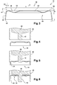
- Figures 4, 5 and 6 represent the sequence consisting in arranging the sealing member 34 in the tubular sleeve 26.
- the sealing member 34 is in rest position, as it is represented in figure 3 , and it faces the end of the sleeve 26 wherein are already arranged the actuator member 26 and the pusher member 30.
- the sealing member 34 is arranged in place inside the sleeve 26.
- the sealing member 34 has been axially X upwardly pushed and press-fitted inside the sleeve 26 with sufficient force to elastically deform the conical shape of the peripheral wall 38 which resiliently narrows to match the cylindrical shape of the sleeve 26.
- the necessary force to press fit the sealing member 34 may not exceed few hundreds Newton's, the objective of the press fit being to ensure a continuous circumferential contact between the peripheral wall and the internal face of the sleeve, regardless of the manufacturing tolerance.
- the external edge 62 of the sealing member 34 may be fixed, for instance by laser welding inside the sleeve 26. Other known means of fixation may be utilized, such as brazing or even gluing.
- the shape of the sealing member 34 provides resilient characteristics, meaning that, should the sealing member 34 be disengaged from the sleeve 26 it would almost take back its rest shape with a conical peripheral wall 38, some permanent plastic deformation may still be remaining.
- the dimensions of the sealing member 34 are chosen according to the following criteria: D ⁇ T 4 ⁇ H ⁇ D ⁇ T where 0.05 mm ⁇ T ⁇ 0.3 mm H being the height of the waviness measured along the main axis X, D being the larger diameter of the peripheral wall, or diameter of the external edge and, T being the thickness of the walls of the sealing member.
- the height H of the waviness has to be comprised between 0.25 mm and 1 mm.
- Figure 7 depicts a sealing member which has a reduced total height and, to achieve similar press fit, the angle A2 of the cone is larger.
- the sealing member 34 of figure 8 is thicker and the waviness height H is also reduced.
- the sealing member 34 of figure 9 is thinner and the height H remains fairly small so, in order to accommodate the deformation the conical angle A2 is very small, leading to minor deformation when engaging the sealing member in the sleeve.
- the sealing member 34 of figure 10 is also thin and the rounded outer area 60 has a large radius enabling a noticeable axial raise of the bottom wall 36 when engaging the member in the sleeve 26, the conical angle A2 of the peripheral wall being slightly larger than on the embodiment of figure 9 .
- the sealing member 34 of figure 11 is also quite thin and the bottom wall 36 presents two concentric waves 58.
- the rounded outer area 60 has a small radius and the conical angle A2 is more important than in the previous embodiment.
- the summit of the waves, of the rounded area and of the border 56 of the central hole are coplanar, the height of the central wave being smaller than the height of the external wave.
- the sealing member 34 of figure 12 is also provided with two concentric waves.
- the thickness T is slightly more important and the conical angle A2 remains similar.
Landscapes
- Engineering & Computer Science (AREA)
- Physics & Mathematics (AREA)
- Fluid Mechanics (AREA)
- Chemical & Material Sciences (AREA)
- Combustion & Propulsion (AREA)
- Mechanical Engineering (AREA)
- General Engineering & Computer Science (AREA)
- Fuel-Injection Apparatus (AREA)
Abstract
Description
- The present invention relates to a resilient sealing member adapted to protect a servo actuator of a fuel injector.
- In servo fuel injector, an actuator member, either piezo or magneto restrictive, cooperates with a control valve to indirectly enable or forbid fuel injection.
- The actuator member is provided with a pusher member having a central shaft projection enabling cooperation with the control valve. The actuator and pusher members are arranged in a cylindrical tubular sleeve provided at an extremity with a resilient sealing member, the pusher member being in abutment against the inner face of the sealing member, the shaft projection extending through a central hole provided in said sealing member.
- Protection of the actuator member against fuel contact is ensured by the sealing member since the peripheral area is in intimate contact with the inner face of the sleeve and the border of the central hole is in contact with the pusher member.
- The actuator member operates at high frequency where it alternatively expends and retracts. The sealing member slightly resiliently deflects to accommodate said variations and, the repeated deflections induce fatigue stresses that may damage the sealing member.
- Accordingly, it is an object of the present invention to resolve the above mentioned problems in providing a sealing member adapted to be arranged inside a tubular sleeve extending along a main axis and in which is arranged a servo actuator. The sealing member is a metallic pan-shaped resilient membrane with a centrally holed bottom wall perpendicular to said main axis.
- The sealing member further comprises a conical peripheral wall adapted to inwardly deform in order to be press fitted with interference inside the tubular sleeve. The bottom wall is non-planar and, the peripheral wall and the bottom wall merge in a toroid rounded outer area.
- Also, the bottom wall is provided with at least a circular waviness (58) concentric to the central hole, the waviness providing resilient characteristics to said bottom wall.
- The conical angle of the peripheral wall is smaller than 20 degrees.
- The axial section of said toroid rounded outer area share a first tangent with the peripheral wall and a second tangent with the bottom face, the first and second tangents being at an angle inferior to 90 degrees.
- The height measured in the axial direction of the waviness of the non-planar bottom wall is calculated as per the formula:

- D is the larger diameter of the peripheral wall and,
- T is the thickness of the walls of the sealing member, T being inferior to 0.5 mm.
- Height of the waviness is preferably equal to:

- The invention also extends to a servo actuator assembly of a servo injector, the actuator assembly comprising a cylindrical actuator member inserted in a tubular sleeve provided at an extremity with a sealing member as described above, the actuator member abutting on a face of the bottom wall of the sealing member and, a shaft member integral to the actuator member projecting through the central hole of the bottom wall.
- The invention also extends to a servo injector provided with an actuator assembly as described above. The actuator member can be a piezo or a magneto restrictive actuator.
- The present invention is now described by way of example with reference to the accompanying drawings in which:
-
Figure 1 is an erection view of a fuel injector, a partial cut-out in the view enabling to present an internal area where an extremity of the actuator of the injector cooperates with the stem of a control valve. -
Figure 2 is a magnified view of the cut-out offigure 1 enabling a more distinctive appreciation of the extremity of the actuator arranged in a tubular sleeve closed by a sealing member, a pusher extension cooperating with the stem of the valve. -
Figure 3 is an axial section of the sealing member offigure 2 . -
Figures 4, 5 and 6 are sequential views presenting the engagement of the sealing member offigure 3 in the tubular sleeve where the actuator is arranged. -
Figures 7 to 12 are distinct embodiments of sealing member as per the invention. - In reference to
figure 1 is represented aservo injector 10 generally extending along a main axis X and comprising from top to bottom in the arbitrary and non-limiting orientation of the figure aservo assembly 12, acontrol valve assembly 14 and anozzle assembly 16. - The
servo assembly 12 has abody 18 provided with an axial X bore 20 opening in thebottom face 22 of thebody 18 and in which is arranged aactuator assembly 24 comprising atubular sleeve 26 enclosing anactuator member 28, piezoelectric or magneto restrictive for instance, and apusher member 30, easier to see onfigure 2 . In the upper part, non-represented, theactuator member 28 comprises a head member and electrical wires extending between theactuator member 28 and aconnector 32 arranged on the top of theservo assembly 12. At the bottom end of thesleeve 26 is arranged aresilient sealing member 34 that is a pan-shaped resilient membrane, represented up-side-down and having abottom wall 36 substantially transverse to the main axis X and aperipheral wall 38 in contact with the inner face of thesleeve 26. Thebottom wall 36 is provided with acentral hole 40 to enable amale shaft member 42 integral to thepusher member 30 to project through saidhole 40 in order to cooperate with avalve 44 comprised in thecontrol valve assembly 14. Thepusher member 30 is in uninterrupted sealing contact against theupper face 46 of thebottom wall 36 and, theperipheral wall 38 is in uninterrupted sealing contact with theinner face 48 of thesleeve 26 so that fuel cannot enter thesleeve 30 and be in contact with theactuator member 28. - Throughout the
injector 10, ahigh pressure channel 50 extends from aninlet 52 arranged at the top of theactuator assembly 12, to sprayholes 54 arranged in the tip of thenozzle assembly 16. - In operation, an external control unit not represented energizes the
actuator member 28 which alternatively axially expends or retracts, opening or closing thevalve 44 and indirectly a needle valve not represented that enables or forbids fuel injection through thespray holes 54. - A first embodiment of the sealing
member 34 is now described in reference tofigure 3 , the sealingmember 34 being an integral part formed by deep drawing, or other forming processes, of a metal sheet of thickness T. Steel, such as spring steel, is typically utilize because of their known high mechanical fatigue resistance but other materials may be appropriate as well, said other materials requiring adequate forming processes. The sealingmember 34 is axisymmetric and it comprises thebottom wall 36 provided with thecentral hole 40 and theperipheral wall 38. Onfigure 3 the sealingmember 34 is represented in a stand-alone rest position, outside thesleeve 26 and, from theborder 56 of thecentral hole 40, thebottom wall 36 radially transversely extends forming concentriccircular waviness 58 having a height H measured along the main axis X. Outwardly thebottom wall 36 merges tangentially in anouter area 60 rounded as per a toroid extending to a distal end, also tangentially merging with theperipheral wall 38. The tangents on both side of the roundedouter area 60 generally make an obtuse angle A1. As visible on the figure, theperipheral wall 38 has fairly steep conical shape with an angle A2 smaller than 30 degrees; a preferred angle would be smaller than 20 degrees. Good results have been obtained with angles smaller than 10 degrees. Theperipheral wall 38 extends and widens toward an externalcircular edge 62 having a diameter D. -
Figures 4, 5 and 6 represent the sequence consisting in arranging the sealingmember 34 in thetubular sleeve 26. - In
figure 4 , thesealing member 34 is in rest position, as it is represented infigure 3 , and it faces the end of thesleeve 26 wherein are already arranged theactuator member 26 and thepusher member 30. - In
figure 5 , thesealing member 34, still in rest position, is presented to the sleeve, theshaft 42 of the pusher member initiates engagement in thecentral hole 40 and, as visible on the figure, only the bottom wall and the roundedouter area 60 can freely engage in thesleeve 26 while theperipheral wall 38 cannot has it widens to a larger section than thesleeve 26. - In
figure 6 , the sealingmember 34 is arranged in place inside thesleeve 26. The sealingmember 34 has been axially X upwardly pushed and press-fitted inside thesleeve 26 with sufficient force to elastically deform the conical shape of theperipheral wall 38 which resiliently narrows to match the cylindrical shape of thesleeve 26. As an illustration, the necessary force to press fit the sealingmember 34 may not exceed few hundreds Newton's, the objective of the press fit being to ensure a continuous circumferential contact between the peripheral wall and the internal face of the sleeve, regardless of the manufacturing tolerance. - Deforming and narrowing the external portion of the peripheral wall generates internal stresses in the
rounded area 60 forcing said rounded area to slightly pivots about itself moving upward thebottom wall 36 in further sealing abutment against the pusher member. - Not further detailed, once in place, to secure the sealing properties, the
external edge 62 of the sealingmember 34 may be fixed, for instance by laser welding inside thesleeve 26. Other known means of fixation may be utilized, such as brazing or even gluing. The shape of the sealingmember 34 provides resilient characteristics, meaning that, should the sealingmember 34 be disengaged from thesleeve 26 it would almost take back its rest shape with a conicalperipheral wall 38, some permanent plastic deformation may still be remaining. To provide said characteristics, the dimensions of thesealing member 34 are chosen according to the following criteria:
H being the height of the waviness measured along the main axis X, D being the larger diameter of the peripheral wall, or diameter of the external edge and, T being the thickness of the walls of the sealing member. - As an illustration example, when thickness T is 0.1 mm and external edge diameter D is 10 mm then, the height H of the waviness has to be comprised between 0.25 mm and 1 mm.
- In reference to
figures 7 to 12 are presented for non-limiting illustration purposes different sealingmembers 36 matching the above criteria. -
Figure 7 depicts a sealing member which has a reduced total height and, to achieve similar press fit, the angle A2 of the cone is larger. - The sealing
member 34 offigure 8 is thicker and the waviness height H is also reduced. - The sealing
member 34 offigure 9 is thinner and the height H remains fairly small so, in order to accommodate the deformation the conical angle A2 is very small, leading to minor deformation when engaging the sealing member in the sleeve. - The sealing
member 34 offigure 10 is also thin and the roundedouter area 60 has a large radius enabling a noticeable axial raise of thebottom wall 36 when engaging the member in thesleeve 26, the conical angle A2 of the peripheral wall being slightly larger than on the embodiment offigure 9 . - The sealing
member 34 offigure 11 is also quite thin and thebottom wall 36 presents twoconcentric waves 58. The roundedouter area 60 has a small radius and the conical angle A2 is more important than in the previous embodiment. The summit of the waves, of the rounded area and of theborder 56 of the central hole are coplanar, the height of the central wave being smaller than the height of the external wave. - The sealing
member 34 offigure 12 is also provided with two concentric waves. The thickness T is slightly more important and the conical angle A2 remains similar. -
- X
- main axis
- T
- thickness of the metal sheet of the sealing member
- H
- height of the waviness
- D
- diameter of the extremal edge of the sealing member
- A1
- angle between the tangents on both sides of the outer area
- A2
- angle of the cone
- 10
- injector
- 12
- servo assembly
- 14
- control valve assembly
- 16
- nozzle assembly
- 18
- body of the servo assembly
- 20
- bore
- 22
- bottom face of the body
- 24
- actuator assembly
- 26
- tubular sleeve
- 28
- actuator member
- 30
- pusher member
- 32
- connector
- 34
- sealing member
- 36
- bottom wall
- 38
- peripheral wall
- 40
- central hole
- 42
- shaft member of the pusher member
- 44
- valve
- 46
- upper face of the bottom wall
- 48
- inner face of the sleeve
- 50
- high pressure channel
- 52
- inlet
- 54
- spray holes
- 56
- border of the central hole
- 58
- waviness
- 60
- outer area
- 62
- external edge
Claims (9)
the sealing member (34) further comprises a conical peripheral wall (38) adapted to inwardly deform in order to be press fitted with interference inside the tubular sleeve (26),
the bottom wall (36) is non-planar and,
the peripheral wall (38) and the bottom wall (36) merge in a toroid rounded outer area (60).

Applications Claiming Priority (1)
| Application Number | Priority Date | Filing Date | Title |
|---|---|---|---|
| GBGB1509473.3A GB201509473D0 (en) | 2015-06-02 | 2015-06-02 | Sealing membrane for piezo actuator |
Publications (1)
| Publication Number | Publication Date |
|---|---|
| EP3101262A1 true EP3101262A1 (en) | 2016-12-07 |
Family
ID=53677594
Family Applications (1)
| Application Number | Title | Priority Date | Filing Date |
|---|---|---|---|
| EP16171591.7A Withdrawn EP3101262A1 (en) | 2015-06-02 | 2016-05-26 | Sealing membrane for piezo actuator |
Country Status (2)
| Country | Link |
|---|---|
| EP (1) | EP3101262A1 (en) |
| GB (1) | GB201509473D0 (en) |
Citations (6)
| Publication number | Priority date | Publication date | Assignee | Title |
|---|---|---|---|---|
| DE19921242C1 (en) * | 1999-05-07 | 2000-10-26 | Siemens Ag | Method of positioning control drive in common rail fuel injector for motor vehicle internal combustion engine |
| DE10016247A1 (en) * | 2000-03-31 | 2001-10-04 | Siemens Ag | Fuel injection valve with sealing membrane |
| DE10233100A1 (en) * | 2002-07-20 | 2004-01-29 | Robert Bosch Gmbh | Piezoelectric actuator module and method for assembling a piezoelectric actuator module |
| JP2009057939A (en) * | 2007-09-03 | 2009-03-19 | Denso Corp | Piezoelectric element sealing structure |
| WO2013011124A1 (en) * | 2011-07-20 | 2013-01-24 | Reinz-Dichtungs-Gmbh | Seal system |
| WO2016074888A1 (en) * | 2014-11-11 | 2016-05-19 | Delphi International Operations Luxembourg S.À R.L. | Hydraulic lash adjuster arranged in a servo injector |
-
2015
- 2015-06-02 GB GBGB1509473.3A patent/GB201509473D0/en not_active Ceased
-
2016
- 2016-05-26 EP EP16171591.7A patent/EP3101262A1/en not_active Withdrawn
Patent Citations (6)
| Publication number | Priority date | Publication date | Assignee | Title |
|---|---|---|---|---|
| DE19921242C1 (en) * | 1999-05-07 | 2000-10-26 | Siemens Ag | Method of positioning control drive in common rail fuel injector for motor vehicle internal combustion engine |
| DE10016247A1 (en) * | 2000-03-31 | 2001-10-04 | Siemens Ag | Fuel injection valve with sealing membrane |
| DE10233100A1 (en) * | 2002-07-20 | 2004-01-29 | Robert Bosch Gmbh | Piezoelectric actuator module and method for assembling a piezoelectric actuator module |
| JP2009057939A (en) * | 2007-09-03 | 2009-03-19 | Denso Corp | Piezoelectric element sealing structure |
| WO2013011124A1 (en) * | 2011-07-20 | 2013-01-24 | Reinz-Dichtungs-Gmbh | Seal system |
| WO2016074888A1 (en) * | 2014-11-11 | 2016-05-19 | Delphi International Operations Luxembourg S.À R.L. | Hydraulic lash adjuster arranged in a servo injector |
Also Published As
| Publication number | Publication date |
|---|---|
| GB201509473D0 (en) | 2015-07-15 |
Similar Documents
| Publication | Publication Date | Title |
|---|---|---|
| JP2010242575A (en) | Fuel injection valve | |
| US11458523B2 (en) | Plug assembly for use in a vehicle | |
| JP5831510B2 (en) | Fuel injection valve and fuel injection valve mounting method | |
| US11242833B2 (en) | Injector cup, spring clip, and fluid injection assembly | |
| EP3101262A1 (en) | Sealing membrane for piezo actuator | |
| JP2016522013A (en) | Improved spray head | |
| EP3431747B1 (en) | Control valve arrangement | |
| EP3284945B1 (en) | Gasoline direct injection rail | |
| EP3006721A1 (en) | Electromagnetic fuel injection valve | |
| US10302054B2 (en) | Fuel injection valve | |
| US9771911B2 (en) | Fuel injection valve | |
| EP2706221A1 (en) | Valve assembly for a fuel injector and fuel injector | |
| KR20180095905A (en) | Valve assembly and fluid injection valve | |
| US10408156B2 (en) | Control device | |
| JP5983847B2 (en) | Fuel injection valve | |
| JP5722816B2 (en) | Connecting joints, alignment members and segments | |
| US9341154B2 (en) | Valve assembly for a fuel injector and fuel injector | |
| EP3009660B1 (en) | Valve assembly with a guiding element and fluid injector | |
| JP4824120B2 (en) | Spacer | |
| JP4560065B2 (en) | Spacer | |
| JP6260316B2 (en) | Fuel injection valve | |
| JP5723671B2 (en) | Fuel injection valve | |
| JP2011185183A (en) | Orifice processing method | |
| JP2019044940A (en) | Blind rivet and encapsulation structure | |
| EP3359802A1 (en) | Locating member |
Legal Events
| Date | Code | Title | Description |
|---|---|---|---|
| PUAI | Public reference made under article 153(3) epc to a published international application that has entered the european phase |
Free format text: ORIGINAL CODE: 0009012 |
|
| AK | Designated contracting states |
Kind code of ref document: A1 Designated state(s): AL AT BE BG CH CY CZ DE DK EE ES FI FR GB GR HR HU IE IS IT LI LT LU LV MC MK MT NL NO PL PT RO RS SE SI SK SM TR |
|
| AX | Request for extension of the european patent |
Extension state: BA ME |
|
| 17P | Request for examination filed |
Effective date: 20170607 |
|
| RBV | Designated contracting states (corrected) |
Designated state(s): AL AT BE BG CH CY CZ DE DK EE ES FI FR GB GR HR HU IE IS IT LI LT LU LV MC MK MT NL NO PL PT RO RS SE SI SK SM TR |
|
| 17Q | First examination report despatched |
Effective date: 20180917 |
|
| STAA | Information on the status of an ep patent application or granted ep patent |
Free format text: STATUS: THE APPLICATION IS DEEMED TO BE WITHDRAWN |
|
| 18D | Application deemed to be withdrawn |
Effective date: 20190129 |