EP3100952A1 - Armrest structure and aircraft seat thereof - Google Patents
Armrest structure and aircraft seat thereof Download PDFInfo
- Publication number
- EP3100952A1 EP3100952A1 EP15184499.0A EP15184499A EP3100952A1 EP 3100952 A1 EP3100952 A1 EP 3100952A1 EP 15184499 A EP15184499 A EP 15184499A EP 3100952 A1 EP3100952 A1 EP 3100952A1
- Authority
- EP
- European Patent Office
- Prior art keywords
- supporting
- arm body
- supporting board
- aircraft
- aircraft seat
- Prior art date
- Legal status (The legal status is an assumption and is not a legal conclusion. Google has not performed a legal analysis and makes no representation as to the accuracy of the status listed.)
- Withdrawn
Links
- 238000000034 method Methods 0.000 description 4
- 238000005192 partition Methods 0.000 description 3
- 238000010420 art technique Methods 0.000 description 1
- 238000005352 clarification Methods 0.000 description 1
Images


Classifications
-
- B—PERFORMING OPERATIONS; TRANSPORTING
- B64—AIRCRAFT; AVIATION; COSMONAUTICS
- B64D—EQUIPMENT FOR FITTING IN OR TO AIRCRAFT; FLIGHT SUITS; PARACHUTES; ARRANGEMENTS OR MOUNTING OF POWER PLANTS OR PROPULSION TRANSMISSIONS IN AIRCRAFT
- B64D11/00—Passenger or crew accommodation; Flight-deck installations not otherwise provided for
- B64D11/06—Arrangements of seats, or adaptations or details specially adapted for aircraft seats
- B64D11/0639—Arrangements of seats, or adaptations or details specially adapted for aircraft seats with features for adjustment or converting of seats
- B64D11/0644—Adjustable arm rests
-
- B—PERFORMING OPERATIONS; TRANSPORTING
- B60—VEHICLES IN GENERAL
- B60N—SEATS SPECIALLY ADAPTED FOR VEHICLES; VEHICLE PASSENGER ACCOMMODATION NOT OTHERWISE PROVIDED FOR
- B60N2/00—Seats specially adapted for vehicles; Arrangement or mounting of seats in vehicles
- B60N2/75—Arm-rests
-
- B—PERFORMING OPERATIONS; TRANSPORTING
- B60—VEHICLES IN GENERAL
- B60N—SEATS SPECIALLY ADAPTED FOR VEHICLES; VEHICLE PASSENGER ACCOMMODATION NOT OTHERWISE PROVIDED FOR
- B60N2/00—Seats specially adapted for vehicles; Arrangement or mounting of seats in vehicles
- B60N2/75—Arm-rests
- B60N2/753—Arm-rests movable to an inoperative position
-
- B—PERFORMING OPERATIONS; TRANSPORTING
- B64—AIRCRAFT; AVIATION; COSMONAUTICS
- B64D—EQUIPMENT FOR FITTING IN OR TO AIRCRAFT; FLIGHT SUITS; PARACHUTES; ARRANGEMENTS OR MOUNTING OF POWER PLANTS OR PROPULSION TRANSMISSIONS IN AIRCRAFT
- B64D11/00—Passenger or crew accommodation; Flight-deck installations not otherwise provided for
- B64D11/06—Arrangements of seats, or adaptations or details specially adapted for aircraft seats
- B64D11/0646—Seats characterised by special features of stationary arms, foot or head rests
Definitions
- the present invention relates to a technical field of seat, and especially relates to an arm structure and an aircraft seat assembly thereof for aircraft and other communications and transportation vehicles.
- a prior seat arrangement on an aircraft is that a plurality of aircraft seats are set adjacently with each other.
- window seats are arranged in a group of two seats or three seats set adjacently with each other, and center seats in center region are arranged in a group of four seats, five seats or more set adjacently with each other.
- passengers seat on each two adjacent aircraft seats may share a common arm, which is set between the two adjacent aircraft seats.
- arms of the two adjacent aircraft seats are very near, accordingly hands of passengers may touch with each other. The touching problem between passengers is seriously and bothers passengers all the time very much.
- the inventor(s) of the present invention meditate and design an arm structure and an aircraft seat assembly thereof for improving the problems of existing technique and increasing the industrial applications and embodiments.
- the object of the present invention is to provide an arm structure and an aircraft seat assembly thereof, which can improve the problems resulted from prior art technique.
- an arm structure in accordance with the object of the present invention, includes an arm body and a supporting board.
- the arm body is set between two adjacent aircraft seats.
- the supporting board is shaped corresponding to the arm body and pivotally connected to two sides of the arm body, wherein the supporting board has a first position and a second position. When the two supporting boards are in the first position, the two supporting boards integrated with the arm body to form an arm. When the two supporting boards are in the second position, the two supporting boards are perpendicular to the arm body, for supporting hands of passengers seated on the two adjacent aircraft seats.
- the arm body may include two recess portions, wherein the two supporting boards are set within the recess portions.
- an end of the supporting board and a side of the supporting board near the arm body are pivotally set within the recess portion, and the side of the supporting board is near a seat cushion of the aircraft seat.
- the supporting board can be turned to the seat cushion of the aircraft seat, so that the two supporting boards can be rotated from the first position into the second position.
- the arm body may include two recess portions, wherein the two supporting boards are set within the recess portions.
- the width of the supporting board is less than the width of the arm body, an end of the supporting board and a side of the supporting board near the arm body are pivotally set within the recess portion, and the side of the supporting board is opposite to a seat cushion of the aircraft seat.
- the supporting board can be turned corresponding to the seat cushion of the aircraft seat, so that the two supporting boards can be rotated from the first position into the second position.
- an end of the supporting board and a side of the supporting board near the arm body are pivotally set within the recess portion, and the side of the supporting board is opposite to a seat cushion of the aircraft seat.
- the supporting board can be turned corresponding to the seat cushion of the aircraft seat, so that the two supporting boards can be rotated from the first position into the second position, where the two supporting boards and the arm body are integrated in a reverse T-shape.
- an aircraft seat assembly is further provided.
- the aircraft seat assembly includes a plurality of aircraft seats and at least one arm structure.
- the aircraft seats are set adjacently with each other.
- the arm structure includes an arm body and two supporting boards.
- the arm body is set between the aircraft seats.
- the two supporting boards are shaped corresponding to the arm body, and are pivotally connected to two sides of the arm body respectively, wherein each of the two supporting boards has a first position and a second position. When the two supporting boards are in the first position, the two supporting boards integrated with the arm body to form an arm. When the two supporting boards are in the second position, the two supporting boards are perpendicular to the arm body, for supporting hands of passengers seated on the aircraft seats.
- the arm body may include two recess portions, and the two supporting boards are set within the recess portions.
- an end of the supporting board and a side of the supporting board near the arm body can be pivotally set within the recess portion, and the side of the supporting board is near a seat cushion of the aircraft seat.
- the supporting board can be turned to the seat cushion of the aircraft seat, so that the two supporting boards are rotated from the first position into the second position.
- the width of the supporting board can be less than the width of the arm body, an end of the supporting board and a side of the supporting board near the arm body are pivotally set within the recess portion, and the side of the supporting board is opposite to a seat cushion of the aircraft seat.
- the supporting board can be turned corresponding to the seat cushion of the aircraft seat, so that the two supporting boards are rotated from the first position into the second position.
- an end of the supporting board and a side of the supporting board near the arm body are pivotally set within the recess portion, and the side of the supporting board is opposite to a seat cushion of the aircraft seat.
- the supporting board can be turned corresponding to the seat cushion of the aircraft seat, so that the two supporting boards can be rotated from the first position into the second position, where the two supporting boards and the arm body are integrated in a reverse T-shape.
- the two supporting boards when the two supporting boards are rotated to the first position, the two supporting boards can be integrated with the arm body to form an arm, so that the outlook appearance of the arm structure is smoothly and not suddenly such that the aesthetic of the arm structure is accordingly improved. Furthermore, when the two supporting boards are in the second position, the two supporting boards are perpendicular to the arm body, for supporting hands of passengers seated on the aircraft seats. Therefore, the hands of the passengers seated on the adjacent aircraft seats can be prevented from touching each other, and the problems bothered the passengers can be resolved.
- FIGs. 1 and 2 they illustrate a first schematic and a second schematic of a first embodiment of an aircraft seat assembly according to the present invention.
- the aircraft seat assembly 100 includes an arm structure 10 of the present invention, which is used for passengers putting their hands appropriately.
- the aircraft seat assembly 100 includes an arm structure 10 and an aircraft seat 20.
- the amount of the aircraft seat 20 may be two, three or more, and the amount of the arm structure 10 may be corresponding one, two or more.
- the present invention uses two aircraft seat 20 and one arm structure 10 as an example. However, it cannot be used for limiting the present invention
- the two aircraft seats 20 are located adjacently.
- the arm structure 10 includes an arm body 101 and two supporting boards 102.
- the arm structure 10 is set between the two adjacent aircraft seats 20.
- the two supporting boards 102 are shaped corresponding to the arm body 101, and pivotally connected to two sides of the arm body 101 respectively.
- Each of the two supporting boards 102 has a first position A and a second position B.
- the two supporting boards 102 when the two supporting boards 102 are in the first position A, the two supporting boards 102 are integrated with the arm body 101 harmoniously to form an arm in normal shape. As shown in Fig. 2 , when the two supporting boards 102 are in the second position B, the two supporting boards 102 are perpendicular to the arm body, for supporting hands of passengers seated on the two aircraft seats 20.
- the arm body 101 is in a T shape from a top view. That is, the arm body 101 includes two recess portions from a top view, wherein the two supporting boards are set within the recess portions. Therefore, when the two supporting boards 102 are in the first position A, the two supporting boards 102 can be filled in the recess portions of the arm body harmoniously, and the two supporting boards 102 can accordingly be integrated with the arm body 101 to form an arm not suddenly.
- an end of the supporting board 102 and a side of the supporting board 102 near the arm body 101 are pivotally set within the recess portion 1011, and the side of the supporting board 102 is near seat cushion 201 of the aircraft seat 20. Therefore, the passengers seated on the aircraft seat 20 can turn the supporting board 102 to the direction of the seat cushion 201 of the aircraft seat 20, so that the supporting board 102 is rotated from the first position A into the second position B. Thus, the passengers seated on the aircraft seat 20 can put their hands on the supporting board 102 comfortably.
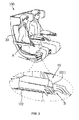
- FIG. 3 it illustrates a third schematic of the first embodiment of the aircraft seat assembly according to the present invention.
- the two supporting boards 102 and the arm body 101 are integrated in a reverse T-shape from a cross-sectional view at an end of the arm body 101. Therefore, the passengers seated on the aircraft seat 20 and on both sides of the arm structure 10 can put their hands on the supporting board 102 respectively, and the arm body 101 can naturally be a partition board for preventing hands of the passengers from touching each other.
- the problems of un-purposely touching hands which bothered the passengers can be resolved.
- the techniques used for the supporting board 102 pivotally set within the recess portion 1011 can be any ones known by skilled in the art.
- it can be a method of using a hinge for prior flip electronics devices or using a cylinder lodging in a circular hole.
- an engaging part is used to preventing the supporting board 102 from suddenly or unexpectedly rotating between the first position A and the second position B.
- the engaging part can work by interference between two parts or engagement.
- the engaging part such as a protrusion
- a pit is set on the walls of the supporting board 102, so that the supporting board 102 can be engaged in the first position A when the protrusion engages the pit.
- the engaging part such as a hook
- the engaging part can be set on the walls of the recess portion 1011 and a groove is set on the walls of the supporting board 102 corresponding to the hook, so that the supporting board 102 can be engaged in the first position A when the hook engages the groove.
- FIGs. 4 and 5 they illustrate a first schematic and a second schematic of a second embodiment of an aircraft seat assembly according to the present invention.
- some components are the same and need not described anymore.
- the major difference between the second embodiment and the first embodiment is that the supporting board 102 is rotated from the first position A into the second position B.
- the width of the supporting board 102 is less than the width of the arm body 101.
- an end of the supporting board 102 and a side of the supporting board 102 near the arm body 102 are pivotally set within the recess portion 1011, wherein the side of the supporting board 102 is opposite to the seat cushion 201 of the aircraft seat 20.
- the passengers seated on the aircraft seat 20 can rotate the supporting board 102 forward or backward with respect to the seat cushion 201 of the aircraft seat 20, so that the supporting board 102 can be rotated between the first position A and the second position B.
- the two supporting boards 102 and the arm body 101 are integrated in substantially a reverse T-shape from a cross-sectional view at an end of the arm body 101.
- the passengers seated on the aircraft seat 20 and on both sides of the arm structure 10 can put their hands on the supporting board 102 respectively, and the arm body 101 can naturally be a partition board for preventing hands of the passengers from touching each other.
- the problems of un-purposely touching hands which bothered the passengers can be resolved.
- FIG. 6 it illustrates a schematic of a third embodiment of an aircraft seat assembly according to the present invention.
- the third embodiment is that the supporting board 102 is rotated from the first position A into the second position B.
- the difference between the third embodiment and the second embodiment is that the two supporting boards 102 and the arm body 101 are integrated in a T-shape from a cross-sectional view at an end of the arm body 101, after the supporting board 102 rotating from the first position A into the second position B.
- the width of the supporting board 102 can correspond to or equal to the width of the arm body 101.
- an end of the supporting board 102 and a side of the supporting board 102 near the arm body 101 are pivotally set within the recess portion 1011, and the side of the supporting board 102 is opposite to the seat cushion 201 of the aircraft seat 20.
- the passengers seated on the aircraft seat 20 can turn the supporting board 102 to or back to the seat cushion 201 of the aircraft seat 20, so that the supporting board 102 can be rotated from the first position A into the second position B.
- the two supporting boards 102 and the arm body 101 are integrated in substantially a T-shape from a cross-sectional view at an end of the arm body 101. That is, the turned supporting board 102 on the second position B will be on the same plane with the top surface of the arm structure 10.
- the passengers seated on the aircraft seat 20 and on both sides of the arm structure 10 can put their hands on the supporting board 102 respectively, and the arm body 101 can naturally be a partition board for preventing hands of the passengers from touching each other.
- the problems of un-purposely touching hands which bothered the passengers can be resolved.
Abstract
Description
- This application claims priority from
Taiwan Patent Application No. 104118051, filed on June 04, 2015 - The present invention relates to a technical field of seat, and especially relates to an arm structure and an aircraft seat assembly thereof for aircraft and other communications and transportation vehicles.
- A prior seat arrangement on an aircraft is that a plurality of aircraft seats are set adjacently with each other. For example, window seats are arranged in a group of two seats or three seats set adjacently with each other, and center seats in center region are arranged in a group of four seats, five seats or more set adjacently with each other. In the above-mentioned seat arrangement, passengers seat on each two adjacent aircraft seats may share a common arm, which is set between the two adjacent aircraft seats. Or, arms of the two adjacent aircraft seats are very near, accordingly hands of passengers may touch with each other. The touching problem between passengers is seriously and bothers passengers all the time very much.
- Thus, the inventor(s) of the present invention meditate and design an arm structure and an aircraft seat assembly thereof for improving the problems of existing technique and increasing the industrial applications and embodiments.
- For the foregoing prior art problems, the object of the present invention is to provide an arm structure and an aircraft seat assembly thereof, which can improve the problems resulted from prior art technique.
- In accordance with the object of the present invention, an arm structure is provided. The arm structure includes an arm body and a supporting board. The arm body is set between two adjacent aircraft seats. The supporting board is shaped corresponding to the arm body and pivotally connected to two sides of the arm body, wherein the supporting board has a first position and a second position. When the two supporting boards are in the first position, the two supporting boards integrated with the arm body to form an arm. When the two supporting boards are in the second position, the two supporting boards are perpendicular to the arm body, for supporting hands of passengers seated on the two adjacent aircraft seats.
- In accordance with the preferred embodiments, the arm body may include two recess portions, wherein the two supporting boards are set within the recess portions.
- In accordance with the preferred embodiments, an end of the supporting board and a side of the supporting board near the arm body are pivotally set within the recess portion, and the side of the supporting board is near a seat cushion of the aircraft seat.
- In accordance with the preferred embodiments, the supporting board can be turned to the seat cushion of the aircraft seat, so that the two supporting boards can be rotated from the first position into the second position.
- In accordance with the preferred embodiments, the arm body may include two recess portions, wherein the two supporting boards are set within the recess portions.
- In accordance with the preferred embodiments, the width of the supporting board is less than the width of the arm body, an end of the supporting board and a side of the supporting board near the arm body are pivotally set within the recess portion, and the side of the supporting board is opposite to a seat cushion of the aircraft seat.
- In accordance with the preferred embodiments, the supporting board can be turned corresponding to the seat cushion of the aircraft seat, so that the two supporting boards can be rotated from the first position into the second position.
- In accordance with the preferred embodiments, an end of the supporting board and a side of the supporting board near the arm body are pivotally set within the recess portion, and the side of the supporting board is opposite to a seat cushion of the aircraft seat.
- In accordance with the preferred embodiments, the supporting board can be turned corresponding to the seat cushion of the aircraft seat, so that the two supporting boards can be rotated from the first position into the second position, where the two supporting boards and the arm body are integrated in a reverse T-shape.
- In accordance with the object of the present invention, an aircraft seat assembly is further provided. The aircraft seat assembly includes a plurality of aircraft seats and at least one arm structure. The aircraft seats are set adjacently with each other. The arm structure includes an arm body and two supporting boards. The arm body is set between the aircraft seats. The two supporting boards are shaped corresponding to the arm body, and are pivotally connected to two sides of the arm body respectively, wherein each of the two supporting boards has a first position and a second position. When the two supporting boards are in the first position, the two supporting boards integrated with the arm body to form an arm. When the two supporting boards are in the second position, the two supporting boards are perpendicular to the arm body, for supporting hands of passengers seated on the aircraft seats.
- In accordance with the preferred embodiments, the arm body may include two recess portions, and the two supporting boards are set within the recess portions.
- In accordance with the preferred embodiments, an end of the supporting board and a side of the supporting board near the arm body can be pivotally set within the recess portion, and the side of the supporting board is near a seat cushion of the aircraft seat.
- In accordance with the preferred embodiments, the supporting board can be turned to the seat cushion of the aircraft seat, so that the two supporting boards are rotated from the first position into the second position.
- In accordance with the preferred embodiments, the width of the supporting board can be less than the width of the arm body, an end of the supporting board and a side of the supporting board near the arm body are pivotally set within the recess portion, and the side of the supporting board is opposite to a seat cushion of the aircraft seat.
- In accordance with the preferred embodiments, the supporting board can be turned corresponding to the seat cushion of the aircraft seat, so that the two supporting boards are rotated from the first position into the second position.
- In accordance with the preferred embodiments, an end of the supporting board and a side of the supporting board near the arm body are pivotally set within the recess portion, and the side of the supporting board is opposite to a seat cushion of the aircraft seat.
- In accordance with the preferred embodiments, the supporting board can be turned corresponding to the seat cushion of the aircraft seat, so that the two supporting boards can be rotated from the first position into the second position, where the two supporting boards and the arm body are integrated in a reverse T-shape.
- Regarding the above mentioned arm structure and aircraft seat assembly of the present invention, when the two supporting boards are rotated to the first position, the two supporting boards can be integrated with the arm body to form an arm, so that the outlook appearance of the arm structure is smoothly and not suddenly such that the aesthetic of the arm structure is accordingly improved. Furthermore, when the two supporting boards are in the second position, the two supporting boards are perpendicular to the arm body, for supporting hands of passengers seated on the aircraft seats. Therefore, the hands of the passengers seated on the adjacent aircraft seats can be prevented from touching each other, and the problems bothered the passengers can be resolved.
- Features will become apparent to those of skill in the art by describing in detail exemplary embodiments with reference to the attached drawings in which:
-
Fig. 1 illustrates a first schematic of a first embodiment of an aircraft seat assembly according to the present invention. -
Fig. 2 illustrates a second schematic of the first embodiment of an aircraft seat assembly according to the present invention. -
Fig. 3 illustrates a third schematic of the first embodiment of an aircraft seat assembly according to the present invention. -
Fig. 4 illustrates a first schematic of a second embodiment of an aircraft seat assembly according to the present invention. -
Fig. 5 illustrates a second schematic of the second embodiment of an aircraft seat assembly according to the present invention. -
Fig. 6 illustrates a schematic of a third embodiment of an aircraft seat assembly according to the present invention. - Example embodiments are described more fully hereinafter with reference to the accompanying drawings; however, since the drawings are shown for clearly describing and supporting the specification of the present invention, they may not in real proportional scale or with precise arrangement. Therefore, they may be embodied in different forms and should not be construed as limited to the embodiments set forth herein. Rather, these embodiments are provided so that this disclosure will be thorough and complete, and will fully convey exemplary implementations to those skilled in the art.
- Referring to the related drawings, the following description will disclose some example embodiments of an arm structure and an aircraft seat assembly of the present invention. For clarification and understanding, like reference numerals refer to like elements throughout.
- Referring to
Figs. 1 and2 , they illustrate a first schematic and a second schematic of a first embodiment of an aircraft seat assembly according to the present invention. Theaircraft seat assembly 100 includes anarm structure 10 of the present invention, which is used for passengers putting their hands appropriately. - As shown in
Figs. 1 and2 , theaircraft seat assembly 100 includes anarm structure 10 and anaircraft seat 20. The amount of theaircraft seat 20 may be two, three or more, and the amount of thearm structure 10 may be corresponding one, two or more. In this embodiment, the present invention uses twoaircraft seat 20 and onearm structure 10 as an example. However, it cannot be used for limiting the present invention - The two
aircraft seats 20 are located adjacently. Thearm structure 10 includes anarm body 101 and two supportingboards 102. Thearm structure 10 is set between the two adjacent aircraft seats 20. The two supportingboards 102 are shaped corresponding to thearm body 101, and pivotally connected to two sides of thearm body 101 respectively. Each of the two supportingboards 102 has a first position A and a second position B. - As shown in
Fig. 1 , when the two supportingboards 102 are in the first position A, the two supportingboards 102 are integrated with thearm body 101 harmoniously to form an arm in normal shape. As shown inFig. 2 , when the two supportingboards 102 are in the second position B, the two supportingboards 102 are perpendicular to the arm body, for supporting hands of passengers seated on the twoaircraft seats 20. - Furthermore, the
arm body 101 is in a T shape from a top view. That is, thearm body 101 includes two recess portions from a top view, wherein the two supporting boards are set within the recess portions. Therefore, when the two supportingboards 102 are in the first position A, the two supportingboards 102 can be filled in the recess portions of the arm body harmoniously, and the two supportingboards 102 can accordingly be integrated with thearm body 101 to form an arm not suddenly. - On the other hand, an end of the supporting
board 102 and a side of the supportingboard 102 near thearm body 101 are pivotally set within therecess portion 1011, and the side of the supportingboard 102 is nearseat cushion 201 of theaircraft seat 20. Therefore, the passengers seated on theaircraft seat 20 can turn the supportingboard 102 to the direction of theseat cushion 201 of theaircraft seat 20, so that the supportingboard 102 is rotated from the first position A into the second position B. Thus, the passengers seated on theaircraft seat 20 can put their hands on the supportingboard 102 comfortably. - Referring further to
Fig. 3 , it illustrates a third schematic of the first embodiment of the aircraft seat assembly according to the present invention. As shown inFig. 3 , when the two supportingboards 102 are in the second position B, the two supportingboards 102 and thearm body 101 are integrated in a reverse T-shape from a cross-sectional view at an end of thearm body 101. Therefore, the passengers seated on theaircraft seat 20 and on both sides of thearm structure 10 can put their hands on the supportingboard 102 respectively, and thearm body 101 can naturally be a partition board for preventing hands of the passengers from touching each other. By way of the design of the present invention, the problems of un-purposely touching hands which bothered the passengers can be resolved. - By the way, the techniques used for the supporting
board 102 pivotally set within therecess portion 1011 can be any ones known by skilled in the art. For example, it can be a method of using a hinge for prior flip electronics devices or using a cylinder lodging in a circular hole. When using the method of a cylinder lodging in a circular hole, it is preferred that an engaging part is used to preventing the supportingboard 102 from suddenly or unexpectedly rotating between the first position A and the second position B. The engaging part can work by interference between two parts or engagement. For example, the engaging part, such as a protrusion, can be set on the walls of therecess portion 1011 and a pit is set on the walls of the supportingboard 102, so that the supportingboard 102 can be engaged in the first position A when the protrusion engages the pit. Or, the engaging part, such as a hook, can be set on the walls of therecess portion 1011 and a groove is set on the walls of the supportingboard 102 corresponding to the hook, so that the supportingboard 102 can be engaged in the first position A when the hook engages the groove. - Referring to
Figs. 4 and 5 , they illustrate a first schematic and a second schematic of a second embodiment of an aircraft seat assembly according to the present invention. In this embodiment, some components are the same and need not described anymore. The major difference between the second embodiment and the first embodiment is that the supportingboard 102 is rotated from the first position A into the second position B. - Further, in accordance with the second embodiment, the width of the supporting
board 102 is less than the width of thearm body 101. In addition, an end of the supportingboard 102 and a side of the supportingboard 102 near thearm body 102 are pivotally set within therecess portion 1011, wherein the side of the supportingboard 102 is opposite to theseat cushion 201 of theaircraft seat 20. - Therefore, the passengers seated on the
aircraft seat 20 can rotate the supportingboard 102 forward or backward with respect to theseat cushion 201 of theaircraft seat 20, so that the supportingboard 102 can be rotated between the first position A and the second position B. The two supportingboards 102 and thearm body 101 are integrated in substantially a reverse T-shape from a cross-sectional view at an end of thearm body 101. The passengers seated on theaircraft seat 20 and on both sides of thearm structure 10 can put their hands on the supportingboard 102 respectively, and thearm body 101 can naturally be a partition board for preventing hands of the passengers from touching each other. By way of the design of the present invention, the problems of un-purposely touching hands which bothered the passengers can be resolved. - Referring to
Fig. 6 , it illustrates a schematic of a third embodiment of an aircraft seat assembly according to the present invention. In this embodiment, some components are the same and need not described anymore. The major difference between the third embodiment and the first embodiment is that the supportingboard 102 is rotated from the first position A into the second position B. And the difference between the third embodiment and the second embodiment is that the two supportingboards 102 and thearm body 101 are integrated in a T-shape from a cross-sectional view at an end of thearm body 101, after the supportingboard 102 rotating from the first position A into the second position B. - In this embodiment, the width of the supporting
board 102 can correspond to or equal to the width of thearm body 101. In addition, an end of the supportingboard 102 and a side of the supportingboard 102 near thearm body 101 are pivotally set within therecess portion 1011, and the side of the supportingboard 102 is opposite to theseat cushion 201 of theaircraft seat 20. - Therefore, the passengers seated on the
aircraft seat 20 can turn the supportingboard 102 to or back to theseat cushion 201 of theaircraft seat 20, so that the supportingboard 102 can be rotated from the first position A into the second position B. The two supportingboards 102 and thearm body 101 are integrated in substantially a T-shape from a cross-sectional view at an end of thearm body 101. That is, the turned supportingboard 102 on the second position B will be on the same plane with the top surface of thearm structure 10. The passengers seated on theaircraft seat 20 and on both sides of thearm structure 10 can put their hands on the supportingboard 102 respectively, and thearm body 101 can naturally be a partition board for preventing hands of the passengers from touching each other. By way of the design of the present invention, the problems of un-purposely touching hands which bothered the passengers can be resolved. - Therefore, according to the preferred embodiments of the present invention, there are extra spaces provided outside both sides of the
arm structures 10, so that the passengers seated on theaircraft seat 20 and on both sides of thearm structure 10 can put their hands on the supportingboard 102 respectively, and the extra spaces can be used for preventing hands of the passengers from touching each other. By way of the design of the present invention, the problems of un-purposely touching hands which bothered the passengers can be resolved. - Example embodiments have been disclosed herein, and although specific terms are employed, they are used and are to be interpreted in a generic and descriptive sense only and not for purpose of limitation. Accordingly, it will be understood by those of skill in the art that various changes in form and details may be made without departing from the spirit and scope of the present invention as set forth in the following claims.
Claims (16)
- An arm structure, comprising:an arm body (101) set between two adjacent aircraft seats (20); andtwo supporting boards (102), shaped corresponding to the arm body (101), and pivotally connected to two sides of the arm body (101) respectively, each of the two supporting boards (102) having a first position and a second position, when the two supporting boards (102) in the first position, the two supporting boards (102) integrated with the arm body (101) to form an arm, when the two supporting boards (102) in the second position, the two supporting boards (102) perpendicular to the arm body (101), for supporting hands of passengers seated on both the two aircraft seats (20).
- The arm structure as claimed in claim 1, wherein the arm body (101) includes two recess portions (1011), and the two supporting boards (102) are set within the recess portions (1011).
- The arm structure as claimed in claim 2, wherein an end of the supporting board (102) and a side of the supporting board (102) near the arm body (101) are pivotally set within the recess portion (1011), and the side of the supporting board (102) is near a seat cushion (201) of the aircraft seat (20).
- The arm structure as claimed in claim 3, wherein the supporting board (102) is turned to the seat cushion (201) of the aircraft seat (20), so that the two supporting boards (102) are rotated from the first position into the second position.
- The arm structure as claimed in claim 2, wherein the width of the supporting board (102) is less than the width of the arm body (101), an end of the supporting board (102) and a side of the supporting board (102) near the arm body (101) are pivotally set within the recess portion (1011), and the side of the supporting board (102) is opposite to a seat cushion (201) of the aircraft seat (20).
- The arm structure as claimed in claim 5, wherein the supporting board (102) is turned to the seat cushion (201) of the aircraft seat (20), so that the two supporting boards (102) are rotated from the first position into the second position.
- The arm structure as claimed in claim 2, wherein an end of the supporting board (102) and a side of the supporting board (102) near the arm body (101) are pivotally set within the recess portion (1011), and the side of the supporting board (102) is opposite to a seat cushion (201) of the aircraft seat (20).
- The arm structure as claimed in claim 7, wherein the supporting board (102) is turned to the seat cushion (201) of the aircraft seat (20), so that the two supporting boards (102) are rotated from the first position into the second position, where the two supporting boards (102) and the arm body (101) are integrated in a reverse T-shape.
- An aircraft seat assembly, comprising:a plurality of aircraft seats (20) set adjacently with each other; andat least one arm structure, comprising:an arm body (101) set between a plurality of aircraft seats (20); andtwo supporting boards (102), shaped corresponding to the arm body (101), and pivotally connected to two sides of the arm body (101) respectively, each of the two supporting boards (102) having a first position and a second position, when the two supporting boards (102) in the first position, the two supporting boards (102) integrated with the arm body (101) to form an arm, when the two supporting boards (102) in the second position, the two supporting boards (102) perpendicular to the arm body (101), for supporting hands of passengers seated on the aircraft seats (20).
- The aircraft seat assembly as claimed in claim 9, wherein the arm body (101) includes two recess portions (1011), and the two supporting boards (102) are set within the recess portions (1011).
- The aircraft seat assembly as claimed in claim 10, wherein an end of the supporting board (102) and a side of the supporting board (102) near the arm body (101) are pivotally set within the recess portion (1011), and the side of the supporting board (102) is near a seat cushion (201) of the aircraft seat (20).
- The aircraft seat assembly as claimed in claim 11, wherein the supporting board (102) is turned to the seat cushion (201) of the aircraft seat (20), so that the two supporting boards (102) are rotated from the first position into the second position.
- The aircraft seat assembly as claimed in claim 10, wherein the width of the supporting board (102) is less than the width of the arm body (101), an end of the supporting board (102) and a side of the supporting board (102) near the arm body (101) are pivotally set within the recess portion (1011), and the side of the supporting board (102) is opposite to a seat cushion (201) of the aircraft seat (20).
- The aircraft seat assembly as claimed in claim 13, wherein the supporting board (102) is rotated corresponding to the seat cushion (201) of the aircraft seat (20), so that the two supporting boards (102) are rotated from the first position into the second position.
- The aircraft seat assembly as claimed in claim 10, wherein an end of the supporting board (102) and a side of the supporting board (102) near the arm body (101) are pivotally set within the recess portion (1011), and the side of the supporting board (102) is opposite to a seat cushion (201) of the aircraft seat (20).
- The aircraft seat assembly as claimed in claim 15, wherein the supporting board (102) is rotated forward to the seat cushion (201) of the aircraft seat (20), so that the two supporting boards (102) are rotated from the first position into the second position, where the two supporting boards (102) and the arm body (101) are integrated in a reverse T-shape.
Applications Claiming Priority (1)
| Application Number | Priority Date | Filing Date | Title |
|---|---|---|---|
| TW104118051A TWI572527B (en) | 2015-06-04 | 2015-06-04 | Armrest structure and aircraft seat assebly thereof |
Publications (1)
| Publication Number | Publication Date |
|---|---|
| EP3100952A1 true EP3100952A1 (en) | 2016-12-07 |
Family
ID=54072759
Family Applications (1)
| Application Number | Title | Priority Date | Filing Date |
|---|---|---|---|
| EP15184499.0A Withdrawn EP3100952A1 (en) | 2015-06-04 | 2015-09-09 | Armrest structure and aircraft seat thereof |
Country Status (3)
| Country | Link |
|---|---|
| US (1) | US9828101B2 (en) |
| EP (1) | EP3100952A1 (en) |
| TW (1) | TWI572527B (en) |
Cited By (1)
| Publication number | Priority date | Publication date | Assignee | Title |
|---|---|---|---|---|
| US11312498B2 (en) * | 2020-03-13 | 2022-04-26 | The Boeing Company | Convertible armrest disposed between adjacent seats |
Families Citing this family (20)
| Publication number | Priority date | Publication date | Assignee | Title |
|---|---|---|---|---|
| USRE47872E1 (en) | 2011-07-11 | 2020-02-25 | Molon Labe Llc | Slider seat for aircraft |
| EP2899066B1 (en) * | 2014-01-28 | 2019-09-25 | Airbus Defence and Space GmbH | Armrest and seat arrangement comprising the same |
| WO2015149120A1 (en) * | 2014-03-29 | 2015-10-08 | Prism Ip Licensing Co Pty Ltd | A shared armrest |
| US10279717B2 (en) * | 2016-07-21 | 2019-05-07 | Faurecia Automotive Seating, Llc | Armrest |
| US10569881B2 (en) | 2016-10-18 | 2020-02-25 | Molon Labe, Llc | Staggered aircraft seat assembly |
| USD878784S1 (en) | 2017-09-26 | 2020-03-24 | Okamura Corporation | Chair |
| USD840701S1 (en) * | 2017-10-18 | 2019-02-19 | Molon Labe, Llc | Staggered aircraft seats |
| JP1612821S (en) * | 2017-12-11 | 2018-09-03 | ||
| USD850177S1 (en) | 2017-12-15 | 2019-06-04 | Molon Labe, Llc | Aircraft seat armrests |
| US10934002B2 (en) * | 2018-01-19 | 2021-03-02 | Ami Industries, Inc. | Aircraft passenger seat extended armrest |
| USD880881S1 (en) * | 2018-03-28 | 2020-04-14 | B/E Aerospace, Inc. | Aircraft seating unit |
| USD867775S1 (en) | 2018-04-03 | 2019-11-26 | Molon Labe, Llc | Set of multilevel aircraft seat armrests |
| USD918610S1 (en) * | 2018-08-22 | 2021-05-11 | Grammer Ag | Bus seat |
| USD942765S1 (en) * | 2018-08-22 | 2022-02-08 | Grammer Ag | Train seat |
| USD936383S1 (en) | 2019-08-01 | 2021-11-23 | Molon Labe, Llc | Staggered aircraft seat assembly |
| USD924043S1 (en) | 2019-08-22 | 2021-07-06 | Molon Labe, Llc | Aircraft wheelchair accommodating seat assembly |
| US10953777B1 (en) * | 2019-08-30 | 2021-03-23 | The Boeing Company | Extendable armrest assemblies for passenger vehicle seating |
| US20220388433A1 (en) * | 2019-10-25 | 2022-12-08 | Safran Seats Usa Llc | Passenger seat armrest with a multi-zone top surface |
| US20210339868A1 (en) * | 2020-04-30 | 2021-11-04 | Adient Aerospace, Llc | Passenger utility element and seat unit |
| US20240101259A1 (en) | 2020-12-11 | 2024-03-28 | Safran Seats Usa Llc | Non-intrusive and extendable armrest |
Citations (5)
| Publication number | Priority date | Publication date | Assignee | Title |
|---|---|---|---|---|
| JPH1075847A (en) * | 1996-09-02 | 1998-03-24 | Takano Co Ltd | Armrest of connected chairs |
| US20070085389A1 (en) * | 2004-12-21 | 2007-04-19 | Hartmut Schurg | Passenger seat, an aircraft passenger seat in particular, and a passenger seat group, an aircraft passenger seat group in particular |
| EP2698276A1 (en) * | 2012-08-16 | 2014-02-19 | Airbus (S.A.S.) | Armrest assembly |
| US20140217798A1 (en) * | 2013-02-04 | 2014-08-07 | Isaac Negusse | Armrest expansion device |
| US20150084393A1 (en) * | 2013-09-21 | 2015-03-26 | Arthur Chang | Portable Armrest Divider |
Family Cites Families (7)
| Publication number | Priority date | Publication date | Assignee | Title |
|---|---|---|---|---|
| US6793282B2 (en) * | 2002-09-10 | 2004-09-21 | B E Aerospace, Inc. | Convertible passenger seat assembly |
| US20060006704A1 (en) * | 2003-12-15 | 2006-01-12 | Be Aerospace, Inc. | Vehicle seating with storage feature |
| US7631931B2 (en) * | 2007-07-06 | 2009-12-15 | Kongsberg Automotive Ab | Dual pivoting armrest arrangement for motor vehicle |
| GB2469180B8 (en) * | 2009-03-23 | 2016-06-08 | Air New Zealand Ltd | Vehicle seating arrangement |
| DE102012012261A1 (en) * | 2012-06-22 | 2013-12-24 | Recaro Aircraft Seating Gmbh & Co. Kg | Aircraft passenger seat device, has armrest unit to be supported at seat back unit or seat bottom unit and provided to two airplane seats that are arranged next to each other and mounted to seat back frame |
| GB2514356B (en) * | 2013-05-20 | 2017-01-11 | William Mcmillan Nigel | An armrest and armrest pad |
| BR102013032476B1 (en) * | 2013-12-17 | 2021-01-05 | Embraer S.A. | seat comprising a structure for armrests |
-
2015
- 2015-06-04 TW TW104118051A patent/TWI572527B/en not_active IP Right Cessation
- 2015-09-09 EP EP15184499.0A patent/EP3100952A1/en not_active Withdrawn
- 2015-09-22 US US14/860,730 patent/US9828101B2/en active Active
Patent Citations (5)
| Publication number | Priority date | Publication date | Assignee | Title |
|---|---|---|---|---|
| JPH1075847A (en) * | 1996-09-02 | 1998-03-24 | Takano Co Ltd | Armrest of connected chairs |
| US20070085389A1 (en) * | 2004-12-21 | 2007-04-19 | Hartmut Schurg | Passenger seat, an aircraft passenger seat in particular, and a passenger seat group, an aircraft passenger seat group in particular |
| EP2698276A1 (en) * | 2012-08-16 | 2014-02-19 | Airbus (S.A.S.) | Armrest assembly |
| US20140217798A1 (en) * | 2013-02-04 | 2014-08-07 | Isaac Negusse | Armrest expansion device |
| US20150084393A1 (en) * | 2013-09-21 | 2015-03-26 | Arthur Chang | Portable Armrest Divider |
Cited By (1)
| Publication number | Priority date | Publication date | Assignee | Title |
|---|---|---|---|---|
| US11312498B2 (en) * | 2020-03-13 | 2022-04-26 | The Boeing Company | Convertible armrest disposed between adjacent seats |
Also Published As
| Publication number | Publication date |
|---|---|
| US20160355265A1 (en) | 2016-12-08 |
| TW201643072A (en) | 2016-12-16 |
| TWI572527B (en) | 2017-03-01 |
| US9828101B2 (en) | 2017-11-28 |
Similar Documents
| Publication | Publication Date | Title |
|---|---|---|
| EP3100952A1 (en) | Armrest structure and aircraft seat thereof | |
| EP2019037B1 (en) | Airplane seat track | |
| EP3521167A1 (en) | Aircraft seat arrangement | |
| EP3060470B1 (en) | Modular aircraft floor track adapter system | |
| USD862470S1 (en) | Touch screen for automobile | |
| EP2923946B1 (en) | Passenger seat arrangement for a vehicle | |
| EP2899066A1 (en) | Armrest and seat arrangement comprising the same | |
| WO2014165435A3 (en) | Passenger seat with drop-down armrest assembly | |
| WO2016164293A3 (en) | Passenger accommodation systems including partition walls | |
| CN107624097B (en) | Space-optimized passenger seat arrangement for a vehicle passenger cabin | |
| WO2015008082A3 (en) | Aircraft passenger seat fixing systems and arrangements | |
| MX2019004794A (en) | A passenger seating arrangement with a stowable armrest. | |
| EP2698276B1 (en) | Armrest assembly | |
| CN107592849B (en) | Space-optimized passenger seat arrangement for a vehicle passenger cabin | |
| WO2009118242A3 (en) | Ergonomic and space-saving arrangement of structures under a rest area in an aircraft | |
| EP2786934A1 (en) | Crew rest compartment and means of transport | |
| EP3023329A1 (en) | Displacement system of a seat, in particular an airplane seat | |
| MX2020010271A (en) | A passenger seating arrangement having access for disabled passengers. | |
| USD911256S1 (en) | Vehicle console | |
| USD993146S1 (en) | Cockpit center console armrest | |
| EP3995380A4 (en) | Structure for changing passenger compartment seat arrangement | |
| US20160332735A1 (en) | Aircraft Seat Fitting | |
| US10906648B2 (en) | Arrangement in a vehicle cabin with cabin monuments placeable in rows with laminar contact of the lateral surfaces thereof | |
| USD760145S1 (en) | Aircraft side stick controller | |
| EP3312089A1 (en) | Seat back shroud comprising support for reading material and ped |
Legal Events
| Date | Code | Title | Description |
|---|---|---|---|
| PUAI | Public reference made under article 153(3) epc to a published international application that has entered the european phase |
Free format text: ORIGINAL CODE: 0009012 |
|
| STAA | Information on the status of an ep patent application or granted ep patent |
Free format text: STATUS: THE APPLICATION HAS BEEN PUBLISHED |
|
| AK | Designated contracting states |
Kind code of ref document: A1 Designated state(s): AL AT BE BG CH CY CZ DE DK EE ES FI FR GB GR HR HU IE IS IT LI LT LU LV MC MK MT NL NO PL PT RO RS SE SI SK SM TR |
|
| AX | Request for extension of the european patent |
Extension state: BA ME |
|
| STAA | Information on the status of an ep patent application or granted ep patent |
Free format text: STATUS: REQUEST FOR EXAMINATION WAS MADE |
|
| 17P | Request for examination filed |
Effective date: 20170607 |
|
| RBV | Designated contracting states (corrected) |
Designated state(s): AL AT BE BG CH CY CZ DE DK EE ES FI FR GB GR HR HU IE IS IT LI LT LU LV MC MK MT NL NO PL PT RO RS SE SI SK SM TR |
|
| STAA | Information on the status of an ep patent application or granted ep patent |
Free format text: STATUS: THE APPLICATION IS DEEMED TO BE WITHDRAWN |
|
| 18D | Application deemed to be withdrawn |
Effective date: 20190402 |