EP3100876B1 - Commercial vehicle tyre - Google Patents
Commercial vehicle tyre Download PDFInfo
- Publication number
- EP3100876B1 EP3100876B1 EP16153063.9A EP16153063A EP3100876B1 EP 3100876 B1 EP3100876 B1 EP 3100876B1 EP 16153063 A EP16153063 A EP 16153063A EP 3100876 B1 EP3100876 B1 EP 3100876B1
- Authority
- EP
- European Patent Office
- Prior art keywords
- tread
- shoulder
- base
- rubber material
- base part
- Prior art date
- Legal status (The legal status is an assumption and is not a legal conclusion. Google has not performed a legal analysis and makes no representation as to the accuracy of the status listed.)
- Active
Links
- VYPSYNLAJGMNEJ-UHFFFAOYSA-N Silicium dioxide Chemical compound O=[Si]=O VYPSYNLAJGMNEJ-UHFFFAOYSA-N 0.000 claims description 26
- 239000000463 material Substances 0.000 claims description 21
- 239000000203 mixture Substances 0.000 claims description 13
- 239000000377 silicon dioxide Substances 0.000 claims description 13
- 239000000945 filler Substances 0.000 claims description 7
- 239000004071 soot Substances 0.000 claims description 3
- 238000010276 construction Methods 0.000 claims 2
- 238000005096 rolling process Methods 0.000 description 8
- 150000001875 compounds Chemical class 0.000 description 6
- 239000006229 carbon black Substances 0.000 description 5
- 239000011324 bead Substances 0.000 description 3
- 229910052799 carbon Inorganic materials 0.000 description 3
- 230000002411 adverse Effects 0.000 description 1
- 238000009411 base construction Methods 0.000 description 1
- 239000000969 carrier Substances 0.000 description 1
- 238000005516 engineering process Methods 0.000 description 1
- 238000004519 manufacturing process Methods 0.000 description 1
- 238000000034 method Methods 0.000 description 1
- 230000021715 photosynthesis, light harvesting Effects 0.000 description 1
- 230000002787 reinforcement Effects 0.000 description 1
Images
Classifications
-
- B—PERFORMING OPERATIONS; TRANSPORTING
- B60—VEHICLES IN GENERAL
- B60C—VEHICLE TYRES; TYRE INFLATION; TYRE CHANGING; CONNECTING VALVES TO INFLATABLE ELASTIC BODIES IN GENERAL; DEVICES OR ARRANGEMENTS RELATED TO TYRES
- B60C19/00—Tyre parts or constructions not otherwise provided for
- B60C19/08—Electric-charge-dissipating arrangements
- B60C19/082—Electric-charge-dissipating arrangements comprising a conductive tread insert
-
- B—PERFORMING OPERATIONS; TRANSPORTING
- B60—VEHICLES IN GENERAL
- B60C—VEHICLE TYRES; TYRE INFLATION; TYRE CHANGING; CONNECTING VALVES TO INFLATABLE ELASTIC BODIES IN GENERAL; DEVICES OR ARRANGEMENTS RELATED TO TYRES
- B60C1/00—Tyres characterised by the chemical composition or the physical arrangement or mixture of the composition
- B60C1/0025—Compositions of the sidewalls
-
- B—PERFORMING OPERATIONS; TRANSPORTING
- B60—VEHICLES IN GENERAL
- B60C—VEHICLE TYRES; TYRE INFLATION; TYRE CHANGING; CONNECTING VALVES TO INFLATABLE ELASTIC BODIES IN GENERAL; DEVICES OR ARRANGEMENTS RELATED TO TYRES
- B60C11/00—Tyre tread bands; Tread patterns; Anti-skid inserts
- B60C11/0041—Tyre tread bands; Tread patterns; Anti-skid inserts comprising different tread rubber layers
- B60C11/005—Tyre tread bands; Tread patterns; Anti-skid inserts comprising different tread rubber layers with cap and base layers
- B60C11/0075—Tyre tread bands; Tread patterns; Anti-skid inserts comprising different tread rubber layers with cap and base layers with different base rubber layers in the axial direction
Definitions
- the invention relates to a commercial vehicle tire according to the preamble of independent claim 1. It is known and common practice to use compound dressings in treads of commercial vehicle tires consisting of a tread cap and a tread base extending radially within the tread cap.
- the tread cap and the tread base are made of different rubber compounds. This measure makes it possible to improve certain desired characteristics of the tread by means of different mixing systems. For example, this can reduce the energy dissipation in the tread base without affecting the abrasiveness or wet grip of the tire.
- silica alone or in combination with carbon black as filler (s) in the rubber mixtures of the tread base and / or the tread cap.
- Rubber components made of silica-containing rubber mixtures have a significantly lower electrical conductivity in comparison to rubber compounds filled exclusively with carbon black.
- Carbon Center Beam This is usually a running over the tread circumference, built-in tread rubber strip of an electrically conductive rubber mixture, which is made for example from the soot-filled rubber mixture of the tread base.
- the electrically conductive tread base contains a correspondingly large amount of soot to ensure conductivity, so that the tread base has a relatively low thermal conductivity, whereby the rolling resistance of the tire is increased.
- a passenger tire which has a two-layered in the radial direction tread, which consists of a tread cap containing the profiling and a tread base running radially within the tread cap.
- the tread base comprises at least two parts, a first part of a rolling resistance-optimized rubber mixture and a second part of an electrically conductive rubber mixture, wherein the second part is positioned in one of the shoulder regions.
- the tread base further comprises an electrically conductive rubber wedge, which completely passes through the tread cap in the radial direction. This known tire should have a low rolling resistance.
- EP 2 193 939 A1 discloses a commercial vehicle tire according to the preamble of independent claim 1.
- EP 2 193 939 A1 a car tire with a two-layered in the radial direction tread of a tread cap and a tread base.
- the tread base has an electrically conductive shoulder-side base part, which is at its tread inside end with a tread cap in the radial direction passing through electrically conductive rubber strip in conjunction and which with his tread outer side end a radial contacted within the belt layers in the belt edges positioned electrically conductive shoulder pad.
- the EP 2 193 934 A2 , the EP 0 847 880 A1 and the JP 2013 006 571 A disclose further pneumatic vehicle tires with treads having a cap / base construction with a one-piece electrically conductive tread base.
- the shoulder areas are particularly critical in terms of heat build-up, high heat build-up adversely affects the life of the tire.
- the invention is therefore based on the object in a commercial vehicle tire of the type mentioned in the tread the known silica technology to use particularly advantageous to reduce the rolling resistance and heat buildup and to improve the wet grip properties.
- the base part of the electrically conductive rubber material occupies the central region of the tread base, wherein each side of this base part each further shoulder-side extending base part of a silica-containing electrically non-conductive, having an electrical resistance greater than 10 8 ohms, Rubber material connects, each shoulder-side base part tread inside reaches at most up to a radially extending plane which passes through those locations of the tread surface located on the tread surface, tread inside edge of the shoulder-side tread rib, which are furthest on the outside of the tread.
- the shoulder-side base parts contains as a filler exclusively silica.
- the rubber mixture on which the rubber material of the shoulder-side base parts is based contains silica and carbon black as fillers, in proportions such that the shoulder-side base parts have an electrical resistance> 1 ⁇ 10 8 ohms.
- a measure for the easier production of the commercial vehicle tire provides that the rubber strip producing the electrically conductive connection between the base part and the outer surface of the tread cap consists of the rubber material of the electrically conductive base part.
- the rolling resistance inventively executed commercial vehicle tires can be further reduced by the fact that its side walls of an electrically non-conductive, an electrical resistance greater than 10 8 ohm having, rubber material.
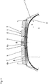
- FIG. 1 illustrates a schematic cross section through the tread region of a commercial vehicle tire with an embodiment according to the invention, explained in more detail.
- Fig. 1 are of the usual components of a commercial vehicle tire in radial design a tread 1, radially inside the tread 1 at least three-ply, preferably four-ply belt 2 whose belt layers have an electrically conductive Gürtelgummtechnik, reinforced with strength carriers radial carcass 3 and an air-tight inner layer 4.
- the non-designated side walls which may consist of an electrically conductive or of an electrically non-conductive rubber material, only the axially outer end portions are shown.
- the bead areas with bead cores, core profiles and the other reinforcement layers usually provided in the bead areas are not shown.
- the tread 1 is constructed in two layers in the radial direction and is composed of a tread cap 5 containing the profiling and a tread base 6 extending radially within the tread cap 5.
- the tread base 6 extends in the axial direction across the width of the tread cap 5.
- the tread 1 has four circumferential grooves 7 extending within the tread cap 5, which have the maximum tread depth usual for commercial vehicle tires, which is in particular 8.0 mm to 12.0 mm.
- the circumferential grooves 7 divide the tread 1 in circumferentially encircling profile ribs 8, which may be structured block-like or may consist of profile blocks.
- the axially outermost circumferential grooves are hereinafter referred to as shoulder-side circumferential grooves 7, the axially outside of the shoulder-side circumferential grooves 7 extending profile ribs below as shoulder-side profile ribs 8.
- the shoulder-side profile ribs 8 have within the ground contact surface each have a width b 1 of 10% to 25% of Width B of the tread 1 in the ground contacting part.
- the width b 1 ends tread inside of a radially extending plane which through those points of the tread surface, tread inside edge of the shoulder-side tread rib 8 runs, which are furthest on the outside of the tread. In just circumferential in the circumferential direction shoulder-side circumferential grooves 7, this plane extends along the tread inside edge.
- the tread base 6 is composed of a central base part 6a and one of these in the axial direction subsequent shoulder-side base part 6b together.
- Each base part 6a, 6b has an at least substantially constant axial width over the circumference of the tire.
- the shoulder-side base parts 6b extend radially within the respective shoulder-side tread rib 8 and reach the inside of the tread maximally up to the levels indicated by the lines l 1 .
- the tread cap 5 is made of an electrically non-conductive rubber compound and accordingly consists of an electrically non-conductive rubber material.
- the central base part 6a is made of a rubber compound containing only carbon black as a filler so that the rubber material of the central base part 6a has a high electrical conductivity.
- the rubber mixture on which the shoulder-side base parts 6b are based contains as filler either exclusively silica (finely divided silica) or silica in combination with a small proportion of carbon black.
- the shoulder-side base parts 6b are therefore electrically non-conductive, in the context of the present invention under an electrically non-conductive rubber material is to be understood as one which has an electrical resistance> 1 x 10 8 ohms.
- the tread cap 5 is split in two in the axial direction by a narrow rubber strip 9 extending in the radial direction and circulating in the circumferential direction, a so-called carbon center beam.
- the rubber strip 9 runs from the central base part 6a to the tread surface and is made of an electrically conductive rubber mixture, preferably of the rubber mixture of the central base part 6a.
- the carbon center beam therefore forms an electrically conductive passage between the tread surface and the central base portion 6a.
Description
Die Erfindung betrifft einen Nutzfahrzeugreifen gemäß dem Oberbegriff des unabhängigen Anspruchs 1. Es ist bekannt und üblich, in Laufstreifen von Nutzfahrzeugreifen Mischungsverbände bestehend aus einer Laufstreifencap und einer radialer innerhalb der Laufstreifencap verlaufenden Laufstreifenbase einzusetzen. Die Laufstreifencap und die Laufstreifenbase sind dabei aus unterschiedlichen Kautschukmischungen gefertigt. Diese Maßnahme gestattet es, bestimmte erwünschte Eigenschaften des Laufstreifens mit Hilfe von unterschiedlichen Mischungssystemen zu verbessern. Beispielsweise kann dadurch die Energiedissipation in der Laufstreifenbase reduziert werden, ohne dass die Abriebeigenschaften oder der Nassgriff des Reifens beeinflusst wird.The invention relates to a commercial vehicle tire according to the preamble of independent claim 1. It is known and common practice to use compound dressings in treads of commercial vehicle tires consisting of a tread cap and a tread base extending radially within the tread cap. The tread cap and the tread base are made of different rubber compounds. This measure makes it possible to improve certain desired characteristics of the tread by means of different mixing systems. For example, this can reduce the energy dissipation in the tread base without affecting the abrasiveness or wet grip of the tire.
Zur Erzielung eines niedrigen Rollwiderstandes und eines guten Nassgriffes ist es ferner üblich, Silica alleine oder in Kombination mit Ruß als Füllstoff(e) in den Kautschukmischungen der Laufstreifenbase und/oder der Laufstreifencap einzusetzen. Gummibauteile aus Silica enthaltenden Kautschukmischungen weisen im Vergleich zu ausschließlich mit Ruß gefüllten Kautschukmischungen eine deutlich geringere elektrische Leitfähigkeit auf. Um die im Betrieb des Reifens auftretende elektrostatische Aufladung ableiten zu können und um unangenehme Entladungsvorgänge zu verhindern, ist es ferner üblich, den Laufstreifen mit einem sogenannten Carbon Center Beam zu versehen. Dieser ist meist ein über den Laufstreifenumfang verlaufender, im Laufstreifen eingebauter Gummistreifen aus einer elektrisch leitfähigen Kautschukmischung, welcher beispielsweise aus der rußgefüllten Kautschukmischung der Laufstreifenbase gefertigt ist. Die elektrische leitfähige Laufstreifenbase enthält eine entsprechend große Rußmenge, um die Leitfähigkeit sicherzustellen, sodass die Laufstreifenbase eine relativ geringe Wärmeleitfähigkeit besitzt, wodurch der Rollwiderstand des Reifens erhöht ist.
Aus der
From the
Die
Bei Nutzfahrzeugreifen sind die Schulterbereiche hinsichtlich des Wärmeaufbaus besonders kritisch, ein hoher Wärmeaufbau wirkt sich auf die Lebensdauer des Reifens nachteilig aus. Der Erfindung liegt daher die Aufgabe zugrunde, bei einem Nutzfahrzeugreifen der eingangs genannten Art im Laufstreifen die an sich bekannte Silica-Technologie besonders vorteilhaft einzusetzen, um den Rollwiderstand und den Wärmeaufbau zu reduzieren und die Nassgriffeigenschaften zu verbessern.
Die gestellte Aufgabe wird erfindungsgemäß dadurch gelöst, dass der Baseteil aus dem elektrisch leitfähigen Gummimaterial den mittleren Bereich der Laufstreifenbase einnimmt, wobei seitlich dieses Baseteiles jeweils ein weiterer schulterseitig verlaufender Baseteil aus einem Silica enthaltenden elektrisch nicht leitfähigen, einen elektrischen Widerstand größer 108 Ohm aufweisenden, Gummimaterial anschließt, wobei jeder schulterseitige Baseteil laufstreifeninnenseitig höchstens bis zu einer sich in radialer Richtung erstreckenden Ebene reicht, welche durch jene Stellen der an der Laufstreifenoberfläche befindlichen, laufstreifeninnenseitigen Randkante der schulterseitigen Profilrippe verläuft, welche sich am weitesten laufstreifenaußenseitig befinden.
Durch Positionieren des elektrisch leitfähigen Baseteiles im mittleren Bereich der Laufstreifenbase, können die schulterseitigen Baseteile hinsichtlich Rollwiderstand optimiert werden. Dies erfolgt durch das Erstellen der schulterseitigen Baseteile aus einer Silica enthaltenden Kautschukmischung, wodurch die Wärmeleitfähigkeit in den Schulterbereichen verbessert wird. Durch die schulterseitigen Baseteile wird jedoch nicht nur der Rollwiderstand verringert sondern auch der Nassgriff verbessert.
Bei einer bevorzugten Ausführungsform der Erfindung enthält die dem Gummimaterial der schulterseitigen Baseteile zugrunde liegende Kautschukmischung als Füllstoff ausschließlich Silica. Bei einer weiteren, alternativen Ausführungsform der Erfindung enthält die dem Gummimaterial der schulterseitigen Baseteile zugrunde liegende Kautschukmischung als Füllstoffe Silica und Ruß, in derartigen Anteilen, dass die schulterseitigen Baseteile einen elektrischen Widerstand > 1 x 10⁸ Ohm aufweisen.The
In commercial vehicle tires, the shoulder areas are particularly critical in terms of heat build-up, high heat build-up adversely affects the life of the tire. The invention is therefore based on the object in a commercial vehicle tire of the type mentioned in the tread the known silica technology to use particularly advantageous to reduce the rolling resistance and heat buildup and to improve the wet grip properties.
The object is achieved according to the invention in that the base part of the electrically conductive rubber material occupies the central region of the tread base, wherein each side of this base part each further shoulder-side extending base part of a silica-containing electrically non-conductive, having an electrical resistance greater than 10 8 ohms, Rubber material connects, each shoulder-side base part tread inside reaches at most up to a radially extending plane which passes through those locations of the tread surface located on the tread surface, tread inside edge of the shoulder-side tread rib, which are furthest on the outside of the tread.
By positioning the electrically conductive base member in the central region of the tread base, the shoulder-side base members can be optimized in terms of rolling resistance. This is done by creating the shoulder-side base parts from a silica-containing rubber compound, thereby improving the thermal conductivity in the shoulder regions. By the shoulder-side base parts, however, not only the rolling resistance is reduced but also improves the wet grip.
In a preferred embodiment of the invention, the rubber mixture underlying the rubber material of the shoulder-side base parts contains as a filler exclusively silica. In a further alternative embodiment of the invention, the rubber mixture on which the rubber material of the shoulder-side base parts is based contains silica and carbon black as fillers, in proportions such that the shoulder-side base parts have an electrical resistance> 1 × 10 8 ohms.
Eine Maßnahme zur einfacheren Herstellung des Nutzfahrzeugreifens sieht vor, dass der die elektrisch leitfähige Verbindung zwischen dem Baseteil und der Außenfläche der Laufstreifencap herstellende Gummistreifen aus dem Gummimaterial des elektrisch leitfähigen Baseteiles besteht.A measure for the easier production of the commercial vehicle tire provides that the rubber strip producing the electrically conductive connection between the base part and the outer surface of the tread cap consists of the rubber material of the electrically conductive base part.
Der Rollwiderstand erfindungsgemäß ausgeführter Nutzfahrzeugreifen lässt sich zusätzlich dadurch senken, dass seine Seitenwände aus einem elektrisch nicht leitfähigen, einen elektrischen Widerstand größer 108 Ohm aufweisenden, Gummimaterial bestehen.The rolling resistance inventively executed commercial vehicle tires can be further reduced by the fact that its side walls of an electrically non-conductive, an electrical resistance greater than 10 8 ohm having, rubber material.
Weitere Merkmale, Vorteile und Einzelheiten der Erfindung werden nun anhand der einzigen Figur,
In
Der Laufstreifen 1 ist in radialer Richtung zweischichtig aufgebaut und setzt sich aus einer die Profilierung enthaltenden Laufstreifencap 5 und einer radialer innerhalb der Laufstreifencap 5 verlaufenden Laufstreifenbase 6 zusammen. Die Laufstreifenbase 6 erstreckt sich in axialer Richtung über die Breite der Laufstreifencap 5.The tread 1 is constructed in two layers in the radial direction and is composed of a tread cap 5 containing the profiling and a tread base 6 extending radially within the tread cap 5. The tread base 6 extends in the axial direction across the width of the tread cap 5.
Beim gezeigten Ausführungsbeispiel weist der Laufstreifen 1 vier innerhalb der Laufstreifencap 5 verlaufende Umfangsrillen 7 auf, welche die für Nutzfahrzeugreifen übliche maximale Profiltiefe, die insbesondere 8,0 mm bis 12,0 mm beträgt, aufweisen. Die Umfangsrillen 7 gliedern den Laufstreifen 1 in in Umfangsrichtung umlaufende Profilrippen 8, die blockartig strukturiert sein können oder aus Profilblöcken bestehen können. Die axial am weitesten außen liegenden Umfangsrillen sind nachfolgend als schulterseitige Umfangsrillen 7 bezeichnet, die axial außerhalb der schulterseitigen Umfangsrillen 7 verlaufenden Profilrippen nachfolgend als schulterseitige Profilrippen 8. Die schulterseitigen Profilrippen 8 weisen innerhalb der Bodenaufstandsfläche jeweils eine Breite b1 von 10% bis 25% der Breite B des Laufstreifens 1 im bodenberührenden Teil auf. Die Breite b1 endet laufstreifeninnenseitig an einer sich in radialer Richtung erstreckenden Ebene, welche durch jene Stellen der an der Laufstreifenoberfläche befindlichen, laufstreifeninnenseitigen Randkante der schulterseitigen Profilrippe 8 verläuft, welche sich am weitesten laufstreifenaußenseitig befinden. Bei gerade in Umfangsrichtung umlaufenden schulterseitigen Umfangsrillen 7 verläuft diese Ebene entlang der laufstreifeninnenseitigen Randkante. Diese Ebenen sind in der in
Die Laufstreifenbase 6 setzt sich aus einem zentralen Baseteil 6a und je einem an diesen in axialer Richtung anschließenden schulterseitigen Baseteil 6b zusammen. Jeder Baseteil 6a, 6b weist über den Reifenumfang eine zumindest im Wesentlichen konstante axiale Breite auf. Die schulterseitigen Baseteile 6b verlaufen radial innerhalb der jeweiligen schulterseitigen Profilrippe 8 und reichen laufstreifeninnenseitig maximal bis zu den durch die Linien l1 gekennzeichneten Ebenen.The tread base 6 is composed of a
Die Laufstreifencap 5 wird aus einer elektrisch nicht leitfähigen Kautschukmischung hergestellt und besteht dementsprechend aus einem elektrisch nicht leitfähigen Gummimaterial. Der zentrale Baseteil 6a wird aus einer Kautschukmischung, welche als Füllstoff ausschließlich Ruß enthält gefertigt, sodass das Gummimaterial des zentralen Baseteiles 6a eine hohe elektrische Leitfähigkeit aufweist. Die den schulterseitigen Baseteilen 6b zugrunde liegende Kautschukmischung enthält als Füllstoff entweder ausschließlich Silica (fein verteilte Kieselsäure) oder Silica in Kombination mit einem geringen Anteil an Ruß. Die schulterseitigen Baseteile 6b sind daher elektrisch nicht leitfähig, wobei im Rahmen der gegenständlichen Erfindung unter einem elektrisch nicht leitfähigen Gummimaterial ein solches zu verstehen ist, welches einen elektrischen Widerstand > 1 x 10⁸ Ohm aufweist.The tread cap 5 is made of an electrically non-conductive rubber compound and accordingly consists of an electrically non-conductive rubber material. The
Die Laufstreifencap 5 ist durch einen sich in radialer Richtung erstreckenden und in Umfangsrichtung umlaufenden schmalen Gummistreifen 9, einem sogenannten Carbon Center Beam, in axialer Richtung zweigeteilt. Der Gummistreifen 9 verläuft vom zentralen Baseteil 6a bis zur Laufstreifenoberfläche und ist aus einer elektrisch leitfähigen Kautschukmischung, vorzugsweise aus der Kautschukmischung des zentralen Baseteiles 6a, gefertigt. Der Carbon Center Beam bildet daher eine elektrisch leitfähige Passage zwischen der Laufstreifenoberfläche und dem zentralen Baseteil 6a.The tread cap 5 is split in two in the axial direction by a
- 11
- Laufstreifentread
- 22
- Gürtelbelt
- 33
- Radialkarkasseradial carcass
- 44
- Innenschichtinner layer
- 55
- Laufstreifencaptread cap
- 66
- LauftsreifenbaseRun Tire Base
- 6a6a
- zentraler Baseteilcentral base part
- 6b6b
- schulterseitiger Baseteilshoulder-side base part
- 77
- Umfangsrillecircumferential groove
- 88th
- Profilrippeprofile rib
- 99
- Gummistreifenrubber strips
Claims (5)
- Utility vehicle tyre of radial type of construction, having a tread (1) with two shoulder-side circumferential channels (7) which run in a circumferential direction and which in each case delimit a profile rib (3), running at the shoulder side, towards the tread inner side, wherein the tread (1) is of two-layer construction in a radial direction and is made up of a tread cap (5), which comprises the profiling, and of a tread base (6) running radially within the tread cap (5), wherein the tread cap (5) is composed of an electrically non-conductive rubber material which has an electrical resistance of greater than 108 ohm, and the tread base (6) has a base part (6a) composed of an electrically conductive rubber material, wherein a rubber strip (9) running in encircling fashion in a circumferential direction and composed of an electrically conductive rubber material extends in a radial direction through the tread cap (5) and produces an electrically conductive connection between the base part (6a) and the outer surface of the tread cap (5), wherein the base part (6a) composed of the electrically conductive rubber material occupies the central region of the tread base (6), characterized in that said base part (6a) is adjoined laterally by in each case one further base part (6b) which runs at the shoulder side and which is composed of a silica-containing, electrically non-conductive rubber material with an electrical resistance of greater than 108 ohm, wherein each shoulder-side base part (6b) extends towards the tread inner side at most as far as a plane (l1) which extends in a radial direction and which runs through those points of the marginal edge, situated on the tread surface and facing towards the tread inner side, of the shoulder-side profile rib (8) which are situated furthest towards the tread outer side.
- Utility vehicle tyre according to Claim 1, characterized in that the rubber mixture that forms a basis for the rubber material of the shoulder-side base parts (6b) comprises exclusively silica as filler material.
- Utility vehicle tyre according to Claim 1, characterized in that the rubber mixture that forms a basis for the rubber material of the shoulder-side base parts (6b) comprises silica and soot as filler materials, in fractions such that the shoulder-side base parts (6b) have an electrical resistance of > 1 x 10⁸ ohm.
- Utility vehicle tyre according to one of Claims 1 to 3, characterized in that the rubber strip (9) that produces the electrically conductive connection between the base part (6a) and the outer surface of the tread cap (5) is composed of the rubber material of the electrically conductive base part (6a).
- Utility vehicle tyre according to one of Claims 1 to 4, characterized in that said utility vehicle tyre has sidewalls composed of an electrically non-conductive rubber material which has an electrical resistance of greater than 108 ohm.
Priority Applications (1)
| Application Number | Priority Date | Filing Date | Title |
|---|---|---|---|
| PL16153063T PL3100876T3 (en) | 2015-05-19 | 2016-01-28 | Commercial vehicle tyre |
Applications Claiming Priority (1)
| Application Number | Priority Date | Filing Date | Title |
|---|---|---|---|
| DE102015209086.8A DE102015209086A1 (en) | 2015-05-19 | 2015-05-19 | Vehicle tires |
Publications (2)
| Publication Number | Publication Date |
|---|---|
| EP3100876A1 EP3100876A1 (en) | 2016-12-07 |
| EP3100876B1 true EP3100876B1 (en) | 2018-06-06 |
Family
ID=55237600
Family Applications (1)
| Application Number | Title | Priority Date | Filing Date |
|---|---|---|---|
| EP16153063.9A Active EP3100876B1 (en) | 2015-05-19 | 2016-01-28 | Commercial vehicle tyre |
Country Status (4)
| Country | Link |
|---|---|
| EP (1) | EP3100876B1 (en) |
| DE (1) | DE102015209086A1 (en) |
| ES (1) | ES2681667T3 (en) |
| PL (1) | PL3100876T3 (en) |
Family Cites Families (5)
| Publication number | Priority date | Publication date | Assignee | Title |
|---|---|---|---|---|
| EP0847880B1 (en) * | 1996-10-17 | 2002-12-18 | Sumitomo Rubber Industries Limited | Pneumatic tyre |
| WO2009022564A1 (en) * | 2007-08-10 | 2009-02-19 | Sumitomo Rubber Industries, Ltd. | Pneumatic tire |
| US20100132859A1 (en) * | 2008-12-02 | 2010-06-03 | Pascal Patrick Steiner | Tire with electrically non-conductive tread which contains electrically conductive rubber strip |
| DE102011001877A1 (en) | 2011-04-07 | 2012-10-11 | Continental Reifen Deutschland Gmbh | Pneumatic tire of vehicle, has base that is provided with primary layer portion that is made of low rolling resistance rubber composition and secondary layer portion that is made of electrically conductive rubber composition |
| JP2013006571A (en) * | 2011-06-27 | 2013-01-10 | Sumitomo Rubber Ind Ltd | Pneumatic tire |
-
2015
- 2015-05-19 DE DE102015209086.8A patent/DE102015209086A1/en not_active Withdrawn
-
2016
- 2016-01-28 ES ES16153063.9T patent/ES2681667T3/en active Active
- 2016-01-28 EP EP16153063.9A patent/EP3100876B1/en active Active
- 2016-01-28 PL PL16153063T patent/PL3100876T3/en unknown
Non-Patent Citations (1)
| Title |
|---|
| None * |
Also Published As
| Publication number | Publication date |
|---|---|
| PL3100876T3 (en) | 2018-11-30 |
| DE102015209086A1 (en) | 2016-11-24 |
| EP3100876A1 (en) | 2016-12-07 |
| ES2681667T3 (en) | 2018-09-14 |
Similar Documents
| Publication | Publication Date | Title |
|---|---|---|
| EP3019352B1 (en) | Pneumatic vehicle tyre | |
| EP3380343B1 (en) | Pneumatic vehicle tire | |
| EP3238958B1 (en) | Commercial vehicle tyres | |
| EP2944479B1 (en) | Pneumatic tyres for a vehicle | |
| DE19850766B4 (en) | Vehicle tires | |
| DE102013104114A1 (en) | Pneumatic vehicle tire and method for producing a pneumatic vehicle tire | |
| EP2848434B1 (en) | Pneumatic tyres for a vehicle | |
| EP2594413B1 (en) | Pneumatic tyre for a vehicle | |
| EP2939855B1 (en) | Pneumatic vehicle tyre comprising a strip from an electrically conductive rubber mixture | |
| EP3103661A1 (en) | Method for manufacturing an electrically conductive passage in a vehicle tyre | |
| EP3181380A1 (en) | Pneumatic vehicle tyres | |
| EP3100876B1 (en) | Commercial vehicle tyre | |
| EP3100874B1 (en) | Commercial vehicle tyre | |
| EP3362300B1 (en) | Commercial vehicle tires | |
| EP3680114B1 (en) | Pneumatic tyres for a vehicle | |
| EP2452837B1 (en) | Commercial vehicle tyres | |
| DE10032857A1 (en) | Pneumatic tire manufacture involves coating electroconductive rubber cement to tread rubber before vulcanization and forming cross-sipes of specified thickness at ground contact part during vulcanization molding | |
| EP3427978B1 (en) | Pneumatic tyres for a vehicle | |
| EP3181381B1 (en) | Pneumatic vehicle tyres | |
| DE102015225601A1 (en) | Vehicle tires | |
| EP3100875A1 (en) | Pneumatic vehicle tire | |
| DE102017116971B4 (en) | tire | |
| WO2015149957A1 (en) | Pneumatic vehicle tyre with electrically conductive sidewall | |
| EP4212357A1 (en) | Pneumatic tyre for vehicles | |
| DE102020209457A1 (en) | A pneumatic vehicle tire having an electrically conductive path |
Legal Events
| Date | Code | Title | Description |
|---|---|---|---|
| PUAI | Public reference made under article 153(3) epc to a published international application that has entered the european phase |
Free format text: ORIGINAL CODE: 0009012 |
|
| STAA | Information on the status of an ep patent application or granted ep patent |
Free format text: STATUS: THE APPLICATION HAS BEEN PUBLISHED |
|
| AK | Designated contracting states |
Kind code of ref document: A1 Designated state(s): AL AT BE BG CH CY CZ DE DK EE ES FI FR GB GR HR HU IE IS IT LI LT LU LV MC MK MT NL NO PL PT RO RS SE SI SK SM TR |
|
| AX | Request for extension of the european patent |
Extension state: BA ME |
|
| STAA | Information on the status of an ep patent application or granted ep patent |
Free format text: STATUS: REQUEST FOR EXAMINATION WAS MADE |
|
| 17P | Request for examination filed |
Effective date: 20170607 |
|
| RBV | Designated contracting states (corrected) |
Designated state(s): AL AT BE BG CH CY CZ DE DK EE ES FI FR GB GR HR HU IE IS IT LI LT LU LV MC MK MT NL NO PL PT RO RS SE SI SK SM TR |
|
| REG | Reference to a national code |
Ref country code: DE Ref legal event code: R079 Ref document number: 502016001131 Country of ref document: DE Free format text: PREVIOUS MAIN CLASS: B60C0019080000 Ipc: B60C0001000000 |
|
| GRAP | Despatch of communication of intention to grant a patent |
Free format text: ORIGINAL CODE: EPIDOSNIGR1 |
|
| STAA | Information on the status of an ep patent application or granted ep patent |
Free format text: STATUS: GRANT OF PATENT IS INTENDED |
|
| RIC1 | Information provided on ipc code assigned before grant |
Ipc: B60C 11/00 20060101ALI20180119BHEP Ipc: B60C 1/00 20060101AFI20180119BHEP Ipc: B60C 19/08 20060101ALI20180119BHEP |
|
| INTG | Intention to grant announced |
Effective date: 20180221 |
|
| GRAS | Grant fee paid |
Free format text: ORIGINAL CODE: EPIDOSNIGR3 |
|
| GRAA | (expected) grant |
Free format text: ORIGINAL CODE: 0009210 |
|
| STAA | Information on the status of an ep patent application or granted ep patent |
Free format text: STATUS: THE PATENT HAS BEEN GRANTED |
|
| AK | Designated contracting states |
Kind code of ref document: B1 Designated state(s): AL AT BE BG CH CY CZ DE DK EE ES FI FR GB GR HR HU IE IS IT LI LT LU LV MC MK MT NL NO PL PT RO RS SE SI SK SM TR |
|
| REG | Reference to a national code |
Ref country code: GB Ref legal event code: FG4D Free format text: NOT ENGLISH |
|
| REG | Reference to a national code |
Ref country code: CH Ref legal event code: EP Ref country code: AT Ref legal event code: REF Ref document number: 1005647 Country of ref document: AT Kind code of ref document: T Effective date: 20180615 |
|
| REG | Reference to a national code |
Ref country code: IE Ref legal event code: FG4D Free format text: LANGUAGE OF EP DOCUMENT: GERMAN |
|
| REG | Reference to a national code |
Ref country code: DE Ref legal event code: R096 Ref document number: 502016001131 Country of ref document: DE |
|
| REG | Reference to a national code |
Ref country code: ES Ref legal event code: FG2A Ref document number: 2681667 Country of ref document: ES Kind code of ref document: T3 Effective date: 20180914 |
|
| REG | Reference to a national code |
Ref country code: NL Ref legal event code: FP |
|
| REG | Reference to a national code |
Ref country code: LT Ref legal event code: MG4D |
|
| PG25 | Lapsed in a contracting state [announced via postgrant information from national office to epo] |
Ref country code: BG Free format text: LAPSE BECAUSE OF FAILURE TO SUBMIT A TRANSLATION OF THE DESCRIPTION OR TO PAY THE FEE WITHIN THE PRESCRIBED TIME-LIMIT Effective date: 20180906 Ref country code: CY Free format text: LAPSE BECAUSE OF FAILURE TO SUBMIT A TRANSLATION OF THE DESCRIPTION OR TO PAY THE FEE WITHIN THE PRESCRIBED TIME-LIMIT Effective date: 20180606 Ref country code: LT Free format text: LAPSE BECAUSE OF FAILURE TO SUBMIT A TRANSLATION OF THE DESCRIPTION OR TO PAY THE FEE WITHIN THE PRESCRIBED TIME-LIMIT Effective date: 20180606 Ref country code: FI Free format text: LAPSE BECAUSE OF FAILURE TO SUBMIT A TRANSLATION OF THE DESCRIPTION OR TO PAY THE FEE WITHIN THE PRESCRIBED TIME-LIMIT Effective date: 20180606 Ref country code: SE Free format text: LAPSE BECAUSE OF FAILURE TO SUBMIT A TRANSLATION OF THE DESCRIPTION OR TO PAY THE FEE WITHIN THE PRESCRIBED TIME-LIMIT Effective date: 20180606 Ref country code: NO Free format text: LAPSE BECAUSE OF FAILURE TO SUBMIT A TRANSLATION OF THE DESCRIPTION OR TO PAY THE FEE WITHIN THE PRESCRIBED TIME-LIMIT Effective date: 20180906 |
|
| PG25 | Lapsed in a contracting state [announced via postgrant information from national office to epo] |
Ref country code: HR Free format text: LAPSE BECAUSE OF FAILURE TO SUBMIT A TRANSLATION OF THE DESCRIPTION OR TO PAY THE FEE WITHIN THE PRESCRIBED TIME-LIMIT Effective date: 20180606 Ref country code: RS Free format text: LAPSE BECAUSE OF FAILURE TO SUBMIT A TRANSLATION OF THE DESCRIPTION OR TO PAY THE FEE WITHIN THE PRESCRIBED TIME-LIMIT Effective date: 20180606 Ref country code: LV Free format text: LAPSE BECAUSE OF FAILURE TO SUBMIT A TRANSLATION OF THE DESCRIPTION OR TO PAY THE FEE WITHIN THE PRESCRIBED TIME-LIMIT Effective date: 20180606 Ref country code: GR Free format text: LAPSE BECAUSE OF FAILURE TO SUBMIT A TRANSLATION OF THE DESCRIPTION OR TO PAY THE FEE WITHIN THE PRESCRIBED TIME-LIMIT Effective date: 20180907 |
|
| PG25 | Lapsed in a contracting state [announced via postgrant information from national office to epo] |
Ref country code: SK Free format text: LAPSE BECAUSE OF FAILURE TO SUBMIT A TRANSLATION OF THE DESCRIPTION OR TO PAY THE FEE WITHIN THE PRESCRIBED TIME-LIMIT Effective date: 20180606 Ref country code: CZ Free format text: LAPSE BECAUSE OF FAILURE TO SUBMIT A TRANSLATION OF THE DESCRIPTION OR TO PAY THE FEE WITHIN THE PRESCRIBED TIME-LIMIT Effective date: 20180606 Ref country code: RO Free format text: LAPSE BECAUSE OF FAILURE TO SUBMIT A TRANSLATION OF THE DESCRIPTION OR TO PAY THE FEE WITHIN THE PRESCRIBED TIME-LIMIT Effective date: 20180606 Ref country code: EE Free format text: LAPSE BECAUSE OF FAILURE TO SUBMIT A TRANSLATION OF THE DESCRIPTION OR TO PAY THE FEE WITHIN THE PRESCRIBED TIME-LIMIT Effective date: 20180606 Ref country code: IS Free format text: LAPSE BECAUSE OF FAILURE TO SUBMIT A TRANSLATION OF THE DESCRIPTION OR TO PAY THE FEE WITHIN THE PRESCRIBED TIME-LIMIT Effective date: 20181006 |
|
| PG25 | Lapsed in a contracting state [announced via postgrant information from national office to epo] |
Ref country code: SM Free format text: LAPSE BECAUSE OF FAILURE TO SUBMIT A TRANSLATION OF THE DESCRIPTION OR TO PAY THE FEE WITHIN THE PRESCRIBED TIME-LIMIT Effective date: 20180606 Ref country code: IT Free format text: LAPSE BECAUSE OF FAILURE TO SUBMIT A TRANSLATION OF THE DESCRIPTION OR TO PAY THE FEE WITHIN THE PRESCRIBED TIME-LIMIT Effective date: 20180606 |
|
| REG | Reference to a national code |
Ref country code: DE Ref legal event code: R097 Ref document number: 502016001131 Country of ref document: DE |
|
| PLBE | No opposition filed within time limit |
Free format text: ORIGINAL CODE: 0009261 |
|
| STAA | Information on the status of an ep patent application or granted ep patent |
Free format text: STATUS: NO OPPOSITION FILED WITHIN TIME LIMIT |
|
| 26N | No opposition filed |
Effective date: 20190307 |
|
| PG25 | Lapsed in a contracting state [announced via postgrant information from national office to epo] |
Ref country code: DK Free format text: LAPSE BECAUSE OF FAILURE TO SUBMIT A TRANSLATION OF THE DESCRIPTION OR TO PAY THE FEE WITHIN THE PRESCRIBED TIME-LIMIT Effective date: 20180606 Ref country code: SI Free format text: LAPSE BECAUSE OF FAILURE TO SUBMIT A TRANSLATION OF THE DESCRIPTION OR TO PAY THE FEE WITHIN THE PRESCRIBED TIME-LIMIT Effective date: 20180606 |
|
| PG25 | Lapsed in a contracting state [announced via postgrant information from national office to epo] |
Ref country code: MC Free format text: LAPSE BECAUSE OF FAILURE TO SUBMIT A TRANSLATION OF THE DESCRIPTION OR TO PAY THE FEE WITHIN THE PRESCRIBED TIME-LIMIT Effective date: 20180606 |
|
| REG | Reference to a national code |
Ref country code: CH Ref legal event code: PL |
|
| PG25 | Lapsed in a contracting state [announced via postgrant information from national office to epo] |
Ref country code: LU Free format text: LAPSE BECAUSE OF NON-PAYMENT OF DUE FEES Effective date: 20190128 |
|
| REG | Reference to a national code |
Ref country code: BE Ref legal event code: MM Effective date: 20190131 |
|
| REG | Reference to a national code |
Ref country code: IE Ref legal event code: MM4A |
|
| PG25 | Lapsed in a contracting state [announced via postgrant information from national office to epo] |
Ref country code: FR Free format text: LAPSE BECAUSE OF NON-PAYMENT OF DUE FEES Effective date: 20190131 |
|
| PG25 | Lapsed in a contracting state [announced via postgrant information from national office to epo] |
Ref country code: AL Free format text: LAPSE BECAUSE OF FAILURE TO SUBMIT A TRANSLATION OF THE DESCRIPTION OR TO PAY THE FEE WITHIN THE PRESCRIBED TIME-LIMIT Effective date: 20180606 Ref country code: BE Free format text: LAPSE BECAUSE OF NON-PAYMENT OF DUE FEES Effective date: 20190131 |
|
| PG25 | Lapsed in a contracting state [announced via postgrant information from national office to epo] |
Ref country code: CH Free format text: LAPSE BECAUSE OF NON-PAYMENT OF DUE FEES Effective date: 20190131 Ref country code: LI Free format text: LAPSE BECAUSE OF NON-PAYMENT OF DUE FEES Effective date: 20190131 |
|
| PG25 | Lapsed in a contracting state [announced via postgrant information from national office to epo] |
Ref country code: IE Free format text: LAPSE BECAUSE OF NON-PAYMENT OF DUE FEES Effective date: 20190128 |
|
| PG25 | Lapsed in a contracting state [announced via postgrant information from national office to epo] |
Ref country code: TR Free format text: LAPSE BECAUSE OF FAILURE TO SUBMIT A TRANSLATION OF THE DESCRIPTION OR TO PAY THE FEE WITHIN THE PRESCRIBED TIME-LIMIT Effective date: 20180606 |
|
| PG25 | Lapsed in a contracting state [announced via postgrant information from national office to epo] |
Ref country code: PT Free format text: LAPSE BECAUSE OF FAILURE TO SUBMIT A TRANSLATION OF THE DESCRIPTION OR TO PAY THE FEE WITHIN THE PRESCRIBED TIME-LIMIT Effective date: 20181008 Ref country code: MT Free format text: LAPSE BECAUSE OF FAILURE TO SUBMIT A TRANSLATION OF THE DESCRIPTION OR TO PAY THE FEE WITHIN THE PRESCRIBED TIME-LIMIT Effective date: 20180606 |
|
| GBPC | Gb: european patent ceased through non-payment of renewal fee |
Effective date: 20200128 |
|
| PG25 | Lapsed in a contracting state [announced via postgrant information from national office to epo] |
Ref country code: GB Free format text: LAPSE BECAUSE OF NON-PAYMENT OF DUE FEES Effective date: 20200128 |
|
| PG25 | Lapsed in a contracting state [announced via postgrant information from national office to epo] |
Ref country code: HU Free format text: LAPSE BECAUSE OF FAILURE TO SUBMIT A TRANSLATION OF THE DESCRIPTION OR TO PAY THE FEE WITHIN THE PRESCRIBED TIME-LIMIT; INVALID AB INITIO Effective date: 20160128 |
|
| REG | Reference to a national code |
Ref country code: AT Ref legal event code: MM01 Ref document number: 1005647 Country of ref document: AT Kind code of ref document: T Effective date: 20210128 |
|
| PG25 | Lapsed in a contracting state [announced via postgrant information from national office to epo] |
Ref country code: AT Free format text: LAPSE BECAUSE OF NON-PAYMENT OF DUE FEES Effective date: 20210128 |
|
| PG25 | Lapsed in a contracting state [announced via postgrant information from national office to epo] |
Ref country code: MK Free format text: LAPSE BECAUSE OF FAILURE TO SUBMIT A TRANSLATION OF THE DESCRIPTION OR TO PAY THE FEE WITHIN THE PRESCRIBED TIME-LIMIT Effective date: 20180606 |
|
| PGFP | Annual fee paid to national office [announced via postgrant information from national office to epo] |
Ref country code: PL Payment date: 20230123 Year of fee payment: 8 |
|
| PGFP | Annual fee paid to national office [announced via postgrant information from national office to epo] |
Ref country code: ES Payment date: 20230405 Year of fee payment: 8 |
|
| PGFP | Annual fee paid to national office [announced via postgrant information from national office to epo] |
Ref country code: NL Payment date: 20240119 Year of fee payment: 9 |
|
| REG | Reference to a national code |
Ref country code: DE Ref legal event code: R081 Ref document number: 502016001131 Country of ref document: DE Owner name: CONTINENTAL REIFEN DEUTSCHLAND GMBH, DE Free format text: FORMER OWNER: CONTINENTAL REIFEN DEUTSCHLAND GMBH, 30419 HANNOVER, DE |
|
| PGFP | Annual fee paid to national office [announced via postgrant information from national office to epo] |
Ref country code: ES Payment date: 20240223 Year of fee payment: 9 |
|
| PGFP | Annual fee paid to national office [announced via postgrant information from national office to epo] |
Ref country code: DE Payment date: 20240131 Year of fee payment: 9 |