EP3100869B1 - Active pen with an ink cartridge - Google Patents
Active pen with an ink cartridge Download PDFInfo
- Publication number
- EP3100869B1 EP3100869B1 EP16171481.1A EP16171481A EP3100869B1 EP 3100869 B1 EP3100869 B1 EP 3100869B1 EP 16171481 A EP16171481 A EP 16171481A EP 3100869 B1 EP3100869 B1 EP 3100869B1
- Authority
- EP
- European Patent Office
- Prior art keywords
- ink
- ball
- electronic device
- active pen
- tip
- Prior art date
- Legal status (The legal status is an assumption and is not a legal conclusion. Google has not performed a legal analysis and makes no representation as to the accuracy of the status listed.)
- Active
Links
Images

Classifications
-
- B—PERFORMING OPERATIONS; TRANSPORTING
- B43—WRITING OR DRAWING IMPLEMENTS; BUREAU ACCESSORIES
- B43K—IMPLEMENTS FOR WRITING OR DRAWING
- B43K7/00—Ball-point pens
- B43K7/02—Ink reservoirs; Ink cartridges
-
- B—PERFORMING OPERATIONS; TRANSPORTING
- B43—WRITING OR DRAWING IMPLEMENTS; BUREAU ACCESSORIES
- B43K—IMPLEMENTS FOR WRITING OR DRAWING
- B43K7/00—Ball-point pens
- B43K7/10—Arrangements for feeding ink to the ball points
-
- B—PERFORMING OPERATIONS; TRANSPORTING
- B43—WRITING OR DRAWING IMPLEMENTS; BUREAU ACCESSORIES
- B43K—IMPLEMENTS FOR WRITING OR DRAWING
- B43K29/00—Combinations of writing implements with other articles
-
- G—PHYSICS
- G06—COMPUTING OR CALCULATING; COUNTING
- G06F—ELECTRIC DIGITAL DATA PROCESSING
- G06F3/00—Input arrangements for transferring data to be processed into a form capable of being handled by the computer; Output arrangements for transferring data from processing unit to output unit, e.g. interface arrangements
- G06F3/01—Input arrangements or combined input and output arrangements for interaction between user and computer
- G06F3/03—Arrangements for converting the position or the displacement of a member into a coded form
- G06F3/033—Pointing devices displaced or positioned by the user, e.g. mice, trackballs, pens or joysticks; Accessories therefor
- G06F3/0354—Pointing devices displaced or positioned by the user, e.g. mice, trackballs, pens or joysticks; Accessories therefor with detection of two-dimensional [2D] relative movements between the device, or an operating part thereof, and a plane or surface, e.g. 2D mice, trackballs, pens or pucks
- G06F3/03545—Pens or stylus
-
- G—PHYSICS
- G06—COMPUTING OR CALCULATING; COUNTING
- G06F—ELECTRIC DIGITAL DATA PROCESSING
- G06F3/00—Input arrangements for transferring data to be processed into a form capable of being handled by the computer; Output arrangements for transferring data from processing unit to output unit, e.g. interface arrangements
- G06F3/01—Input arrangements or combined input and output arrangements for interaction between user and computer
- G06F3/03—Arrangements for converting the position or the displacement of a member into a coded form
- G06F3/033—Pointing devices displaced or positioned by the user, e.g. mice, trackballs, pens or joysticks; Accessories therefor
- G06F3/0354—Pointing devices displaced or positioned by the user, e.g. mice, trackballs, pens or joysticks; Accessories therefor with detection of two-dimensional [2D] relative movements between the device, or an operating part thereof, and a plane or surface, e.g. 2D mice, trackballs, pens or pucks
- G06F3/03545—Pens or stylus
- G06F3/03546—Pens or stylus using a rotatable ball at the tip as position detecting member
-
- G—PHYSICS
- G06—COMPUTING OR CALCULATING; COUNTING
- G06F—ELECTRIC DIGITAL DATA PROCESSING
- G06F3/00—Input arrangements for transferring data to be processed into a form capable of being handled by the computer; Output arrangements for transferring data from processing unit to output unit, e.g. interface arrangements
- G06F3/01—Input arrangements or combined input and output arrangements for interaction between user and computer
- G06F3/03—Arrangements for converting the position or the displacement of a member into a coded form
- G06F3/033—Pointing devices displaced or positioned by the user, e.g. mice, trackballs, pens or joysticks; Accessories therefor
- G06F3/038—Control and interface arrangements therefor, e.g. drivers or device-embedded control circuitry
- G06F3/0383—Signal control means within the pointing device
-
- G—PHYSICS
- G06—COMPUTING OR CALCULATING; COUNTING
- G06F—ELECTRIC DIGITAL DATA PROCESSING
- G06F3/00—Input arrangements for transferring data to be processed into a form capable of being handled by the computer; Output arrangements for transferring data from processing unit to output unit, e.g. interface arrangements
- G06F3/01—Input arrangements or combined input and output arrangements for interaction between user and computer
- G06F3/03—Arrangements for converting the position or the displacement of a member into a coded form
- G06F3/041—Digitisers, e.g. for touch screens or touch pads, characterised by the transducing means
- G06F3/044—Digitisers, e.g. for touch screens or touch pads, characterised by the transducing means by capacitive means
- G06F3/0442—Digitisers, e.g. for touch screens or touch pads, characterised by the transducing means by capacitive means using active external devices, e.g. active pens, for transmitting changes in electrical potential to be received by the digitiser
Definitions
- the present invention concerns an active pen with an ink cartridge.
- Touch devices are used in various application fields in which object presence detections are involved, such as, but not limited to, touch pads, touch panels, touch screens or projective capacitive displays. Touch devices detect passive objects touching the touch device and can determine the position of the touch. This allows for example a user control. Pens are often used as passive objects. In order to improve the position detection, active pens apply an electric signal on the tip of the pen for capacitive, inductive or electromagnetic coupling with the touch device.
- Pens for transferring ink on paper work normally mechanically by sucking ink from the ink reservoir during writing.
- the ink could be transferred by various transfer means like a roller ball, a porous material or by capillary means.
- electronic control for transferring the ink.
- Such electronic control is found in particular in multicolour pens mixing electronically three different ink colours.
- ink from three ink reservoirs are electronically pumped into a mixing chamber from which the mixed ink is transferred by a roller ball on the base material.
- US2009/0154982 and US2003/0138282 the ink of the three ink colour reservoirs is directly mixed on the roller ball by ink jets.
- WO2002/034549 , WO2002/034531 , EP1370425 or US6454482 discloses a pen for use on touch devices and on paper.
- the pen comprises a tip configured to be used on a touch screen, i.e. not transferring any ink from the ink reservoir to the tip.
- a printhead is arranged next to the tip in order to electronically transfer ink from the ink reservoir on paper, if the pen is not used on a touch screen.
- the writing experience of such a pen is more like a spray can than a classic pen.
- US2003118391 discloses a writing pen with a ball tip for transferring the ink from an ink reservoir to a paper.
- the ball can be prevented by a piezo-element or by an electromagnet from rolling, when a vicinity of the writing pen to a touch sensor is detected. This prevents the transfer of the ink from the ink reservoir to the touch screen.
- strong pressure or impacts on the ball could damage the electromagnet or the piezo-element and damage the ink-interruption mechanism.
- an electronic device for creating an ink jet from the ink reservoir onto the surface of the ball of the cartridge-tip allows arranging the electronic device for controlling the ink transfer in secure distance from the ball. Therefore, impacts and pressure shocks on the ball are not transferred to the electronic device.
- the same tip could be used in the electronic mode for emitting an electric signal, because the ink transfer to the tip is immediately stopped and the tip is connected to a control circuit of the active pen. Also the ink blocking mechanism does not interact with the electric signal applied to the tip.
- MEMS microelectromechanical systems
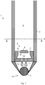
- Fig. 1 and 2 shows an embodiment of an ink cartridge 1.
- Fig. 1 shows a cross-sectional view along a longitudinal axis of one distal end of the ink cartridge 1.
- the cross-sectional view of Fig. 1 is indicated in Fig. 2 by the line I-I.
- Fig. 2 shows a cross-sectional view of the ink cartridge 1 along an axis being perpendicular to the longitudinal axis of the ink cartridge 1.
- the cross-sectional view of Fig. 2 is indicated in Fig. 1 by the line II-II.
- the ink cartridge 1 comprises an ink reservoir 3, a tip 14 and an electronic device 4.
- the tip 14 comprises a ball 5 which is supported rotatably around the centre of the ball 5.
- the ball 5 is arranged such that in each rotation position a first portion of the surface of the ball 5 is inside the ink cartridge and a second portion of the surface of the ball 5 is exposed to the exterior of the ink cartridge, more precisely on the tip 14 of the ink cartridge 1. If ink is transferred from the ink reservoir 13 onto the surface of the ball 5 in the first portion, the ink can be transferred to the exterior of the ink cartridge 1 by rotating the surface of the ball 5 with the ink to the second portion. This allows transferring ink from the interior of the ink cartridge 1 to the exterior of the ink cartridge 1, i.e. to the tip 14, simply by rotating the ball 5.
- the ink cartridge 1 has a longitudinal axis with two distal ends.
- the tip 14 is arranged at a first distal end of the ink cartridge 1.
- the tip 14 and/or the ball 5 are configured to be electrically conductive such that a signal can be applied to capacitively, inductively or electromagnetically couple with a position sensor (e.g. a touch device) to detect the position of the tip 14 on the position sensor.
- a position sensor e.g. a touch device
- the ink reservoir 3 is configured to contain ink.
- Ink is any material which is configured to colour by contact a material which shall be coloured. The contact is normally established by the tip 14.
- Colour in the sense of this invention includes any type of colour. This includes any colour of the classic colour spectrum, e.g. red, orange, yellow, green cyan, blue, violet. This includes any colour in the wider sense like black, grey and white. This includes any colour outside the visible spectrum of light, e.g. in the infrared or in the ultraviolet range, e.g. for a UV-pen. This can also include any mixture of the mentioned colours.
- the ink is configured to be deposited on the surface of the ball 5.
- the ink is further configured to be transferred from on the surface of the ball 5 from the first portion to the second portion.
- the ink is configured to be jetted out of the reservoir as will be explained in more detail below.
- the ink is liquid (including also viscous), but it is also possible to realise the ink in the ink reservoir 3 as particles.
- the ink cartridge 1 comprises a tubular body 2 forming at least partly the walls of the ink reservoir 3.
- the ink reservoir 3 has a first end pointing in the direction of the first distal end of the ink cartridge 1 or the tip 14 and a second end pointing in the direction of the second distal end of the ink cartridge.
- the second end of the ink reservoir 3 is preferably realized by a wall.
- the first end of the ink reservoir 3 is in the shown embodiment realized by the electronic device 4. It is however also possible that ink reservoir 3 can be coupled with the electronic device 4 in another way.
- the ink cartridge 1 is prefilled with the ink.
- the ink cartridge 1 can be a disposable. In another embodiment, the ink could be refilled in the ink reservoir 1, e.g. from the second end of the ink reservoir 3.
- the electronic device 4 is configured to transfer the ink from the ink reservoir 3 onto the surface of the ball 5 of the tip 14. According to the invention, the electronic device 4 is configured to create an ink jet 12 which jets the ink from the ink reservoir 3 on the surface of the ball 5.
- An ink jet according to the invention is a stream (also for a short time) of ink forced out of an aperture or nozzle.
- the ink jet has a jetting direction of the stream after the aperture or nozzle and optionally a limited opening angle.
- the ink outlet distinguishes itself from other ink jets in that the ink is distributed in all directions after the outlet. Therefore, the electronic device 4 is arranged between the ink reservoir 3 and the ball 5.
- the walls of the body 2, the electronic device 4 and the first portion of the ball 5 form a chamber 11.
- the surface of the ball 5 (in the first portion) is preferably arranged with a certain distance to the electronic device 4 in order to secure the electronic device 4 from damages from a strong force on the ball 5.
- the distance between the surface of the ball 5 and the electronic device 4 is preferably at least 0.5 millimetres, preferably at least 0.7 millimetres, preferably at least 1 millimetre, preferably at least 1.5 millimetres, preferably at least 2 millimetres.
- the present technology allows not only to easily switch on and off the ink transfer from the ink reservoir 3 on the ball 5, but it allows further to control the type of ink pattern created by the tip 14 of the pen.
- the ink quantity and/or the jet opening angle and/or the number of jets could be varied electronically. This could be used to control the intensity of the ink drawn by the tip 14.
- one single pen could create a continuous colour spectrum by the mixture of the at least two inks of the at least two ink reservoirs on the surface of the ball 5.
- the cartridge has only one ink reservoir 3 and is configured to provide only one ink colour.
- the electronic device 4 is realized preferably by a semi-conductor device, e.g. a silicon chip.
- the electronic device 4 is preferably realized by a microelectromechanical systems (MEMS) device.
- Fig. 1 shows an embodiment for such an electronic device 4.
- the ink jet 12 is here created by a silicon chip 7 with a piezo-electric element 6.
- the silicon chip comprises a chamber 9 connected with the ink reservoir 3 by at least one conduit 8 (here four conduits 8).
- the chamber 9 is connected with the chamber 11, i.e. with the surface of the ball 5 in the first portion, by at least one nozzle 10.
- the present embodiment comprises two nozzles 10, but any other number of nozzles 10 is possible.
- the ink jet 10 can be created by activating the piezo-electric element 6 for reducing the volume of the chamber 9 and forcing the ink through the nozzles 10 on the surface of the ball 5. If the piezo-electric element is not activated, the ink jet 12 is not created and the ink transfer on the ball 5 is interrupted.
- alternative embodiments for creating an ink jet are possible. E.g. a heating element could be used to created bubbles in the ink which create an ink jet on the ball 5. Technologies for creating ink jets are well known from ink jet printers. These technologies can be used for the electronic device 4.
- the electronic device 4 is preferably controlled by a signal received from a pen in which the ink cartridge 1 is installed. However, it is also possible that the electronic device 4 is partly or fully controlled by a sensor in the ink cartridge 1 and/or in the pen. A sensor could be applied to detect a second operation mode in which the ink transfer on the ball 5 must be stopped. This could be done for example by detecting an electric signal applied on the tip 14 or by detecting the vicinity of a touch sensor. It is also possible to detect in the first mode of operation, in which ink shall be emitted by the tip 14, when the ink jet must be (re)created or interrupted in order to avoid that too much ink is transferred on the surface of the ball 5 without being deposited on a paper. Such a sensor could detect the rotation of the ball 5, the amount of ink 5 on the surface of the ball 5, the movement of the ink cartridge 1, e.g. by an accelerometer, etc..
- the ink cartridge 1 is mounted in a pen.
- the ink cartridge 1 can be mounted such that the ink cartridge 1 can be replaced, once the ink cartridge 1 is empty. It is however also possible to arrange the elements of the ink cartridge 1 in a non-replaceable way in the pen. In this case, the ink reservoir 3 could be rechargeable or the pen itself is a disposable pen.
- the pen is an active pen for applying an electric signal on the tip 14 and/or ball 5 of the ink cartridge 1.
- the electric signal is applied also on the ball 5 so that the electric signal is emitted from the contact point with the position sensor.
- the distal part of the tip supporting the ball 5 should apply the electric signal, because this part is the closest to the touch screen after the ball 5 itself.
- Fig. 3 shows a schematic view of an embodiment of an active pen 20 with the above-described ink cartridge 1.
- the active pen 20 comprises the ink cartridge 1, a power supply 21, a controller 22, a pressure sensor 23 and a user input 24.
- the power supply 21 is preferably a battery. However, any other power supply like a power harvesting mechanism could be used.
- the power supply provides the controller 22 with power.
- the controller 22 is configured to operate the active pen 20 in a first operation mode in which ink is transferred by the ink jet 12 from the ink reservoir 3 onto the ball 5.
- the controller 22 is further configured to operate the active pen 20 in a second operation mode in which ink transfer from the ink reservoir 3 onto the ball 5 is stopped. Therefore, the controller 22 is electrically connected to the electronic device 4.
- the controller 22 is further electrically connected to the tip 14 and/or the ball 5 of the ink cartridge 1 in order to apply in the second operation mode an electric signal at the tip 14 and/or the ball 5.
- the electric signal is configured to create a capacitive, inductive or electromagnetic coupling with a position sensor.
- the electric signal is preferably a periodic signal, like an AC voltage at a certain frequency.
- the controller 22 has two separate contacts for contacting the tip 14 and/or the ball 5 and for contacting the electronic device 4.
- the electronic device 4 and the tip 14 and/or the ball 5 are connected with the controller 22 by the same electric line.
- the user input 24 is configured to switch between the first and the second operation mode. However, it is also possible that the switch between the first and the second operation mode is not performed by the user, but by a sensor.
- the user input 24 could further include on off switch for switching the power supply of the pen 20 off.
- the user input 24 could also include possibilities for the user to control parameters of the ink jet 12.
- the user input 24 could be a button or a switch or a more complex user interface, e.g. with a plurality of buttons or switches.
- the active pen 20 could comprise a pressure sensor 23 for measuring the pressure acting on the tip 14 and/or on the ball 5, when the active pen is operated in the second operation mode.
- the measured pen pressure can be transferred together with the electric signal over the tip 14 to the position detector.
- the pressure sensor 23 normally necessitates that the ink cartridge 1 moves along the longitudinal axis of the pen 20. In one embodiment, the movement along the longitudinal axis of the pen 20 is blocked in the first operation mode.
Landscapes
- Engineering & Computer Science (AREA)
- General Engineering & Computer Science (AREA)
- Theoretical Computer Science (AREA)
- Human Computer Interaction (AREA)
- Physics & Mathematics (AREA)
- General Physics & Mathematics (AREA)
- Pens And Brushes (AREA)
Description
- The present invention concerns an active pen with an ink cartridge.
- Touch devices are used in various application fields in which object presence detections are involved, such as, but not limited to, touch pads, touch panels, touch screens or projective capacitive displays. Touch devices detect passive objects touching the touch device and can determine the position of the touch. This allows for example a user control. Pens are often used as passive objects. In order to improve the position detection, active pens apply an electric signal on the tip of the pen for capacitive, inductive or electromagnetic coupling with the touch device.
- For writing or drawing on paper or any other base material, another type of pen is necessary which transfers ink on the base material. Therefore, nowadays two types of pen are necessary to interact, i.e. write or draw, on a touch sensor and to interact on paper.
- Pens for transferring ink on paper work normally mechanically by sucking ink from the ink reservoir during writing. The ink could be transferred by various transfer means like a roller ball, a porous material or by capillary means. However, there are also pens with electronic control for transferring the ink. Such electronic control is found in particular in multicolour pens mixing electronically three different ink colours. In
WO2009/091596 ink from three ink reservoirs are electronically pumped into a mixing chamber from which the mixed ink is transferred by a roller ball on the base material. InUS2009/0154982 andUS2003/0138282 , the ink of the three ink colour reservoirs is directly mixed on the roller ball by ink jets. -
WO2002/034549 ,WO2002/034531 ,EP1370425 orUS6454482 discloses a pen for use on touch devices and on paper. The pen comprises a tip configured to be used on a touch screen, i.e. not transferring any ink from the ink reservoir to the tip. A printhead is arranged next to the tip in order to electronically transfer ink from the ink reservoir on paper, if the pen is not used on a touch screen. However, the writing experience of such a pen is more like a spray can than a classic pen. -
US2003118391 discloses a writing pen with a ball tip for transferring the ink from an ink reservoir to a paper. The ball can be prevented by a piezo-element or by an electromagnet from rolling, when a vicinity of the writing pen to a touch sensor is detected. This prevents the transfer of the ink from the ink reservoir to the touch screen. However, strong pressure or impacts on the ball could damage the electromagnet or the piezo-element and damage the ink-interruption mechanism. - Therefore, it is an object to provide an active pen suitable for switching between an ink mode and an electronic mode which allows a classic writing experience in the ink mode and a robust way to control/stop the ink transfer from the ink reservoir on the paper for the electronic mode in which an electric signal is transmitted to a position sensor.
- According to the invention, these aims are achieved by means of an active pen according to
claim 1. - The use of an electronic device for creating an ink jet from the ink reservoir onto the surface of the ball of the cartridge-tip allows arranging the electronic device for controlling the ink transfer in secure distance from the ball. Therefore, impacts and pressure shocks on the ball are not transferred to the electronic device. At the same time, the same tip could be used in the electronic mode for emitting an electric signal, because the ink transfer to the tip is immediately stopped and the tip is connected to a control circuit of the active pen. Also the ink blocking mechanism does not interact with the electric signal applied to the tip.
- The dependent claims refer to further advantageous embodiments of the invention.
- The use of a semi-conductor device and/or a microelectromechanical systems (MEMS) device is an advantageous realization of an ink jet within an ink cartridge for a pen.
- The invention will be better understood with the aid of the description of an embodiment given by way of example and illustrated by the figures, in which:
-
Fig. 1 shows a first cross-section of an embodiment of an ink cartridge; -
Fig. 2 shows a second cross-section of the embodiment of the ink cartridge ofFig. 1 ; and -
Fig. 3 shows an embodiment of an active pen including an ink cartridge. -
Fig. 1 and2 shows an embodiment of anink cartridge 1.Fig. 1 shows a cross-sectional view along a longitudinal axis of one distal end of theink cartridge 1. The cross-sectional view ofFig. 1 is indicated inFig. 2 by the line I-I.Fig. 2 shows a cross-sectional view of theink cartridge 1 along an axis being perpendicular to the longitudinal axis of theink cartridge 1. The cross-sectional view ofFig. 2 is indicated inFig. 1 by the line II-II. - The
ink cartridge 1 comprises anink reservoir 3, a tip 14 and anelectronic device 4. - The tip 14 comprises a
ball 5 which is supported rotatably around the centre of theball 5. Theball 5 is arranged such that in each rotation position a first portion of the surface of theball 5 is inside the ink cartridge and a second portion of the surface of theball 5 is exposed to the exterior of the ink cartridge, more precisely on the tip 14 of theink cartridge 1. If ink is transferred from the ink reservoir 13 onto the surface of theball 5 in the first portion, the ink can be transferred to the exterior of theink cartridge 1 by rotating the surface of theball 5 with the ink to the second portion. This allows transferring ink from the interior of theink cartridge 1 to the exterior of theink cartridge 1, i.e. to the tip 14, simply by rotating theball 5. Such tips 14 are well-known in the state of the art from roller ball pens or ballpoint pens. Preferably, theink cartridge 1 has a longitudinal axis with two distal ends. Preferably, the tip 14 is arranged at a first distal end of theink cartridge 1. The tip 14 and/or theball 5 are configured to be electrically conductive such that a signal can be applied to capacitively, inductively or electromagnetically couple with a position sensor (e.g. a touch device) to detect the position of the tip 14 on the position sensor. - The
ink reservoir 3 is configured to contain ink. Ink is any material which is configured to colour by contact a material which shall be coloured. The contact is normally established by the tip 14. Colour in the sense of this invention includes any type of colour. This includes any colour of the classic colour spectrum, e.g. red, orange, yellow, green cyan, blue, violet. This includes any colour in the wider sense like black, grey and white. This includes any colour outside the visible spectrum of light, e.g. in the infrared or in the ultraviolet range, e.g. for a UV-pen. This can also include any mixture of the mentioned colours. The ink is configured to be deposited on the surface of theball 5. The ink is further configured to be transferred from on the surface of theball 5 from the first portion to the second portion. The ink is configured to be jetted out of the reservoir as will be explained in more detail below. Preferably, the ink is liquid (including also viscous), but it is also possible to realise the ink in theink reservoir 3 as particles. Preferably, theink cartridge 1 comprises atubular body 2 forming at least partly the walls of theink reservoir 3. Along the longitudinal axis of thetubular body 2 and/or theink cartridge 1, theink reservoir 3 has a first end pointing in the direction of the first distal end of theink cartridge 1 or the tip 14 and a second end pointing in the direction of the second distal end of the ink cartridge. The second end of theink reservoir 3 is preferably realized by a wall. The first end of theink reservoir 3 is in the shown embodiment realized by theelectronic device 4. It is however also possible thatink reservoir 3 can be coupled with theelectronic device 4 in another way. Preferably, theink cartridge 1 is prefilled with the ink. Theink cartridge 1 can be a disposable. In another embodiment, the ink could be refilled in theink reservoir 1, e.g. from the second end of theink reservoir 3. - The
electronic device 4 is configured to transfer the ink from theink reservoir 3 onto the surface of theball 5 of the tip 14. According to the invention, theelectronic device 4 is configured to create anink jet 12 which jets the ink from theink reservoir 3 on the surface of theball 5. An ink jet according to the invention is a stream (also for a short time) of ink forced out of an aperture or nozzle. The ink jet has a jetting direction of the stream after the aperture or nozzle and optionally a limited opening angle. The ink outlet distinguishes itself from other ink jets in that the ink is distributed in all directions after the outlet. Therefore, theelectronic device 4 is arranged between theink reservoir 3 and theball 5. The walls of thebody 2, theelectronic device 4 and the first portion of theball 5 form achamber 11. The surface of the ball 5 (in the first portion) is preferably arranged with a certain distance to theelectronic device 4 in order to secure theelectronic device 4 from damages from a strong force on theball 5. The distance between the surface of theball 5 and theelectronic device 4 is preferably at least 0.5 millimetres, preferably at least 0.7 millimetres, preferably at least 1 millimetre, preferably at least 1.5 millimetres, preferably at least 2 millimetres. By the creation of anink jet 12 in thechamber 11 from theelectronic device 4 onto the first portion of the surface of theball 5, the ink can be transferred on theball 5 in a safe and controllable way. The present technology allows not only to easily switch on and off the ink transfer from theink reservoir 3 on theball 5, but it allows further to control the type of ink pattern created by the tip 14 of the pen. For example the ink quantity and/or the jet opening angle and/or the number of jets could be varied electronically. This could be used to control the intensity of the ink drawn by the tip 14. In the case of at least two ink reservoirs with different colours, and different jets for each colour, one single pen could create a continuous colour spectrum by the mixture of the at least two inks of the at least two ink reservoirs on the surface of theball 5. However, in a preferred embodiment, the cartridge has only oneink reservoir 3 and is configured to provide only one ink colour. - The
electronic device 4 is realized preferably by a semi-conductor device, e.g. a silicon chip. Theelectronic device 4 is preferably realized by a microelectromechanical systems (MEMS) device.Fig. 1 shows an embodiment for such anelectronic device 4. Theink jet 12 is here created by asilicon chip 7 with a piezo-electric element 6. The silicon chip comprises achamber 9 connected with theink reservoir 3 by at least one conduit 8 (here four conduits 8). Thechamber 9 is connected with thechamber 11, i.e. with the surface of theball 5 in the first portion, by at least onenozzle 10. The present embodiment comprises twonozzles 10, but any other number ofnozzles 10 is possible. Theink jet 10 can be created by activating the piezo-electric element 6 for reducing the volume of thechamber 9 and forcing the ink through thenozzles 10 on the surface of theball 5. If the piezo-electric element is not activated, theink jet 12 is not created and the ink transfer on theball 5 is interrupted. However, alternative embodiments for creating an ink jet are possible. E.g. a heating element could be used to created bubbles in the ink which create an ink jet on theball 5. Technologies for creating ink jets are well known from ink jet printers. These technologies can be used for theelectronic device 4. - The
electronic device 4 is preferably controlled by a signal received from a pen in which theink cartridge 1 is installed. However, it is also possible that theelectronic device 4 is partly or fully controlled by a sensor in theink cartridge 1 and/or in the pen. A sensor could be applied to detect a second operation mode in which the ink transfer on theball 5 must be stopped. This could be done for example by detecting an electric signal applied on the tip 14 or by detecting the vicinity of a touch sensor. It is also possible to detect in the first mode of operation, in which ink shall be emitted by the tip 14, when the ink jet must be (re)created or interrupted in order to avoid that too much ink is transferred on the surface of theball 5 without being deposited on a paper. Such a sensor could detect the rotation of theball 5, the amount ofink 5 on the surface of theball 5, the movement of theink cartridge 1, e.g. by an accelerometer, etc.. - The
ink cartridge 1 is mounted in a pen. Theink cartridge 1 can be mounted such that theink cartridge 1 can be replaced, once theink cartridge 1 is empty. It is however also possible to arrange the elements of theink cartridge 1 in a non-replaceable way in the pen. In this case, theink reservoir 3 could be rechargeable or the pen itself is a disposable pen. - The pen is an active pen for applying an electric signal on the tip 14 and/or
ball 5 of theink cartridge 1. Preferably, the electric signal is applied also on theball 5 so that the electric signal is emitted from the contact point with the position sensor. However, it is also possible to apply the electric signal only (or in addition) to the rest of the tip, e.g. because the contact to the rotating ball might increase the complexity. In this case, the distal part of the tip supporting theball 5 should apply the electric signal, because this part is the closest to the touch screen after theball 5 itself.Fig. 3 shows a schematic view of an embodiment of anactive pen 20 with the above-describedink cartridge 1. Theactive pen 20 comprises theink cartridge 1, apower supply 21, acontroller 22, apressure sensor 23 and auser input 24. - The
power supply 21 is preferably a battery. However, any other power supply like a power harvesting mechanism could be used. The power supply provides thecontroller 22 with power. - The
controller 22 is configured to operate theactive pen 20 in a first operation mode in which ink is transferred by theink jet 12 from theink reservoir 3 onto theball 5. Thecontroller 22 is further configured to operate theactive pen 20 in a second operation mode in which ink transfer from theink reservoir 3 onto theball 5 is stopped. Therefore, thecontroller 22 is electrically connected to theelectronic device 4. Thecontroller 22 is further electrically connected to the tip 14 and/or theball 5 of theink cartridge 1 in order to apply in the second operation mode an electric signal at the tip 14 and/or theball 5. The electric signal is configured to create a capacitive, inductive or electromagnetic coupling with a position sensor. The electric signal is preferably a periodic signal, like an AC voltage at a certain frequency. In the shown embodiment, thecontroller 22 has two separate contacts for contacting the tip 14 and/or theball 5 and for contacting theelectronic device 4. However, it is also possible that theelectronic device 4 and the tip 14 and/or theball 5 are connected with thecontroller 22 by the same electric line. - The
user input 24 is configured to switch between the first and the second operation mode. However, it is also possible that the switch between the first and the second operation mode is not performed by the user, but by a sensor. Theuser input 24 could further include on off switch for switching the power supply of thepen 20 off. Theuser input 24 could also include possibilities for the user to control parameters of theink jet 12. Theuser input 24 could be a button or a switch or a more complex user interface, e.g. with a plurality of buttons or switches. - Optionally, the
active pen 20 could comprise apressure sensor 23 for measuring the pressure acting on the tip 14 and/or on theball 5, when the active pen is operated in the second operation mode. The measured pen pressure can be transferred together with the electric signal over the tip 14 to the position detector. Thepressure sensor 23 normally necessitates that theink cartridge 1 moves along the longitudinal axis of thepen 20. In one embodiment, the movement along the longitudinal axis of thepen 20 is blocked in the first operation mode.
Claims (11)
- Active pen comprising an ink cartridge and a control circuit,
wherein the ink cartridge comprises:an ink reservoir (3) for containing ink,a tip with a ball (5) rotatably supported for transferring ink from the ink reservoir to the tip during rotation of the ball;an electronic device (4) for creating an ink jet (12), said ink jet is configured to transfer the ink from the ink reservoir (3) onto the surface of the ball (5);wherein the control circuit (22) is electrically connected with the electronic device (4) and configured to switch the active pen between a first operation mode in which the electronic device (4) is controlled to transfer ink from the ink reservoir (5) to the surface of the ball (5) by the ink jet (12) and a second operation mode in which the electronic device (4) is controlled to switch off the ink jet (12) to interrupt the ink transfer from the ink reservoir (5) to the surface of the ball (5);
wherein the control circuit (22) is electrically connected with the tip and/or the ball (5) of the ink cartridge (1) and is configured to apply in the second mode an electric signal to the tip and/or the ball (5) for a capacitive or inductive or electromagnetic coupling with a touch device to detect the position of the tip and/or the ball (5) on the touch device. - Active pen according to the previous claim, wherein the electronic device (4) is a semi-conductor device.
- Active pen according to one of the previous claims, wherein the electronic device (4) is a microelectromechanical systems device.
- Active pen according to one of the previous claims, wherein the electronic device (4) comprises a piezoelectric element or a heating element for creating the ink jet (12).
- Active pen according to the previous claim, wherein the electronic device (4) comprises an ink chamber (9) connected to the ink reservoir (3) and a nozzle (10) connecting the ink chamber (9) with the ball (5), wherein the piezoelectric element (6) reduces the volume of the ink chamber (9) to press ink through the nozzle (10) in order to create the ink jet (12).
- Active pen according to one of the previous claims, wherein the electronic device (4) is arranged with a distance of at least 0.5 millimetres from the surface of the ball (5).
- Active pen according to one of the previous claims, wherein the ink cartridge comprises a second ink reservoir for containing a second ink, wherein the electronic device (4) or a second electronic device is configured to create a second ink jet for transferring the second ink from the second ink reservoir to the surface of the ball (5).
- Active pen according to one of claims 1 to 6 configured to jet ink in only one colour on the ball (5).
- Active pen according to one of the previous claims comprising a pressure sensor (23) configured to measure in the second operation mode the pressure applied on the ink cartridge (1).
- Active pen according to the previous claim, wherein the ink cartridge (1) is mounted such in the pen (20) to be movable along a longitudinal axis of the pen in order to measure the pressure on the ink cartridge (1), wherein the pen (20) is further configured to block the movement of the ink cartridge (1) in the first operation mode.
- Active pen according to one of the previous claims, wherein the coupling with the touch device is capacitive.
Applications Claiming Priority (1)
| Application Number | Priority Date | Filing Date | Title |
|---|---|---|---|
| CH00801/15A CH711164B1 (en) | 2015-06-04 | 2015-06-04 | Ink cartridge and pen comprising such an ink cartridge. |
Publications (2)
| Publication Number | Publication Date |
|---|---|
| EP3100869A1 EP3100869A1 (en) | 2016-12-07 |
| EP3100869B1 true EP3100869B1 (en) | 2019-09-18 |
Family
ID=53298062
Family Applications (1)
| Application Number | Title | Priority Date | Filing Date |
|---|---|---|---|
| EP16171481.1A Active EP3100869B1 (en) | 2015-06-04 | 2016-05-26 | Active pen with an ink cartridge |
Country Status (2)
| Country | Link |
|---|---|
| EP (1) | EP3100869B1 (en) |
| CH (1) | CH711164B1 (en) |
Families Citing this family (2)
| Publication number | Priority date | Publication date | Assignee | Title |
|---|---|---|---|---|
| CN119948441A (en) * | 2022-09-26 | 2025-05-06 | 斑马株式会社 | Active stylus |
| JP2024046935A (en) * | 2022-09-26 | 2024-04-05 | ゼブラ株式会社 | Active stylus |
Family Cites Families (7)
| Publication number | Priority date | Publication date | Assignee | Title |
|---|---|---|---|---|
| KR100721381B1 (en) | 1999-10-25 | 2007-05-23 | 실버브룩 리서치 피티와이 리미티드 | Electronically controllable pen with sensor |
| KR100582098B1 (en) | 2000-10-20 | 2006-05-22 | 실버브룩 리서치 피티와이 리미티드 | Electronically Controllable Pen Cartridge Assembly |
| DE60035809T2 (en) * | 2000-10-20 | 2008-04-17 | Silverbrook Research Pty. Ltd., Balmain | PRINT HEAD FOR PEN |
| GB2383014A (en) | 2001-12-14 | 2003-06-18 | Hewlett Packard Co | Combined writing pen and input stylus for an electronic screen with proximity sensor |
| US6749355B2 (en) * | 2002-01-24 | 2004-06-15 | Hewlett-Packard Development Company, L.P. | Writing instrument with user-controlled ink color |
| WO2009076597A1 (en) * | 2007-12-12 | 2009-06-18 | University Of Southern California | Multicolor writing and painting instruments |
| WO2009091596A1 (en) * | 2008-01-16 | 2009-07-23 | Judith Bender | Million color pen |
-
2015
- 2015-06-04 CH CH00801/15A patent/CH711164B1/en not_active IP Right Cessation
-
2016
- 2016-05-26 EP EP16171481.1A patent/EP3100869B1/en active Active
Non-Patent Citations (1)
| Title |
|---|
| None * |
Also Published As
| Publication number | Publication date |
|---|---|
| CH711164A1 (en) | 2016-12-15 |
| CH711164B1 (en) | 2020-04-30 |
| EP3100869A1 (en) | 2016-12-07 |
Similar Documents
| Publication | Publication Date | Title |
|---|---|---|
| JP7210468B2 (en) | Electrostatic atomizer for liquids and method of operating the electrostatic atomizer | |
| US9028026B2 (en) | Apparatus for printing on 3-dimensional surface using electrohydrodynamic force | |
| JP3955528B2 (en) | Pen print head | |
| WO2007100587A2 (en) | Hand-held ink jet pen | |
| EP3100869A1 (en) | Active pen with an ink cartridge | |
| KR20090130107A (en) | Electrostatic sprayer | |
| JP2020040272A (en) | Portable image formation device | |
| ZA200409899B (en) | Liquid jet writing instrument | |
| CN108621580A (en) | A kind of electrohydrodynamic printing head and device | |
| CA2591539A1 (en) | Electrostatic paint sprayer | |
| JP2016131914A (en) | Ink jet device | |
| JP2010188264A (en) | Discharge apparatus | |
| US7654665B2 (en) | Ink jet pen having a free ink chamber | |
| JP4658069B2 (en) | Liquid jet writing instrument | |
| TWI444302B (en) | Omnidirectional portable printer | |
| EP3099490A1 (en) | Valve | |
| JP4970448B2 (en) | Droplet ejecting head, writing instrument including the droplet ejecting head, and method for ejecting droplets from the droplet ejecting head | |
| US8313178B2 (en) | Fluid delivery system | |
| KR20180137727A (en) | Apparatus for dispensing | |
| KR101262423B1 (en) | A multi-nozzle liquid droplet ejecting head a writing instrument comprising such a head and a method of ejecting liquid droplets from same | |
| KR101734430B1 (en) | Liquid dispenser | |
| KR101231039B1 (en) | Fluid circulating type electrostatic ink-jet nozzle | |
| KR101191284B1 (en) | Fluid circulating type electrostatic ink-jet nozzle | |
| JP2013151070A (en) | Liquid jetting head and liquid jetting device | |
| Tse et al. | Airflow Assisted Electrohydrodynamic Jet Printing: An Advanced Micro-Additive Manufacturing Technique |
Legal Events
| Date | Code | Title | Description |
|---|---|---|---|
| PUAI | Public reference made under article 153(3) epc to a published international application that has entered the european phase |
Free format text: ORIGINAL CODE: 0009012 |
|
| STAA | Information on the status of an ep patent application or granted ep patent |
Free format text: STATUS: THE APPLICATION HAS BEEN PUBLISHED |
|
| AK | Designated contracting states |
Kind code of ref document: A1 Designated state(s): AL AT BE BG CH CY CZ DE DK EE ES FI FR GB GR HR HU IE IS IT LI LT LU LV MC MK MT NL NO PL PT RO RS SE SI SK SM TR |
|
| AX | Request for extension of the european patent |
Extension state: BA ME |
|
| STAA | Information on the status of an ep patent application or granted ep patent |
Free format text: STATUS: REQUEST FOR EXAMINATION WAS MADE |
|
| 17P | Request for examination filed |
Effective date: 20170515 |
|
| RBV | Designated contracting states (corrected) |
Designated state(s): AL AT BE BG CH CY CZ DE DK EE ES FI FR GB GR HR HU IE IS IT LI LT LU LV MC MK MT NL NO PL PT RO RS SE SI SK SM TR |
|
| STAA | Information on the status of an ep patent application or granted ep patent |
Free format text: STATUS: EXAMINATION IS IN PROGRESS |
|
| 17Q | First examination report despatched |
Effective date: 20171121 |
|
| RAP1 | Party data changed (applicant data changed or rights of an application transferred) |
Owner name: ADVANCED SILICON SA |
|
| GRAP | Despatch of communication of intention to grant a patent |
Free format text: ORIGINAL CODE: EPIDOSNIGR1 |
|
| STAA | Information on the status of an ep patent application or granted ep patent |
Free format text: STATUS: GRANT OF PATENT IS INTENDED |
|
| INTG | Intention to grant announced |
Effective date: 20190424 |
|
| GRAS | Grant fee paid |
Free format text: ORIGINAL CODE: EPIDOSNIGR3 |
|
| GRAA | (expected) grant |
Free format text: ORIGINAL CODE: 0009210 |
|
| STAA | Information on the status of an ep patent application or granted ep patent |
Free format text: STATUS: THE PATENT HAS BEEN GRANTED |
|
| AK | Designated contracting states |
Kind code of ref document: B1 Designated state(s): AL AT BE BG CH CY CZ DE DK EE ES FI FR GB GR HR HU IE IS IT LI LT LU LV MC MK MT NL NO PL PT RO RS SE SI SK SM TR |
|
| REG | Reference to a national code |
Ref country code: GB Ref legal event code: FG4D |
|
| REG | Reference to a national code |
Ref country code: CH Ref legal event code: EP |
|
| REG | Reference to a national code |
Ref country code: DE Ref legal event code: R096 Ref document number: 602016020704 Country of ref document: DE |
|
| REG | Reference to a national code |
Ref country code: CH Ref legal event code: NV Representative=s name: P&TS SA, CH Ref country code: AT Ref legal event code: REF Ref document number: 1180826 Country of ref document: AT Kind code of ref document: T Effective date: 20191015 |
|
| REG | Reference to a national code |
Ref country code: IE Ref legal event code: FG4D |
|
| REG | Reference to a national code |
Ref country code: NL Ref legal event code: MP Effective date: 20190918 |
|
| PG25 | Lapsed in a contracting state [announced via postgrant information from national office to epo] |
Ref country code: FI Free format text: LAPSE BECAUSE OF FAILURE TO SUBMIT A TRANSLATION OF THE DESCRIPTION OR TO PAY THE FEE WITHIN THE PRESCRIBED TIME-LIMIT Effective date: 20190918 Ref country code: SE Free format text: LAPSE BECAUSE OF FAILURE TO SUBMIT A TRANSLATION OF THE DESCRIPTION OR TO PAY THE FEE WITHIN THE PRESCRIBED TIME-LIMIT Effective date: 20190918 Ref country code: NO Free format text: LAPSE BECAUSE OF FAILURE TO SUBMIT A TRANSLATION OF THE DESCRIPTION OR TO PAY THE FEE WITHIN THE PRESCRIBED TIME-LIMIT Effective date: 20191218 Ref country code: HR Free format text: LAPSE BECAUSE OF FAILURE TO SUBMIT A TRANSLATION OF THE DESCRIPTION OR TO PAY THE FEE WITHIN THE PRESCRIBED TIME-LIMIT Effective date: 20190918 Ref country code: LT Free format text: LAPSE BECAUSE OF FAILURE TO SUBMIT A TRANSLATION OF THE DESCRIPTION OR TO PAY THE FEE WITHIN THE PRESCRIBED TIME-LIMIT Effective date: 20190918 Ref country code: BG Free format text: LAPSE BECAUSE OF FAILURE TO SUBMIT A TRANSLATION OF THE DESCRIPTION OR TO PAY THE FEE WITHIN THE PRESCRIBED TIME-LIMIT Effective date: 20191218 |
|
| REG | Reference to a national code |
Ref country code: LT Ref legal event code: MG4D |
|
| PG25 | Lapsed in a contracting state [announced via postgrant information from national office to epo] |
Ref country code: AL Free format text: LAPSE BECAUSE OF FAILURE TO SUBMIT A TRANSLATION OF THE DESCRIPTION OR TO PAY THE FEE WITHIN THE PRESCRIBED TIME-LIMIT Effective date: 20190918 Ref country code: LV Free format text: LAPSE BECAUSE OF FAILURE TO SUBMIT A TRANSLATION OF THE DESCRIPTION OR TO PAY THE FEE WITHIN THE PRESCRIBED TIME-LIMIT Effective date: 20190918 Ref country code: GR Free format text: LAPSE BECAUSE OF FAILURE TO SUBMIT A TRANSLATION OF THE DESCRIPTION OR TO PAY THE FEE WITHIN THE PRESCRIBED TIME-LIMIT Effective date: 20191219 Ref country code: RS Free format text: LAPSE BECAUSE OF FAILURE TO SUBMIT A TRANSLATION OF THE DESCRIPTION OR TO PAY THE FEE WITHIN THE PRESCRIBED TIME-LIMIT Effective date: 20190918 |
|
| REG | Reference to a national code |
Ref country code: DE Ref legal event code: R082 Ref document number: 602016020704 Country of ref document: DE Representative=s name: BECK & ROESSIG - EUROPEAN PATENT ATTORNEYS, DE |
|
| REG | Reference to a national code |
Ref country code: AT Ref legal event code: MK05 Ref document number: 1180826 Country of ref document: AT Kind code of ref document: T Effective date: 20190918 |
|
| PG25 | Lapsed in a contracting state [announced via postgrant information from national office to epo] |
Ref country code: RO Free format text: LAPSE BECAUSE OF FAILURE TO SUBMIT A TRANSLATION OF THE DESCRIPTION OR TO PAY THE FEE WITHIN THE PRESCRIBED TIME-LIMIT Effective date: 20190918 Ref country code: PL Free format text: LAPSE BECAUSE OF FAILURE TO SUBMIT A TRANSLATION OF THE DESCRIPTION OR TO PAY THE FEE WITHIN THE PRESCRIBED TIME-LIMIT Effective date: 20190918 Ref country code: ES Free format text: LAPSE BECAUSE OF FAILURE TO SUBMIT A TRANSLATION OF THE DESCRIPTION OR TO PAY THE FEE WITHIN THE PRESCRIBED TIME-LIMIT Effective date: 20190918 Ref country code: NL Free format text: LAPSE BECAUSE OF FAILURE TO SUBMIT A TRANSLATION OF THE DESCRIPTION OR TO PAY THE FEE WITHIN THE PRESCRIBED TIME-LIMIT Effective date: 20190918 Ref country code: EE Free format text: LAPSE BECAUSE OF FAILURE TO SUBMIT A TRANSLATION OF THE DESCRIPTION OR TO PAY THE FEE WITHIN THE PRESCRIBED TIME-LIMIT Effective date: 20190918 Ref country code: PT Free format text: LAPSE BECAUSE OF FAILURE TO SUBMIT A TRANSLATION OF THE DESCRIPTION OR TO PAY THE FEE WITHIN THE PRESCRIBED TIME-LIMIT Effective date: 20200120 Ref country code: AT Free format text: LAPSE BECAUSE OF FAILURE TO SUBMIT A TRANSLATION OF THE DESCRIPTION OR TO PAY THE FEE WITHIN THE PRESCRIBED TIME-LIMIT Effective date: 20190918 Ref country code: IT Free format text: LAPSE BECAUSE OF FAILURE TO SUBMIT A TRANSLATION OF THE DESCRIPTION OR TO PAY THE FEE WITHIN THE PRESCRIBED TIME-LIMIT Effective date: 20190918 |
|
| PG25 | Lapsed in a contracting state [announced via postgrant information from national office to epo] |
Ref country code: CZ Free format text: LAPSE BECAUSE OF FAILURE TO SUBMIT A TRANSLATION OF THE DESCRIPTION OR TO PAY THE FEE WITHIN THE PRESCRIBED TIME-LIMIT Effective date: 20190918 Ref country code: SM Free format text: LAPSE BECAUSE OF FAILURE TO SUBMIT A TRANSLATION OF THE DESCRIPTION OR TO PAY THE FEE WITHIN THE PRESCRIBED TIME-LIMIT Effective date: 20190918 Ref country code: IS Free format text: LAPSE BECAUSE OF FAILURE TO SUBMIT A TRANSLATION OF THE DESCRIPTION OR TO PAY THE FEE WITHIN THE PRESCRIBED TIME-LIMIT Effective date: 20200224 Ref country code: SK Free format text: LAPSE BECAUSE OF FAILURE TO SUBMIT A TRANSLATION OF THE DESCRIPTION OR TO PAY THE FEE WITHIN THE PRESCRIBED TIME-LIMIT Effective date: 20190918 |
|
| REG | Reference to a national code |
Ref country code: DE Ref legal event code: R097 Ref document number: 602016020704 Country of ref document: DE |
|
| PLBE | No opposition filed within time limit |
Free format text: ORIGINAL CODE: 0009261 |
|
| STAA | Information on the status of an ep patent application or granted ep patent |
Free format text: STATUS: NO OPPOSITION FILED WITHIN TIME LIMIT |
|
| PG2D | Information on lapse in contracting state deleted |
Ref country code: IS |
|
| PG25 | Lapsed in a contracting state [announced via postgrant information from national office to epo] |
Ref country code: DK Free format text: LAPSE BECAUSE OF FAILURE TO SUBMIT A TRANSLATION OF THE DESCRIPTION OR TO PAY THE FEE WITHIN THE PRESCRIBED TIME-LIMIT Effective date: 20190918 Ref country code: IS Free format text: LAPSE BECAUSE OF FAILURE TO SUBMIT A TRANSLATION OF THE DESCRIPTION OR TO PAY THE FEE WITHIN THE PRESCRIBED TIME-LIMIT Effective date: 20200119 |
|
| 26N | No opposition filed |
Effective date: 20200619 |
|
| PG25 | Lapsed in a contracting state [announced via postgrant information from national office to epo] |
Ref country code: SI Free format text: LAPSE BECAUSE OF FAILURE TO SUBMIT A TRANSLATION OF THE DESCRIPTION OR TO PAY THE FEE WITHIN THE PRESCRIBED TIME-LIMIT Effective date: 20190918 |
|
| REG | Reference to a national code |
Ref country code: DE Ref legal event code: R119 Ref document number: 602016020704 Country of ref document: DE |
|
| PG25 | Lapsed in a contracting state [announced via postgrant information from national office to epo] |
Ref country code: MC Free format text: LAPSE BECAUSE OF FAILURE TO SUBMIT A TRANSLATION OF THE DESCRIPTION OR TO PAY THE FEE WITHIN THE PRESCRIBED TIME-LIMIT Effective date: 20190918 Ref country code: LI Free format text: LAPSE BECAUSE OF NON-PAYMENT OF DUE FEES Effective date: 20200531 Ref country code: CH Free format text: LAPSE BECAUSE OF NON-PAYMENT OF DUE FEES Effective date: 20200531 |
|
| REG | Reference to a national code |
Ref country code: BE Ref legal event code: MM Effective date: 20200531 |
|
| GBPC | Gb: european patent ceased through non-payment of renewal fee |
Effective date: 20200526 |
|
| PG25 | Lapsed in a contracting state [announced via postgrant information from national office to epo] |
Ref country code: LU Free format text: LAPSE BECAUSE OF NON-PAYMENT OF DUE FEES Effective date: 20200526 |
|
| PG25 | Lapsed in a contracting state [announced via postgrant information from national office to epo] |
Ref country code: GB Free format text: LAPSE BECAUSE OF NON-PAYMENT OF DUE FEES Effective date: 20200526 Ref country code: IE Free format text: LAPSE BECAUSE OF NON-PAYMENT OF DUE FEES Effective date: 20200526 Ref country code: FR Free format text: LAPSE BECAUSE OF NON-PAYMENT OF DUE FEES Effective date: 20200531 |
|
| PG25 | Lapsed in a contracting state [announced via postgrant information from national office to epo] |
Ref country code: DE Free format text: LAPSE BECAUSE OF NON-PAYMENT OF DUE FEES Effective date: 20201201 Ref country code: BE Free format text: LAPSE BECAUSE OF NON-PAYMENT OF DUE FEES Effective date: 20200531 |
|
| PG25 | Lapsed in a contracting state [announced via postgrant information from national office to epo] |
Ref country code: TR Free format text: LAPSE BECAUSE OF FAILURE TO SUBMIT A TRANSLATION OF THE DESCRIPTION OR TO PAY THE FEE WITHIN THE PRESCRIBED TIME-LIMIT Effective date: 20190918 Ref country code: MT Free format text: LAPSE BECAUSE OF FAILURE TO SUBMIT A TRANSLATION OF THE DESCRIPTION OR TO PAY THE FEE WITHIN THE PRESCRIBED TIME-LIMIT Effective date: 20190918 Ref country code: CY Free format text: LAPSE BECAUSE OF FAILURE TO SUBMIT A TRANSLATION OF THE DESCRIPTION OR TO PAY THE FEE WITHIN THE PRESCRIBED TIME-LIMIT Effective date: 20190918 |
|
| PG25 | Lapsed in a contracting state [announced via postgrant information from national office to epo] |
Ref country code: MK Free format text: LAPSE BECAUSE OF FAILURE TO SUBMIT A TRANSLATION OF THE DESCRIPTION OR TO PAY THE FEE WITHIN THE PRESCRIBED TIME-LIMIT Effective date: 20190918 |