EP3100846B1 - Detachable scanning and supporting module of 3d printer - Google Patents
Detachable scanning and supporting module of 3d printer Download PDFInfo
- Publication number
- EP3100846B1 EP3100846B1 EP16167721.6A EP16167721A EP3100846B1 EP 3100846 B1 EP3100846 B1 EP 3100846B1 EP 16167721 A EP16167721 A EP 16167721A EP 3100846 B1 EP3100846 B1 EP 3100846B1
- Authority
- EP
- European Patent Office
- Prior art keywords
- scanning
- base
- module
- printing
- disposed
- Prior art date
- Legal status (The legal status is an assumption and is not a legal conclusion. Google has not performed a legal analysis and makes no representation as to the accuracy of the status listed.)
- Not-in-force
Links
Images





Classifications
-
- H—ELECTRICITY
- H04—ELECTRIC COMMUNICATION TECHNIQUE
- H04N—PICTORIAL COMMUNICATION, e.g. TELEVISION
- H04N1/00—Scanning, transmission or reproduction of documents or the like, e.g. facsimile transmission; Details thereof
- H04N1/00795—Reading arrangements
- H04N1/00827—Arrangements for reading an image from an unusual original, e.g. 3-dimensional objects
-
- B—PERFORMING OPERATIONS; TRANSPORTING
- B29—WORKING OF PLASTICS; WORKING OF SUBSTANCES IN A PLASTIC STATE IN GENERAL
- B29C—SHAPING OR JOINING OF PLASTICS; SHAPING OF MATERIAL IN A PLASTIC STATE, NOT OTHERWISE PROVIDED FOR; AFTER-TREATMENT OF THE SHAPED PRODUCTS, e.g. REPAIRING
- B29C64/00—Additive manufacturing, i.e. manufacturing of three-dimensional [3D] objects by additive deposition, additive agglomeration or additive layering, e.g. by 3D printing, stereolithography or selective laser sintering
- B29C64/20—Apparatus for additive manufacturing; Details thereof or accessories therefor
- B29C64/227—Driving means
- B29C64/232—Driving means for motion along the axis orthogonal to the plane of a layer
-
- B—PERFORMING OPERATIONS; TRANSPORTING
- B29—WORKING OF PLASTICS; WORKING OF SUBSTANCES IN A PLASTIC STATE IN GENERAL
- B29C—SHAPING OR JOINING OF PLASTICS; SHAPING OF MATERIAL IN A PLASTIC STATE, NOT OTHERWISE PROVIDED FOR; AFTER-TREATMENT OF THE SHAPED PRODUCTS, e.g. REPAIRING
- B29C64/00—Additive manufacturing, i.e. manufacturing of three-dimensional [3D] objects by additive deposition, additive agglomeration or additive layering, e.g. by 3D printing, stereolithography or selective laser sintering
- B29C64/20—Apparatus for additive manufacturing; Details thereof or accessories therefor
- B29C64/227—Driving means
- B29C64/236—Driving means for motion in a direction within the plane of a layer
-
- B—PERFORMING OPERATIONS; TRANSPORTING
- B29—WORKING OF PLASTICS; WORKING OF SUBSTANCES IN A PLASTIC STATE IN GENERAL
- B29C—SHAPING OR JOINING OF PLASTICS; SHAPING OF MATERIAL IN A PLASTIC STATE, NOT OTHERWISE PROVIDED FOR; AFTER-TREATMENT OF THE SHAPED PRODUCTS, e.g. REPAIRING
- B29C64/00—Additive manufacturing, i.e. manufacturing of three-dimensional [3D] objects by additive deposition, additive agglomeration or additive layering, e.g. by 3D printing, stereolithography or selective laser sintering
- B29C64/20—Apparatus for additive manufacturing; Details thereof or accessories therefor
- B29C64/245—Platforms or substrates
-
- B—PERFORMING OPERATIONS; TRANSPORTING
- B33—ADDITIVE MANUFACTURING TECHNOLOGY
- B33Y—ADDITIVE MANUFACTURING, i.e. MANUFACTURING OF THREE-DIMENSIONAL [3D] OBJECTS BY ADDITIVE DEPOSITION, ADDITIVE AGGLOMERATION OR ADDITIVE LAYERING, e.g. BY 3D PRINTING, STEREOLITHOGRAPHY OR SELECTIVE LASER SINTERING
- B33Y50/00—Data acquisition or data processing for additive manufacturing
-
- H—ELECTRICITY
- H04—ELECTRIC COMMUNICATION TECHNIQUE
- H04N—PICTORIAL COMMUNICATION, e.g. TELEVISION
- H04N1/00—Scanning, transmission or reproduction of documents or the like, e.g. facsimile transmission; Details thereof
- H04N1/00519—Constructional details not otherwise provided for, e.g. housings, covers
- H04N1/00538—Modular devices, i.e. allowing combinations of separate components, removal or replacement of components
- H04N1/00541—Modular devices, i.e. allowing combinations of separate components, removal or replacement of components with detachable image reading apparatus
-
- H—ELECTRICITY
- H04—ELECTRIC COMMUNICATION TECHNIQUE
- H04N—PICTORIAL COMMUNICATION, e.g. TELEVISION
- H04N1/00—Scanning, transmission or reproduction of documents or the like, e.g. facsimile transmission; Details thereof
- H04N1/00519—Constructional details not otherwise provided for, e.g. housings, covers
- H04N1/00559—Mounting or support of components or elements
-
- H—ELECTRICITY
- H04—ELECTRIC COMMUNICATION TECHNIQUE
- H04N—PICTORIAL COMMUNICATION, e.g. TELEVISION
- H04N1/00—Scanning, transmission or reproduction of documents or the like, e.g. facsimile transmission; Details thereof
- H04N1/04—Scanning arrangements, i.e. arrangements for the displacement of active reading or reproducing elements relative to the original or reproducing medium, or vice versa
-
- B—PERFORMING OPERATIONS; TRANSPORTING
- B33—ADDITIVE MANUFACTURING TECHNOLOGY
- B33Y—ADDITIVE MANUFACTURING, i.e. MANUFACTURING OF THREE-DIMENSIONAL [3D] OBJECTS BY ADDITIVE DEPOSITION, ADDITIVE AGGLOMERATION OR ADDITIVE LAYERING, e.g. BY 3D PRINTING, STEREOLITHOGRAPHY OR SELECTIVE LASER SINTERING
- B33Y30/00—Apparatus for additive manufacturing; Details thereof or accessories therefor
-
- H—ELECTRICITY
- H04—ELECTRIC COMMUNICATION TECHNIQUE
- H04N—PICTORIAL COMMUNICATION, e.g. TELEVISION
- H04N2201/00—Indexing scheme relating to scanning, transmission or reproduction of documents or the like, and to details thereof
- H04N2201/04—Scanning arrangements
- H04N2201/0402—Arrangements not specific to a particular one of the scanning methods covered by groups H04N1/04 - H04N1/207
- H04N2201/0446—Constructional details not otherwise provided for, e.g. mounting of scanning components
Definitions
- the present invention relates to a 3D printer, and more specifically to a detachable scanning and supporting module of a 3D printer.
- 3D printing is a technique of rapid molding, it is also named as additive manufacturing (AM), or layer molding.
- AM additive manufacturing
- 3D printing is based on a digital model file, then adherable materials, such as metallic powders or plastics, can be accumulated layer by layer based on the digital model file so as to form an object, and thus a 3D structure with any shapes can be formed.
- 3D printing in general, the materials in the feed tube is squeezed out and accumulated based on the order of computer graphic software, and thus a 3D structure is formed. Further, in order to mold a 3D structure rapidly, a 3D information of the object can be obtained by a 3D scanning device in advance, and then the 3D information is read by the order of computer graphic software, so as to perform 3D printing.
- 3D scanning and 3D printing are two individual modules.
- a 3D printer which can perform both 3D scanning and 3D printing, usually has a larger inner space and has a larger size. However, the size is large and it occupies a large space, which should be improved.
- the inventor proposes the disclosure so as to improve the above described deficiencies.
- US-A-20140271964 discloses a system including a 3D printer, a scanning and driving module and a detachable scanning and supporting module for the 3D printer according to the preamble of claim 1.
- the scanning and supporting module is, however, not detachably combined with the scanning and driving module to be driven by the scanning and driving module.
- a 3D printer can perform printing and scanning functions (operations) even within a limited space and constricted space of 3D printers.
- a system including a 3D printer, a scanning and driving module and a detachable scanning and supporting module for the 3D printer.
- the scanning and supporting module of the 3D printer is detachable, i.e. is configured to be releasably coupled with a 3D printer, and can be removed from and coupled with the 3D printer, wherein the scanning and supporting module is detachably combined with the scanning and driving module, such that the scanning and supporting module can be easily detached when not in use.
- the system according to the present invention comprises a machine body, a printing platform, a scanning and driving module and a scanning and supporting module.
- the machine body has a bottom plate.
- the printing platform is disposed on the bottom plate.
- the printing platform comprises a slide track and a printing substrate.
- the printing substrate is capable of moving corresponding to the slide track.
- the scanning and driving module is disposed on the bottom plate.
- the scanning and driving module and the slide track are staggeredly disposed such that the scanning and driving module and the slide track do not interfere with the movement of the printing substrate.
- the scanning and supporting module is detachably combined with the scanning and driving module and is driven by the scanning and driving module.
- the scanning and driving module of the present invention is disposed beneath the XY plane of the printing substrate, such that the scanning and driving module does not interfere the movement of the printing substrate; further, part of the slide track may pass through the scanning and driving module along the X-axis, the slide track and the scanning and driving module may overlap along the X-axis, such that the scanning and driving module and the printing platform are disposed in the same plane of a limited space in a 3D printer.
- the scanning and supporting module of the present invention is configured to be detachably combined with the scanning and driving module; thereby, when the scanning and supporting module is not in use, the scanning and supporting module can be easily detached from the scanning and driving module, which further benefits the convenience and utility of the present invention.
- a detachable scanning and supporting module of a 3D printer comprises a machine body 10, a printing platform 20, a printing module 30, a scanning and driving module 40 and a scanning and supporting module 50.
- the printing platform 20, the printing module 30, the scanning and driving module 40 and the scanning and supporting module 50 are disposed inside the machine body 10.
- the scanning and driving module 40 and the scanning and supporting module 50 are configured for scanning an object, obtaining a 3D information of the object, and inputting a computer graphic software, which is used as an input order in the subsequent processes, so as to control the printing platform 20 and the printing module 30 for printing.
- the machine body 10 has a bottom plate 11.
- the printing platform 20 is disposed above the bottom plate 11.
- the printing platform 20 comprises a slide track 21 and a printing substrate 22.
- the printing substrate 22 is capable of moving corresponding to the slide track 21 along an X-axis.
- the slide track 21 comprises a base 211 and a plurality of grooves 212.
- the printing substrate 22 is movably combined to the plurality of grooves 212.
- the printing module 30 is disposed inside the machine body 10, and is capable of moving along two directions of up-and-down and left-and-right.
- the printing module 30 comprises a printing and driving structure 31 and a printing head 32.
- the printing head 32 is driven by the printing and driving structure 31 so as to move corresponding to the printing substrate 22 along a Y-axis and a Z-axis.
- the scanning and driving module 40 is disposed on the bottom plate 11.
- the scanning and driving module 40 and the slide track 21 are staggeredly disposed such that they do not interfere with the movement of the printing substrate 22. More specifically, a moving plane is defined when the printing substrate 22 moves on the slide track 21, and the location of the scanning and driving module 40 do not interfere the moving plane. In this embodiment, the scanning and driving module 40 is located beneath the moving plane. Thus, the scanning and driving module 40 and the printing platform 20 are disposed on the same plane in a limited space.
- the scanning and supporting module 50 is disposed above the slide track 21.
- the scanning and supporting module 50 is detachably combined with the scanning and driving module 40 and is driven by the scanning and driving module 40.
- the scanning and supporting module 50 can be disposed at one end of the slide track 21, and the printing substrate 22 is disposed at the other end of the slide track 21.
- the more detailed structure of the scanning and driving module 40 is described in the followings.
- the scanning and driving module 40 comprises a base 41 and a motor 42, and the motor 42 is disposed inside the base 41. Moreover, part of the slide track 21 passes through the base 41 along the X-axis.
- the base 41 is U-shaped and has a notch 410, and one end of the slide track 21 is located inside the notch 410.
- the base 41 of the scanning and driving module 40 has a plurality of latching blocks 411.
- the scanning and supporting module 50 has a plurality of buckle structures 51, which corresponds to the plurality of latching blocks 411.
- the scanning and supporting module 50 is combined with the base 41 of the scanning and driving module 40 by the plurality of buckle structures 51 engaging with the plurality of latching blocks 411.
- the base 41 has a plurality of latching blocks 411 at the two sides of the notch 410 respectively, and the two lateral sides of the scanning and supporting module 50 has a buckle structure 51 corresponding to the latching blocks 411.
- each of the buckle structure 51 comprises a pushing member 511 and a spring 512, and the spring 512 elastically abuts the pushing member 511.
- the pushing member 511 has a plurality of slots 5110 and a plurality of hooks 5111, which is formed in the plurality of slots 510.
- the pushing member 511 forces the plurality of hooks 5111 engaging with the plurality of latching blocks 411 by the spring 512.
- the scanning and supporting module 50 comprises a carrier platform 52, a rotating disk 53 and a gearset 54.
- the rotating disk 53 and the gearset 54 are combined with the carrier platform 52; in addition, the pushing member 511 and the spring 512 are disposed inside the carrier platform 52.
- the carrier platform 52 has an opening 520.
- a push button 5112 is formed at one end of the push member 511. When the push member 511 is combined with the carrier platform 52, the push button 5112 exposes the opening 520.
- a bottom plane of the rotating disk 53 further comprises a rotating gear 531, and the rotating gear 531 engages with the gearset 54.
- the scanning and driving module 40 further comprises a sensor 43 disposed at the base 41 (referring to Fig. 1 ).
- the scanning and supporting module 50 further comprises a blocking elastic arm 55.
- the blocking elastic arm 55 exposes from a bottom plane of the carrier platform 52 so as to block the sensor 43. Thereby, when the blocking elastic arm 55 blocks the sensor 43, it can be realized that the scanning and supporting module 50 rotates for one revolution.
- Figs. 5 to 7 are a partial and sectional view of the scanning and supporting module combined with the scanning and driving module, a schematic view of a push member when being pressed and a schematic view of a push member after being pressed according to the disclosure.
- the scanning and supporting module 50 is combined with the base 41 of the scanning and driving module 40 by the plurality of buckle structures 51 engaging with the plurality of latching blocks 411.
- the scanning and supporting module 50 when the scanning and supporting module 50 is not in use, the scanning and supporting module 50 can be detached from the scanning and driving module 40.
- the push button 5112 of the scanning and supporting module 50 is pressed, and the pushing member 511 is forced to press the spring 512, and the plurality of hooks 5111 is detached from the plurality of latching blocks 411; thus, as shown in Fig. 6 , the scanning and supporting module 50 can be easily detached from the scanning and driving module 40.
- a detachable scanning and supporting module of a 3D printer comprises a machine body 10a, a printing platform 20a, a printing module 30a, a scanning and driving module 40a and a scanning and supporting module 50a.
- the printing platform 20a and the scanning and driving module 40a are disposed above a bottom plate 11a of the machine body 10a.
- the printing platform 20a comprises a slide track 21a and a movable printing substrate 22a.
- the scanning and driving module 40a and the slide track 21a are staggeredly disposed such that they do not interfere with the movement of the printing substrate 22a.
- the scanning and supporting module 50a is detachably combined with the scanning and driving module 40a and is driven by the scanning and driving module 40a.
- the scanning and driving module 40a comprises a first base 41a', a second base 41a" and a motor 42a.
- the motor 42a is disposed at the first base 41a' (but not limited thereto), and the first base 41a' and the second base 41a" have a plurality of latching blocks 411a.
- one end of the slide track 21a is disposed between the first base 41a' and the second base 41a".
- a detachable scanning and supporting module of a 3D printer comprises a machine body 10b a printing platform 20b, a printing module 30b, a scanning and driving module 40b and a scanning and supporting module 50b.
- the printing platform 20b and the scanning and driving module 40b are disposed above a bottom plate 11b of the machine body 10b.
- the printing platform 20b comprises a slide track 21b and a movable printing substrate 22b.
- the scanning and driving module 40b and the slide track 21b are staggeredly disposed such that they do not interfere with the movement of the printing substrate 22b.
- the scanning and supporting module 50b is detachably combined with the scanning and driving module 40b and is driven by the scanning and driving module 40b.
- the scanning and driving module 40b comprises a base 41b and a motor 42b, and the motor 42b is disposed inside the base 41b.
- the difference between this embodiment and previous embodiment is how the slide track 21b and the base 41b are disposed.
- the slide track 21b comprises a first track 21b' and a second track 21b", the first track 21b' and the second track 21b" are separately disposed; in addition, the base 41b is disposed between the first track 21b' and the second track 21b"; preferably, the base 41b is disposed between one end of the first track 21b' and one end of the second track 21b".
- a further aspect of the present invention relates to a 3D printer including a detachable scanning and supporting module as set forth in the present application.
Landscapes
- Engineering & Computer Science (AREA)
- Chemical & Material Sciences (AREA)
- Materials Engineering (AREA)
- Multimedia (AREA)
- Signal Processing (AREA)
- Manufacturing & Machinery (AREA)
- Physics & Mathematics (AREA)
- Mechanical Engineering (AREA)
- Optics & Photonics (AREA)
- Facsimile Scanning Arrangements (AREA)
Description
- The present invention relates to a 3D printer, and more specifically to a detachable scanning and supporting module of a 3D printer.
- 3D printing is a technique of rapid molding, it is also named as additive manufacturing (AM), or layer molding. 3D printing is based on a digital model file, then adherable materials, such as metallic powders or plastics, can be accumulated layer by layer based on the digital model file so as to form an object, and thus a 3D structure with any shapes can be formed.
- In 3D printing, in general, the materials in the feed tube is squeezed out and accumulated based on the order of computer graphic software, and thus a 3D structure is formed. Further, in order to mold a 3D structure rapidly, a 3D information of the object can be obtained by a 3D scanning device in advance, and then the 3D information is read by the order of computer graphic software, so as to perform 3D printing.
- However, in present 3D printers, 3D scanning and 3D printing are two individual modules. A 3D printer, which can perform both 3D scanning and 3D printing, usually has a larger inner space and has a larger size. However, the size is large and it occupies a large space, which should be improved.
- Accordingly, in order to solve the above problem, the inventor proposes the disclosure so as to improve the above described deficiencies.
-
US-A-20140271964 discloses a system including a 3D printer, a scanning and driving module and a detachable scanning and supporting module for the 3D printer according to the preamble of claim 1. The scanning and supporting module is, however, not detachably combined with the scanning and driving module to be driven by the scanning and driving module. - It is an object of the present invention to further improve the use of space in 3D printers in an efficient and simple but reliable manner.
- This problem is solved by a system including a 3D printer, a scanning and driving module and detachable scanning and supporting module for the 3D printer as claimed by claim 1. Further advantageous embodiments are the subject-matter of the dependent claims.
- With a scanning and supporting module for (of) a 3D printer according to the present invention a 3D printer can perform printing and scanning functions (operations) even within a limited space and constricted space of 3D printers.
- According to the present invention there is provided a system including a 3D printer, a scanning and driving module and a detachable scanning and supporting module for the 3D printer. The scanning and supporting module of the 3D printer is detachable, i.e. is configured to be releasably coupled with a 3D printer, and can be removed from and coupled with the 3D printer, wherein the scanning and supporting module is detachably combined with the scanning and driving module, such that the scanning and supporting module can be easily detached when not in use.
- The system according to the present invention comprises a machine body, a printing platform, a scanning and driving module and a scanning and supporting module. The machine body has a bottom plate. The printing platform is disposed on the bottom plate.
- According to the present invention the printing platform comprises a slide track and a printing substrate. The printing substrate is capable of moving corresponding to the slide track. The scanning and driving module is disposed on the bottom plate. The scanning and driving module and the slide track are staggeredly disposed such that the scanning and driving module and the slide track do not interfere with the movement of the printing substrate. The scanning and supporting module is detachably combined with the scanning and driving module and is driven by the scanning and driving module.
- As compared with conventional technique, the scanning and driving module of the present invention is disposed beneath the XY plane of the printing substrate, such that the scanning and driving module does not interfere the movement of the printing substrate; further, part of the slide track may pass through the scanning and driving module along the X-axis, the slide track and the scanning and driving module may overlap along the X-axis, such that the scanning and driving module and the printing platform are disposed in the same plane of a limited space in a 3D printer. In addition, the scanning and supporting module of the present invention is configured to be detachably combined with the scanning and driving module; thereby, when the scanning and supporting module is not in use, the scanning and supporting module can be easily detached from the scanning and driving module, which further benefits the convenience and utility of the present invention.
- Those and other aspects and associated implementations and features of disclosed wrist exerciser
designs are described in greater detail in the drawings, the description and the claims. - The disclosed wrist exerciser designs will become more fully understood from the detailed description given herein below along with the accompanying drawings which are for illustration only, thus are not limitative of the disclosed wrist exerciser designs.
- FIG. 1
- shows a perspective view of a detachable scanning and supporting module of a 3D printer according to the disclosure;
- FIG. 2
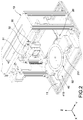
- shows a perspective view of a 3D printer according to the disclosure;
- FIG. 3
- shows an exploded view of a scanning and supporting module of a 3D printer along one direction according to the disclosure;
- FIG. 4
- shows an exploded view of a scanning and supporting module of a 3D printer along another direction according to the disclosure;
- FIG. 5
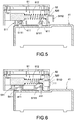
- shows a partial and sectional view of a scanning and supporting module combined with a scanning and driving module according to the disclosure;
- FIG. 6
- shows a schematic view of a push member when being pressed according to the disclosure;
- FIG. 7
- shows a schematic view of a push member after being pressed according to the disclosure;
- FIG. 8
- shows a perspective view of a detachable scanning and supporting module of a 3D printer according to the second embodiment of the present invention; and
- FIG. 9
- shows a perspective view of a detachable scanning and supporting module of a 3D printer according to the third embodiment of the present invention.
- In the following detailed description, for purposes of explanation, numerous specific details are set forth in order to provide a thorough understanding of the disclosed embodiments. It will be apparent, however, that one or more embodiments may be practiced without these specific details. In other instances, well-known structures and devices are schematically shown in order to simplify the drawing
- Referring to
Figs. 1 to 4 , which are a perspective view of a detachable scanning and supporting module, a perspective view of a 3D printer and exploded views of a scanning and supporting module of a 3D printer along two directions according to the disclosure. According to the disclosure, a detachable scanning and supporting module of a 3D printer comprises amachine body 10, aprinting platform 20, aprinting module 30, a scanning anddriving module 40 and a scanning and supportingmodule 50. Theprinting platform 20, theprinting module 30, the scanning anddriving module 40 and the scanning and supportingmodule 50 are disposed inside themachine body 10. Further, the scanning anddriving module 40 and the scanning and supportingmodule 50 are configured for scanning an object, obtaining a 3D information of the object, and inputting a computer graphic software, which is used as an input order in the subsequent processes, so as to control theprinting platform 20 and theprinting module 30 for printing. - The
machine body 10 has abottom plate 11. Theprinting platform 20 is disposed above thebottom plate 11. In this embodiment, theprinting platform 20 comprises aslide track 21 and aprinting substrate 22. Theprinting substrate 22 is capable of moving corresponding to theslide track 21 along an X-axis. In one embodiment of the present invention, theslide track 21 comprises abase 211 and a plurality ofgrooves 212. Theprinting substrate 22 is movably combined to the plurality ofgrooves 212. - The
printing module 30 is disposed inside themachine body 10, and is capable of moving along two directions of up-and-down and left-and-right. Theprinting module 30 comprises a printing and drivingstructure 31 and aprinting head 32. Theprinting head 32 is driven by the printing and drivingstructure 31 so as to move corresponding to theprinting substrate 22 along a Y-axis and a Z-axis. - The scanning and driving
module 40 is disposed on thebottom plate 11. The scanning and drivingmodule 40 and theslide track 21 are staggeredly disposed such that they do not interfere with the movement of theprinting substrate 22. More specifically, a moving plane is defined when theprinting substrate 22 moves on theslide track 21, and the location of the scanning and drivingmodule 40 do not interfere the moving plane. In this embodiment, the scanning and drivingmodule 40 is located beneath the moving plane. Thus, the scanning and drivingmodule 40 and theprinting platform 20 are disposed on the same plane in a limited space. - In this embodiment, the scanning and supporting
module 50 is disposed above theslide track 21. The scanning and supportingmodule 50 is detachably combined with the scanning and drivingmodule 40 and is driven by the scanning and drivingmodule 40. During operation, the scanning and supportingmodule 50 can be disposed at one end of theslide track 21, and theprinting substrate 22 is disposed at the other end of theslide track 21. The more detailed structure of the scanning and drivingmodule 40 is described in the followings. - In this embodiment, the scanning and driving
module 40 comprises abase 41 and amotor 42, and themotor 42 is disposed inside thebase 41. Moreover, part of theslide track 21 passes through thebase 41 along the X-axis. Preferably, thebase 41 is U-shaped and has anotch 410, and one end of theslide track 21 is located inside thenotch 410. - Further, the
base 41 of the scanning and drivingmodule 40 has a plurality of latching blocks 411. The scanning and supportingmodule 50 has a plurality ofbuckle structures 51, which corresponds to the plurality of latching blocks 411. The scanning and supportingmodule 50 is combined with thebase 41 of the scanning and drivingmodule 40 by the plurality ofbuckle structures 51 engaging with the plurality of latching blocks 411. According to one embodiment of the present invention, thebase 41 has a plurality of latchingblocks 411 at the two sides of thenotch 410 respectively, and the two lateral sides of the scanning and supportingmodule 50 has abuckle structure 51 corresponding to the latching blocks 411. - Referring to
Figs. 3 and4 , in this embodiment, each of thebuckle structure 51 comprises a pushingmember 511 and aspring 512, and thespring 512 elastically abuts the pushingmember 511. The pushingmember 511 has a plurality ofslots 5110 and a plurality ofhooks 5111, which is formed in the plurality of slots 510. The pushingmember 511 forces the plurality ofhooks 5111 engaging with the plurality of latchingblocks 411 by thespring 512. - In this embodiment, the scanning and supporting
module 50 comprises acarrier platform 52, arotating disk 53 and agearset 54. Therotating disk 53 and thegearset 54 are combined with thecarrier platform 52; in addition, the pushingmember 511 and thespring 512 are disposed inside thecarrier platform 52. Preferably, thecarrier platform 52 has anopening 520. Apush button 5112 is formed at one end of thepush member 511. When thepush member 511 is combined with thecarrier platform 52, thepush button 5112 exposes theopening 520. - More specifically, a bottom plane of the
rotating disk 53 further comprises arotating gear 531, and therotating gear 531 engages with thegearset 54. When the scanning and supportingmodule 50 is combined with the scanning and drivingmodule 40, themotor 42 drives thegearset 54, thegearset 54 drives therotating gear 531, which is engaged with thegearset 54, such that therotating disk 53 rotates. In addition, the scanning and drivingmodule 40 further comprises asensor 43 disposed at the base 41 (referring toFig. 1 ). Correspondingly, the scanning and supportingmodule 50 further comprises a blockingelastic arm 55. The blockingelastic arm 55 exposes from a bottom plane of thecarrier platform 52 so as to block thesensor 43. Thereby, when the blockingelastic arm 55 blocks thesensor 43, it can be realized that the scanning and supportingmodule 50 rotates for one revolution. - Referring to
Figs. 5 to 7 , which are a partial and sectional view of the scanning and supporting module combined with the scanning and driving module, a schematic view of a push member when being pressed and a schematic view of a push member after being pressed according to the disclosure. As shown inFig. 4 , the scanning and supportingmodule 50 is combined with thebase 41 of the scanning and drivingmodule 40 by the plurality ofbuckle structures 51 engaging with the plurality of latching blocks 411. - Referring to
Fig. 5 , when the scanning and supportingmodule 50 is not in use, the scanning and supportingmodule 50 can be detached from the scanning and drivingmodule 40. For detaching, thepush button 5112 of the scanning and supportingmodule 50 is pressed, and the pushingmember 511 is forced to press thespring 512, and the plurality ofhooks 5111 is detached from the plurality of latchingblocks 411; thus, as shown inFig. 6 , the scanning and supportingmodule 50 can be easily detached from the scanning and drivingmodule 40. - Referring to
Fig. 8 , which is a perspective view of a detachable scanning and supporting module of a 3D printer according to the second embodiment of the present invention. According to the disclosure, a detachable scanning and supporting module of a 3D printer comprises amachine body 10a, aprinting platform 20a, aprinting module 30a, a scanning and drivingmodule 40a and a scanning and supportingmodule 50a. Theprinting platform 20a and the scanning and drivingmodule 40a are disposed above abottom plate 11a of themachine body 10a. Theprinting platform 20a comprises aslide track 21a and amovable printing substrate 22a. The scanning and drivingmodule 40a and theslide track 21a are staggeredly disposed such that they do not interfere with the movement of theprinting substrate 22a. The scanning and supportingmodule 50a is detachably combined with the scanning and drivingmodule 40a and is driven by the scanning and drivingmodule 40a. - The difference between this embodiment and previous embodiment is how the
base 41a of the scanning and drivingmodule 40a is disposed. In this embodiment, the scanning and drivingmodule 40a comprises afirst base 41a', asecond base 41a" and a motor 42a. The motor 42a is disposed at thefirst base 41a' (but not limited thereto), and thefirst base 41a' and thesecond base 41a" have a plurality of latchingblocks 411a. Moreover, one end of theslide track 21a is disposed between thefirst base 41a' and thesecond base 41a". - Referring to
Fig. 9 , which is a perspective view of a detachable scanning and supporting module of a 3D printer according to the third embodiment of the present invention. According to the disclosure, a detachable scanning and supporting module of a 3D printer comprises amachine body 10b aprinting platform 20b, aprinting module 30b, a scanning and drivingmodule 40b and a scanning and supportingmodule 50b. Theprinting platform 20b and the scanning and drivingmodule 40b are disposed above abottom plate 11b of themachine body 10b. Theprinting platform 20b comprises aslide track 21b and amovable printing substrate 22b. The scanning and drivingmodule 40b and theslide track 21b are staggeredly disposed such that they do not interfere with the movement of theprinting substrate 22b. The scanning and supportingmodule 50b is detachably combined with the scanning and drivingmodule 40b and is driven by the scanning and drivingmodule 40b. - The scanning and driving
module 40b comprises abase 41b and amotor 42b, and themotor 42b is disposed inside thebase 41b. The difference between this embodiment and previous embodiment is how theslide track 21b and thebase 41b are disposed. In this embodiment, theslide track 21b comprises afirst track 21b' and asecond track 21b", thefirst track 21b' and thesecond track 21b" are separately disposed; in addition, thebase 41b is disposed between thefirst track 21b' and thesecond track 21b"; preferably, thebase 41b is disposed between one end of thefirst track 21b' and one end of thesecond track 21b". - As will be apparent to the person skilled in the art upon studying the present application, a further aspect of the present invention relates to a 3D printer including a detachable scanning and supporting module as set forth in the present application.
Claims (14)
- A system including a 3D printer, a scanning and driving module (40, 40a, 40b) and a detachable scanning and supporting module (50; 50a; 50b) for the 3D printer, comprising:a machine body (10; 10a; 10b), having a bottom plate (11; 11a; 11b);a printing platform (20; 20a; 20b) disposed on the bottom plate (11; 11a; 11b),characterized in thatthe printing platform (20; 20a; 20b) comprises a slide track (21; 21a; 21b) and a printing substrate (22), the printing substrate (22) being capable of moving corresponding to the slide track (21; 21a; 21b);the scanning and driving module (40; 40a; 40b) is disposed on the bottom plate (11; 11a; 11b), the scanning and driving module (40; 40a; 40b) and the slide track (21; 21a; 21b) being staggeredly disposed such that the scanning and driving module (40; 40a; 40b) and the slide track (21; 21a; 21b) do not interfere with the movement of the printing substrate (22); andthe scanning and supporting module (50; 50a; 50b) is detachably combined with the scanning and driving module (40; 40a; 40b) and is driven by the scanning and driving module (40; 40a; 40b).
- The system according to claim 1, wherein the scanning and supporting module (50; 50a; 50b) is disposed at one end of the slide track (21; 21a; 21b) and the printing substrate (22) is disposed at the other end of the slide track (21; 21a; 21b).
- The system according to claim 1 or 2, wherein the printing substrate (22) is capable of moving corresponding to the slide track (21; 21a; 21b) along an X-axis.
- The system according to any of the preceding claims, wherein the scanning and driving module 40; 40a; 40b) comprises a base (41; 41a; 41b) and a motor (42; 42a; 42b),the motor is disposed inside the base (41; 41a; 41b), and part of the slide track (21; 21a; 21b) passes through the base (41; 41a; 41b).
- The system according to claim 4, wherein the base (41; 41a; 41b) is U-shaped and has a notch (410), and one end of the slide track (21; 21a; 21b) is located inside the notch (410).
- The system according to any of the preceding claims, wherein the base (41; 41a; 41b) has a plurality of latching blocks (411; 411a); the scanning and supporting module (50; 50a; 50b) has a plurality of buckle structures, the plurality of latching blocks (411; 411a) corresponds to the plurality of buckle structures, and the scanning and supporting module (50; 50a; 50b) is combined with the base (41; 41a; 41b) by the plurality of buckle structures engaging with the plurality of latching blocks (411; 411 a).
- The system according to claim 6, wherein the base (41; 41a; 41b) has a plurality of latching blocks (411; 411a) at the two sides of the notch respectively and the two lateral sides of the scanning and supporting module (50; 50a; 50b) have a buckle structure (51) corresponding to the latching blocks (411; 411a).
- The system according to claim 6 or 7, wherein each of the buckle structure (51) comprises a pushing member (511) and a spring (512), the spring (512) elastically abuts the pushing member (511), the pushing member (511) has a plurality of slots (5110) and a plurality of hooks (5111), the plurality of hooks (5111) is formed in the plurality of slots (5110), and the pushing member (511) forces the plurality of hooks (5111) engaging with the plurality of latching blocks (411; 411a) by the spring (512).
- The system according to any of the preceding claims, wherein the scanning and supporting module (50; 50a; 50b) comprises a carrier platform (52), a rotating disk (53) and a gearset (54), the rotating disk (53) and the gearset (54) are combined with the carrier platform (52), the motor (42; 42a; 42b) drives the gearset (54), and the gearset (54) drives the rotating disk (53) rotating.
- The system according to claim 9, wherein the carrier platform (52) has an opening (520), a push button (5112) is formed at one end of the push member (511), and when the push member (511) is disposed at the carrier platform (52), the push button (5112) exposes the opening (520).
- The system according to claim 9 or 10, wherein the scanning and driving module (40; 40a; 40b) further comprises a sensor (43) disposed at the base (41; 41a; 41b), the scanning and supporting module (50; 50a; 50b) further comprises a blocking elastic arm (55), and the blocking elastic arm (55) exposes from a bottom plane of the carrier platform (52) so as to block the sensor (43).
- The system according to any of the preceding claims, further comprising a printing module (30; 30a; 30b), assembled inside the machine body (10; 10a; 10b), wherein the printing module (30; 30a; 30b) comprises a printing and driving structure (31) and a printing head (32), the printing head (32) is driven by the printing and driving structure (31) so as to move corresponding to the printing substrate (22) along a Y-axis and a Z-axis.
- The system according to any of the preceding claims, wherein a base (41; 41a; 41b) of the scanning and driving module comprises a first base (41a') and a second base (41a") and one end of the slide track (21; 21a; 21b) is disposed between the first base (41a') and the second base (41a").
- The system according to claim 4, wherein the slide track (21; 21a; 21b) comprises a first track (21b') and a second track (21b"), the first track (21b') and the second track (21b") are separately disposed and the base (41; 41a; 41b) is disposed between the first track (21b') and the second track (21b").
Applications Claiming Priority (1)
| Application Number | Priority Date | Filing Date | Title |
|---|---|---|---|
| CN201510292866.9A CN106273443B (en) | 2015-06-01 | 2015-06-01 | Detachable scanning bearing module of 3D printer |
Publications (2)
| Publication Number | Publication Date |
|---|---|
| EP3100846A1 EP3100846A1 (en) | 2016-12-07 |
| EP3100846B1 true EP3100846B1 (en) | 2017-11-22 |
Family
ID=55910786
Family Applications (1)
| Application Number | Title | Priority Date | Filing Date |
|---|---|---|---|
| EP16167721.6A Not-in-force EP3100846B1 (en) | 2015-06-01 | 2016-04-29 | Detachable scanning and supporting module of 3d printer |
Country Status (4)
| Country | Link |
|---|---|
| US (1) | US9521285B1 (en) |
| EP (1) | EP3100846B1 (en) |
| CN (1) | CN106273443B (en) |
| ES (1) | ES2655822T3 (en) |
Families Citing this family (7)
| Publication number | Priority date | Publication date | Assignee | Title |
|---|---|---|---|---|
| USD805078S1 (en) | 2015-05-07 | 2017-12-12 | Datalogic Ip Tech S.R.L. | Barcode reading module |
| CN106867902A (en) * | 2017-03-14 | 2017-06-20 | 浙江大学 | Modular portable biology 3D printer |
| US10875244B2 (en) * | 2017-05-17 | 2020-12-29 | Slice Engineering LLC | Adaptable high-performance extrusion head for fused filament fabrication systems |
| TWI641473B (en) * | 2018-01-08 | 2018-11-21 | 三緯國際立體列印科技股份有限公司 | Three-dimensional printer and scanning module thereof |
| CN110014655A (en) * | 2018-01-08 | 2019-07-16 | 三纬国际立体列印科技股份有限公司 | Stereoscopic printer and its scanning module |
| USD980882S1 (en) * | 2020-12-31 | 2023-03-14 | Slice Engineering, Llc | 3D printer hotend |
| CN115150518B (en) * | 2022-09-06 | 2022-11-22 | 吉林信息安全测评中心 | Scanning device including dynamic update and control method thereof |
Family Cites Families (21)
| Publication number | Priority date | Publication date | Assignee | Title |
|---|---|---|---|---|
| US6460958B2 (en) * | 2000-02-29 | 2002-10-08 | Minolta Co., Ltd. | Three-dimensional object printing apparatus and method |
| GB0319677D0 (en) * | 2003-08-21 | 2003-09-24 | Canon Res Ct Europ Ltd | Photographic apparatus for use in creating three-dimensional models |
| TWI274124B (en) * | 2005-01-06 | 2007-02-21 | Jia-Duo Weng | 3D object surrounding photographic rack |
| US8285130B1 (en) * | 2011-06-17 | 2012-10-09 | Ortery Technologies, Inc. | Photography studio with turntable driving mechanism |
| WO2014083568A1 (en) * | 2012-12-02 | 2014-06-05 | Segoma Ltd. | Devices and methods for generating a 3d imaging dataset of an object |
| JP6456353B2 (en) * | 2013-03-12 | 2019-01-23 | オレンジ・メーカー・エルエルシー | 3D printing using spiral stacking |
| US9364995B2 (en) * | 2013-03-15 | 2016-06-14 | Matterrise, Inc. | Three-dimensional printing and scanning system and method |
| SG2013056346A (en) * | 2013-06-25 | 2015-01-29 | Cal Comp Prec Singapore Ltd | Three-dimensional printing apparatus and printing method thereof |
| US20160185047A1 (en) * | 2013-08-19 | 2016-06-30 | Aio Robotics, Inc. | Four-in-one three-dimensional copy machine |
| CN104416904A (en) * | 2013-08-23 | 2015-03-18 | 三纬国际立体列印科技股份有限公司 | Three-dimensional printing device and three-dimensional preview and three-dimensional printing method thereof |
| CN104424662B (en) * | 2013-08-23 | 2017-07-28 | 三纬国际立体列印科技股份有限公司 | Stereo scanning device |
| JP2015077754A (en) * | 2013-10-18 | 2015-04-23 | ローランドディー.ジー.株式会社 | Three-dimensional shaping device |
| US9076082B1 (en) * | 2013-12-17 | 2015-07-07 | International Business Machines Corporation | Pausing and resuming a three-dimensional printjob |
| CN103640223B (en) * | 2013-12-27 | 2016-01-20 | 杨安康 | Very color three-dimensional individual character image rapid prototyping system |
| CN104999666B (en) * | 2014-04-18 | 2017-08-11 | 台达电子工业股份有限公司 | Three-dimensional scanning printing device |
| CN203876232U (en) * | 2014-04-18 | 2014-10-15 | 江西环彩三维科技有限公司 | FDM (fused deposition modeling) type 3D (three-dimensional) scanning and printing device of |
| CN203876231U (en) * | 2014-04-18 | 2014-10-15 | 江西环彩三维科技有限公司 | Third-dimensional (3D) scanning printing device |
| TWM492012U (en) * | 2014-08-19 | 2014-12-11 | 國立臺灣科技大學 | Multifunctional 3D scanning and printing apparatus |
| CN105643922B (en) * | 2014-11-13 | 2018-01-02 | 三纬国际立体列印科技股份有限公司 | Three-dimensional printing device |
| US20160176108A1 (en) * | 2014-12-23 | 2016-06-23 | NEA 3D Inc. | 3D printer and scanner mechanisms |
| CN104512035A (en) * | 2015-01-27 | 2015-04-15 | 姚善良 | Three-dimensional scanning printing machine |
-
2015
- 2015-06-01 CN CN201510292866.9A patent/CN106273443B/en not_active Expired - Fee Related
- 2015-07-23 US US14/807,142 patent/US9521285B1/en not_active Expired - Fee Related
-
2016
- 2016-04-29 ES ES16167721.6T patent/ES2655822T3/en active Active
- 2016-04-29 EP EP16167721.6A patent/EP3100846B1/en not_active Not-in-force
Non-Patent Citations (1)
| Title |
|---|
| None * |
Also Published As
| Publication number | Publication date |
|---|---|
| ES2655822T3 (en) | 2018-02-21 |
| US9521285B1 (en) | 2016-12-13 |
| US20160352945A1 (en) | 2016-12-01 |
| CN106273443A (en) | 2017-01-04 |
| EP3100846A1 (en) | 2016-12-07 |
| CN106273443B (en) | 2018-08-31 |
Similar Documents
| Publication | Publication Date | Title |
|---|---|---|
| EP3100846A1 (en) | Detachable scanning and supporting module of 3d printer | |
| CN102717491B (en) | Secondary slide block core pulling mechanism | |
| CN104842475B (en) | A kind of inserts feeding device, transfer system and transfer method | |
| CN207787438U (en) | The oblique impact holes mechanism of diel | |
| CN108326130A (en) | A kind of automobile aluminium processing mold | |
| CN201192712Y (en) | A side turning hole mold | |
| CN102513448B (en) | A kind of eyelet punching flanging composite mold | |
| CN105945132A (en) | Multi-face side punching device | |
| CN214324165U (en) | Positioning and shaping mechanism | |
| CN202862524U (en) | Forming die with reverse covering edge sheet | |
| CN203470694U (en) | Tapered wedge mechanism for stamping die | |
| CN103029237B (en) | Mechanograph knockout machine | |
| CN202411207U (en) | Modularization stamping and bending mould | |
| CN102873825B (en) | Molding die for sheet material with reversed bound edge | |
| CN102529032B (en) | Device for controlling secondary parting and/or secondary ejection of die | |
| CN211161919U (en) | Cutter pressed compact forming device for multidirectional forming | |
| CN202963179U (en) | Progressive punching stepping mechanism for stamping die | |
| CN202667393U (en) | Integrated side punching assembly | |
| CN206122467U (en) | Side stamping device | |
| CN113857349B (en) | Product turnover mechanism of continuous stamping die system | |
| CN109676871A (en) | The Rotary core puller of injection mold | |
| CN214068607U (en) | A miniature light touch membrane switch assembly equipment | |
| CN111571941B (en) | Injection mold | |
| CN204182765U (en) | Side piercing die | |
| CN105665569B (en) | A kind of the punching press pick-off unit and pickup method of stamped workpieces |
Legal Events
| Date | Code | Title | Description |
|---|---|---|---|
| PUAI | Public reference made under article 153(3) epc to a published international application that has entered the european phase |
Free format text: ORIGINAL CODE: 0009012 |
|
| STAA | Information on the status of an ep patent application or granted ep patent |
Free format text: STATUS: THE APPLICATION HAS BEEN PUBLISHED |
|
| AK | Designated contracting states |
Kind code of ref document: A1 Designated state(s): AL AT BE BG CH CY CZ DE DK EE ES FI FR GB GR HR HU IE IS IT LI LT LU LV MC MK MT NL NO PL PT RO RS SE SI SK SM TR |
|
| AX | Request for extension of the european patent |
Extension state: BA ME |
|
| STAA | Information on the status of an ep patent application or granted ep patent |
Free format text: STATUS: REQUEST FOR EXAMINATION WAS MADE |
|
| 17P | Request for examination filed |
Effective date: 20170124 |
|
| RBV | Designated contracting states (corrected) |
Designated state(s): AL AT BE BG CH CY CZ DE DK EE ES FI FR GB GR HR HU IE IS IT LI LT LU LV MC MK MT NL NO PL PT RO RS SE SI SK SM TR |
|
| GRAP | Despatch of communication of intention to grant a patent |
Free format text: ORIGINAL CODE: EPIDOSNIGR1 |
|
| STAA | Information on the status of an ep patent application or granted ep patent |
Free format text: STATUS: GRANT OF PATENT IS INTENDED |
|
| RIC1 | Information provided on ipc code assigned before grant |
Ipc: B33Y 50/00 20150101ALI20170717BHEP Ipc: B33Y 40/00 20150101ALI20170717BHEP Ipc: B29C 67/00 20170101AFI20170717BHEP |
|
| INTG | Intention to grant announced |
Effective date: 20170801 |
|
| GRAS | Grant fee paid |
Free format text: ORIGINAL CODE: EPIDOSNIGR3 |
|
| GRAA | (expected) grant |
Free format text: ORIGINAL CODE: 0009210 |
|
| STAA | Information on the status of an ep patent application or granted ep patent |
Free format text: STATUS: THE PATENT HAS BEEN GRANTED |
|
| AK | Designated contracting states |
Kind code of ref document: B1 Designated state(s): AL AT BE BG CH CY CZ DE DK EE ES FI FR GB GR HR HU IE IS IT LI LT LU LV MC MK MT NL NO PL PT RO RS SE SI SK SM TR |
|
| REG | Reference to a national code |
Ref country code: GB Ref legal event code: FG4D |
|
| REG | Reference to a national code |
Ref country code: CH Ref legal event code: EP |
|
| REG | Reference to a national code |
Ref country code: IE Ref legal event code: FG4D |
|
| REG | Reference to a national code |
Ref country code: AT Ref legal event code: REF Ref document number: 948004 Country of ref document: AT Kind code of ref document: T Effective date: 20171215 |
|
| REG | Reference to a national code |
Ref country code: DE Ref legal event code: R096 Ref document number: 602016000864 Country of ref document: DE |
|
| REG | Reference to a national code |
Ref country code: ES Ref legal event code: FG2A Ref document number: 2655822 Country of ref document: ES Kind code of ref document: T3 Effective date: 20180221 |
|
| REG | Reference to a national code |
Ref country code: NL Ref legal event code: MP Effective date: 20171122 |
|
| REG | Reference to a national code |
Ref country code: LT Ref legal event code: MG4D |
|
| REG | Reference to a national code |
Ref country code: AT Ref legal event code: MK05 Ref document number: 948004 Country of ref document: AT Kind code of ref document: T Effective date: 20171122 |
|
| REG | Reference to a national code |
Ref country code: FR Ref legal event code: PLFP Year of fee payment: 3 |
|
| PG25 | Lapsed in a contracting state [announced via postgrant information from national office to epo] |
Ref country code: NL Free format text: LAPSE BECAUSE OF FAILURE TO SUBMIT A TRANSLATION OF THE DESCRIPTION OR TO PAY THE FEE WITHIN THE PRESCRIBED TIME-LIMIT Effective date: 20171122 Ref country code: SE Free format text: LAPSE BECAUSE OF FAILURE TO SUBMIT A TRANSLATION OF THE DESCRIPTION OR TO PAY THE FEE WITHIN THE PRESCRIBED TIME-LIMIT Effective date: 20171122 Ref country code: NO Free format text: LAPSE BECAUSE OF FAILURE TO SUBMIT A TRANSLATION OF THE DESCRIPTION OR TO PAY THE FEE WITHIN THE PRESCRIBED TIME-LIMIT Effective date: 20180222 Ref country code: FI Free format text: LAPSE BECAUSE OF FAILURE TO SUBMIT A TRANSLATION OF THE DESCRIPTION OR TO PAY THE FEE WITHIN THE PRESCRIBED TIME-LIMIT Effective date: 20171122 Ref country code: LT Free format text: LAPSE BECAUSE OF FAILURE TO SUBMIT A TRANSLATION OF THE DESCRIPTION OR TO PAY THE FEE WITHIN THE PRESCRIBED TIME-LIMIT Effective date: 20171122 |
|
| PG25 | Lapsed in a contracting state [announced via postgrant information from national office to epo] |
Ref country code: RS Free format text: LAPSE BECAUSE OF FAILURE TO SUBMIT A TRANSLATION OF THE DESCRIPTION OR TO PAY THE FEE WITHIN THE PRESCRIBED TIME-LIMIT Effective date: 20171122 Ref country code: HR Free format text: LAPSE BECAUSE OF FAILURE TO SUBMIT A TRANSLATION OF THE DESCRIPTION OR TO PAY THE FEE WITHIN THE PRESCRIBED TIME-LIMIT Effective date: 20171122 Ref country code: GR Free format text: LAPSE BECAUSE OF FAILURE TO SUBMIT A TRANSLATION OF THE DESCRIPTION OR TO PAY THE FEE WITHIN THE PRESCRIBED TIME-LIMIT Effective date: 20180223 Ref country code: BG Free format text: LAPSE BECAUSE OF FAILURE TO SUBMIT A TRANSLATION OF THE DESCRIPTION OR TO PAY THE FEE WITHIN THE PRESCRIBED TIME-LIMIT Effective date: 20180222 Ref country code: LV Free format text: LAPSE BECAUSE OF FAILURE TO SUBMIT A TRANSLATION OF THE DESCRIPTION OR TO PAY THE FEE WITHIN THE PRESCRIBED TIME-LIMIT Effective date: 20171122 Ref country code: AT Free format text: LAPSE BECAUSE OF FAILURE TO SUBMIT A TRANSLATION OF THE DESCRIPTION OR TO PAY THE FEE WITHIN THE PRESCRIBED TIME-LIMIT Effective date: 20171122 |
|
| PG25 | Lapsed in a contracting state [announced via postgrant information from national office to epo] |
Ref country code: DK Free format text: LAPSE BECAUSE OF FAILURE TO SUBMIT A TRANSLATION OF THE DESCRIPTION OR TO PAY THE FEE WITHIN THE PRESCRIBED TIME-LIMIT Effective date: 20171122 Ref country code: CY Free format text: LAPSE BECAUSE OF FAILURE TO SUBMIT A TRANSLATION OF THE DESCRIPTION OR TO PAY THE FEE WITHIN THE PRESCRIBED TIME-LIMIT Effective date: 20171122 Ref country code: EE Free format text: LAPSE BECAUSE OF FAILURE TO SUBMIT A TRANSLATION OF THE DESCRIPTION OR TO PAY THE FEE WITHIN THE PRESCRIBED TIME-LIMIT Effective date: 20171122 Ref country code: CZ Free format text: LAPSE BECAUSE OF FAILURE TO SUBMIT A TRANSLATION OF THE DESCRIPTION OR TO PAY THE FEE WITHIN THE PRESCRIBED TIME-LIMIT Effective date: 20171122 Ref country code: SK Free format text: LAPSE BECAUSE OF FAILURE TO SUBMIT A TRANSLATION OF THE DESCRIPTION OR TO PAY THE FEE WITHIN THE PRESCRIBED TIME-LIMIT Effective date: 20171122 |
|
| REG | Reference to a national code |
Ref country code: DE Ref legal event code: R097 Ref document number: 602016000864 Country of ref document: DE |
|
| PG25 | Lapsed in a contracting state [announced via postgrant information from national office to epo] |
Ref country code: SM Free format text: LAPSE BECAUSE OF FAILURE TO SUBMIT A TRANSLATION OF THE DESCRIPTION OR TO PAY THE FEE WITHIN THE PRESCRIBED TIME-LIMIT Effective date: 20171122 Ref country code: PL Free format text: LAPSE BECAUSE OF FAILURE TO SUBMIT A TRANSLATION OF THE DESCRIPTION OR TO PAY THE FEE WITHIN THE PRESCRIBED TIME-LIMIT Effective date: 20171122 |
|
| PLBE | No opposition filed within time limit |
Free format text: ORIGINAL CODE: 0009261 |
|
| STAA | Information on the status of an ep patent application or granted ep patent |
Free format text: STATUS: NO OPPOSITION FILED WITHIN TIME LIMIT |
|
| 26N | No opposition filed |
Effective date: 20180823 |
|
| PG25 | Lapsed in a contracting state [announced via postgrant information from national office to epo] |
Ref country code: SI Free format text: LAPSE BECAUSE OF FAILURE TO SUBMIT A TRANSLATION OF THE DESCRIPTION OR TO PAY THE FEE WITHIN THE PRESCRIBED TIME-LIMIT Effective date: 20171122 Ref country code: MC Free format text: LAPSE BECAUSE OF FAILURE TO SUBMIT A TRANSLATION OF THE DESCRIPTION OR TO PAY THE FEE WITHIN THE PRESCRIBED TIME-LIMIT Effective date: 20171122 |
|
| REG | Reference to a national code |
Ref country code: BE Ref legal event code: MM Effective date: 20180430 |
|
| REG | Reference to a national code |
Ref country code: IE Ref legal event code: MM4A |
|
| PG25 | Lapsed in a contracting state [announced via postgrant information from national office to epo] |
Ref country code: LU Free format text: LAPSE BECAUSE OF NON-PAYMENT OF DUE FEES Effective date: 20180429 |
|
| PG25 | Lapsed in a contracting state [announced via postgrant information from national office to epo] |
Ref country code: BE Free format text: LAPSE BECAUSE OF NON-PAYMENT OF DUE FEES Effective date: 20180430 |
|
| PG25 | Lapsed in a contracting state [announced via postgrant information from national office to epo] |
Ref country code: IE Free format text: LAPSE BECAUSE OF NON-PAYMENT OF DUE FEES Effective date: 20180429 |
|
| REG | Reference to a national code |
Ref country code: CH Ref legal event code: PL |
|
| PG25 | Lapsed in a contracting state [announced via postgrant information from national office to epo] |
Ref country code: LI Free format text: LAPSE BECAUSE OF NON-PAYMENT OF DUE FEES Effective date: 20190430 Ref country code: CH Free format text: LAPSE BECAUSE OF NON-PAYMENT OF DUE FEES Effective date: 20190430 Ref country code: MT Free format text: LAPSE BECAUSE OF NON-PAYMENT OF DUE FEES Effective date: 20180429 |
|
| PG25 | Lapsed in a contracting state [announced via postgrant information from national office to epo] |
Ref country code: TR Free format text: LAPSE BECAUSE OF FAILURE TO SUBMIT A TRANSLATION OF THE DESCRIPTION OR TO PAY THE FEE WITHIN THE PRESCRIBED TIME-LIMIT Effective date: 20171122 |
|
| PGFP | Annual fee paid to national office [announced via postgrant information from national office to epo] |
Ref country code: GB Payment date: 20200312 Year of fee payment: 5 |
|
| PG25 | Lapsed in a contracting state [announced via postgrant information from national office to epo] |
Ref country code: PT Free format text: LAPSE BECAUSE OF FAILURE TO SUBMIT A TRANSLATION OF THE DESCRIPTION OR TO PAY THE FEE WITHIN THE PRESCRIBED TIME-LIMIT Effective date: 20171122 |
|
| PG25 | Lapsed in a contracting state [announced via postgrant information from national office to epo] |
Ref country code: MK Free format text: LAPSE BECAUSE OF NON-PAYMENT OF DUE FEES Effective date: 20171122 Ref country code: HU Free format text: LAPSE BECAUSE OF FAILURE TO SUBMIT A TRANSLATION OF THE DESCRIPTION OR TO PAY THE FEE WITHIN THE PRESCRIBED TIME-LIMIT; INVALID AB INITIO Effective date: 20160429 Ref country code: RO Free format text: LAPSE BECAUSE OF FAILURE TO SUBMIT A TRANSLATION OF THE DESCRIPTION OR TO PAY THE FEE WITHIN THE PRESCRIBED TIME-LIMIT Effective date: 20171122 |
|
| PGFP | Annual fee paid to national office [announced via postgrant information from national office to epo] |
Ref country code: FR Payment date: 20200303 Year of fee payment: 5 |
|
| PG25 | Lapsed in a contracting state [announced via postgrant information from national office to epo] |
Ref country code: AL Free format text: LAPSE BECAUSE OF FAILURE TO SUBMIT A TRANSLATION OF THE DESCRIPTION OR TO PAY THE FEE WITHIN THE PRESCRIBED TIME-LIMIT Effective date: 20171122 Ref country code: IS Free format text: LAPSE BECAUSE OF FAILURE TO SUBMIT A TRANSLATION OF THE DESCRIPTION OR TO PAY THE FEE WITHIN THE PRESCRIBED TIME-LIMIT Effective date: 20180322 |
|
| PGFP | Annual fee paid to national office [announced via postgrant information from national office to epo] |
Ref country code: ES Payment date: 20200504 Year of fee payment: 5 Ref country code: DE Payment date: 20200430 Year of fee payment: 5 |
|
| PGFP | Annual fee paid to national office [announced via postgrant information from national office to epo] |
Ref country code: IT Payment date: 20200310 Year of fee payment: 5 |
|
| REG | Reference to a national code |
Ref country code: DE Ref legal event code: R119 Ref document number: 602016000864 Country of ref document: DE |
|
| GBPC | Gb: european patent ceased through non-payment of renewal fee |
Effective date: 20210429 |
|
| PG25 | Lapsed in a contracting state [announced via postgrant information from national office to epo] |
Ref country code: DE Free format text: LAPSE BECAUSE OF NON-PAYMENT OF DUE FEES Effective date: 20211103 Ref country code: GB Free format text: LAPSE BECAUSE OF NON-PAYMENT OF DUE FEES Effective date: 20210429 Ref country code: FR Free format text: LAPSE BECAUSE OF NON-PAYMENT OF DUE FEES Effective date: 20210430 |
|
| REG | Reference to a national code |
Ref country code: ES Ref legal event code: FD2A Effective date: 20220706 |
|
| PG25 | Lapsed in a contracting state [announced via postgrant information from national office to epo] |
Ref country code: ES Free format text: LAPSE BECAUSE OF NON-PAYMENT OF DUE FEES Effective date: 20210430 |
|
| PG25 | Lapsed in a contracting state [announced via postgrant information from national office to epo] |
Ref country code: IT Free format text: LAPSE BECAUSE OF NON-PAYMENT OF DUE FEES Effective date: 20200429 |
|
| PG25 | Lapsed in a contracting state [announced via postgrant information from national office to epo] |
Ref country code: IT Free format text: LAPSE BECAUSE OF NON-PAYMENT OF DUE FEES Effective date: 20210429 |