EP3100841A1 - Injection molding machine - Google Patents
Injection molding machine Download PDFInfo
- Publication number
- EP3100841A1 EP3100841A1 EP16170829.2A EP16170829A EP3100841A1 EP 3100841 A1 EP3100841 A1 EP 3100841A1 EP 16170829 A EP16170829 A EP 16170829A EP 3100841 A1 EP3100841 A1 EP 3100841A1
- Authority
- EP
- European Patent Office
- Prior art keywords
- injection
- molding material
- molten state
- screw
- cylinder
- Prior art date
- Legal status (The legal status is an assumption and is not a legal conclusion. Google has not performed a legal analysis and makes no representation as to the accuracy of the status listed.)
- Granted
Links
Images

Classifications
-
- B—PERFORMING OPERATIONS; TRANSPORTING
- B29—WORKING OF PLASTICS; WORKING OF SUBSTANCES IN A PLASTIC STATE IN GENERAL
- B29C—SHAPING OR JOINING OF PLASTICS; SHAPING OF MATERIAL IN A PLASTIC STATE, NOT OTHERWISE PROVIDED FOR; AFTER-TREATMENT OF THE SHAPED PRODUCTS, e.g. REPAIRING
- B29C45/00—Injection moulding, i.e. forcing the required volume of moulding material through a nozzle into a closed mould; Apparatus therefor
- B29C45/17—Component parts, details or accessories; Auxiliary operations
- B29C45/46—Means for plasticising or homogenising the moulding material or forcing it into the mould
- B29C45/47—Means for plasticising or homogenising the moulding material or forcing it into the mould using screws
-
- B—PERFORMING OPERATIONS; TRANSPORTING
- B29—WORKING OF PLASTICS; WORKING OF SUBSTANCES IN A PLASTIC STATE IN GENERAL
- B29C—SHAPING OR JOINING OF PLASTICS; SHAPING OF MATERIAL IN A PLASTIC STATE, NOT OTHERWISE PROVIDED FOR; AFTER-TREATMENT OF THE SHAPED PRODUCTS, e.g. REPAIRING
- B29C45/00—Injection moulding, i.e. forcing the required volume of moulding material through a nozzle into a closed mould; Apparatus therefor
- B29C45/17—Component parts, details or accessories; Auxiliary operations
- B29C45/76—Measuring, controlling or regulating
-
- B—PERFORMING OPERATIONS; TRANSPORTING
- B29—WORKING OF PLASTICS; WORKING OF SUBSTANCES IN A PLASTIC STATE IN GENERAL
- B29C—SHAPING OR JOINING OF PLASTICS; SHAPING OF MATERIAL IN A PLASTIC STATE, NOT OTHERWISE PROVIDED FOR; AFTER-TREATMENT OF THE SHAPED PRODUCTS, e.g. REPAIRING
- B29C45/00—Injection moulding, i.e. forcing the required volume of moulding material through a nozzle into a closed mould; Apparatus therefor
- B29C45/17—Component parts, details or accessories; Auxiliary operations
- B29C45/76—Measuring, controlling or regulating
- B29C45/7646—Measuring, controlling or regulating viscosity
-
- B—PERFORMING OPERATIONS; TRANSPORTING
- B29—WORKING OF PLASTICS; WORKING OF SUBSTANCES IN A PLASTIC STATE IN GENERAL
- B29C—SHAPING OR JOINING OF PLASTICS; SHAPING OF MATERIAL IN A PLASTIC STATE, NOT OTHERWISE PROVIDED FOR; AFTER-TREATMENT OF THE SHAPED PRODUCTS, e.g. REPAIRING
- B29C45/00—Injection moulding, i.e. forcing the required volume of moulding material through a nozzle into a closed mould; Apparatus therefor
- B29C45/17—Component parts, details or accessories; Auxiliary operations
- B29C45/76—Measuring, controlling or regulating
- B29C45/766—Measuring, controlling or regulating the setting or resetting of moulding conditions, e.g. before starting a cycle
-
- B—PERFORMING OPERATIONS; TRANSPORTING
- B29—WORKING OF PLASTICS; WORKING OF SUBSTANCES IN A PLASTIC STATE IN GENERAL
- B29C—SHAPING OR JOINING OF PLASTICS; SHAPING OF MATERIAL IN A PLASTIC STATE, NOT OTHERWISE PROVIDED FOR; AFTER-TREATMENT OF THE SHAPED PRODUCTS, e.g. REPAIRING
- B29C45/00—Injection moulding, i.e. forcing the required volume of moulding material through a nozzle into a closed mould; Apparatus therefor
- B29C45/17—Component parts, details or accessories; Auxiliary operations
- B29C45/76—Measuring, controlling or regulating
- B29C45/77—Measuring, controlling or regulating of velocity or pressure of moulding material
-
- B—PERFORMING OPERATIONS; TRANSPORTING
- B29—WORKING OF PLASTICS; WORKING OF SUBSTANCES IN A PLASTIC STATE IN GENERAL
- B29C—SHAPING OR JOINING OF PLASTICS; SHAPING OF MATERIAL IN A PLASTIC STATE, NOT OTHERWISE PROVIDED FOR; AFTER-TREATMENT OF THE SHAPED PRODUCTS, e.g. REPAIRING
- B29C2945/00—Indexing scheme relating to injection moulding, i.e. forcing the required volume of moulding material through a nozzle into a closed mould
- B29C2945/76—Measuring, controlling or regulating
- B29C2945/76003—Measured parameter
- B29C2945/76006—Pressure
-
- B—PERFORMING OPERATIONS; TRANSPORTING
- B29—WORKING OF PLASTICS; WORKING OF SUBSTANCES IN A PLASTIC STATE IN GENERAL
- B29C—SHAPING OR JOINING OF PLASTICS; SHAPING OF MATERIAL IN A PLASTIC STATE, NOT OTHERWISE PROVIDED FOR; AFTER-TREATMENT OF THE SHAPED PRODUCTS, e.g. REPAIRING
- B29C2945/00—Indexing scheme relating to injection moulding, i.e. forcing the required volume of moulding material through a nozzle into a closed mould
- B29C2945/76—Measuring, controlling or regulating
- B29C2945/76003—Measured parameter
- B29C2945/76006—Pressure
- B29C2945/7601—Pressure derivative, change thereof
-
- B—PERFORMING OPERATIONS; TRANSPORTING
- B29—WORKING OF PLASTICS; WORKING OF SUBSTANCES IN A PLASTIC STATE IN GENERAL
- B29C—SHAPING OR JOINING OF PLASTICS; SHAPING OF MATERIAL IN A PLASTIC STATE, NOT OTHERWISE PROVIDED FOR; AFTER-TREATMENT OF THE SHAPED PRODUCTS, e.g. REPAIRING
- B29C2945/00—Indexing scheme relating to injection moulding, i.e. forcing the required volume of moulding material through a nozzle into a closed mould
- B29C2945/76—Measuring, controlling or regulating
- B29C2945/76177—Location of measurement
- B29C2945/7618—Injection unit
-
- B—PERFORMING OPERATIONS; TRANSPORTING
- B29—WORKING OF PLASTICS; WORKING OF SUBSTANCES IN A PLASTIC STATE IN GENERAL
- B29C—SHAPING OR JOINING OF PLASTICS; SHAPING OF MATERIAL IN A PLASTIC STATE, NOT OTHERWISE PROVIDED FOR; AFTER-TREATMENT OF THE SHAPED PRODUCTS, e.g. REPAIRING
- B29C2945/00—Indexing scheme relating to injection moulding, i.e. forcing the required volume of moulding material through a nozzle into a closed mould
- B29C2945/76—Measuring, controlling or regulating
- B29C2945/76344—Phase or stage of measurement
- B29C2945/76381—Injection
-
- B—PERFORMING OPERATIONS; TRANSPORTING
- B29—WORKING OF PLASTICS; WORKING OF SUBSTANCES IN A PLASTIC STATE IN GENERAL
- B29C—SHAPING OR JOINING OF PLASTICS; SHAPING OF MATERIAL IN A PLASTIC STATE, NOT OTHERWISE PROVIDED FOR; AFTER-TREATMENT OF THE SHAPED PRODUCTS, e.g. REPAIRING
- B29C2945/00—Indexing scheme relating to injection moulding, i.e. forcing the required volume of moulding material through a nozzle into a closed mould
- B29C2945/76—Measuring, controlling or regulating
- B29C2945/76344—Phase or stage of measurement
- B29C2945/76428—Purging
-
- B—PERFORMING OPERATIONS; TRANSPORTING
- B29—WORKING OF PLASTICS; WORKING OF SUBSTANCES IN A PLASTIC STATE IN GENERAL
- B29C—SHAPING OR JOINING OF PLASTICS; SHAPING OF MATERIAL IN A PLASTIC STATE, NOT OTHERWISE PROVIDED FOR; AFTER-TREATMENT OF THE SHAPED PRODUCTS, e.g. REPAIRING
- B29C2945/00—Indexing scheme relating to injection moulding, i.e. forcing the required volume of moulding material through a nozzle into a closed mould
- B29C2945/76—Measuring, controlling or regulating
- B29C2945/76494—Controlled parameter
- B29C2945/76538—Viscosity
- B29C2945/76541—Viscosity derivative, change thereof
-
- B—PERFORMING OPERATIONS; TRANSPORTING
- B29—WORKING OF PLASTICS; WORKING OF SUBSTANCES IN A PLASTIC STATE IN GENERAL
- B29C—SHAPING OR JOINING OF PLASTICS; SHAPING OF MATERIAL IN A PLASTIC STATE, NOT OTHERWISE PROVIDED FOR; AFTER-TREATMENT OF THE SHAPED PRODUCTS, e.g. REPAIRING
- B29C2945/00—Indexing scheme relating to injection moulding, i.e. forcing the required volume of moulding material through a nozzle into a closed mould
- B29C2945/76—Measuring, controlling or regulating
- B29C2945/76655—Location of control
- B29C2945/76658—Injection unit
-
- B—PERFORMING OPERATIONS; TRANSPORTING
- B29—WORKING OF PLASTICS; WORKING OF SUBSTANCES IN A PLASTIC STATE IN GENERAL
- B29C—SHAPING OR JOINING OF PLASTICS; SHAPING OF MATERIAL IN A PLASTIC STATE, NOT OTHERWISE PROVIDED FOR; AFTER-TREATMENT OF THE SHAPED PRODUCTS, e.g. REPAIRING
- B29C2945/00—Indexing scheme relating to injection moulding, i.e. forcing the required volume of moulding material through a nozzle into a closed mould
- B29C2945/76—Measuring, controlling or regulating
- B29C2945/76929—Controlling method
- B29C2945/76936—The operating conditions are corrected in the next phase or cycle
-
- B—PERFORMING OPERATIONS; TRANSPORTING
- B29—WORKING OF PLASTICS; WORKING OF SUBSTANCES IN A PLASTIC STATE IN GENERAL
- B29C—SHAPING OR JOINING OF PLASTICS; SHAPING OF MATERIAL IN A PLASTIC STATE, NOT OTHERWISE PROVIDED FOR; AFTER-TREATMENT OF THE SHAPED PRODUCTS, e.g. REPAIRING
- B29C2945/00—Indexing scheme relating to injection moulding, i.e. forcing the required volume of moulding material through a nozzle into a closed mould
- B29C2945/76—Measuring, controlling or regulating
- B29C2945/76929—Controlling method
- B29C2945/76939—Using stored or historical data sets
- B29C2945/76943—Using stored or historical data sets compare with thresholds
-
- B—PERFORMING OPERATIONS; TRANSPORTING
- B29—WORKING OF PLASTICS; WORKING OF SUBSTANCES IN A PLASTIC STATE IN GENERAL
- B29C—SHAPING OR JOINING OF PLASTICS; SHAPING OF MATERIAL IN A PLASTIC STATE, NOT OTHERWISE PROVIDED FOR; AFTER-TREATMENT OF THE SHAPED PRODUCTS, e.g. REPAIRING
- B29C2945/00—Indexing scheme relating to injection moulding, i.e. forcing the required volume of moulding material through a nozzle into a closed mould
- B29C2945/76—Measuring, controlling or regulating
- B29C2945/76929—Controlling method
- B29C2945/76939—Using stored or historical data sets
- B29C2945/76946—Using stored or historical data sets using an expert system, i.e. the system possesses a database in which human experience is stored, e.g. to help interfering the possible cause of a fault
Definitions
- an injection molding machine including an injection unit including a cylinder that heats a molding material, and an injection member that is disposed within the cylinder so as to be movable forward and backward; and a monitoring unit that monitors the injection pressure of the molding material injected from the cylinder by forward movement of the injection member.
- the monitoring unit determines a molten state of the molding material on the basis of fluctuations of the injection pressure at the time of the forward movement of the injection member.
- FIG. 1 is a view illustrating an injection molding machine according to an embodiment.
- An injection molding machine has an injection unit 40 and a controller 90.
- the screw 43 may further has a subflight that partitions the groove 433 formed by the flight 432.
- the depth of the groove 433 may be constant.
- the controller 90 has a central processing unit (CPU) 91, and a storage medium 92, such as a memory.
- the controller 90 makes the CPU 91 execute a program stored in the storage medium 92, thereby controlling the injection unit 40 and the like.
- the controller 90 corresponds to a monitoring unit set forth in the claims. In addition, the monitoring unit may be provided separately from the controller 90.
- the controller 90 performs a molding operation of performing a series of steps, such as a filling step, a holding pressure step, and a cooling step, thereby manufacturing a molding product.
- the controller 90 performs a cycle operation of repeating the series of steps, thereby repeatedly manufacturing a molding product.
- a plasticizing step maybe performed during the cooling step for shortening of a molding cycle.
- the injection unit 40 of the present embodiment is of an in-line screw type
- the injection unit may be of apreplasticization type or the like.
- Thepreplasticization type injection unit supplies a molding material melted within a plasticizing cylinder to an injection cylinder, and injects the molding material into the mold unit from the injection cylinder.
- the screw is disposed inside the plasticizing cylinder so as to be rotatable or rotatable and movable forward and backward, and a plunger is disposed within the injection cylinder so as to be movable forward and backward.
- the injection cylinder corresponds to a cylinder set forth in the claims
- the plunger corresponds to an injection member set forth in the claims.
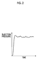
- FIG. 2 is a view illustrating fluctuations of an injection pressure during injection from a cylinder by forward movement of a screw in a purge operation according to the embodiment.
- the fluctuations of the injection pressure are illustrated in an exaggerated manner in FIG. 2 .
- this injection pressure is substantially stabilized.
- the controller 90 monitors the injection pressure at the time of the forward movement of the screw 43, and determines a molten state of the molding material on the basis of the fluctuations of the injection pressure.
- the injection pressure is measurable by, for example, a pressure detector 47. Since the fluctuations of the injection pressure show the roughness and fineness of the molding material, determination of the molten state of the molding material becomes possible.
- the measurement of the injection pressure may be performed from the start of the forward movement of the screw 43 to the end of the forward movement. Although all measurement data may be used for the determination, only a portion of the measurement data may be used for the determination.
- the injection pressure used for the determination may be the data after a predetermined time.
- the injection pressure used for the determination may be the data after a predetermined time passes from the start of the forward movement of the screw 43, the data after the screw 43 reaches a predetermined position, the data after the injection pressure rises first and is then substantially stabilized, or the like. in these cases, since the roughness and fineness of the molding material appear markedly in the fluctuations of the injection pressure, determination precision can be improved.
- a criterion for determination of (2) is whether or not the range of fluctuations of the injection pressure from a reference value is equal to or lower than a threshold value.
- the range of fluctuations exceeds the threshold value, the momentary fluctuations of the injection pressure are large, and the roughness and fineness of the molding material appear markedly. Therefore, there is a concern that a portion of the molding material may be injected as unmelted from the injection unit 40.
- the range of fluctuations exceeds the threshold value, it is determined that the molten state of the molding material is bad.
- the momentary fluctuations of the injection pressure is small and it is determined that the molten state of the molding material is good.
- the reference value may be, for example, an average value of all the data used for the determination, or a moving average deviation of the latest data of all the data used for the determination.
- the moving average may be any of a simple moving average, a load moving average, and an index moving average.
- the controller 90 may acquire the fluctuations of the injection pressure at the time of the forward movement of the screw 43 in the purge operation as data used for drawing-up of the criteria for determination of the molten state of the molding material.
- the controller 90 matches the acquired fluctuations with the molten state of the molding material, and stores the matching results in the storage medium 92.
- the molten state of the molding material can be determined by visual inspection, inspection of quality, and the like after solidification of the molding material.
- the results may be stored in the controller 90 via an operating unit or the like that receives an input operation performed by a user.
- the controller 90 may change the molding conditions, such as the set number of rotations of the screw 43, and the set temperature of the cylinder 41, thereby acquire a lot of data.
- the controller 90 may change the settings of the molding conditions on the basis of the results of determination of the molten state of the molding material. For example, the controller 90 may change at least one of the set number of rotations of the screw 43 and the set temperature of the cylinder 41 on the basis of the results of determination of the molten state of the molding material.
- the set number of rotations of the screw 43 may be changed in its decreasing direction. Since a speed at which the molding material is fed forward becomes low and the heating time of the molding material becomes long, the molten state of the molding material is improved. Additionally, in a case where the molten state of the molding material is bad, the set temperature of the cylinder 41 may be changed in its increasing direction. Even in this case, the molten state of the molding material is naturally improved.
- the controller 90 of the above embodiment determines the molten state of the molding material in two steps of good and bad
- the molten state may be determined in multiple steps of three or more steps.
- the criteria for determination may also be drawn up in multiple steps.
- the controller 90 may change the settings of molding conditions with a change width according to steps.
Landscapes
- Engineering & Computer Science (AREA)
- Manufacturing & Machinery (AREA)
- Mechanical Engineering (AREA)
- Injection Moulding Of Plastics Or The Like (AREA)
Abstract
Description
- Priority is claimed to Japanese Patent Application No.
2015-111694, filed June 1, 2015 - A certain embodiment of the present invention relates to an injection molding machine.
- Inject ion molding machines have an injection unit that fills a cavity space of a mold unit with a molding material. The injection unit has a cylinder that heats the molding material, and a screw that is rotatably disposed within the cylinder. The screw has a rotating shaft, and a spiral flight that protrudes from an outer periphery of the rotating shaft. A spiral groove is formed by the flight, and the molding material is supplied to an upstream part of the groove. The injection unit feeds the molding material from an upstream side to a downstream side along the groove by rotating the rotating shaft. The molding material is gradually melted by the heat from the cylinder while being fed to the downstream side (for example, refer to Japanese Unexamined Patent Application Publication No.
2000-185342 - In the related art, a molten state of the molding material is unknown.
- The invention has been made in view of the above problems, and a main object thereof is to provide an injection molding machine in which a molten state of a molding material can be ascertained.
- In order to solve the above problems, according to an aspect of the invention, there is provided an injection molding machine including an injection unit including a cylinder that heats a molding material, and an injection member that is disposed within the cylinder so as to be movable forward and backward; and a monitoring unit that monitors the injection pressure of the molding material injected from the cylinder by forward movement of the injection member. The monitoring unit determines a molten state of the molding material on the basis of fluctuations of the injection pressure at the time of the forward movement of the injection member.
- According to the aspect of the invention, an injection molding machine in which a molten state of a molding material can be ascertained is provided.
-
-
FIG. 1 is a view illustrating an injection molding machine according to an embodiment. -
FIG. 2 is a view illustrating fluctuations of an injection pressure during injection from a cylinder by forward movement of a screw in a purge operation according to the embodiment. - An embodiment for carrying out the invention will be described below with reference to the drawings, the same or corresponding components being designated by the same or corresponding reference signs, and the description thereof being omitted.
-
FIG. 1 is a view illustrating an injection molding machine according to an embodiment. An injection molding machine has aninjection unit 40 and acontroller 90. - The
injection unit 40 is made to be movable forward and backward with respect to a mold unit 30. Theinjection unit 40 is touched on the mold unit 30, and fills acavity space 34 of the mold unit 30 with a molding material. The mold unit 30 is constituted of astationary mold 32 and amovable mold 33. By moving themovable mold 33 forward and backward with respect to thestationary mold 32, mold closing, mold clamping, and mold opening of the mold unit 30 are performed. Thecavity space 34 is formed between thestationary mold 32 and themovable mold 33 in a mold clamped state. A molding product is obtained by the molding material filled within thecavity space 34 being hardened. Thereafter, mold opening of the mold unit 30 is performed and the molding product is pushed out from the mold unit 30. - The
injection unit 40 has, for example, acylinder 41, anozzle 42, ascrew 43, a plasticizingmotor 45, aninjection motor 46, and apressure detector 47. Hereinafter, a description will be made with a movement direction (leftward direction inFIG. 1 ) of thescrew 43 during filling being as the front, and a movement direction (rightward direction ofFIG. 1 ) of thescrew 43 during plasticizing being as the rear. - The
cylinder 41 heats the molding material supplied from asupply port 41a. Thesupply port 41a is formed at a rear part of thecylinder 41. - A heating source H, such as a heater, is provided at an outer periphery of the
cylinder 41. A plurality of the heating sources H are provided in an axial direction of thecylinder 41. Thecontroller 90 independently controls the plurality of heating sources H so that a temperature distribution in the axial direction of thecylinder 41 becomes a set temperature distribution. - The temperature of the
cylinder 41 is measured by a thermometer T, such as a thermocouple. A plurality of the thermometers T are provided in the axial direction of thecylinder 41, and output each measurement temperature to thecontroller 90. Thecontroller 90 controls the heating sources H so that the deviations between the measurement temperature and a set temperature become zero. - The
nozzle 42 is provided at a front end of thecylinder 41, and is pressed against the mold unit 30. - The
screw 43 is disposed within thecylinder 41 so as to be rotatable and movable forward and backward. Thescrew 43 has a rotatingshaft 431, and aspiral flight 432 that protrudes from an outer periphery of the rotatingshaft 431. Aspiral groove 433 is formed by theflight 432, and the molding material is fed from an upstream side (a right side in the drawing) to a downstream side (a left side in the drawing) along thegroove 433. Thescrew 43 corresponds to an injection member set forth in the claims. - In addition, the
screw 43 may further has a subflight that partitions thegroove 433 formed by theflight 432. - The
screw 43 has a first section Z1, a second section Z2, and a third section Z3 in this order from the upstream side toward the downstream side. The first section Z1 is a section where the solid phase of the molding material is present. The second section Z2 is a section where both of a solid phase and a liquid phase of the molding material are present. The third section Z3 is a section where the liquid phase of the molding material is present. - The
groove 433 is deep in the first section Z1, is shallow in the third section Z3, and is shallower from the upstream side to the downstream side in the second section Z2. In this case, the first section Z1 is also referred to as a feeding zone, the second section Z2 is also referred to as a compression zone, and the third section Z3 are also referred to as a metering zone. - In addition, the depth of the
groove 433 may be constant. - The plasticizing
motor 45 rotates thescrew 43, thereby feeding the molding material forward along a spiral groove of thescrew 43. The molding material is gradually melted by the heat from thecylinder 41 while being fed forward. When the liquid molding material is fed to the front of thescrew 43 and accumulated at the front part of thecylinder 41, thescrew 43 is movedbackward. - The
injection motor 46 moves thescrew 43 forward and backward. Theinjection motor 46 moves thescrew 43 forward, thereby filling thecavity space 34 of the mold unit 30 with the liquid molding material accumulated in front of thescrew 43. Thereafter, theinjection motor 46 pushes thescrew 43 forward, and applies a pressure to the molding material within thecavity space 34. An insufficient molding material can be replenished. A motion conversion mechanism that converts the rotational motion of theinjection motor 46 into a linear motion of thescrew 43 is provided between theinjection motor 46 and thescrew 43. - The
pressure detector 47 is disposed, for example, between theinjection motor 46 and thescrew 43, and detects a pressure that thescrew 43 receives from the molding material, a back pressure to thescrew 43, and the like. The pressure that thescrew 43 receives from the molding material is equivalent to a pressure acting on the molding material from thescrew 43. - The
controller 90 has a central processing unit (CPU) 91, and astorage medium 92, such as a memory. Thecontroller 90 makes theCPU 91 execute a program stored in thestorage medium 92, thereby controlling theinjection unit 40 and the like. Thecontroller 90 corresponds to a monitoring unit set forth in the claims. In addition, the monitoring unit may be provided separately from thecontroller 90. - The
controller 90 performs a molding operation of performing a series of steps, such as a filling step, a holding pressure step, and a cooling step, thereby manufacturing a molding product. Thecontroller 90 performs a cycle operation of repeating the series of steps, thereby repeatedly manufacturing a molding product. A plasticizing step maybe performed during the cooling step for shortening of a molding cycle. - In the filling step, the
injection motor 46 is driven to move thescrew 43 forward at a setting speed, and the inside of the mold unit 30 is filled with the liquid molding material accumulated in front of thescrew 43. The position and the speed of thescrew 43 are detected by, for example, anencoder 46a of theinjection motor 46. If the position of thescrew 43 reaches a predetermined position, switching (so-called V/P switching) from the filling step to the holding pressure step is performed. - In addition, after the position of the
screw 43 reaches the predetermined position in a filling step, thescrew 43 may be stopped at the predetermined position, and then, the V/P switching may be performed. Immediately before the V/P switching, the slow-speed forward movement or the slow-speed backward movement of thescrew 43 may be performed instead of the stop of thescrew 43. - In the holding pressure step, the
injection motor 46 is driven to push thescrew 43 forward with a setting pressure, and a pressure is applied to the molding material within the mold unit 30. An insufficient molding material can be replenished. The pressure of the molding material is detected by, for example, thepressure detector 47. A cooling step is started after the holding pressure step. In the cooling step, hardening of the molding material within thecavity space 34 is performed. The plasticizing step may be performed during the cooling step. - In the plasticizing step, the
plasticizing motor 45 is driven to rotate thescrew 43 at a set number of rotations, and feeds the molding material forward along the spiral groove of thescrew 43. The molding material is gradually melted with this feeding. When the liquid molding material is fed to the front of thescrew 43 and accumulated at the front part of thecylinder 41, thescrew 43 is moved backward. The number of rotations of thescrew 43 is detected by, for example, anencoder 45a of theplasticizing motor 45. - In the plasticizing step, the
injection motor 46 is driven to apply a set back pressure to thescrew 43 in order to limit a sudden backward movement of thescrew 43. The set back pressure to thescrew 43 is detected by, for example, thepressure detector 47. The plasticizing step is completed if thescrew 43 moves backward to a predetermined position and a predetermined amount of the molding material is accumulated in front of thescrew 43. - In addition, although the
injection unit 40 of the present embodiment is of an in-line screw type, the injection unit may be of apreplasticization type or the like. Thepreplasticization type injection unit supplies a molding material melted within a plasticizing cylinder to an injection cylinder, and injects the molding material into the mold unit from the injection cylinder. The screw is disposed inside the plasticizing cylinder so as to be rotatable or rotatable and movable forward and backward, and a plunger is disposed within the injection cylinder so as to be movable forward and backward. In this case, the injection cylinder corresponds to a cylinder set forth in the claims, and the plunger corresponds to an injection member set forth in the claims. - Meanwhile, a purge operation is performed at the time of warming-up, at the time of replacement of the molding material, and the like. The purge operation is performed in a state where the
injection unit 40 is separated from the mold unit 30, and includes an operation corresponding to the plasticizing step and an operation corresponding to the filling step. In the operation corresponding to the plasticizing step, the molding material is accumulated in front of thescrew 43 by rotating thescrew 43 at a set number of rotations. Thescrew 43 is moved backward along with this. In this case, an opening and closing mechanism (not illustrated) may block thenozzle 42. Meanwhile, in the operation corresponding to the filling step, the liquid molding material accumulated in front of thescrew 43 is injected from thecylinder 41 by moving thescrew 43 forward at a setting speed. In this case, the opening and closing mechanism opens thenozzle 42. -
FIG. 2 is a view illustrating fluctuations of an injection pressure during injection from a cylinder by forward movement of a screw in a purge operation according to the embodiment. The fluctuations of the injection pressure are illustrated in an exaggerated manner inFIG. 2 . As illustrated inFIG. 2 , once the injection pressure rises, this injection pressure is substantially stabilized. - Since roughness and fineness are in the molding material if unmelted grains are included in the molding material injected from the
cylinder 41, the injection pressure fluctuates momentarily. Meanwhile, if the molding material injected from thecylinder 41 is sufficiently melted and is uniform, momentary fluctuations of the injection pressure hardly occur. - Hence, the
controller 90 monitors the injection pressure at the time of the forward movement of thescrew 43, and determines a molten state of the molding material on the basis of the fluctuations of the injection pressure. The injection pressure is measurable by, for example, apressure detector 47. Since the fluctuations of the injection pressure show the roughness and fineness of the molding material, determination of the molten state of the molding material becomes possible. - The measurement of the injection pressure may be performed from the start of the forward movement of the
screw 43 to the end of the forward movement. Although all measurement data may be used for the determination, only a portion of the measurement data may be used for the determination. The injection pressure used for the determination may be the data after a predetermined time. For example, the injection pressure used for the determination may be the data after a predetermined time passes from the start of the forward movement of thescrew 43, the data after thescrew 43 reaches a predetermined position, the data after the injection pressure rises first and is then substantially stabilized, or the like. in these cases, since the roughness and fineness of the molding material appear markedly in the fluctuations of the injection pressure, determination precision can be improved. - Criteria for determination include, for example, criteria for determination of the following (1) to (2). These criteria for determination may be independently used, or may be used in combination.
- A criterion for determination of (1) is whether or not the rate of increase in the injection pressure falls within a predetermined range. In a case where the rate of increase in the injection pressure does not fall within the predetermined range, the momentary fluctuations of the injection pressure are large and the roughness and fineness of the molding material appear markedly. Therefore, there is a concern that a portion of the molding material may be injected as unmelted from the
injection unit 40. Hence, in a case where the rate of increase in the injection pressure does not fall within the predetermined range, it is determined that the molten state of the molding material is bad. On the other hand, in a case where the rate of increase in the injection pressure falls within the predetermined range, the momentary fluctuations of the injection pressure is small, and it is determined that the molten state of the molding material is good. - A criterion for determination of (2) is whether or not the range of fluctuations of the injection pressure from a reference value is equal to or lower than a threshold value. In a case where the range of fluctuations exceeds the threshold value, the momentary fluctuations of the injection pressure are large, and the roughness and fineness of the molding material appear markedly. Therefore, there is a concern that a portion of the molding material may be injected as unmelted from the
injection unit 40. Hence, in a case where the range of fluctuations exceeds the threshold value, it is determined that the molten state of the molding material is bad. On the other hand, in a case where the range of fluctuations is equal to or lower than the threshold value, the momentary fluctuations of the injection pressure is small and it is determined that the molten state of the molding material is good. Here, the reference value may be, for example, an average value of all the data used for the determination, or a moving average deviation of the latest data of all the data used for the determination. The moving average may be any of a simple moving average, a load moving average, and an index moving average. - In this case, the
controller 90 may determine the molten state of the molding material on the basis of the fluctuations of the injection pressure at the time of the forward movement of thescrew 43 in the purge operation. By performing the determination at the time of the purge operation, settings of molding conditions are possible before the start of the molding operation. - In addition, the
controller 90 may determine the molten state of the molding material on the basis of the fluctuations of the injection pressure at the time of the forward movement of thescrew 43 in the molding operation. The yield of a molding product can be improved by performing the determination at the time of the molding operation. - The
controller 90 may acquire the fluctuations of the injection pressure at the time of the forward movement of thescrew 43 in the purge operation as data used for drawing-up of the criteria for determination of the molten state of the molding material. Thecontroller 90 matches the acquired fluctuations with the molten state of the molding material, and stores the matching results in thestorage medium 92. The molten state of the molding material can be determined by visual inspection, inspection of quality, and the like after solidification of the molding material. The results may be stored in thecontroller 90 via an operating unit or the like that receives an input operation performed by a user. Thecontroller 90 may change the molding conditions, such as the set number of rotations of thescrew 43, and the set temperature of thecylinder 41, thereby acquire a lot of data. Thecontroller 90 obtains, for example, a predetermined range of the criterion for determination of the above (1), the threshold value of the criterion for determination of the above (2), and the like on the basis of these kinds of memory. Hence, the criteria for determination can be drawn up during the purge operation, and the criteria for determination can be drawn up before the molding operation. Using the drawn-up criteria for determination, thecontroller 90 may determine the molten state of the molding material in another purge operation, or may determine the molten state of the molding material in the molding operation. In addition, although thecontroller 90 takes above data by performing the purge operation, the above datamaybe taken by performing the molding operation in a tentative way. - The
controller 90 may output an alarm on the basis of results of determination of the molten state of the molding material. An alarm is output in a case where the molten state of the molding material is bad, and an alarm is not output in a case where the molten state of the molding material is good. The output of an alarm may be performed by the display of an image, the output of sound, and the like. - The
controller 90 may change the settings of the molding conditions on the basis of the results of determination of the molten state of the molding material. For example, thecontroller 90 may change at least one of the set number of rotations of thescrew 43 and the set temperature of thecylinder 41 on the basis of the results of determination of the molten state of the molding material. - In a case where the molten state of the molding material is bad, the set number of rotations of the
screw 43 may be changed in its decreasing direction. Since a speed at which the molding material is fed forward becomes low and the heating time of the molding material becomes long, the molten state of the molding material is improved. Additionally, in a case where the molten state of the molding material is bad, the set temperature of thecylinder 41 may be changed in its increasing direction. Even in this case, the molten state of the molding material is naturally improved. - Meanwhile, in a case where the molten state of the molding material is good, the settings of the molding conditions do not need to be changed, but may be changed. In a case where the molten state of the molding material is good, the set number of rotations of the
screw 43 may be changed in its increasing direction within a favorable range. The molding cycle can be shortened. Additionally, in a case where the molten state of the molding material is good, the set temperature of thecylinder 41 may be changed in its decreasing direction within a favorable range. The load on the heating sources H can be reduced. - The set number of rotations of the
screw 43 may be set to be as large as possible in a range where the molten state of the molding material is good. The set number of rotations of thescrew 43 is determined taking the time of the cooling step, and the like into consideration. - Additionally, the set temperature of the
cylinder 41 may be set to be as small as possible in a range where the molten state of the molding material is good. The set temperature of thecylinder 41 is determined taking the set number of rotations of thescrew 43, and the like, into consideration. - Although the embodiment of the injection unit has been described above, the invention is not limited to the above-described embodiment, and various alterations and improvements can be made within the concept of the invention described in the claims.
- For example, although the
controller 90 of the above embodiment determines the molten state of the molding material in two steps of good and bad, the molten state may be determined in multiple steps of three or more steps. In this case, the criteria for determination may also be drawn up in multiple steps. Additionally, in this case, thecontroller 90 may change the settings of molding conditions with a change width according to steps.
Claims (8)
- An injection molding machine comprising:an injection unit including a cylinder that heats a molding material, and an injection member that is disposed within the cylinder so as to be movable forward and backward; anda monitoring unit that monitors the injection pressure of the molding material injected from the cylinder by forward movement of the injection member,wherein the monitoring unit determines a molten state of the molding material on the basis of fluctuations of the injection pressure at the time of the forward movement of the injection member.
- The injection molding machine according to Claim 1,wherein the monitoring unit determines the molten state of the molding material on the basis of the rate of increase in the injection pressure at the time of the forward movement of the injection member.
- The injection molding machine according to Claim 1 or 2,wherein the monitoring unit determines the molten state of the molding material on the basis of a range of fluctuations from a reference value of the injection pressure at the time of the forward movement of the injection member.
- The injection molding machine according to any one of Claims 1 to 3,wherein the monitoring unit determines the molten state of the molding material on the basis of the fluctuations of the injection pressure at the time of the forward movement of the injection member in a purge operation.
- The injection molding machine according to any one of Claims 1 to 4,wherein the monitoring unit determines the molten state of the molding material on the basis of the fluctuations of the injection pressure at the time of the forward movement of the injection member in a molding operation.
- The injection molding machine according to any one of Claims 1 to 5,wherein the monitoring unit acquires the fluctuations of the injection pressure at the time of the forward movement of the injection member in a purge operation as data used for drawing-up of criteria for determination of the molten state.
- The injection molding machine according to any one of Claims 1 to 6,wherein the monitoring unit outputs an alarm on the basis of results of determinations of the molten state.
- The injection molding machine according to any one of Claims 1 to 7,wherein the monitoring unit changes settings of molding conditions on the basis of results of determination of the molten state.
Applications Claiming Priority (1)
| Application Number | Priority Date | Filing Date | Title |
|---|---|---|---|
| JP2015111694A JP6625349B2 (en) | 2015-06-01 | 2015-06-01 | Injection molding machine |
Publications (2)
| Publication Number | Publication Date |
|---|---|
| EP3100841A1 true EP3100841A1 (en) | 2016-12-07 |
| EP3100841B1 EP3100841B1 (en) | 2018-05-02 |
Family
ID=56068780
Family Applications (1)
| Application Number | Title | Priority Date | Filing Date |
|---|---|---|---|
| EP16170829.2A Not-in-force EP3100841B1 (en) | 2015-06-01 | 2016-05-23 | Injection molding machine |
Country Status (3)
| Country | Link |
|---|---|
| EP (1) | EP3100841B1 (en) |
| JP (1) | JP6625349B2 (en) |
| CN (1) | CN106182653B (en) |
Cited By (3)
| Publication number | Priority date | Publication date | Assignee | Title |
|---|---|---|---|---|
| WO2019185594A1 (en) * | 2018-03-27 | 2019-10-03 | Kraussmaffei Technologies Gmbh | Method for the automatic process monitoring and process diagnosis of a piece-based process (batch production), in particular an injection-molding process, and machine that performs the process or set of machines that performs the process |
| CN113165232A (en) * | 2018-11-21 | 2021-07-23 | 耐克创新有限合伙公司 | Systems and methods for forming sole structures |
| CN113165231A (en) * | 2018-11-21 | 2021-07-23 | 耐克创新有限合伙公司 | System and method for foaming process |
Families Citing this family (4)
| Publication number | Priority date | Publication date | Assignee | Title |
|---|---|---|---|---|
| JP6910825B2 (en) * | 2017-03-28 | 2021-07-28 | 住友重機械工業株式会社 | Injection molding machine and evaluation system |
| JP6773742B2 (en) * | 2018-10-02 | 2020-10-21 | ファナック株式会社 | Injection molding machine and screw control method for injection molding machine |
| JP2025073468A (en) * | 2023-10-26 | 2025-05-13 | 芝浦機械株式会社 | injection molding machine |
| CN117601376A (en) * | 2023-11-08 | 2024-02-27 | 浙江安胜科技股份有限公司 | An injection molding device and injection molding process for improving color stability |
Citations (6)
| Publication number | Priority date | Publication date | Assignee | Title |
|---|---|---|---|---|
| US3784657A (en) * | 1970-03-10 | 1974-01-08 | Pennwalt Corp | Time monitored process for controlling injection molding cycle |
| JPS6391220A (en) * | 1986-10-06 | 1988-04-21 | Sumitomo Heavy Ind Ltd | Control equipment of plasticization of injection molding machine |
| JP2000185342A (en) | 1998-10-13 | 2000-07-04 | Fanuc Ltd | Screw structure for injection molding machine |
| DE102005016618B3 (en) * | 2005-04-12 | 2006-09-28 | Battenfeld Gmbh | Determining melt homogeneity in injection molding machines, to establish constant conditions, involves discharging the melt into the open, determining the pressure curve and using this to obtain the temperature curve |
| US20090278274A1 (en) * | 2005-07-08 | 2009-11-12 | Christopher Bader | Method for Monitoring and/or Controlling the Melt Filling of at Least One Cavity |
| EP2583811A1 (en) * | 2011-10-18 | 2013-04-24 | ENGEL AUSTRIA GmbH | Method for quantifying process fluctuations in the injection process of a injection moulding machine |
Family Cites Families (4)
| Publication number | Priority date | Publication date | Assignee | Title |
|---|---|---|---|---|
| JPS59174332A (en) * | 1983-03-23 | 1984-10-02 | Toshiba Mach Co Ltd | Apparatus for monitoring pressure in injection step |
| JPH0330926A (en) * | 1989-06-27 | 1991-02-08 | Sodick Co Ltd | Method for controlling injection molding machine and system thereof |
| JP3170757B2 (en) * | 1990-08-31 | 2001-05-28 | 東芝機械株式会社 | Barrier screw |
| JPH0753405B2 (en) * | 1991-11-28 | 1995-06-07 | 花王株式会社 | METHOD AND DEVICE FOR CONTROLLING VARIATION OF RESIN FLOW PHYSICAL PROPERTY IN INJECTION MOLDING MACHINE |
-
2015
- 2015-06-01 JP JP2015111694A patent/JP6625349B2/en not_active Expired - Fee Related
-
2016
- 2016-05-23 EP EP16170829.2A patent/EP3100841B1/en not_active Not-in-force
- 2016-05-31 CN CN201610375128.5A patent/CN106182653B/en not_active Expired - Fee Related
Patent Citations (6)
| Publication number | Priority date | Publication date | Assignee | Title |
|---|---|---|---|---|
| US3784657A (en) * | 1970-03-10 | 1974-01-08 | Pennwalt Corp | Time monitored process for controlling injection molding cycle |
| JPS6391220A (en) * | 1986-10-06 | 1988-04-21 | Sumitomo Heavy Ind Ltd | Control equipment of plasticization of injection molding machine |
| JP2000185342A (en) | 1998-10-13 | 2000-07-04 | Fanuc Ltd | Screw structure for injection molding machine |
| DE102005016618B3 (en) * | 2005-04-12 | 2006-09-28 | Battenfeld Gmbh | Determining melt homogeneity in injection molding machines, to establish constant conditions, involves discharging the melt into the open, determining the pressure curve and using this to obtain the temperature curve |
| US20090278274A1 (en) * | 2005-07-08 | 2009-11-12 | Christopher Bader | Method for Monitoring and/or Controlling the Melt Filling of at Least One Cavity |
| EP2583811A1 (en) * | 2011-10-18 | 2013-04-24 | ENGEL AUSTRIA GmbH | Method for quantifying process fluctuations in the injection process of a injection moulding machine |
Cited By (8)
| Publication number | Priority date | Publication date | Assignee | Title |
|---|---|---|---|---|
| WO2019185594A1 (en) * | 2018-03-27 | 2019-10-03 | Kraussmaffei Technologies Gmbh | Method for the automatic process monitoring and process diagnosis of a piece-based process (batch production), in particular an injection-molding process, and machine that performs the process or set of machines that performs the process |
| CN111867806A (en) * | 2018-03-27 | 2020-10-30 | 克劳斯玛菲科技有限公司 | Method for automatic process monitoring and process diagnostics of part-based processes (batch manufacturing), in particular injection moulding processes, and a machine for carrying out said process or a machine assembly for carrying out said process |
| CN113165232A (en) * | 2018-11-21 | 2021-07-23 | 耐克创新有限合伙公司 | Systems and methods for forming sole structures |
| CN113165231A (en) * | 2018-11-21 | 2021-07-23 | 耐克创新有限合伙公司 | System and method for foaming process |
| US11491690B2 (en) | 2018-11-21 | 2022-11-08 | Nike, Inc. | System and methods for a foaming process |
| US11673358B2 (en) | 2018-11-21 | 2023-06-13 | Nike, Inc. | System and methods for forming a sole structure |
| US12220847B2 (en) | 2018-11-21 | 2025-02-11 | Nike, Inc. | Systems and methods for injection molding |
| US12552078B2 (en) | 2018-11-21 | 2026-02-17 | Nike, Inc. | System and methods for forming a sole structure |
Also Published As
| Publication number | Publication date |
|---|---|
| EP3100841B1 (en) | 2018-05-02 |
| JP2016221879A (en) | 2016-12-28 |
| CN106182653A (en) | 2016-12-07 |
| JP6625349B2 (en) | 2019-12-25 |
| CN106182653B (en) | 2019-04-05 |
Similar Documents
| Publication | Publication Date | Title |
|---|---|---|
| EP3100841B1 (en) | Injection molding machine | |
| EP3100840B1 (en) | Injection molding machine | |
| US9821498B2 (en) | Injection molding method and injection molding device | |
| JP5913062B2 (en) | Injection molding machine, injection molding system, and raw material metering device | |
| KR101521708B1 (en) | Injection molding machine | |
| KR20080100252A (en) | Injection Molding Machine | |
| KR102269352B1 (en) | Injection molding machine | |
| JP6289970B2 (en) | Injection molding machine, injection molding machine setting device, and injection molding machine setting method | |
| EP2700488B1 (en) | Injection molding machine | |
| TW201343364A (en) | Injection molding machine | |
| JP2018069627A (en) | Injection molding machine | |
| JP6054215B2 (en) | Injection molding machine and setting support device for injection molding machine | |
| CN116175917A (en) | Control device for injection molding machine, injection molding machine, control method and program for injection molding machine | |
| JP6058468B2 (en) | Injection molding machine and setting support device for injection molding machine | |
| JP5908384B2 (en) | Management method of injection molding machine and injection molding machine | |
| EP2644352B1 (en) | Injection molding machine with two cylinders | |
| EP3222403B1 (en) | Injection unit | |
| CN116669881A (en) | injection molding machine | |
| JP6385832B2 (en) | Injection molding machine | |
| KR101888736B1 (en) | Injection device | |
| JP2554938B2 (en) | Injection molding apparatus and injection molding method | |
| JP2024090802A (en) | Control device, injection molding device | |
| CN116745095A (en) | Injection molding machine, control device and control method of injection molding machine | |
| KR20170105719A (en) | Method for Controlling Injection Molding Machine And Injection Molding Machine |
Legal Events
| Date | Code | Title | Description |
|---|---|---|---|
| PUAI | Public reference made under article 153(3) epc to a published international application that has entered the european phase |
Free format text: ORIGINAL CODE: 0009012 |
|
| 17P | Request for examination filed |
Effective date: 20160523 |
|
| AK | Designated contracting states |
Kind code of ref document: A1 Designated state(s): AL AT BE BG CH CY CZ DE DK EE ES FI FR GB GR HR HU IE IS IT LI LT LU LV MC MK MT NL NO PL PT RO RS SE SI SK SM TR |
|
| AX | Request for extension of the european patent |
Extension state: BA ME |
|
| 17Q | First examination report despatched |
Effective date: 20161109 |
|
| GRAP | Despatch of communication of intention to grant a patent |
Free format text: ORIGINAL CODE: EPIDOSNIGR1 |
|
| INTG | Intention to grant announced |
Effective date: 20171121 |
|
| GRAS | Grant fee paid |
Free format text: ORIGINAL CODE: EPIDOSNIGR3 |
|
| GRAA | (expected) grant |
Free format text: ORIGINAL CODE: 0009210 |
|
| AK | Designated contracting states |
Kind code of ref document: B1 Designated state(s): AL AT BE BG CH CY CZ DE DK EE ES FI FR GB GR HR HU IE IS IT LI LT LU LV MC MK MT NL NO PL PT RO RS SE SI SK SM TR |
|
| REG | Reference to a national code |
Ref country code: GB Ref legal event code: FG4D |
|
| REG | Reference to a national code |
Ref country code: CH Ref legal event code: EP Ref country code: AT Ref legal event code: REF Ref document number: 994719 Country of ref document: AT Kind code of ref document: T Effective date: 20180515 |
|
| REG | Reference to a national code |
Ref country code: DE Ref legal event code: R096 Ref document number: 602016002707 Country of ref document: DE |
|
| REG | Reference to a national code |
Ref country code: IE Ref legal event code: FG4D |
|
| REG | Reference to a national code |
Ref country code: CH Ref legal event code: NV Representative=s name: SCHNEIDER FELDMANN AG PATENT- UND MARKENANWAEL, CH |
|
| REG | Reference to a national code |
Ref country code: NL Ref legal event code: MP Effective date: 20180502 |
|
| REG | Reference to a national code |
Ref country code: LT Ref legal event code: MG4D |
|
| PG25 | Lapsed in a contracting state [announced via postgrant information from national office to epo] |
Ref country code: FI Free format text: LAPSE BECAUSE OF FAILURE TO SUBMIT A TRANSLATION OF THE DESCRIPTION OR TO PAY THE FEE WITHIN THE PRESCRIBED TIME-LIMIT Effective date: 20180502 Ref country code: BG Free format text: LAPSE BECAUSE OF FAILURE TO SUBMIT A TRANSLATION OF THE DESCRIPTION OR TO PAY THE FEE WITHIN THE PRESCRIBED TIME-LIMIT Effective date: 20180802 Ref country code: SE Free format text: LAPSE BECAUSE OF FAILURE TO SUBMIT A TRANSLATION OF THE DESCRIPTION OR TO PAY THE FEE WITHIN THE PRESCRIBED TIME-LIMIT Effective date: 20180502 Ref country code: LT Free format text: LAPSE BECAUSE OF FAILURE TO SUBMIT A TRANSLATION OF THE DESCRIPTION OR TO PAY THE FEE WITHIN THE PRESCRIBED TIME-LIMIT Effective date: 20180502 Ref country code: NO Free format text: LAPSE BECAUSE OF FAILURE TO SUBMIT A TRANSLATION OF THE DESCRIPTION OR TO PAY THE FEE WITHIN THE PRESCRIBED TIME-LIMIT Effective date: 20180802 Ref country code: ES Free format text: LAPSE BECAUSE OF FAILURE TO SUBMIT A TRANSLATION OF THE DESCRIPTION OR TO PAY THE FEE WITHIN THE PRESCRIBED TIME-LIMIT Effective date: 20180502 |
|
| PG25 | Lapsed in a contracting state [announced via postgrant information from national office to epo] |
Ref country code: RS Free format text: LAPSE BECAUSE OF FAILURE TO SUBMIT A TRANSLATION OF THE DESCRIPTION OR TO PAY THE FEE WITHIN THE PRESCRIBED TIME-LIMIT Effective date: 20180502 Ref country code: LV Free format text: LAPSE BECAUSE OF FAILURE TO SUBMIT A TRANSLATION OF THE DESCRIPTION OR TO PAY THE FEE WITHIN THE PRESCRIBED TIME-LIMIT Effective date: 20180502 Ref country code: NL Free format text: LAPSE BECAUSE OF FAILURE TO SUBMIT A TRANSLATION OF THE DESCRIPTION OR TO PAY THE FEE WITHIN THE PRESCRIBED TIME-LIMIT Effective date: 20180502 Ref country code: GR Free format text: LAPSE BECAUSE OF FAILURE TO SUBMIT A TRANSLATION OF THE DESCRIPTION OR TO PAY THE FEE WITHIN THE PRESCRIBED TIME-LIMIT Effective date: 20180803 Ref country code: HR Free format text: LAPSE BECAUSE OF FAILURE TO SUBMIT A TRANSLATION OF THE DESCRIPTION OR TO PAY THE FEE WITHIN THE PRESCRIBED TIME-LIMIT Effective date: 20180502 |
|
| REG | Reference to a national code |
Ref country code: BE Ref legal event code: MM Effective date: 20180531 |
|
| PG25 | Lapsed in a contracting state [announced via postgrant information from national office to epo] |
Ref country code: SK Free format text: LAPSE BECAUSE OF FAILURE TO SUBMIT A TRANSLATION OF THE DESCRIPTION OR TO PAY THE FEE WITHIN THE PRESCRIBED TIME-LIMIT Effective date: 20180502 Ref country code: EE Free format text: LAPSE BECAUSE OF FAILURE TO SUBMIT A TRANSLATION OF THE DESCRIPTION OR TO PAY THE FEE WITHIN THE PRESCRIBED TIME-LIMIT Effective date: 20180502 Ref country code: PL Free format text: LAPSE BECAUSE OF FAILURE TO SUBMIT A TRANSLATION OF THE DESCRIPTION OR TO PAY THE FEE WITHIN THE PRESCRIBED TIME-LIMIT Effective date: 20180502 Ref country code: CZ Free format text: LAPSE BECAUSE OF FAILURE TO SUBMIT A TRANSLATION OF THE DESCRIPTION OR TO PAY THE FEE WITHIN THE PRESCRIBED TIME-LIMIT Effective date: 20180502 Ref country code: RO Free format text: LAPSE BECAUSE OF FAILURE TO SUBMIT A TRANSLATION OF THE DESCRIPTION OR TO PAY THE FEE WITHIN THE PRESCRIBED TIME-LIMIT Effective date: 20180502 Ref country code: DK Free format text: LAPSE BECAUSE OF FAILURE TO SUBMIT A TRANSLATION OF THE DESCRIPTION OR TO PAY THE FEE WITHIN THE PRESCRIBED TIME-LIMIT Effective date: 20180502 |
|
| REG | Reference to a national code |
Ref country code: DE Ref legal event code: R097 Ref document number: 602016002707 Country of ref document: DE |
|
| REG | Reference to a national code |
Ref country code: IE Ref legal event code: MM4A |
|
| PG25 | Lapsed in a contracting state [announced via postgrant information from national office to epo] |
Ref country code: SM Free format text: LAPSE BECAUSE OF FAILURE TO SUBMIT A TRANSLATION OF THE DESCRIPTION OR TO PAY THE FEE WITHIN THE PRESCRIBED TIME-LIMIT Effective date: 20180502 Ref country code: IT Free format text: LAPSE BECAUSE OF FAILURE TO SUBMIT A TRANSLATION OF THE DESCRIPTION OR TO PAY THE FEE WITHIN THE PRESCRIBED TIME-LIMIT Effective date: 20180502 |
|
| PLBE | No opposition filed within time limit |
Free format text: ORIGINAL CODE: 0009261 |
|
| STAA | Information on the status of an ep patent application or granted ep patent |
Free format text: STATUS: NO OPPOSITION FILED WITHIN TIME LIMIT |
|
| PG25 | Lapsed in a contracting state [announced via postgrant information from national office to epo] |
Ref country code: MC Free format text: LAPSE BECAUSE OF FAILURE TO SUBMIT A TRANSLATION OF THE DESCRIPTION OR TO PAY THE FEE WITHIN THE PRESCRIBED TIME-LIMIT Effective date: 20180502 Ref country code: LU Free format text: LAPSE BECAUSE OF NON-PAYMENT OF DUE FEES Effective date: 20180523 |
|
| 26N | No opposition filed |
Effective date: 20190205 |
|
| PG25 | Lapsed in a contracting state [announced via postgrant information from national office to epo] |
Ref country code: IE Free format text: LAPSE BECAUSE OF NON-PAYMENT OF DUE FEES Effective date: 20180523 Ref country code: FR Free format text: LAPSE BECAUSE OF NON-PAYMENT OF DUE FEES Effective date: 20180702 |
|
| PG25 | Lapsed in a contracting state [announced via postgrant information from national office to epo] |
Ref country code: SI Free format text: LAPSE BECAUSE OF FAILURE TO SUBMIT A TRANSLATION OF THE DESCRIPTION OR TO PAY THE FEE WITHIN THE PRESCRIBED TIME-LIMIT Effective date: 20180502 Ref country code: BE Free format text: LAPSE BECAUSE OF NON-PAYMENT OF DUE FEES Effective date: 20180531 |
|
| PG25 | Lapsed in a contracting state [announced via postgrant information from national office to epo] |
Ref country code: AL Free format text: LAPSE BECAUSE OF FAILURE TO SUBMIT A TRANSLATION OF THE DESCRIPTION OR TO PAY THE FEE WITHIN THE PRESCRIBED TIME-LIMIT Effective date: 20180502 |
|
| PG25 | Lapsed in a contracting state [announced via postgrant information from national office to epo] |
Ref country code: MT Free format text: LAPSE BECAUSE OF NON-PAYMENT OF DUE FEES Effective date: 20180523 |
|
| PG25 | Lapsed in a contracting state [announced via postgrant information from national office to epo] |
Ref country code: TR Free format text: LAPSE BECAUSE OF FAILURE TO SUBMIT A TRANSLATION OF THE DESCRIPTION OR TO PAY THE FEE WITHIN THE PRESCRIBED TIME-LIMIT Effective date: 20180502 |
|
| PG25 | Lapsed in a contracting state [announced via postgrant information from national office to epo] |
Ref country code: PT Free format text: LAPSE BECAUSE OF FAILURE TO SUBMIT A TRANSLATION OF THE DESCRIPTION OR TO PAY THE FEE WITHIN THE PRESCRIBED TIME-LIMIT Effective date: 20180502 |
|
| PG25 | Lapsed in a contracting state [announced via postgrant information from national office to epo] |
Ref country code: HU Free format text: LAPSE BECAUSE OF FAILURE TO SUBMIT A TRANSLATION OF THE DESCRIPTION OR TO PAY THE FEE WITHIN THE PRESCRIBED TIME-LIMIT; INVALID AB INITIO Effective date: 20160523 Ref country code: MK Free format text: LAPSE BECAUSE OF NON-PAYMENT OF DUE FEES Effective date: 20180502 Ref country code: CY Free format text: LAPSE BECAUSE OF FAILURE TO SUBMIT A TRANSLATION OF THE DESCRIPTION OR TO PAY THE FEE WITHIN THE PRESCRIBED TIME-LIMIT Effective date: 20180502 |
|
| REG | Reference to a national code |
Ref country code: AT Ref legal event code: UEP Ref document number: 994719 Country of ref document: AT Kind code of ref document: T Effective date: 20180502 |
|
| PG25 | Lapsed in a contracting state [announced via postgrant information from national office to epo] |
Ref country code: IS Free format text: LAPSE BECAUSE OF FAILURE TO SUBMIT A TRANSLATION OF THE DESCRIPTION OR TO PAY THE FEE WITHIN THE PRESCRIBED TIME-LIMIT Effective date: 20180902 |
|
| REG | Reference to a national code |
Ref country code: CH Ref legal event code: PFA Owner name: SUMITOMO HEAVY INDUSTRIES, LTD., JP Free format text: FORMER OWNER: SUMITOMO HEAVY INDUSTRIES, LTD., JP |
|
| GBPC | Gb: european patent ceased through non-payment of renewal fee |
Effective date: 20200523 |
|
| PG25 | Lapsed in a contracting state [announced via postgrant information from national office to epo] |
Ref country code: GB Free format text: LAPSE BECAUSE OF NON-PAYMENT OF DUE FEES Effective date: 20200523 |
|
| PGFP | Annual fee paid to national office [announced via postgrant information from national office to epo] |
Ref country code: AT Payment date: 20210426 Year of fee payment: 6 Ref country code: CH Payment date: 20210519 Year of fee payment: 6 |
|
| REG | Reference to a national code |
Ref country code: CH Ref legal event code: PL |
|
| REG | Reference to a national code |
Ref country code: AT Ref legal event code: MM01 Ref document number: 994719 Country of ref document: AT Kind code of ref document: T Effective date: 20220523 |
|
| PG25 | Lapsed in a contracting state [announced via postgrant information from national office to epo] |
Ref country code: LI Free format text: LAPSE BECAUSE OF NON-PAYMENT OF DUE FEES Effective date: 20220531 Ref country code: CH Free format text: LAPSE BECAUSE OF NON-PAYMENT OF DUE FEES Effective date: 20220531 Ref country code: AT Free format text: LAPSE BECAUSE OF NON-PAYMENT OF DUE FEES Effective date: 20220523 |
|
| PGFP | Annual fee paid to national office [announced via postgrant information from national office to epo] |
Ref country code: DE Payment date: 20240328 Year of fee payment: 9 |
|
| REG | Reference to a national code |
Ref country code: DE Ref legal event code: R119 Ref document number: 602016002707 Country of ref document: DE |
|
| PG25 | Lapsed in a contracting state [announced via postgrant information from national office to epo] |
Ref country code: DE Free format text: LAPSE BECAUSE OF NON-PAYMENT OF DUE FEES Effective date: 20251202 |