EP3100837B1 - Zementartige material struktur mit sensoren, deren herstellungsverfahren und deren betriebsverfahren - Google Patents
Zementartige material struktur mit sensoren, deren herstellungsverfahren und deren betriebsverfahren Download PDFInfo
- Publication number
- EP3100837B1 EP3100837B1 EP16020173.7A EP16020173A EP3100837B1 EP 3100837 B1 EP3100837 B1 EP 3100837B1 EP 16020173 A EP16020173 A EP 16020173A EP 3100837 B1 EP3100837 B1 EP 3100837B1
- Authority
- EP
- European Patent Office
- Prior art keywords
- sensing elements
- cementitious material
- sensors
- substrate
- cementitious
- Prior art date
- Legal status (The legal status is an assumption and is not a legal conclusion. Google has not performed a legal analysis and makes no representation as to the accuracy of the status listed.)
- Active
Links
Images

Classifications
-
- G—PHYSICS
- G08—SIGNALLING
- G08B—SIGNALLING SYSTEMS, e.g. PERSONAL CALLING SYSTEMS; ORDER TELEGRAPHS; ALARM SYSTEMS
- G08B5/00—Visible signalling systems, e.g. visible personal calling systems or remote indication of seats occupied
- G08B5/22—Visible signalling systems, e.g. visible personal calling systems or remote indication of seats occupied using electric transmission; using electromagnetic transmission
- G08B5/36—Visible signalling systems, e.g. visible personal calling systems or remote indication of seats occupied using electric transmission; using electromagnetic transmission using visible light sources
-
- A—HUMAN NECESSITIES
- A61—MEDICAL OR VETERINARY SCIENCE; HYGIENE
- A61B—DIAGNOSIS; SURGERY; IDENTIFICATION
- A61B5/00—Measuring for diagnostic purposes; Identification of persons
- A61B5/02—Detecting, measuring or recording for evaluating the cardiovascular system, e.g. pulse, heart rate, blood pressure or blood flow
- A61B5/024—Measuring pulse rate or heart rate
- A61B5/02405—Determining heart rate variability
-
- A—HUMAN NECESSITIES
- A61—MEDICAL OR VETERINARY SCIENCE; HYGIENE
- A61B—DIAGNOSIS; SURGERY; IDENTIFICATION
- A61B5/00—Measuring for diagnostic purposes; Identification of persons
- A61B5/02—Detecting, measuring or recording for evaluating the cardiovascular system, e.g. pulse, heart rate, blood pressure or blood flow
- A61B5/024—Measuring pulse rate or heart rate
- A61B5/02416—Measuring pulse rate or heart rate using photoplethysmograph signals, e.g. generated by infrared radiation
-
- B—PERFORMING OPERATIONS; TRANSPORTING
- B28—WORKING CEMENT, CLAY, OR STONE
- B28B—SHAPING CLAY OR OTHER CERAMIC COMPOSITIONS; SHAPING SLAG; SHAPING MIXTURES CONTAINING CEMENTITIOUS MATERIAL, e.g. PLASTER
- B28B23/00—Arrangements specially adapted for the production of shaped articles with elements wholly or partly embedded in the moulding material; Production of reinforced objects
- B28B23/0031—Arrangements specially adapted for the production of shaped articles with elements wholly or partly embedded in the moulding material; Production of reinforced objects with product identification means, e.g. labels on test products or integrated circuit tags inside products RFID
-
- G—PHYSICS
- G08—SIGNALLING
- G08B—SIGNALLING SYSTEMS, e.g. PERSONAL CALLING SYSTEMS; ORDER TELEGRAPHS; ALARM SYSTEMS
- G08B3/00—Audible signalling systems, e.g. audible personal calling systems
- G08B3/10—Audible signalling systems, e.g. audible personal calling systems using electric transmission; using electromagnetic transmission
Definitions
- the present invention relates to the field of construction, involving knowledge of building materials and sensors technologies. More specifically, it involves cementitious materials and waterproofing materials, among others, as well as different technologies of contact or proximity sensors. The intersection of these technologic fields allows achieving constructive structures with different shapes, functions and dimensions, which interact with external elements.
- Said cementitious materials are suitable for any kind of constructions, such as construction or rehabilitation, either inside or outside, of buildings, roads, street furniture, among others.
- the object of the invention also relates to the development of sensors suitable for interacting with human users.
- the present invention aims to introduce interactivity in cementitious material structures, through the integration of sensors during the concreting process. These structures have application in the construction/rehabilitation of buildings, in highways, street furniture, hospital facilities, among others.
- the closest antecedents of the present invention are found in the internal parameter monitoring systems of constructive structures, for continuous monitoring purposes and, therefore, predictive maintenance.
- Such systems are intended to monitor the response of structures over time, either in the construction phase itself or during its lifetime, by placing sensors on the surface of the cementitious structures, by drilling the structure and by placing the sensors on the inside, or by placing the sensors inside during its construction.
- Patent application publication No. WO 2007025172A2 discloses a system for monitoring the healing process of concrete, in which devices with sensing and wireless communication capabilities are placed inside the concrete during concreting, allowing to monitor the temperature at different points inside the structure, while concrete is drying.
- Patent application publication No. CN 102255959A discloses a system in which devices with strain gauges and temperature sensors and having wireless communication capability are embedded in a concrete structure during concreting, so that they monitor parameters which allow to know the conservation state of the structure throughout its lifetime.
- WO 2006/138607 A2 discloses a cementitious material structure with sensors according to the preamble of claim 1.
- the present invention it was intended to monitor external parameters and not internal structure parameters. With this change, it is intended to obtain interaction with the outside of the structure, in solutions of interactivity with a human user.
- the configuration, the arrangement, the sensor type and other features are distinct from those known in prior art, in a way that sensors embedded into the cementitious structures can detect variables external to the structure.
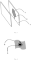
- Such a configuration is related to the sensing characteristics of the cementitious material structure. It is intended to measure a certain physical variable along the surface of the cementitious material structure, or part of it, thus defining an area over which the variable is detected, resulting in an adequate sensitive surface for monitoring a certain variable over the outer surface (4) of the structure.
- the cementitious material structure with sensors further includes a waterproofing material layer (3) covering the set of the plurality of sensing elements (1) and at least one substrate (2).
- the waterproofing material layer (3) allows the sensing elements (1) and the substrate (2), which typically are barely suitable to be involved with cementitious material, to be involved by it, thus allowing an external finishing only in cementitious materials while maintaining the robustness and reliability characteristics of the set of sensors.
- the waterproofing material layer (3) is therefore placed between the set of the plurality of sensing elements (1) together with the at least one substrate (2) and the cementitious material.
- the plurality of sensing elements (1) is printed on the substrate (2).
- the sensing elements (1) are printed on the substrate (2) by means of different possible techniques.
- Said sensitive surface is also involved in a waterproofing material, which encapsulates it in order to withstand the concreting process and throughout the lifetime of the structure, and involved in cementitious material, which provides a finishing that hides the plurality of sensing elements (1) and that corresponds to the outer surface (4) of the structure.
- This method further includes, for obtaining some of the configurations, the following step performed between steps a) and b):
- the present invention allows any cementitious material structure, for instance a concrete wall, becomes interactive with the outside, specifically incorporating a plurality of sensing elements (1) therein.
- the present invention comprises a configuration different from those of prior art and includes a cementitious material structure with sensors comprising a plurality of sensing elements (1) arranged on at least one substrate (2), and wherein the set of the plurality of sensing elements (1) with the at least one substrate (2) is involved in cementitious material.
- the set of the plurality of sensing elements (1) with the at least one substrate (2) included in the structure is covered by a waterproofing material layer (3) which separates it from the involving cementitious material.
- This waterproofing material layer (3) allows said set to be encapsulated so that it resists the concreting process and remains in operation during the lifetime of the structure.
- the set of the plurality of sensing elements (1), with the at least one substrate (2) and with the involving cementitious materials is called base assembly (14) .
- this structure has a configuration in which the plurality of sensing elements (1) is arranged on a surface substantially parallel to an outer surface (4) of the cementitious material structure with sensors.
- Such a configuration enables the alignment of the contact or outer interaction surface with the surface with sensors, thereby achieving the measurement of the variable along a particular area with sensors.
- the plurality of sensing elements (1) is printed on the at least one substrate (2).
- This embodiment is highly suitable to create cementitious material structures with sensors in situ and does not need a previous preparation of the sensing elements (1). Through different methods that are subject of the present invention, it is quite simple and versatile to create structures with sensors based on the cementitious material, making any structure a potential point of interaction.
- the at least one substrate (2) is a substrate of a non-cementitious material, such as a polymeric material, paper, derivatives of paper, ceramic or glass.
- a non-cementitious material such as a polymeric material, paper, derivatives of paper, ceramic or glass.
- the substrate (2) is polymer, it may consist of polyethylene terephthalate (PET) or polyethylene naphthalate (PEN).
- PET polyethylene terephthalate
- PEN polyethylene naphthalate
- the substrate (2) of a non-cementitious material thus consists of materials compatible with roller or sheets systems.
- These substrates present characteristics of dimensional stability, levelled surface, temperature resistance, namely till 160°C, and moisture resistance.
- the at least one substrate (2) consists in the cementitious material itself or in a micro concrete layer, and the printing surface of the plurality of sensing elements (1) in the cementitious material forms a substantially finite plane parallel to the outer surface (4) of the structure.
- This type of substrate (2) is shaped in a mold for filling with cementitious material (13).
- the sensors making part of the plurality of sensing elements (1) may consist in capacitive sensors, inductive sensors, sensors of electro-dermal activity, blood volume pulse, temperature, luminosity, sound, or a combination thereof, among others.
- the cementitious material structure with sensors additionally includes optical fibers arranged in such a way that one of the ends of each optical fiber is at the outer surface (4) of the structure and the other end is at the surface of each sensing element (1).
- This innovative configuration allows the sensing elements (1), which include a light source and a photodetector, to be encapsulated in the cementitious materials while simultaneously measuring BVP signals from the outside of the structure.
- the blood volume pulse (BVP) sensors of optoelectronic technology are not printed, but are rather prefabricated by one of the methods known in prior art.
- the present invention includes a configuration of the cementitious material structure with sensors in which the plurality of sensing elements (1) is arranged in a mesh, allowing interaction with the user or the external element through the detection by different sensing elements (1) of the mesh.
- the mesh configures a plane parallel to the outer surface (4).
- the cementitious material structure with sensors includes several planes parallel to each other and to the outer surface, having a plurality of sensing elements (1) and defining a three-dimensional mesh of sensing elements (1).
- the plurality of sensing elements (1) of the cementitious material structure with sensors is arranged in such a way that a central sensing element (5) is surrounded by at least two peripheral sensing elements (6), arranged on a line which is part of a plane parallel to the outer surface (4) of the cementitious material structure with sensors.
- the cementitious material structure with sensors includes at least four peripheral sensing elements (6) arranged in pairs in at least two perpendicular imaginary lines, which are part of a plane parallel to the outer surface (4) of the cementitious materials structure with sensors and intersect at midpoint of the central sensing element (5).
- the cementitious material structure with sensors allows the detection of the movements of the user over the surface with sensors, through individualized sensing elements (1).
- the present invention includes signal conditioning means (7), at least one microcontroller (8) and optionally local and/or remote communication means (9).
- the signal conditioning means (7) is connected to the plurality of sensing elements (1), being suitable to convert and adapt the signals from the sensing elements (1) into analogue/digital inputs of the at least one microcontroller (8), which processes the data and sends it via digital/analog communication to a wired/wireless central system.
- the cementitious material structure with sensors further includes, in one embodiment, at least one actuator element (10).
- the processing of the signals read by the integrated sensors allows generating different outputs in the at least one actuator element (10).
- the analysis of data from the plurality of sensing elements (1) and the consequent actuation on the at least one actuator element (10) may be carried out in situ or remotely, as the local and/or remote communication means (9) is suitable for connecting to a global management control system, which allows a customized interaction with the user.
- the at least one actuator element (10) consists of a LED or another type of light emitting means, and since in the present invention the electronics is integrated inside the concrete, the conduction of the light up to the outer surface (4) is made through a optical fiber which is also integrated into the cementitious material.
- the sensing elements (1) are, for example, blood volume pulse (BVP) sensors, wherein each fiber filament contacts, at one end, with the finger of the user, and with the light receiver or emitter located at the other end.
- BVP blood volume pulse
- the power supply of the electronic components embedded in the cementitious material structure with sensors consists of finite supply equipment - primary or secondary batteries - or direct connection to the mains, including in this case AC/DC conversion means.
- the power supply of the electronic elements set which is part of the cementitious material structure of the present invention is performed using a power cable connecting to power means (12), in any of the alternatives listed.
- these sets are laminated and/or coated with different materials in order to obtain electrical, mechanical and chemical protection after printing and before integration in the concrete structure.
- protective materials waterproof materials and materials with good mechanical and chemical resistance are considered in order to resist the concreting process of the concrete parts.
- the encapsulation of the printed sensors with these materials can be made through lamination, and/or heat sealing, and/or slot die, and/or doctor blade, and/or knife-over-edge, and/or screen printing, and/or spray, of a polymeric material curable by ultraviolet (UV) light and/or temperature.
- UV ultraviolet
- the manufacturing method of the present invention further includes the following step, performed after step a):
- step a) consists more specifically in printing a plurality of sensing elements (1) on at least one substrate (2).
- This step is suitable for all configurations of the cementitious material structure of the present invention, in which the sensing elements (1) are formed in situ , and is not suitable for the cases in which these are prefabricated by means of any methods known in prior art, and just integrated in situ on the at least one substrate (2).
- the printing step may consist of one of the following techniques, or combinations thereof:
- Encapsulation of the plurality of sensing elements (1) and the at least one substrate (2) may consist of a layer produced by lamination and/or coating with different materials - in order to obtain electrical, mechanical and chemical protection - after printing and before integration in the concrete structure and involvement with cementitious material.
- As protective materials waterproof materials and materials with good mechanical and chemical resistance are considered in order to resist the concreting process of the concrete parts.
- the encapsulation of the printed sensors with these materials can be made through lamination, and/or heat sealing, and/or slot die, and/or doctor blade, and/or knife-over-edge, and/or screen printing, and/or spray, of a polymeric material curable by ultraviolet (UV) light and/or temperature.
- UV ultraviolet
- the method includes more specifically the following steps:
- the method more specifically includes the following steps:
- the outer face is concreted according to the common procedure.
- the method further includes the following steps of phased concreting by means of layers:
- the method more specifically includes the following steps:
- sensing elements (1) consist of BVP sensing elements or other type of sensor whose monitored variable is related to light
- the sensing elements (1) are significantly close to the surface of the cementitious material structure with sensors, being covered with cementitious material and being at a depth of at least 0.5cm.
- the present invention further relates to a method of operation of the cementitious material structure with sensors, which includes the following steps:
- the waterproofing material (3) is a polymeric material.
- the at least one substrate (2) consists of a polymeric substrate.
- each sensing element (1) includes a sensing element extension (11) for connection to the other electronic elements with functions such as signal conditioning or signal processing.
- the cementitious material consists of concrete, mortar or micro concrete.
- the cementitious material consists of concrete with aesthetically appealing features, through using different colors/textures at least on the outer surface of the structure.
- the printing ink includes conductive materials such as silver, carbon, nickel, gold, platinum, polymeric materials such as PEDOT:PSS.
- the cementitious material structure with sensors includes optical fibers, allowing light emission at the concrete surface without affecting their surface characteristics and durability.
- optical fibers are inserted during the concreting process, and allow the light emission at the concrete surface without affecting their surface characteristics and durability.
- the cementitious material structure with sensors consists of a blood volume pulse (BVP) meter, in which the sensing elements (1) are BVP sensors and the at least one actuator element (10) is a light emitting diode (LED).
- BVP blood volume pulse
- the sensing elements (1) are BVP sensors
- the at least one actuator element (10) is a light emitting diode (LED).
- the light emitters and receivers are in direct contact with the surface of the external element, as for example the finger of a user (the extremity of the body where the signal measurement is usually held in conventional systems), the conduction of the light being accomplished using optical fiber as previously described.
- optical fibers are also carried out in order to generate dynamic effects by actuating the sensors through touch or proximity, at the concrete surface.
- This integration is performed through the rigorous positioning of the fiber in the contact surface, in order to capture the light reflected by the skin after exposure to the light emitted by the emitting fiber. This positioning is pre-molded and subsequently embedded in the final element, or properly positioned in the formwork before concreting.
- the manufacture of the cementitious material structure with sensors may include artistic and architectural finishing, coloring and various textures which make its appearance decorative and pleasing, facilitating their integration in existing structures without damage and adding aesthetic value to them, and giving maximum comfort to users.
- the present invention includes a configuration of the cementitious material structure with sensors where the plurality of sensing elements (1) is arranged in such a way that a central sensing element (5) is surrounded by at least two peripheral sensors elements (6), the sensing elements (1) consist of different electrodes of a conductive material, such as silver electrodes printed on rigid or flexible substrates, in which they are arranged according to a given geometry.
- Electrodes may be encapsulated to improve its strength and durability and to integrate them into the concrete, or materials can be used - preferably FR-4 - wherein the surface is coated with a conductive material (copper, silver, gold alloys, etc.). In these materials the electrodes are deployed in the geometrical arrangement necessary for the correct spatial signal detection (XYZ).
- Electrodes are at least connected to the signal conditioning means (7), which in turn is connected to the at least one microcontroller (8).
- the at least one microcontroller (8) is connected to the local and/or remote communication means (9).
- the cementitious material structure with sensors specifically includes the following elements:
- the ink used for printing includes conductive materials such as silver, carbon, nickel, gold or platinum, and polymeric materials such as PEDOT:PSS.
- conductive materials such as silver, carbon, nickel, gold or platinum
- polymeric materials such as PEDOT:PSS.
- rotogravure, or screen printing, or ink jet printing may be considered.
- the substrate (2) consists of a polymeric film based in polyethylene terephthalate (PET).
- PET polyethylene terephthalate
- the flexible polymeric substrates with printed sensors are integrated in the concrete during the concreting process.
- This integration is performed in a process called bilayer, in which the sensor is integrated between layers, thus constituting a high mechanical strength pre-molded element with sensors, which may later be embedded in walls, floors or other constructive elements (integrated during the concreting or in posterior coatings with mortars or screeds) or simply be directly exposed in similar supports.
- the cementitious material structure with sensors specifically includes the following elements:
- Piezoelectric sensors are identified for integration in the concrete. This type of sensors is encapsulated using epoxy resins, or others enabling the sensor protection against aggression of usage and concreting process.
- the integration of the sensing elements (1) in concrete is carried out using the bilayer process of concreting, where the sensing elements (1) are integrated between the two layers.
- the activation of the lighting means enables issuing a warning or message at the concrete surface.
- the control signal for feedback at the respective concrete slab, can be obtained through the use of wiring (physical interconnection between the concrete slabs) or alternatively via wireless communication, for example via radio frequency (RF), Wi-Fi, Bluetooth, ZigBee, or other type of wireless communications protocol.
- RF radio frequency
- the ZigBee is used.
- This wireless communication protocol involves the use of a transceiver integrated on each of the concrete substrates (2), allowing them to communicate with each other.
- the floor issuing security alerts to warn drivers of a pedestrian approaching in crossing zones is considered.
- the lighting means are integrated in the concrete part, by using optical fibers which conduct the emitted light to the concrete surface, ensuring their characteristics and durability.
- This set is remotely connected to a global management system for controlling the sensors remotely and customizing the type of interaction with the user and the way the actuator elements (10) act.
- This application includes the development of concrete parts with surface levelled by flattering and mechanical grinding after concreting, followed by sealing based on silanes-siloxanes and acrylic resins chemically compatible with the printing ink.
- the printing of sensors at the concrete surface can be carried out using inks with conductive materials, for example silver, carbon, nickel, gold, platinum, polymeric materials such as PEDOT:PSS.
- conductive materials for example silver, carbon, nickel, gold, platinum, polymeric materials such as PEDOT:PSS.
- the printing is performed by rotogravure, or screen printing, or ink jet.
- the sensor printed on the concrete surface is protected using waterproofing paints such as acrylic or silicate, or by means of micro concrete, mortar or compatible cementitious coating.
- the technology or the integration of printed sensors on polymeric substrates, or the so called traditional sensing of concrete allows developing interactive demonstrators for use as concrete parts in interactive street furniture, or flooring, or walls. These concrete parts can be applied to interactive games, through touch or proximity action.
- the cementitious material structure with sensors specifically includes the following elements:
- the integration of the BVP sensors in concrete is carried out by connecting the fibers ends embedded in the part.
- This scheme has several possible applications, among which the most common is the heartbeat measurement through detection of peaks in the photoplethysmogram, but there may also exists applications in the detection of heart rate variability (HRV), or in the evaluation studies of arterial resistance and aorta elasticity.
- HRV heart rate variability
- the BVP sensors have been used to extract some parameters of arousal during sleep.
- the data obtained are processed and monitored by a global management control system, and this data can be viewed remotely. If the values do not match the normal parameters (read values exceeding reference limits) an alert is sent to a user-defined contact.
Landscapes
- Health & Medical Sciences (AREA)
- Engineering & Computer Science (AREA)
- Physics & Mathematics (AREA)
- Life Sciences & Earth Sciences (AREA)
- Cardiology (AREA)
- Surgery (AREA)
- General Health & Medical Sciences (AREA)
- Biophysics (AREA)
- Biomedical Technology (AREA)
- Heart & Thoracic Surgery (AREA)
- Medical Informatics (AREA)
- Molecular Biology (AREA)
- Physiology (AREA)
- Animal Behavior & Ethology (AREA)
- Pathology (AREA)
- Public Health (AREA)
- Veterinary Medicine (AREA)
- Electromagnetism (AREA)
- General Physics & Mathematics (AREA)
- Microelectronics & Electronic Packaging (AREA)
- Manufacturing & Machinery (AREA)
- Chemical & Material Sciences (AREA)
- Ceramic Engineering (AREA)
- Mechanical Engineering (AREA)
- Testing Or Calibration Of Command Recording Devices (AREA)
Claims (15)
- Struktur aus zementhaltiges Material mit Sensoren, die mindestens ein Substrat (2), eine Vielzahl von Sensorelementen (1), die auf dem mindestens einen Substrat (2) angeordnet sind, und außerdem eine Abdichtungsmaterial Schicht (3) umfasst, die die durch die Vielzahl von Sensorelementen (1) und das mindestens eine Substrat (2) gebildete Einheit bedeckt, dadurch gekennzeichnet, dass sie ferner zementhaltige Material umfasst, das die gesamte Einheit einschließt, die durch die Abdichtungsmaterial Schicht (3), mindestens ein Substrat und eine Vielzahl von Sensorelementen (1) gebildet wird, wobei die Konfiguration, die Anordnung und der Sensortyp es den Sensorelementen ermöglichen, Variablen außerhalb der zementhaltige Struktur auf der Grundlage der Interaktion mit einem menschlichen Benutzer zu erfassen.
- Struktur nach Anspruch 1, dadurch gekennzeichnet, dass die Vielzahl von Sensorelementen (1) auf einer Fläche angeordnet ist, die im Wesentlichen parallel zu einer Außenfläche (4) der Struktur aus zementhaltiges Material mit Sensoren verläuft.
- Struktur nach einem der vorhergehenden Ansprüche, dadurch gekennzeichnet, dass die Vielzahl von Sensorelementen (1) eine Vielzahl von Sensorelementen (1) ist, die auf das mindestens eine Substrat (2) gedruckt sind, und dass das mindestens eine Substrat vorzugsweise besteht aus:• ein Substrat aus nicht-zementhaltiges Material, das vorzugsweise aus einem polymeren Material, Glas, Papier, Papierderivaten oder keramischem Material besteht, oder• das zementhaltige Material selbst oder eine Mikrobetonschicht, und eine Druckfläche der Vielzahl von Sensorelementen (1) bildet im zementhaltigen Material eine im Wesentlichen endliche Ebene parallel zur genannten Außenfläche (4) der Struktur.
- Struktur nach dem vorhergehenden Anspruch, dadurch gekennzeichnet, dass die Sensorelemente (1) aus kapazitiven und induktiven Sensoren, Sensoren für elektrodermale Aktivität, Temperatur, Helligkeit oder Schall bestehen.
- Struktur nach dem vorhergehenden Anspruch, wobei die Sensorelemente (1) aus Blutvolumen-Puls-Sensoren bestehen und optische Fasern enthalten, die so angeordnet sind, dass eines der Enden jeder optischen Faser an der Außenfläche (4) der Struktur und das andere Ende an der Oberfläche jedes Sensorelements (1) liegt.
- Struktur nach einem der vorhergehenden Ansprüche, dadurch gekennzeichnet, dass das zementhaltige Material Beton, Mörtel oder Spritzbeton ist.
- Struktur nach einem der vorhergehenden Ansprüche, dadurch gekennzeichnet, dass sie mehrere zueinander und zur äußeren Oberfläche parallele Ebenen umfasst, die wiederum eine Vielzahl von Sensorelemente (1) umfassen, die ein dreidimensionales Netz von Sensorelemente (1) definieren, wobei die Vielzahl von Sensorelemente (1) vorzugsweise so angeordnet ist, dass ein zentrales Sensorelement (5) von mindestens zwei peripheren Sensorelemente (6) umgeben ist, wobei alle Sensorelemente (1) auf einer Linie angeordnet sind, die Teil einer zur Oberfläche der Struktur aus zementhaltiges Material mit Sensoren parallelen Ebene ist.
- Struktur nach dem vorhergehenden Anspruch, dadurch gekennzeichnet, dass sie mindestens vier periphere Sensorelemente (6) umfasst, die paarweise in mindestens zwei senkrechten Linien angeordnet sind, die Teil einer zur Oberfläche der Struktur aus zementhaltiges Material mit Sensoren parallelen Ebene sind und sich in der Mitte des zentralen Sensorelements (5) schneiden, und wobei das Abdichtungsmaterial (3) gegebenenfalls ein Polymer ist.
- Struktur nach einem der vorhergehenden Ansprüche, dadurch gekennzeichnet, dass sie Signalaufbereitungsmittel (7), mindestens einen Mikrocontroller (8) und optional Folgendes umfasst:• lokale oder entfernte Kommunikationsmittel (9), und/oder• mindestens ein Betätigungselement (10) und optische Fasern, die so angeordnet sind, dass eines der Enden jeder optischen Faser an der Außenfläche (4) der Struktur und das andere Ende an der Oberfläche jedes Betätigungselements (10) liegt, wobei die Betätigungselemente (10) aus lichterzeugenden Elementen bestehen.
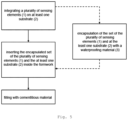
- Verfahren zur Herstellung einer Struktur aus zementhaltiges Material mit Sensoren von nach einem der vorhergehenden Ansprüche, wobei es die folgenden Schritte umfasst:a) Integrieren einer Vielzahl von Sensorelementen (1) auf dem mindestens einen Substrat (2) und anschließendes Abdecken des aus dem mindestens einen Substrat und der Vielzahl von Sensorelementen (1) gebildeten Satzes durch Einkapseln mit einer Abdichtungsmaterial Schicht (3) und Einschließen des gesamten Einheit, der durch die Abdichtungsmaterial Schicht (3), der Vielzahl von Sensorelementen (1) und dem mindestens einen Substrat (2) gebildet wird, mit einem zementhaltigen Material;b) Einlegen des gesamten Einheit in das zementhaltige Material einschließen innerhalb einer Schalung;c) Füllen der aus Schritt b) resultierenden Schalung mit zementhaltigem Material, wobei die genannten Sensorelemente so angeordnet sind, dass sie auf der Grundlage der Interaktion mit einem menschlichen Benutzer Variablen außerhalb der zementhaltigen Struktur erfassen können.
- Verfahren nach dem vorhergehenden Anspruch, dadurch gekennzeichnet, dass
Schritt a) besteht insbesondere darin, eine Vielzahl von Sensorelementen (1) auf mindestens ein Substrat (2) zu drucken, wobei das Drucken vorzugsweise aus einer der folgenden Techniken oder Kombinationen davon besteht:- Siebdruck;- Tiefdruck;- Tintenstrahldruck in Walzen- oder Bogensystemen. - Herstellungsverfahren nach einem der Ansprüche 10 und 11, dadurch gekennzeichnet, dass es für den Fall, dass das Substrat (2) aus einem nicht-zementhaltiges Substrat besteht, die folgenden Schritte umfasst:- Aufteilung der Betonierung in Außen- und Innenwandbetonierung;- Einführung der Vielzahl der auf mindestens ein Substrat (2) gedruckten Sensorelemente (1) nach deren Einkapseln in die Schalung während der Vorbereitung der Innenwandbetonierung;- in der Einführung des vorhergehenden Schritts, Positionierung der Vielzahl von Sensorelementen (1), die auf mindestens ein Substrat (2) gedruckt sind, mit Hilfe von Abstandshaltern aus zementhaltiges Material und ihre Befestigung an der Schalungsbewehrung mittels Federsystemen oder Ähnlichem;- allmähliches Einführung des zementhaltigen Materials, um die Sensorelemente und Zubehörteile nicht zu beschädigen;- Verwendung von Negativen in den Teilen, für die Platzierung und Montage von Verbindungsboxen an strategischen Punkten, die zuvor im Projekt festgelegt wurden;- Betonieren des gesamten Satzes mit Fertigbeton oder Beschichtungsbeton, je nach Dimensionierung und geplanter Art der Endbearbeitung.
- Herstellungsverfahren nach einem der Ansprüche 10 und 11, dadurch gekennzeichnet, dass in dem Fall, dass das Substrat (2) aus das zementhaltige Material selbst besteht, das Betonieren durch Schichten von vorgefertigten Strukturen für die endgültige Verwendung phasenweise erfolgt, was die folgenden Schritte umfasst:- Einbringen des Betons in einer ersten Schicht und Einlegen des Satzes aus der Vielzahl von Sensorelementen (1) und dem mindestens einem Substrat (2) unter diese Schicht;- Danach wird eine weitere Betonschicht eingebracht.
- Herstellungsverfahren nach einem der Ansprüche 10 und 11, dadurch gekennzeichnet, dass die Vielzahl von Sensorelementen (1) zuvor in ein vorgefertigtes Substrat (2) aus zementhaltiges Material - wie Mikrobeton, Mörtel oder kompatiblen Material - eingearbeitet wird, das außerdem die folgenden Schritte umfasst:- Vorformen des zementhaltigen Materials und Bedrucken der Vielzahl von Sensorelementen (1), wobei alle ihre Verbindungspunkte abgedeckt werden;- Einbringen der Struktur in die Konstruktion der Struktur aus zementhaltiges Material mit Sensoren, z. B. einer Wand, eines Bodens, eines dekorativen Teils oder einer Stadtmöblierung - vor dem Betonieren oder der endgültigen Beschichtung mit den zementhaltigen Materialien oder anderen;- Befestigung zwischen der Bewehrung und der Schalung mit Hilfe von Stützhaken und Abstandshaltern im Falle eines zu betonierenden Elements oder durch Verkleben auf der Unterlage zur Aufnahme der endgültigen Beschichtung im Falle der Anwendung unter einem Putz, Estrich oder einer anderen Beschichtung.
- Verfahren zum Betreiben der Struktur aus zementhaltiges Material mit Sensoren nach einem der Ansprüche 1 bis 9, wobei es die folgenden Schritte umfasst:- Erfassen eines Reizes außerhalb der Struktur aus zementhaltiges Material mit Sensoren durch die Vielzahl von Sensorelementen (1) und dadurch Erzeugen von Signalen;- Aufbereitung der von der Vielzahl der Sensorelemente (1) erzeugten Signale;- Verarbeitung der Signale von der Vielzahl von Sensorelementen (1) in mindestens einem Mikrocontroller (8) ;- Ansteuerung eines elektronischen Elements durch den mindestens einen Mikrocontroller (8), wobei das elektronische Element mindestens ein Betätigungselement (10) und/oder ein lokales oder entferntes Kommunikationsmittel (9) ist.
Applications Claiming Priority (1)
| Application Number | Priority Date | Filing Date | Title |
|---|---|---|---|
| PT108448A PT108448A (pt) | 2015-05-07 | 2015-05-07 | Estrutura de material cimentício sensorizada, seu método de produção e seu método de operação |
Publications (3)
| Publication Number | Publication Date |
|---|---|
| EP3100837A1 EP3100837A1 (de) | 2016-12-07 |
| EP3100837B1 true EP3100837B1 (de) | 2023-07-26 |
| EP3100837C0 EP3100837C0 (de) | 2023-07-26 |
Family
ID=56092701
Family Applications (1)
| Application Number | Title | Priority Date | Filing Date |
|---|---|---|---|
| EP16020173.7A Active EP3100837B1 (de) | 2015-05-07 | 2016-05-06 | Zementartige material struktur mit sensoren, deren herstellungsverfahren und deren betriebsverfahren |
Country Status (5)
| Country | Link |
|---|---|
| US (1) | US20160328929A1 (de) |
| EP (1) | EP3100837B1 (de) |
| BR (1) | BR102016010268A2 (de) |
| CA (1) | CA2929271A1 (de) |
| PT (1) | PT108448A (de) |
Families Citing this family (3)
| Publication number | Priority date | Publication date | Assignee | Title |
|---|---|---|---|---|
| WO2018005460A1 (en) * | 2016-06-27 | 2018-01-04 | Quipip, Llc | Sensing device, and systems and methods for obtaining data relating to concrete mixtures and concrete structures |
| US11815505B2 (en) * | 2017-09-29 | 2023-11-14 | Quipip, Llc | Sensor device, and systems and methods for obtaining and providing information relating to concrete mixtures and construction projects |
| CN113056603B (zh) * | 2018-09-28 | 2024-08-23 | 通用电气可再生能源西班牙有限公司 | 用于制造带有嵌入的增强感测元件的风力涡轮塔架结构的方法 |
Citations (1)
| Publication number | Priority date | Publication date | Assignee | Title |
|---|---|---|---|---|
| US20100026665A1 (en) * | 2006-10-27 | 2010-02-04 | Dupont Lightstone Aps | Building Block |
Family Cites Families (6)
| Publication number | Priority date | Publication date | Assignee | Title |
|---|---|---|---|---|
| US20060287140A1 (en) * | 2005-06-16 | 2006-12-21 | Brandt Richard A | Automated line calling system |
| US20070046479A1 (en) | 2005-08-26 | 2007-03-01 | Applied Sensor Research & Development Corporation | Concrete maturity monitoring system using passive wireless surface acoustic wave temperature sensors |
| CN102255959A (zh) | 2011-06-28 | 2011-11-23 | 淮阴师范学院 | 基于WSN及移动agent的混凝土施工信息监测系统 |
| TWI467306B (zh) * | 2012-01-19 | 2015-01-01 | E Ink Holdings Inc | 使用顯示器之球場邊線模組 |
| KR101336683B1 (ko) * | 2012-08-10 | 2013-12-09 | 주계원 | 라인 터치 감지 방법 및 시스템 |
| US8532815B1 (en) * | 2012-09-25 | 2013-09-10 | Romeo Ilarian Ciuperca | Method for electronic temperature controlled curing of concrete and accelerating concrete maturity or equivalent age of concrete structures and objects |
-
2015
- 2015-05-07 PT PT108448A patent/PT108448A/pt unknown
-
2016
- 2016-05-05 CA CA2929271A patent/CA2929271A1/en not_active Abandoned
- 2016-05-06 BR BR102016010268A patent/BR102016010268A2/pt not_active Application Discontinuation
- 2016-05-06 EP EP16020173.7A patent/EP3100837B1/de active Active
- 2016-05-08 US US15/149,133 patent/US20160328929A1/en not_active Abandoned
Patent Citations (1)
| Publication number | Priority date | Publication date | Assignee | Title |
|---|---|---|---|---|
| US20100026665A1 (en) * | 2006-10-27 | 2010-02-04 | Dupont Lightstone Aps | Building Block |
Also Published As
| Publication number | Publication date |
|---|---|
| BR102016010268A2 (pt) | 2016-11-08 |
| EP3100837C0 (de) | 2023-07-26 |
| PT108448A (pt) | 2016-11-07 |
| US20160328929A1 (en) | 2016-11-10 |
| EP3100837A1 (de) | 2016-12-07 |
| CA2929271A1 (en) | 2016-11-07 |
Similar Documents
| Publication | Publication Date | Title |
|---|---|---|
| EP3100837B1 (de) | Zementartige material struktur mit sensoren, deren herstellungsverfahren und deren betriebsverfahren | |
| CN107110700A (zh) | 具有混凝土制的传感器部段的电气器件、其制造方法及应用 | |
| EP2534929B1 (de) | Präsenzerkennungssystem und beleuchtungssystem mit einem solchen system | |
| KR20100101696A (ko) | 조명 타일링 시스템 | |
| SG160317A1 (en) | Actuating downhole devices in a wellbore | |
| US7315793B2 (en) | Apparatus, system and methods for collecting position information over a large surface using electrical field sensing devices | |
| US20080147350A1 (en) | Apparatus, system and methods for collecting position information over a large surface using electrical field sensing devices | |
| TW201116680A (en) | Wall or ceiling covering material | |
| EP3111729B1 (de) | Verfahren und vorrichtung zur steuerung der beleuchtungseinheiten basierend auf gemessener kraft und/oder bewegung von zugehörigen leuchten | |
| US10416331B2 (en) | Two-dimensional capacitive sensor for locating the presence of an object and/or of an individual | |
| KR20210116463A (ko) | 전기 노드, 전기 노드를 제조하기 위한 방법 및 전기 노드를 포함하는 다층 구조 | |
| WO2017213960A1 (en) | Glass substrates with touchscreen technology | |
| EP3070999A1 (de) | Steuerung von adressierbaren led-streifen | |
| CN106017568B (zh) | 预制装配式混凝土体系的结构健康监测系统及集成方法 | |
| DE202015007999U1 (de) | Plattenkörper | |
| CN109328327A (zh) | 用于非电子显示器基底表面的触摸敏感控制系统 | |
| WO2017099807A1 (en) | Subsurface electric field monitoring methods and systems employing a current focusing cement arrangement | |
| CN102395942A (zh) | 触摸传感器膜、包括其的触摸传感器组件和制造触摸传感器组件的方法 | |
| ES2955463T3 (es) | Estructura de material cementoso con sensores, procedimiento de fabricación y de funcionamiento de la misma | |
| DE102012107412B4 (de) | Aktivitätssensorik, Boden- oder Wandaufbauherstellungsverfahren sowie Aktivitätsauswerteverfahren | |
| CN212747878U (zh) | 一种集成传感器、房间设施及室内人居环境感知系统 | |
| ITCO20110018A1 (it) | Apparecchiatura per rilevare movimenti di terreno nel sottosuolo e disposizione che la utilizza | |
| TWI578186B (zh) | Identification system and identification device for identification with solar panels | |
| CN207277468U (zh) | 马桶器的检测电路 | |
| KR20210025248A (ko) | 사용자 반응형 스마트 보도 블럭 시스템 |
Legal Events
| Date | Code | Title | Description |
|---|---|---|---|
| PUAI | Public reference made under article 153(3) epc to a published international application that has entered the european phase |
Free format text: ORIGINAL CODE: 0009012 |
|
| STAA | Information on the status of an ep patent application or granted ep patent |
Free format text: STATUS: THE APPLICATION HAS BEEN PUBLISHED |
|
| AK | Designated contracting states |
Kind code of ref document: A1 Designated state(s): AL AT BE BG CH CY CZ DE DK EE ES FI FR GB GR HR HU IE IS IT LI LT LU LV MC MK MT NL NO PL PT RO RS SE SI SK SM TR |
|
| AX | Request for extension of the european patent |
Extension state: BA ME |
|
| STAA | Information on the status of an ep patent application or granted ep patent |
Free format text: STATUS: REQUEST FOR EXAMINATION WAS MADE |
|
| 17P | Request for examination filed |
Effective date: 20170306 |
|
| RBV | Designated contracting states (corrected) |
Designated state(s): AL AT BE BG CH CY CZ DE DK EE ES FI FR GB GR HR HU IE IS IT LI LT LU LV MC MK MT NL NO PL PT RO RS SE SI SK SM TR |
|
| STAA | Information on the status of an ep patent application or granted ep patent |
Free format text: STATUS: EXAMINATION IS IN PROGRESS |
|
| 17Q | First examination report despatched |
Effective date: 20210323 |
|
| GRAP | Despatch of communication of intention to grant a patent |
Free format text: ORIGINAL CODE: EPIDOSNIGR1 |
|
| STAA | Information on the status of an ep patent application or granted ep patent |
Free format text: STATUS: GRANT OF PATENT IS INTENDED |
|
| INTG | Intention to grant announced |
Effective date: 20230214 |
|
| GRAS | Grant fee paid |
Free format text: ORIGINAL CODE: EPIDOSNIGR3 |
|
| GRAA | (expected) grant |
Free format text: ORIGINAL CODE: 0009210 |
|
| STAA | Information on the status of an ep patent application or granted ep patent |
Free format text: STATUS: THE PATENT HAS BEEN GRANTED |
|
| AK | Designated contracting states |
Kind code of ref document: B1 Designated state(s): AL AT BE BG CH CY CZ DE DK EE ES FI FR GB GR HR HU IE IS IT LI LT LU LV MC MK MT NL NO PL PT RO RS SE SI SK SM TR |
|
| REG | Reference to a national code |
Ref country code: GB Ref legal event code: FG4D |
|
| REG | Reference to a national code |
Ref country code: CH Ref legal event code: EP |
|
| REG | Reference to a national code |
Ref country code: IE Ref legal event code: FG4D |
|
| REG | Reference to a national code |
Ref country code: DE Ref legal event code: R096 Ref document number: 602016081289 Country of ref document: DE |
|
| U01 | Request for unitary effect filed |
Effective date: 20230824 |
|
| U07 | Unitary effect registered |
Designated state(s): AT BE BG DE DK EE FI FR IT LT LU LV MT NL PT SE SI Effective date: 20230830 |
|
| RAP4 | Party data changed (patent owner data changed or rights of a patent transferred) |
Owner name: CENTI - CENTRO DE NANOTECNOLOGIA E MATERIAIS TECNICOS FUNCIONAIS E INTELIGENTES Owner name: SECIL-COMPANHIA GERAL DE CAL E CIMENTO S.A. |
|
| U1H | Name or address of the proprietor changed after the registration of the unitary effect |
Owner name: CENTI - CENTRO DE NANOTECNOLOGIA E MATERIAIS TECNICOS FUNCIONAIS E INTELIGENTES; PT Owner name: SECIL-COMPANHIA GERAL DE CAL E CIMENTO S.A.; PT |
|
| REG | Reference to a national code |
Ref country code: LT Ref legal event code: MG9D |
|
| REG | Reference to a national code |
Ref country code: ES Ref legal event code: FG2A Ref document number: 2955463 Country of ref document: ES Kind code of ref document: T3 Effective date: 20231201 |
|
| PG25 | Lapsed in a contracting state [announced via postgrant information from national office to epo] |
Ref country code: IS Free format text: LAPSE BECAUSE OF FAILURE TO SUBMIT A TRANSLATION OF THE DESCRIPTION OR TO PAY THE FEE WITHIN THE PRESCRIBED TIME-LIMIT Effective date: 20231126 |
|
| PG25 | Lapsed in a contracting state [announced via postgrant information from national office to epo] |
Ref country code: RS Free format text: LAPSE BECAUSE OF FAILURE TO SUBMIT A TRANSLATION OF THE DESCRIPTION OR TO PAY THE FEE WITHIN THE PRESCRIBED TIME-LIMIT Effective date: 20230726 Ref country code: NO Free format text: LAPSE BECAUSE OF FAILURE TO SUBMIT A TRANSLATION OF THE DESCRIPTION OR TO PAY THE FEE WITHIN THE PRESCRIBED TIME-LIMIT Effective date: 20231026 Ref country code: IS Free format text: LAPSE BECAUSE OF FAILURE TO SUBMIT A TRANSLATION OF THE DESCRIPTION OR TO PAY THE FEE WITHIN THE PRESCRIBED TIME-LIMIT Effective date: 20231126 Ref country code: HR Free format text: LAPSE BECAUSE OF FAILURE TO SUBMIT A TRANSLATION OF THE DESCRIPTION OR TO PAY THE FEE WITHIN THE PRESCRIBED TIME-LIMIT Effective date: 20230726 |
|
| PG25 | Lapsed in a contracting state [announced via postgrant information from national office to epo] |
Ref country code: PL Free format text: LAPSE BECAUSE OF FAILURE TO SUBMIT A TRANSLATION OF THE DESCRIPTION OR TO PAY THE FEE WITHIN THE PRESCRIBED TIME-LIMIT Effective date: 20230726 |
|
| REG | Reference to a national code |
Ref country code: DE Ref legal event code: R097 Ref document number: 602016081289 Country of ref document: DE |
|
| PG25 | Lapsed in a contracting state [announced via postgrant information from national office to epo] |
Ref country code: SM Free format text: LAPSE BECAUSE OF FAILURE TO SUBMIT A TRANSLATION OF THE DESCRIPTION OR TO PAY THE FEE WITHIN THE PRESCRIBED TIME-LIMIT Effective date: 20230726 Ref country code: RO Free format text: LAPSE BECAUSE OF FAILURE TO SUBMIT A TRANSLATION OF THE DESCRIPTION OR TO PAY THE FEE WITHIN THE PRESCRIBED TIME-LIMIT Effective date: 20230726 Ref country code: CZ Free format text: LAPSE BECAUSE OF FAILURE TO SUBMIT A TRANSLATION OF THE DESCRIPTION OR TO PAY THE FEE WITHIN THE PRESCRIBED TIME-LIMIT Effective date: 20230726 Ref country code: SK Free format text: LAPSE BECAUSE OF FAILURE TO SUBMIT A TRANSLATION OF THE DESCRIPTION OR TO PAY THE FEE WITHIN THE PRESCRIBED TIME-LIMIT Effective date: 20230726 |
|
| U20 | Renewal fee for the european patent with unitary effect paid |
Year of fee payment: 9 Effective date: 20240412 |
|
| PLBE | No opposition filed within time limit |
Free format text: ORIGINAL CODE: 0009261 |
|
| STAA | Information on the status of an ep patent application or granted ep patent |
Free format text: STATUS: NO OPPOSITION FILED WITHIN TIME LIMIT |
|
| 26N | No opposition filed |
Effective date: 20240429 |
|
| REG | Reference to a national code |
Ref country code: CH Ref legal event code: PL |
|
| PG25 | Lapsed in a contracting state [announced via postgrant information from national office to epo] |
Ref country code: MC Free format text: LAPSE BECAUSE OF FAILURE TO SUBMIT A TRANSLATION OF THE DESCRIPTION OR TO PAY THE FEE WITHIN THE PRESCRIBED TIME-LIMIT Effective date: 20230726 |
|
| PG25 | Lapsed in a contracting state [announced via postgrant information from national office to epo] |
Ref country code: MC Free format text: LAPSE BECAUSE OF FAILURE TO SUBMIT A TRANSLATION OF THE DESCRIPTION OR TO PAY THE FEE WITHIN THE PRESCRIBED TIME-LIMIT Effective date: 20230726 Ref country code: CH Free format text: LAPSE BECAUSE OF NON-PAYMENT OF DUE FEES Effective date: 20240531 |
|
| U20 | Renewal fee for the european patent with unitary effect paid |
Year of fee payment: 10 Effective date: 20250310 |
|
| PG25 | Lapsed in a contracting state [announced via postgrant information from national office to epo] |
Ref country code: IE Free format text: LAPSE BECAUSE OF NON-PAYMENT OF DUE FEES Effective date: 20240506 |
|
| PGFP | Annual fee paid to national office [announced via postgrant information from national office to epo] |
Ref country code: ES Payment date: 20250603 Year of fee payment: 10 |
|
| PG25 | Lapsed in a contracting state [announced via postgrant information from national office to epo] |
Ref country code: CY Free format text: LAPSE BECAUSE OF FAILURE TO SUBMIT A TRANSLATION OF THE DESCRIPTION OR TO PAY THE FEE WITHIN THE PRESCRIBED TIME-LIMIT; INVALID AB INITIO Effective date: 20160506 |
|
| PG25 | Lapsed in a contracting state [announced via postgrant information from national office to epo] |
Ref country code: HU Free format text: LAPSE BECAUSE OF FAILURE TO SUBMIT A TRANSLATION OF THE DESCRIPTION OR TO PAY THE FEE WITHIN THE PRESCRIBED TIME-LIMIT; INVALID AB INITIO Effective date: 20160506 |
|
| PG25 | Lapsed in a contracting state [announced via postgrant information from national office to epo] |
Ref country code: GR Free format text: LAPSE BECAUSE OF FAILURE TO SUBMIT A TRANSLATION OF THE DESCRIPTION OR TO PAY THE FEE WITHIN THE PRESCRIBED TIME-LIMIT; INVALID AB INITIO Effective date: 20160506 |
|
| U20 | Renewal fee for the european patent with unitary effect paid |
Year of fee payment: 11 Effective date: 20260302 |
|
| PGFP | Annual fee paid to national office [announced via postgrant information from national office to epo] |
Ref country code: GB Payment date: 20260313 Year of fee payment: 11 |