EP3100796A1 - Press-forming method and method of manufacturing press-formed product - Google Patents
Press-forming method and method of manufacturing press-formed product Download PDFInfo
- Publication number
- EP3100796A1 EP3100796A1 EP15742980.4A EP15742980A EP3100796A1 EP 3100796 A1 EP3100796 A1 EP 3100796A1 EP 15742980 A EP15742980 A EP 15742980A EP 3100796 A1 EP3100796 A1 EP 3100796A1
- Authority
- EP
- European Patent Office
- Prior art keywords
- press
- blank material
- press forming
- bent
- hat
- Prior art date
- Legal status (The legal status is an assumption and is not a legal conclusion. Google has not performed a legal analysis and makes no representation as to the accuracy of the status listed.)
- Granted
Links
Images






Classifications
-
- B—PERFORMING OPERATIONS; TRANSPORTING
- B21—MECHANICAL METAL-WORKING WITHOUT ESSENTIALLY REMOVING MATERIAL; PUNCHING METAL
- B21D—WORKING OR PROCESSING OF SHEET METAL OR METAL TUBES, RODS OR PROFILES WITHOUT ESSENTIALLY REMOVING MATERIAL; PUNCHING METAL
- B21D22/00—Shaping without cutting, by stamping, spinning, or deep-drawing
- B21D22/20—Deep-drawing
- B21D22/203—Deep-drawing of compound articles
-
- B—PERFORMING OPERATIONS; TRANSPORTING
- B21—MECHANICAL METAL-WORKING WITHOUT ESSENTIALLY REMOVING MATERIAL; PUNCHING METAL
- B21D—WORKING OR PROCESSING OF SHEET METAL OR METAL TUBES, RODS OR PROFILES WITHOUT ESSENTIALLY REMOVING MATERIAL; PUNCHING METAL
- B21D22/00—Shaping without cutting, by stamping, spinning, or deep-drawing
- B21D22/20—Deep-drawing
- B21D22/26—Deep-drawing for making peculiarly, e.g. irregularly, shaped articles
-
- B—PERFORMING OPERATIONS; TRANSPORTING
- B21—MECHANICAL METAL-WORKING WITHOUT ESSENTIALLY REMOVING MATERIAL; PUNCHING METAL
- B21D—WORKING OR PROCESSING OF SHEET METAL OR METAL TUBES, RODS OR PROFILES WITHOUT ESSENTIALLY REMOVING MATERIAL; PUNCHING METAL
- B21D11/00—Bending not restricted to forms of material mentioned in only one of groups B21D5/00, B21D7/00, B21D9/00; Bending not provided for in groups B21D5/00 - B21D9/00; Twisting
- B21D11/08—Bending by altering the thickness of part of the cross-section of the work
-
- B—PERFORMING OPERATIONS; TRANSPORTING
- B21—MECHANICAL METAL-WORKING WITHOUT ESSENTIALLY REMOVING MATERIAL; PUNCHING METAL
- B21D—WORKING OR PROCESSING OF SHEET METAL OR METAL TUBES, RODS OR PROFILES WITHOUT ESSENTIALLY REMOVING MATERIAL; PUNCHING METAL
- B21D22/00—Shaping without cutting, by stamping, spinning, or deep-drawing
- B21D22/20—Deep-drawing
- B21D22/206—Deep-drawing articles from a strip in several steps, the articles being coherent with the strip during the operation
-
- B—PERFORMING OPERATIONS; TRANSPORTING
- B21—MECHANICAL METAL-WORKING WITHOUT ESSENTIALLY REMOVING MATERIAL; PUNCHING METAL
- B21D—WORKING OR PROCESSING OF SHEET METAL OR METAL TUBES, RODS OR PROFILES WITHOUT ESSENTIALLY REMOVING MATERIAL; PUNCHING METAL
- B21D35/00—Combined processes according to or processes combined with methods covered by groups B21D1/00 - B21D31/00
- B21D35/001—Shaping combined with punching, e.g. stamping and perforating
-
- B—PERFORMING OPERATIONS; TRANSPORTING
- B21—MECHANICAL METAL-WORKING WITHOUT ESSENTIALLY REMOVING MATERIAL; PUNCHING METAL
- B21D—WORKING OR PROCESSING OF SHEET METAL OR METAL TUBES, RODS OR PROFILES WITHOUT ESSENTIALLY REMOVING MATERIAL; PUNCHING METAL
- B21D5/00—Bending sheet metal along straight lines, e.g. to form simple curves
- B21D5/01—Bending sheet metal along straight lines, e.g. to form simple curves between rams and anvils or abutments
-
- B—PERFORMING OPERATIONS; TRANSPORTING
- B21—MECHANICAL METAL-WORKING WITHOUT ESSENTIALLY REMOVING MATERIAL; PUNCHING METAL
- B21D—WORKING OR PROCESSING OF SHEET METAL OR METAL TUBES, RODS OR PROFILES WITHOUT ESSENTIALLY REMOVING MATERIAL; PUNCHING METAL
- B21D53/00—Making other particular articles
- B21D53/88—Making other particular articles other parts for vehicles, e.g. cowlings, mudguards
-
- B—PERFORMING OPERATIONS; TRANSPORTING
- B21—MECHANICAL METAL-WORKING WITHOUT ESSENTIALLY REMOVING MATERIAL; PUNCHING METAL
- B21D—WORKING OR PROCESSING OF SHEET METAL OR METAL TUBES, RODS OR PROFILES WITHOUT ESSENTIALLY REMOVING MATERIAL; PUNCHING METAL
- B21D7/00—Bending rods, profiles, or tubes
- B21D7/06—Bending rods, profiles, or tubes in press brakes or between rams and anvils or abutments; Pliers with forming dies
Definitions
- the present invention relates to a technology for manufacturing, by press forming, a formed product having a U-shaped cross section having at least a top plate portion and side wall portions continuous with both sides thereof in a width direction, and having a bent portion bent in a plate thickness direction of the top plate portion.
- Patent Literatures 1 and 2 have been heretofore present as measures against a springback deformation (for example, a camber back) that occurs in a formed product (for example, a U-shaped member or a hat-shaped member) having a U-shaped cross section having at least a top plate portion and side wall portions continuous with both sides thereof in a width direction, and having a bent portion bent in a plate thickness direction of the top plate portion.
- a springback deformation for example, a camber back
- a formed product for example, a U-shaped member or a hat-shaped member
- the camber back is a phenomenon that, in a case of forming the above-mentioned formed product having the bent portion, the formed product, which is bent, returns slightly to an original shape thereof after being released.
- Patent Literature 1 discloses a method, in which a difference between a curvature radius of a top plate portion of a hat-shaped member and a curvature radius of a flange portion of the hat-shaped member is made larger than a height of the side wall portion, whereby the residual stress of the formed product owing to the press forming is reduced, and the camber back that occurs in the formed product is suppressed.
- Patent Literature 2 discloses a method, in which the bent portion of the formed product is deformed with pressure in an anti-swelling direction in the course of the press forming of the formed product, whereby the residual stress of the formed product owing to the press forming is reduced, and the camber back that occurs in the formed product is suppressed.
- Patent Literatures 1 and 2 it is necessary to restrict a shape of the formed product though the camber back that occurs in the formed product can be suppressed, and there has been a problem of lack of versatility.
- the present invention has been made focusing on the point as described above, and it is an object of the present invention to provide a press forming technology capable of reducing the camber back, which occurs in the press formed product, while reducing the restriction on the shape of the press formed product.
- a press forming method is a press forming method of press forming a formed product having a U-shaped cross section having at least a top plate portion and side wall portions continuous with both sides of the top plate portion in a width direction, and having a bent portion bent in a plate thickness direction of the top plate portion.
- the above press forming method includes at a time of press forming the formed product, fixing a blank material between a pair of press dies, which have bent surfaces for press forming the bent portion of the formed product, while warping the blank material in a bending direction of the bent surfaces of the pair of press dies, the blank material having at least a longer longitudinal line length than a longitudinal line length of the top plate portion of the formed product, and press forming the bent portion on the fixed blank material by using the bent surfaces of the pair of press dies.
- a method for manufacturing a press formed product is a method of press forming a formed product having a U-shaped cross section having at least a top plate portion and side wall portions continuous with both sides of the top plate portion in a width direction, and having a bent portion bent in a plate thickness direction of the top plate portion.
- the above method includes fixing a blank material between a pair of press dies, which have bent surfaces for press forming the bent portion of the formed product, while warping the blank material in a bending direction of the bent surfaces of the pair of press dies, the blank material having at least a longer longitudinal line length than a longitudinal line length of the top plate portion of the formed product, and press forming the bent portion on the fixed blank material by using the bent surfaces of the pair of press dies.
- a gap is formed between a head portion of the press die and the blank material. Therefore, in accordance with the aspect of the present invention, during the press forming, the gap between the head portion of the press die and the blank material is crushed in an opposite direction to the bending direction of the blank material, and a compressive stress is generated in the longitudinal direction of the blank material. As a result, in accordance with the aspect of the present invention, a residual tensile stress on an outer bent side of the formed product can be reduced, and a residual bending moment of the formed product can be reduced. Therefore, in accordance with the aspect of the present invention, the occurrence of the camber back in the formed product can be suppressed. In such a way, in accordance with the aspect of the present invention, the camber back that occurs in the formed product can be reduced while reducing the restriction on the shape of the formed product.
- a blank material 4 is manufactured into a press formed product (hereinafter, also referred to as a "hat-shaped member") 5, which has a hat-shaped cross section and has a bent portion bent to be convex in a direction of a top plate portion 5a, by press forming by using a press forming device 1 (lower die 2, upper die 3), the top plate portion 5a becomes a portion on an outer bent side (convex side), and accordingly, a longitudinal tensile stress is generated in the top plate portion 5a.
- the blank material 4 is a plate-like raw material cut for the press forming.
- the hat-shaped cross section includes one in which flange portions 5c are further added to a U-shaped cross section having at least the top plate portion 5a and side wall portions 5b continuous with both sides of the top plate portion 5a in a width direction (refer to FIG. 2B ). That is to say, the hat-shaped cross section has a cross-sectional shape including at least the U-shaped cross section. Moreover, the flange portions 5c become portions on an inner bent side, and accordingly, a longitudinal compressive stress is generated in the flange portions 5c.
- FIG. 2A illustrates the hat-shaped member 5 viewed from the side wall portion 5b side
- FIG. 2B illustrates an end surface viewed by cutting the hat-shaped member 5 on a cross section taken along a line A-A of FIG. 2A
- FIG. 3 illustrates an FEM (Finite Element Method) analysis result of the hat-shaped member 5 viewed from the top plate portion 5a side.
- approximately 500 MPa tensile stress
- approximately -1200 MPa compressive stress
- the camber back refers to a phenomenon that a material, which is bent, returns to an original shape thereof.
- the inventor of the present invention thinks that this camber back can be suppressed by reducing the tensile stress generated in the top plate portion 5a and reducing the bending moment M, and for this suppression, thinks of a press forming method and a method for manufacturing a press formed product, each of which applies a compressive stress, which is reverse to the tensile stress, to the top plate portion 5a.
- the press forming device 1 of this embodiment includes the lower die and the upper die 3 disposed oppositely to the lower die 2.
- a bent surface hereinafter, also referred to as a "convex surface" 2a for press forming the bent portion bent upward.
- a shape for press forming the hat-shaped cross section in which the top plate portion 5a is formed in an upper portion (in a bending direction), and an opening portion is formed in a lower portion therein.
- a bent surface 3a (hereinafter, also referred to as a "concave surface 3a") corresponding to a shape of the convex surface 2a.
- the upper die 3 approaches the lower die 2 by lifting means (not illustrated), presses the blank material 4, which is interposed between the lower die 2 and the upper die 3, and is thereby capable of press forming the press formed product.
- the hat-shaped member 5 which has the hat-shaped cross section and has the bent portion bent in the plate thickness direction of the top plate portion 5a, is press formed (formed).
- the press forming device 1 of this embodiment further includes a pair of wall portions 6, which are opposed to individual outer peripheries on both longitudinal ends of the lower die 2.
- the pair of wall portions 6 are provided apart from each other by a distance equal to a distance between both longitudinal ends of the hat-shaped member 5 which is already formed. Then, before performing the press forming for the blank material 4 by pressing the same by the upper die 3 and the lower die 2, both longitudinal ends of the blank material 4 are individually allowed to abut against the pair of wall portions 6, whereby the pair of wall portions 6 are made capable of fixing (restraining) both longitudinal ends of the blank material 4, that is, capable of suppressing a longitudinal displacement of the blank material 4.
- the blank material 4 is interposed between the lower die 2 and the upper die 3.
- the blank material 4 one is adopted, in which at least a longitudinal length (line length) is longer than a longitudinal length (line length) of the top plate portion 5a of the hat-shaped member 5, that is, in which the longitudinal length (line length) is longer than a longitudinal length (line length) of the convex surface 2a and the concave surface 3a.
- a longitudinal length (line length) is longer than a longitudinal length (line length) of the convex surface 2a and the concave surface 3a.
- the longitudinal length (line length) L of the blank material 4 is set so as to satisfy Lo ⁇ L ⁇ 1.020 ⁇ Lo. That is to say, preferably, a difference between the longitudinal length (line length) L of the blank material 4 and the longitudinal length (line length) Lo of the hat-shaped member 5 is set to 2% or less.
- both longitudinal ends of the blank material 4 are individually allowed to abut against the pair of individual wall portions 6, and individual lower surfaces of both longitudinal ends of the blank material 4 are brought into contact with the upper surface of the lower die 2.
- both longitudinal ends of the blank material 4 are spaced apart from each other by the distance equal to that between both longitudinal ends of the hat-shaped member 5, and in addition, both longitudinal ends of the blank material 4 are fixed (restrained). At this time, a gap is formed between a head portion of the convex surface 2a of the lower die 2 and the blank material 4.
- a configuration capable of positionally adjusting the pair of wall portions 6 in an opposite direction, a configuration may be adopted so that, after being once retreated right and left, the pair of wall portions 6 are allowed to approach each other one more time and to be set to a state of FIG. 5B . In this case, it is made possible to finely adjust the distance between the pair of wall portions 6 in matching with the line length of the blank material 4.
- the upper die 3 is lowered by the lifting means, and the bent portion is press formed on the fixed blank material 4 by using the convex surface 2a of the lower die 2 and the concave surface 3a of the upper die 3.
- the blank material 4 is subjected to the press forming (forming) into the hat-shaped member 5, which has the hat-shaped cross section and has the bent portion bent upward (in the plate thickness direction of the top plate portion 5a in the hat-shaped cross section).
- FIG. 7 illustrates an FEM analysis result of the hat-shaped member 5 viewed from the top plate portion 5a side.
- approximately -250 MPa compress stress
- approximately -1200 MPa compress stress
- the shape of the hat-shaped member 5 is not limited.
- the lower die 2 and the upper die 3 in FIG. 4 and FIGS. 5A to 5C compose a press die.
- the press die refers to a "press metal die”.
- the press forming method according to the first embodiment exerts the following effects.
- the longitudinal line length of the blank material 4 can be restricted. Therefore, the reduction of the buckling load of the blank material 4 can be suppressed, and during the press forming, the buckling of the blank material 4 owing to the compressive stress generated in the longitudinal direction of the blank material 4 can be prevented.
- a press forming method In a press forming method according to the second embodiment, following steps are executed. That is a first forming step of press forming the hat-shaped cross section on the blank material 4, and a second forming step of press forming the bent portion on the blank material 4 on which the hat-shaped cross section is press formed in the first step.
- a first press forming device 7 is used in the first forming step.
- a second press forming device 8 is used.
- the first press forming device 7 includes a lower die and an upper die 10 provided above the lower die 9 so as to be capable of ascending/descending.
- a shape hereinafter, also referred to as a "convex surface” 9a for press forming the hat-shaped cross section, in which the top plate portion 5a is formed in an upper portion, and an opening portion is formed in a lower portion, on the blank material 4.
- a shape hereinafter, also referred to as a "concave surface” 10a corresponding to the shape of the convex surface 9a.
- the upper die 10 is lowered by the lifting means (not illustrated), and presses the blank material 4 interposed between the lower die 9 and the upper die 10. In such a way, the hat-shaped cross section is press formed (formed).
- the second press forming device 8 includes a lower die 11 and an upper die 12 provided above the lower die 11 so as to be capable of ascending/descending. Between the lower die 11 and the upper die 12, the blank material 4 on which the hat-shaped cross section is press formed is interposed while directing the top plate portion 5a upward and directing the opening portion downward.
- a bent surface (hereinafter, also referred to as a "convex surface”) 11a for press forming a bent portion formed by bending the blank material 4, on which the hat-shaped cross section is formed by the first press forming device 7, upward (in the direction of the top plate portion 5a in the hat-shaped cross section).
- a bent surface hereinafter, also referred to as a "concave surface” 12b corresponding to the convex surface 2a.
- the upper die 12 is lowered by the lifting means (not illustrated), and presses the blank material 4 interposed between the lower die 9 and the upper die 12.
- the hat-shaped member 5 which has the hat-shaped cross section and has the bent portion bent in the plate thickness direction of the top plate portion 5a, is press formed (formed).
- the second press forming device 8 further includes a pair of wall portions 13, which are opposed to individual outer peripheries on both longitudinal ends of the lower die 11.
- the pair of wall portions 13 are provided apart from each other by a distance equal to the distance between both longitudinal ends of the hat-shaped member 5. Then, both longitudinal ends of the blank material 4, on which the hat-shaped cross section is formed by the first press forming device 7, individually abut against the pair of wall portions 13, whereby the pair of wall portions 13 fix (restrain) both longitudinal ends of the blank material 4, that is, suppress a longitudinal displacement of the blank material 4.
- the blank material 4 is mounted on the upper surface of the lower die 9 of the first press forming device 7.
- the blank material 4 there is adopted at least one in which a longitudinal length (line length) is longer than the longitudinal length (line length) of the top plate portion 5a of the hat-shaped member 5.
- the blank material 4 there is adopted one that satisfies the condition of Lo ⁇ L ⁇ 1.02 ⁇ Lo in the case where L is the longitudinal length (line length) of the blank material 4, and Lo is the longitudinal length (line length) of the hat-shaped member 5.
- the upper die 10 is lowered to the blank material 4 by the lifting means, and the hat-shaped cross section is press formed (formed) on the mounted blank material 4 by using the convex surface 9a of the lower die 9 and the concave surface 10a of the upper die 10. At the time of this press forming, both longitudinal end portions of the blank material 4 are not fixed.
- the second press forming device 8 there is executed the second forming step of press forming the bent portion on the blank material 4 on which the hat-shaped cross section is press formed in the first step.
- the blank material 4 on which the hat-shaped cross section is press formed in the first step is interposed between the lower die 11 and upper die 12 of the second press forming device 8.
- the blank material 4 on which the hat-shaped cross section is press formed in the first step is interposed while directing the top plate portion 5a upward and directing the opening portion downward.
- FIG. 12A the blank material 4 on which the hat-shaped cross section is press formed in the first step is interposed between the lower die 11 and upper die 12 of the second press forming device 8.
- the blank material 4 on which the hat-shaped cross section is press formed in the first step is interposed while directing the top plate portion 5a upward and directing the opening portion downward.
- both longitudinal ends of the blank material 4 are individually allowed to abut against the pair of individual wall portions 13, and individual lower surfaces of both longitudinal ends of the blank material 4 are brought into contact with the upper surface of the lower die 11.
- both longitudinal ends of the blank material 4 are spaced apart from each other by the distance equal to that between both longitudinal ends of the hat-shaped member 5, and in addition, both longitudinal ends of the blank material 4 are fixed (restrained).
- a gap is formed between a head portion of the convex surface 11a of the lower die 11 and the blank material 4.
- the upper die 12 is lowered by the lifting means, and the bent portion is press formed on the fixed blank material 4 by using the convex surface 11a of the lower die 11 and the concave surface 12a of the upper die 12.
- the blank material 4 is subjected to the press forming into the hat-shaped member 5, which has the hat-shaped cross section and has the bent portion bent upward (in the plate thickness direction of the top plate portion 5a in the hat-shaped cross section).
- the gap between the head portion of the convex surface 11a of the lower die 11 and the blank material 4 is crushed downward, that is, in an opposite direction to the bending direction of the blank material 4. Then, when the gap is crushed, then a longitudinal compressive stress is generated in the blank material 4. Therefore, when the hat-shaped member 5 is released from the lower die 11 and the upper die 12 after the press forming, the bending moment M generated in the hat-shaped member 5 can be reduced. In such a way, an occurrence amount of the camber back in the hat-shaped member 5 can be suppressed.
- the lower die 11 and the upper die 12 in FIG. 10 and FIGS. 12A to 12D compose a press die.
- the press die refers to a "press metal die”.
- the press forming method according to the second embodiment exerts the following effects in addition to the effects described in the first embodiment.
- the forming of the cross-sectional shape and the bending of the blank material 4 can be realized by different press dies. Therefore, the press dies can be formed simpler in terms of shape.
- the upper die 3 is divided into portions (hereinafter, also referred to as "non-bent-portion dies") 3b for press forming the non-bent portions of the hat-shaped member 5, and a portion (hereinafter, also referred to as a "bent-portion die”) 3c for press forming the bent portion.
- the press forming of the non-bent portions is first performed by using the non-bent-portion dies 3b as illustrated in FIG. 16A , and thereafter, the press forming of the curved portion is performed by using the bent-portion die 3c as illustrated in FIG. 16B .
- the blank material 4 on which the non-bent portions are press formed can be fixed while being warped in the bending direction of the bent surfaces of the lower die 2 and the bent-portion die 3c, and the bent portion can be press formed on the fixed blank material 4 by using the lower die 2 and the bent-portion die 3c. Therefore, the camber back that occurs at the time of press forming the bent portion can be reduced effectively while making it possible to press forming the non-bent portions partially in the longitudinal direction.
- the press forming method according to the first embodiment was used, and the camber back amount of the hat-shaped member 5 and presence of the buckling thereof in a case of press forming a hat-shaped member 5 having a simple hat-shaped cross section illustrated in FIG. 17A were evaluated.
- the FEM analysis was used for the evaluation of the camber back amount and the presence of the buckling.
- LS-DYNA version 971 was used as a solver, and an arithmetic operation was performed by using a dynamic explicit method.
- a mesh size was set to 2 mm, and a friction coefficient was set to 0.12.
- As a material an 1180 MPa-class cold-rolled steel sheet with a thickness of 1.2 mm was used.
- a true stress-true strain relationship approximated by the Expression of Swift based on a true stress-true strain curve obtained from JIS No. 5 Tensile Test was used.
- the camber back amounts thereof ranged from 11. 4 [mm] to 3.6 [mm].
- the press forming method according to the first embodiment it was able to be confirmed that the camber back amount that occurs in the hat-shaped member 5 can be reduced in comparison with the press forming method of Comparative example.
- the press forming method according to the first embodiment it was able to be confirmed that the buckling occurs on both longitudinal ends of the hat-shaped member 5 when the ratio L/Lo of the longitudinal length (line length) L of the blank material 4 to the longitudinal length (line length) Lo of the hat-shaped member 5 becomes larger than 1.020.
- the press forming method according to the first embodiment was used, and the camber back amount of the hat-shaped member 5 and the presence of the buckling thereof in a case of press forming the hat-shaped member 5 having such a hat-shaped cross section in which a top plate portion 5a illustrated in FIG. 17 is partially given a shape, were evaluated.
Landscapes
- Engineering & Computer Science (AREA)
- Mechanical Engineering (AREA)
- Shaping Metal By Deep-Drawing, Or The Like (AREA)
- Bending Of Plates, Rods, And Pipes (AREA)
Abstract
Description
- The present invention relates to a technology for manufacturing, by press forming, a formed product having a U-shaped cross section having at least a top plate portion and side wall portions continuous with both sides thereof in a width direction, and having a bent portion bent in a plate thickness direction of the top plate portion.
- In recent years, as a structural member of an automobile, a thin high-tensile steel plate or a thin aluminum alloy plate has been more often used in order to reduce weight of a vehicle body. When a formed product is released from press dies after the high-tensile steel plate or the aluminum alloy plate, which is as described above, is subjected to press forming, then a residual stress generated in the formed product is released. Thereby a springback deformation occurs, which causes a deterioration of dimensional accuracy of the formed product. Therefore, some press forming methods in which the springback deformation is hard to occur have been proposed.
- Among them, methods disclosed in
Patent Literatures -
Patent Literature 1 discloses a method, in which a difference between a curvature radius of a top plate portion of a hat-shaped member and a curvature radius of a flange portion of the hat-shaped member is made larger than a height of the side wall portion, whereby the residual stress of the formed product owing to the press forming is reduced, and the camber back that occurs in the formed product is suppressed. - Moreover,
Patent Literature 2 discloses a method, in which the bent portion of the formed product is deformed with pressure in an anti-swelling direction in the course of the press forming of the formed product, whereby the residual stress of the formed product owing to the press forming is reduced, and the camber back that occurs in the formed product is suppressed. -
- PTL 1:
JP 2013-063462 A - PTL 2:
JP 2010-207906 A - However, in the technologies described in
Patent Literatures - The present invention has been made focusing on the point as described above, and it is an object of the present invention to provide a press forming technology capable of reducing the camber back, which occurs in the press formed product, while reducing the restriction on the shape of the press formed product.
- In order to solve the above-described problem, a press forming method according to an aspect of the present invention is a press forming method of press forming a formed product having a U-shaped cross section having at least a top plate portion and side wall portions continuous with both sides of the top plate portion in a width direction, and having a bent portion bent in a plate thickness direction of the top plate portion. The above press forming method includes at a time of press forming the formed product, fixing a blank material between a pair of press dies, which have bent surfaces for press forming the bent portion of the formed product, while warping the blank material in a bending direction of the bent surfaces of the pair of press dies, the blank material having at least a longer longitudinal line length than a longitudinal line length of the top plate portion of the formed product, and press forming the bent portion on the fixed blank material by using the bent surfaces of the pair of press dies.
- Moreover, a method for manufacturing a press formed product according to an aspect of the present invention is a method of press forming a formed product having a U-shaped cross section having at least a top plate portion and side wall portions continuous with both sides of the top plate portion in a width direction, and having a bent portion bent in a plate thickness direction of the top plate portion. The above method includes fixing a blank material between a pair of press dies, which have bent surfaces for press forming the bent portion of the formed product, while warping the blank material in a bending direction of the bent surfaces of the pair of press dies, the blank material having at least a longer longitudinal line length than a longitudinal line length of the top plate portion of the formed product, and press forming the bent portion on the fixed blank material by using the bent surfaces of the pair of press dies.
- In accordance with the aspect of the present invention, a gap is formed between a head portion of the press die and the blank material. Therefore, in accordance with the aspect of the present invention, during the press forming, the gap between the head portion of the press die and the blank material is crushed in an opposite direction to the bending direction of the blank material, and a compressive stress is generated in the longitudinal direction of the blank material. As a result, in accordance with the aspect of the present invention, a residual tensile stress on an outer bent side of the formed product can be reduced, and a residual bending moment of the formed product can be reduced. Therefore, in accordance with the aspect of the present invention, the occurrence of the camber back in the formed product can be suppressed. In such a way, in accordance with the aspect of the present invention, the camber back that occurs in the formed product can be reduced while reducing the restriction on the shape of the formed product.
-
-
FIG. 1 is a cross-sectional view illustrating a schematic configuration of a press forming device; -
FIGS. 2A and 2B are views illustrating a configuration of a hat-shaped member; -
FIG. 3 is a view illustrating a distribution of a stress that acts on the hat-shaped member during press forming; -
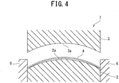
FIG. 4 is a cross-sectional view illustrating a schematic configuration of a press forming device according to a first embodiment; -
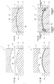
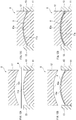
FIGS. 5A to 5D are explanatory views for explaining a press forming method according to the first embodiment; -
FIG. 6 is a graph illustrating a relationship between a ratio L/Lo of a longitudinal length L of a blank material to a longitudinal length Lo of the hat-shaped member and a camber back amount; -
FIG. 7 is a view illustrating a distribution of a stress that acts on a hat-shaped member during press forming; -
FIG. 8 is a view illustrating the camber back that occurs in the hat-shaped member; -
FIG. 9 is a cross-sectional view illustrating a schematic configuration of a second press forming device according to a second embodiment; -
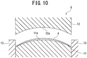
FIG. 10 is a cross-sectional view illustrating a schematic configuration of a first press forming device according to the second embodiment; -
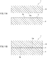
FIGS. 11A and 11B are explanatory views for explaining a press forming method according to the second embodiment; -
FIGS. 12A to 12D are explanatory views for explaining the press forming method according to the second embodiment; -
FIGS. 13A and 13B are views illustrating a configuration of a hat-shaped member according to a modification example; -
FIGS. 14A and 14B are views illustrating a configuration of a U-shaped member according to a modification example; -
FIG. 15 is a view illustrating a configuration of a hat-shaped member according to a modification example; -
FIGS. 16A and 16B are explanatory views for explaining a press forming method according to the modification example; -
FIGS. 17A and 17B are views illustrating a configuration of a hat-shaped member according to examples; and -
FIG. 18A and 18B are tables illustrating evaluation results of the camber back amount and presence of a buckling. - A description is made below of embodiments of the present invention with reference to the drawings.
- First, prior to a description of a press forming method and a method for manufacturing a press formed product according to a first embodiment, a description is made of a camber back occurrence mechanism in general press forming.
- In usual, as illustrated in
FIG. 1 to FIG. 3 , when ablank material 4 is manufactured into a press formed product (hereinafter, also referred to as a "hat-shaped member") 5, which has a hat-shaped cross section and has a bent portion bent to be convex in a direction of atop plate portion 5a, by press forming by using a press forming device 1 (lower die 2, upper die 3), thetop plate portion 5a becomes a portion on an outer bent side (convex side), and accordingly, a longitudinal tensile stress is generated in thetop plate portion 5a. For example, theblank material 4 is a plate-like raw material cut for the press forming. Moreover, for example, the hat-shaped cross section includes one in whichflange portions 5c are further added to a U-shaped cross section having at least thetop plate portion 5a andside wall portions 5b continuous with both sides of thetop plate portion 5a in a width direction (refer toFIG. 2B ). That is to say, the hat-shaped cross section has a cross-sectional shape including at least the U-shaped cross section. Moreover, theflange portions 5c become portions on an inner bent side, and accordingly, a longitudinal compressive stress is generated in theflange portions 5c. - Here,
FIG. 2A illustrates the hat-shapedmember 5 viewed from theside wall portion 5b side, andFIG. 2B illustrates an end surface viewed by cutting the hat-shapedmember 5 on a cross section taken along a line A-A ofFIG. 2A . Moreover,FIG. 3 illustrates an FEM (Finite Element Method) analysis result of the hat-shapedmember 5 viewed from thetop plate portion 5a side. In the example ofFIG. 3 , approximately 500 MPa (tensile stress) is applied to thetop plate portion 5a, and approximately -1200 MPa (compressive stress) is applied to theflange portions 5c. - Therefore, when the hat-shaped
member 5 is released from thelower die 2 and theupper die 3 after the press forming, a bending moment M is generated due to the tensile stress and the compressive stress, and the camber back is generated in the hat-shapedmember 5. In general, the camber back refers to a phenomenon that a material, which is bent, returns to an original shape thereof. - Note that the tensile stress and compressive stress of the hat-shaped
member 5 are increased as strength (yield stress) of theblank material 4 is higher. Therefore, the camber back is increased as strength of theblank material 4 is higher. - The inventor of the present invention thinks that this camber back can be suppressed by reducing the tensile stress generated in the
top plate portion 5a and reducing the bending moment M, and for this suppression, thinks of a press forming method and a method for manufacturing a press formed product, each of which applies a compressive stress, which is reverse to the tensile stress, to thetop plate portion 5a. - Next, a description is made of a configuration of the
press forming device 1 for use in the first embodiment. - As illustrated in
FIG. 4 , thepress forming device 1 of this embodiment includes the lower die and theupper die 3 disposed oppositely to thelower die 2. On an upper surface of thelower die 2, a bent surface (hereinafter, also referred to as a "convex surface") 2a for press forming the bent portion bent upward. Moreover, to theconvex surface 2a, there is further imparted a shape for press forming the hat-shaped cross section, in which thetop plate portion 5a is formed in an upper portion (in a bending direction), and an opening portion is formed in a lower portion therein. Moreover, on a lower surface of theupper die 3, there is formed abent surface 3a (hereinafter, also referred to as a "concave surface 3a") corresponding to a shape of theconvex surface 2a. Then, theupper die 3 approaches thelower die 2 by lifting means (not illustrated), presses theblank material 4, which is interposed between thelower die 2 and theupper die 3, and is thereby capable of press forming the press formed product. In such a way, the hat-shapedmember 5, which has the hat-shaped cross section and has the bent portion bent in the plate thickness direction of thetop plate portion 5a, is press formed (formed). - The
press forming device 1 of this embodiment further includes a pair ofwall portions 6, which are opposed to individual outer peripheries on both longitudinal ends of thelower die 2. The pair ofwall portions 6 are provided apart from each other by a distance equal to a distance between both longitudinal ends of the hat-shapedmember 5 which is already formed. Then, before performing the press forming for theblank material 4 by pressing the same by theupper die 3 and thelower die 2, both longitudinal ends of theblank material 4 are individually allowed to abut against the pair ofwall portions 6, whereby the pair ofwall portions 6 are made capable of fixing (restraining) both longitudinal ends of theblank material 4, that is, capable of suppressing a longitudinal displacement of theblank material 4. - Next, a description is made of a press forming method and a method for manufacturing a press formed product according to the first embodiment.
- First, as illustrated in
FIG. 5A , theblank material 4 is interposed between thelower die 2 and theupper die 3. As theblank material 4, one is adopted, in which at least a longitudinal length (line length) is longer than a longitudinal length (line length) of thetop plate portion 5a of the hat-shapedmember 5, that is, in which the longitudinal length (line length) is longer than a longitudinal length (line length) of theconvex surface 2a and theconcave surface 3a. Here, as illustrated inFIG. 6 , in a range where a ratio L/Lo of the longitudinal length (line length) L of theblank material 4 to the longitudinal length (line length) Lo of the hat-shapedmember 5 is 1.020 (102%) or less, a camber back amount of the hat-shapedmember 5 is reduced as the ratio L/Lo is increased. However, when the ratio L/Lo is increased more than 1.020 (102%), a buckling is generated in a vicinity of each of longitudinal end portions of theblank material 4, and an effect of reducing the camber back disappears. Therefore, the longitudinal length (line length) L of theblank material 4 is set so as to satisfy Lo < L ≤ 1.020×Lo. That is to say, preferably, a difference between the longitudinal length (line length) L of theblank material 4 and the longitudinal length (line length) Lo of the hat-shapedmember 5 is set to 2% or less. - Subsequently, as illustrated in
FIG. 5B , the interposedblank material 4 is warped upward, that is, in the bending direction of thelower die 2 and theupper die 3, both longitudinal ends of theblank material 4 are individually allowed to abut against the pair ofindividual wall portions 6, and individual lower surfaces of both longitudinal ends of theblank material 4 are brought into contact with the upper surface of thelower die 2. In such a way, both longitudinal ends of theblank material 4 are spaced apart from each other by the distance equal to that between both longitudinal ends of the hat-shapedmember 5, and in addition, both longitudinal ends of theblank material 4 are fixed (restrained). At this time, a gap is formed between a head portion of theconvex surface 2a of thelower die 2 and theblank material 4. - Note that, as such a configuration capable of positionally adjusting the pair of
wall portions 6 in an opposite direction, a configuration may be adopted so that, after being once retreated right and left, the pair ofwall portions 6 are allowed to approach each other one more time and to be set to a state ofFIG. 5B . In this case, it is made possible to finely adjust the distance between the pair ofwall portions 6 in matching with the line length of theblank material 4. - Subsequently, as illustrated in
FIG. 5C , theupper die 3 is lowered by the lifting means, and the bent portion is press formed on the fixedblank material 4 by using theconvex surface 2a of thelower die 2 and theconcave surface 3a of theupper die 3. In such a way, theblank material 4 is subjected to the press forming (forming) into the hat-shapedmember 5, which has the hat-shaped cross section and has the bent portion bent upward (in the plate thickness direction of thetop plate portion 5a in the hat-shaped cross section). - During the press forming, as illustrated in
FIG. 5D , the gap between the head portion of theconvex surface 2a of thelower die 2 and theblank material 4 is crushed downward, that is, in an opposite direction to the bending direction of theblank material 4. Then, when the above-described gap is crushed, then as illustrated inFIG. 7 , a longitudinal compressive stress is generated in theblank material 4.FIG. 7 illustrates an FEM analysis result of the hat-shapedmember 5 viewed from thetop plate portion 5a side. In the example ofFIG. 7 , approximately -250 MPa (compressive stress) is applied to thetop plate portion 5a, and approximately -1200 MPa (compressive stress) is applied to theflange portions 5c. - Therefore, when the hat-shaped
member 5 is released from thelower die 2 and theupper die 3 after the press forming, the bending moment M generated in the hat-shapedmember 5 can be reduced. In such a way, as illustrated inFIG. 8 , such a generation amount of the camber back in the hat-shapedmember 5 can be suppressed. Here, in this press forming method, the shape of the hat-shapedmember 5 is not limited. - In the first embodiment, the
lower die 2 and theupper die 3 inFIG. 4 andFIGS. 5A to 5C compose a press die. In general, the press die refers to a "press metal die". - The press forming method according to the first embodiment exerts the following effects.
- (1) In accordance with the press forming method according to the first embodiment, at the time of the press forming, the
blank material 4 in which the longitudinal line length is at least longer than the longitudinal line length of thetop plate portion 5a of the hat-shapedmember 5 is fixed between the pair of press dies (lower die 2, upper die 3), which have the bent surfaces (convex surface 2a,concave surface 3a), while being warped upward, that is, in the bending direction of thelower die 2 and theupper die 3. Subsequently, for the fixedblank material 4, the bent portion of the hat-shapedmember 5 is press formed by using theconvex surface 2a and theconcave surface 3a.
In accordance with the configuration as described above, the gap is formed between the head portion of theconvex surface 2a of thelower die 2 and theblank material 4. Therefore, during the press forming, the gap between the head portion of theconvex surface 2a of thelower die 2 and theblank material 4 is crushed in the opposite direction to the bending direction of theblank material 4, and the compressive stress is generated in the longitudinal direction of theblank material 4. Accordingly, a residual tensile stress in the longitudinal direction on the outer bent side of the hat-shapedmember 5 is reduced, and therefore, the residual bending moment generated in the hat-shapedmember 5 can be reduced. Therefore, the occurrence of the camber back in the hat-shapedmember 5 can be suppressed. In such a way, the camber back that occurs in the hat-shapedmember 5 can be reduced while reducing the restriction on the shape of the hat-shapedmember 5. - (2) In accordance with the press forming method according to the first embodiment, in the event of interposing the
blank material 4 between thelower die 2 and theupper die 3 while warping theblank material 4 in the bending direction of the bent surfaces (convex surface 2a,concave surface 3a) of thelower die 2 and theupper die 3, both longitudinal ends of theblank material 4 are fixed while being spaced apart from each other by the distance equal to that between both longitudinal ends of the hat-shapedmember 5.
In accordance with the configuration as described above, both longitudinal ends of the hat-shapedmember 5 obtained by the press forming can be spaced apart from each other by a more appropriate distance, and accordingly, the hat-shapedmember 5 can be press formed more appropriately. - (3) In accordance with the press forming method according to the first embodiment, in the case where L is the longitudinal line length of the
blank material 4, and Lo is the longitudinal line length of the hat-shapedmember 5, then L and Lo are set so as to satisfy the condition of Lo < L ≤ 1.02×Lo. - In accordance with the configuration as described above, the longitudinal line length of the
blank material 4 can be restricted. Therefore, the reduction of the buckling load of theblank material 4 can be suppressed, and during the press forming, the buckling of theblank material 4 owing to the compressive stress generated in the longitudinal direction of theblank material 4 can be prevented. - Next, a description is made of a second embodiment according to the present invention. Note that the same reference numerals are used for similar constituents and the like to those of the above-described first embodiment, and details thereof are omitted.
- In a press forming method according to the second embodiment, following steps are executed. That is a first forming step of press forming the hat-shaped cross section on the
blank material 4, and a second forming step of press forming the bent portion on theblank material 4 on which the hat-shaped cross section is press formed in the first step. Here, in the first forming step, a firstpress forming device 7 is used. Moreover, in the second forming step, a secondpress forming device 8 is used. - As illustrated in
FIG. 9 , the firstpress forming device 7 includes a lower die and anupper die 10 provided above thelower die 9 so as to be capable of ascending/descending. On an upper surface of thelower die 9, there is formed a shape (hereinafter, also referred to as a "convex surface") 9a for press forming the hat-shaped cross section, in which thetop plate portion 5a is formed in an upper portion, and an opening portion is formed in a lower portion, on theblank material 4. Moreover, on a lower surface of theupper die 10, there is formed a shape (hereinafter, also referred to as a "concave surface") 10a corresponding to the shape of theconvex surface 9a. Then, theupper die 10 is lowered by the lifting means (not illustrated), and presses theblank material 4 interposed between thelower die 9 and theupper die 10. In such a way, the hat-shaped cross section is press formed (formed). - As illustrated in
FIG. 10 , the secondpress forming device 8 includes alower die 11 and anupper die 12 provided above thelower die 11 so as to be capable of ascending/descending. Between thelower die 11 and theupper die 12, theblank material 4 on which the hat-shaped cross section is press formed is interposed while directing thetop plate portion 5a upward and directing the opening portion downward. - On an upper surface of the
lower die 11, there is formed a bent surface (hereinafter, also referred to as a "convex surface") 11a for press forming a bent portion formed by bending theblank material 4, on which the hat-shaped cross section is formed by the firstpress forming device 7, upward (in the direction of thetop plate portion 5a in the hat-shaped cross section). Moreover, on a lower surface of theupper die 12, there is formed a bent surface (hereinafter, also referred to as a "concave surface") 12b corresponding to theconvex surface 2a. Then, theupper die 12 is lowered by the lifting means (not illustrated), and presses theblank material 4 interposed between thelower die 9 and theupper die 12. In such a way, the hat-shapedmember 5, which has the hat-shaped cross section and has the bent portion bent in the plate thickness direction of thetop plate portion 5a, is press formed (formed). - The second
press forming device 8 further includes a pair ofwall portions 13, which are opposed to individual outer peripheries on both longitudinal ends of thelower die 11. The pair ofwall portions 13 are provided apart from each other by a distance equal to the distance between both longitudinal ends of the hat-shapedmember 5. Then, both longitudinal ends of theblank material 4, on which the hat-shaped cross section is formed by the firstpress forming device 7, individually abut against the pair ofwall portions 13, whereby the pair ofwall portions 13 fix (restrain) both longitudinal ends of theblank material 4, that is, suppress a longitudinal displacement of theblank material 4. - Next, a description is made of a press forming method and a method for manufacturing a press formed product according to the second embodiment.
- First, there is executed a first forming step of press forming the hat-shaped cross section on the
blank material 4 by using the firstpress forming device 7. Specifically, first, as illustrated inFIG. 11A , theblank material 4 is mounted on the upper surface of thelower die 9 of the firstpress forming device 7. In a similar way to the first embodiment, as theblank material 4, there is adopted at least one in which a longitudinal length (line length) is longer than the longitudinal length (line length) of thetop plate portion 5a of the hat-shapedmember 5. - Specifically, as the
blank material 4, there is adopted one that satisfies the condition of Lo < L ≤ 1.02 × Lo in the case where L is the longitudinal length (line length) of theblank material 4, and Lo is the longitudinal length (line length) of the hat-shapedmember 5. Subsequently, as illustrated inFIG. 11B , theupper die 10 is lowered to theblank material 4 by the lifting means, and the hat-shaped cross section is press formed (formed) on the mountedblank material 4 by using theconvex surface 9a of thelower die 9 and theconcave surface 10a of theupper die 10. At the time of this press forming, both longitudinal end portions of theblank material 4 are not fixed. - Subsequently, by using the second
press forming device 8, there is executed the second forming step of press forming the bent portion on theblank material 4 on which the hat-shaped cross section is press formed in the first step. Specifically, first, as illustrated inFIG. 12A , theblank material 4 on which the hat-shaped cross section is press formed in the first step is interposed between thelower die 11 and upper die 12 of the secondpress forming device 8. Theblank material 4 on which the hat-shaped cross section is press formed in the first step is interposed while directing thetop plate portion 5a upward and directing the opening portion downward. Subsequently, as illustrated inFIG. 12B , the interposedblank material 4 is warped upward, that is, in the bending direction of thelower die 11 and theupper die 12, both longitudinal ends of theblank material 4 are individually allowed to abut against the pair ofindividual wall portions 13, and individual lower surfaces of both longitudinal ends of theblank material 4 are brought into contact with the upper surface of thelower die 11. In such a way, both longitudinal ends of theblank material 4 are spaced apart from each other by the distance equal to that between both longitudinal ends of the hat-shapedmember 5, and in addition, both longitudinal ends of theblank material 4 are fixed (restrained). Moreover, a gap is formed between a head portion of theconvex surface 11a of thelower die 11 and theblank material 4. - Subsequently, as illustrated in
FIG. 12C , theupper die 12 is lowered by the lifting means, and the bent portion is press formed on the fixedblank material 4 by using theconvex surface 11a of thelower die 11 and theconcave surface 12a of theupper die 12. In such a way, theblank material 4 is subjected to the press forming into the hat-shapedmember 5, which has the hat-shaped cross section and has the bent portion bent upward (in the plate thickness direction of thetop plate portion 5a in the hat-shaped cross section). - During the press forming, as illustrated in
FIG. 12D , the gap between the head portion of theconvex surface 11a of thelower die 11 and theblank material 4 is crushed downward, that is, in an opposite direction to the bending direction of theblank material 4. Then, when the gap is crushed, then a longitudinal compressive stress is generated in theblank material 4. Therefore, when the hat-shapedmember 5 is released from thelower die 11 and theupper die 12 after the press forming, the bending moment M generated in the hat-shapedmember 5 can be reduced. In such a way, an occurrence amount of the camber back in the hat-shapedmember 5 can be suppressed. - In the second embodiment, the
lower die 11 and theupper die 12 inFIG. 10 andFIGS. 12A to 12D compose a press die. In general, the press die refers to a "press metal die". - The press forming method according to the second embodiment exerts the following effects in addition to the effects described in the first embodiment.
- (1) In accordance with the press forming method according to the second embodiment, there is executed the first forming step of press forming the hat-shaped cross section on the
blank material 4 in which the longitudinal length is longer than that of the hat-shapedmember 5. Subsequently, there is executed the second forming step of fixing theblank material 4, on which the hat-shaped cross section is press formed in the first forming step, between the pair of press dies (lower die 11, upper die 12) while warping theblank material 4 in the bending direction of thelower die 11 and theupper die 12, and press forming the bent portion of the hat-shapedmember 5 on the fixedblank material 4 by using the bent surfaces (convex surface 2a,concave surface 3a). - In accordance with the configuration as described above, the forming of the cross-sectional shape and the bending of the
blank material 4 can be realized by different press dies. Therefore, the press dies can be formed simpler in terms of shape. -
- (1) Note that, in the first and second embodiments, the examples of performing the forming as the press forming are illustrated; however, other configurations may be adopted. For example, a configuration of performing draw forming using a wrinkle holder may be adopted.
- (2) Moreover, in the first and second embodiments, there are illustrated the examples of forming the hat-shaped
member 5, which has such a simple hat-shaped cross section as illustrated inFIGS. 2A and 2B , as the formed product; however, other configurations may be adopted. For example, as illustrated inFIGS. 13A and 13B , there may be adopted a configuration of forming a hat-shapedmember 5 having a hat-shaped cross section in which a shape is given to all or a part of thetop plate portion 5a.
Here,FIG. 13A illustrates the hat-shapedmember 5 viewed from theside wall portion 5b side, andFIG. 13B illustrates an end surface viewed by cutting the hat-shapedmember 5 on a cross section taken along a line B-B ofFIG. 13A . Moreover, there may be adopted a configuration of forming a hat-shapedmember 5 having a hat-shaped cross section in which a shape is given to all or a part of theflange portions 5c, and there may be adopted a configuration of forming a hat-shapedmember 5 in which a cross-sectional shape is changed in the longitudinal direction. - (3) Moreover, there is illustrated the example of forming, as the formed product, the hat-shaped
member 5 bent in the height direction of theside wall portion 5b in the hat-shaped cross section, that is, the hat-shapedmember 5 bent when viewed from theside wall portion 5b side; however, other configurations may be adopted. For example, there may be adopted a configuration of forming a hat-shapedmember 5 bent when viewed from thetop plate portion 5a side in addition to being bent when viewed from theside wall portion 5b side. - (4) Moreover, there is illustrated the example of forming, as the formed product, the hat-shaped
member 5 in which thetop plate portion 5a in the hat-shaped cross section is bent as the outer bent side; however, other configurations may be adopted. For example, there may be adopted a configuration of forming a hat-shapedmember 5 in which theflange portions 5c in the hat-shaped cross section are bent as such outer bent sides. - (5) Moreover, in each of the first and second embodiments, there is illustrated the example of press forming, as the formed product, the hat-shaped
member 5 having the hat-shaped cross section having at least thetop plate portion 5a and theside wall portions 5b and theflange portions 5c, which are continuous with both sides thereof in the width direction, and having the bent portion bent in the plate thickness direction of thetop plate portion 5a; however, other configurations may be adopted. For example, as illustrated inFIGS. 14A and 14B , there may be adopted a configuration of forming aU-shaped member 5 having the U-shaped cross section having at least thetop plate portion 5a and theside wall portions 5b continuous with both sides thereof in the width direction, and having the bent portion bent in the plate thickness direction of thetop plate portion 5a.
Here,FIG. 14A illustrates theU-shaped member 5 viewed from theside wall portion 5b side, andFIG. 14B illustrates an end surface viewed by cutting theU-shaped member 5 on a cross section taken along a line C-C ofFIG. 14A . - (6) Moreover, in each of the first and second embodiments, there is illustrated the example of press forming, as the formed product, the hat-shaped
member 5 having the hat-shaped cross section having at least thetop plate portion 5a and theside wall portions 5b and theflange portions 5c, which are continuous with both sides thereof in the width direction, and having the bent portion bent in the plate thickness direction of thetop plate portion 5a, the hat-shapedmember 5 being provided entirely in the longitudinal direction; however, other configurations can also be adopted. - For example, as illustrated in
FIG. 15 , there may be adopted a configuration of press forming, as the formed product, a hat-shapedmember 5 further having non-bent portions (for example, linear portions), which are not bent in the plate thickness direction of thetop plate portion 5a, the hat-shapedmember 5 being provided partially in the longitudinal direction. In this case, theupper die 3 is divided into portions (hereinafter, also referred to as "non-bent-portion dies") 3b for press forming the non-bent portions of the hat-shapedmember 5, and a portion (hereinafter, also referred to as a "bent-portion die") 3c for press forming the bent portion. Then, at the time of the press forming the formed product, the press forming of the non-bent portions is first performed by using the non-bent-portion dies 3b as illustrated inFIG. 16A , and thereafter, the press forming of the curved portion is performed by using the bent-portion die 3c as illustrated inFIG. 16B . In accordance with such a configuration, at the time of the press forming the bent portion after press forming the non-bent portions, theblank material 4 on which the non-bent portions are press formed can be fixed while being warped in the bending direction of the bent surfaces of thelower die 2 and the bent-portion die 3c, and the bent portion can be press formed on the fixedblank material 4 by using thelower die 2 and the bent-portion die 3c. Therefore, the camber back that occurs at the time of press forming the bent portion can be reduced effectively while making it possible to press forming the non-bent portions partially in the longitudinal direction. - A description is made below of an example of the press forming method according to the first embodiment.
- In this example, the press forming method according to the first embodiment was used, and the camber back amount of the hat-shaped
member 5 and presence of the buckling thereof in a case of press forming a hat-shapedmember 5 having a simple hat-shaped cross section illustrated inFIG. 17A were evaluated. The FEM analysis was used for the evaluation of the camber back amount and the presence of the buckling. In the FEM analysis, LS-DYNA version 971 was used as a solver, and an arithmetic operation was performed by using a dynamic explicit method. A mesh size was set to 2 mm, and a friction coefficient was set to 0.12. As a material, an 1180 MPa-class cold-rolled steel sheet with a thickness of 1.2 mm was used. Moreover, a true stress-true strain relationship approximated by the Expression of Swift based on a true stress-true strain curve obtained from JIS No. 5 Tensile Test was used. - As illustrated in
FIG. 18A , in a press forming method ("No. 1" "Comparative example" inFIG. 18A ) in Comparative example, the camber back amount reached 15.5 [mm]. As the press forming method in Comparative example, a press forming method using ablank material 4 in which a longitudinal length (line length) is equal to that of the hat-shapedmember 5 was adopted. In contrast, in press forming methods ("No. 2" "No. 3" "No. 4" "No. 5" "Invention example" inFIG. 18A ) according to the first embodiment, that is, in the press forming methods, each of which uses theblank material 4 in which the longitudinal length (line length) is larger than that of the hat-shapedmember 5, the camber back amounts thereof ranged from 11. 4 [mm] to 3.6 [mm]. In such a way, in the press forming method according to the first embodiment, it was able to be confirmed that the camber back amount that occurs in the hat-shapedmember 5 can be reduced in comparison with the press forming method of Comparative example. - Moreover, as illustrated in No. 6 in
FIG. 18A , in the press forming method according to the first embodiment, it was able to be confirmed that the buckling occurs on both longitudinal ends of the hat-shapedmember 5 when the ratio L/Lo of the longitudinal length (line length) L of theblank material 4 to the longitudinal length (line length) Lo of the hat-shapedmember 5 becomes larger than 1.020. In a similar way, the press forming method according to the first embodiment was used, and the camber back amount of the hat-shapedmember 5 and the presence of the buckling thereof in a case of press forming the hat-shapedmember 5 having such a hat-shaped cross section in which atop plate portion 5a illustrated inFIG. 17 is partially given a shape, were evaluated. In this case, as illustrated in No. 8 to No. 11 inFIG. 18B , with regard to the camber back amount and the presence of the buckling, a similar tendency to that of the hat-shapedmember 5 inFIG. 17A was able to be confirmed also for the hat-shapedmember 5 inFIG. 17B . - The entire contents of
Japanese Patent Application No. 2014-16026 (filed on January 30, 2014 - Here, the description is made while referring to the limited number of embodiments; however, the scope of rights is not limited to these, and for those skilled in the art, modifications of the respective embodiments, which are based on the above-described disclosure, are obvious.
-
- 1
- press forming device
- 2
- lower die (press die)
- 3
- upper die (press die)
- 4
- blank material
- 5
- hat-shaped member
- 6
- wall portion
- 7
- press forming device
- 8
- press forming device
- 11
- lower die (press die)
- 12
- upper die (press die)
- 13
- wall portion
Claims (5)
- A press forming method of press forming a formed product having a U-shaped cross section having at least a top plate portion and side wall portions continuous with both sides of the top plate portion in a width direction, and having a bent portion bent in a plate thickness direction of the top plate portion, the press forming method comprising:fixing a blank material between a pair of press dies, which have bent surfaces for press forming the bent portion of the formed product, while warping the blank material in a bending direction of the bent surfaces of the pair of press dies, the blank material having at least a longer longitudinal line length than a longitudinal line length of the top plate portion of the formed product; andpress forming the bent portion on the fixed blank material by using the bent surfaces of the pair of press dies.
- The press forming method according to claim 1, wherein
the press forming of the bent portion comprises:a first forming step of press forming the U-shaped cross section on the blank material; anda second forming step of fixing the blank material between the pair of press dies while warping the blank material in the bending direction of the bent surfaces of the pair of press dies, the blank material having the U-shaped cross section press formed in the first forming step, and press forming the bent portion on the fixed blank material by using the bent surfaces of the pair of press dies. - The press forming method according to either one of claims 1 and 2, wherein
the formed product further includes a non-bent portion, which is not bent in the plate thickness direction of the top plate portion, partially in a longitudinal direction, and
at a time of press forming the formed product, the press forming of the non-bent portion is first performed, and then the press forming of the bent portion is performed. - The press forming method according to any one of claims 1 to 3, wherein the blank material is fixed while spacing both longitudinal ends of the blank material apart from each other by a distance equal to a distance between both longitudinal ends of the formed product in interposing the blank material between the pair of press dies while warping the blank material in the bending direction of the bent surfaces of the pair of press dies.
- A method for manufacturing a press formed product, the method comprising press forming a formed product having a U-shaped cross section having at least a top plate portion and side wall portions continuous with both sides of the top plate portion in a width direction, and having a bent portion bent in a plate thickness direction of the top plate portion, wherein, the press forming comprises:fixing a blank material between a pair of press dies, which have bent surfaces for press forming the bent portion of the formed product, while warping the blank material in a bending direction of the bent surfaces of the pair of press dies, the blank material having at least a longer longitudinal line length than a longitudinal line length of the top plate portion of the formed product; andpress forming the bent portion on the fixed blank material by using the bent surfaces of the pair of press dies.
Applications Claiming Priority (2)
| Application Number | Priority Date | Filing Date | Title |
|---|---|---|---|
| JP2014016026 | 2014-01-30 | ||
| PCT/JP2015/000301 WO2015115076A1 (en) | 2014-01-30 | 2015-01-23 | Press-forming method and method of manufacturing press-formed product |
Publications (3)
| Publication Number | Publication Date |
|---|---|
| EP3100796A1 true EP3100796A1 (en) | 2016-12-07 |
| EP3100796A4 EP3100796A4 (en) | 2017-03-01 |
| EP3100796B1 EP3100796B1 (en) | 2020-10-28 |
Family
ID=53756658
Family Applications (1)
| Application Number | Title | Priority Date | Filing Date |
|---|---|---|---|
| EP15742980.4A Not-in-force EP3100796B1 (en) | 2014-01-30 | 2015-01-23 | Press-forming method and method of manufacturing press-formed product |
Country Status (7)
| Country | Link |
|---|---|
| US (1) | US10413956B2 (en) |
| EP (1) | EP3100796B1 (en) |
| JP (1) | JP5773109B1 (en) |
| KR (1) | KR101854194B1 (en) |
| CN (1) | CN106061640B (en) |
| MX (1) | MX372885B (en) |
| WO (1) | WO2015115076A1 (en) |
Families Citing this family (6)
| Publication number | Priority date | Publication date | Assignee | Title |
|---|---|---|---|---|
| JP6202189B2 (en) * | 2014-03-04 | 2017-09-27 | 新日鐵住金株式会社 | Press molded product manufacturing method, press molded product manufacturing apparatus, mandrel |
| ES2880625T3 (en) * | 2018-09-11 | 2021-11-25 | Airbus Operations Sl | Methods for the manufacture of curved omega stringers and Z-shaped stringers of composite material and for the manufacture of a stiffened panel of composite material with curvature |
| JP7172917B2 (en) * | 2019-09-02 | 2022-11-16 | トヨタ自動車株式会社 | Manufacturing apparatus and manufacturing method for hat-shaped cross-section part |
| JP2021041447A (en) * | 2019-09-13 | 2021-03-18 | トヨタ自動車株式会社 | Manufacturing equipment and manufacturing method for hat-shaped cross-section parts with curved protrusions |
| CN110899421B (en) * | 2019-12-27 | 2021-09-14 | 卡斯马汽车系统(重庆)有限公司 | Method for bending metal bumper beam and method for bending aluminum alloy bumper beam |
| CN114346592A (en) * | 2021-11-18 | 2022-04-15 | 武汉船用机械有限责任公司 | Machining method of rectangular guide rail workpiece with curved hole |
Family Cites Families (13)
| Publication number | Priority date | Publication date | Assignee | Title |
|---|---|---|---|---|
| BE484869A (en) * | 1947-07-28 | |||
| CN1098034A (en) * | 1994-05-27 | 1995-02-01 | 唐山钢铁(集团)公司 | The method of punching arc sheetmetal |
| JP2002102928A (en) * | 2000-09-28 | 2002-04-09 | Toyota Motor Corp | Press forming method and press forming apparatus |
| JP4004446B2 (en) | 2003-09-17 | 2007-11-07 | コニカミノルタビジネステクノロジーズ株式会社 | Optical element press drawing method and optical element press drawing mold |
| JP4709659B2 (en) * | 2006-02-23 | 2011-06-22 | 新日本製鐵株式会社 | Multi-stage press forming method with excellent shape freezing |
| JP4975386B2 (en) * | 2006-07-11 | 2012-07-11 | 新日本製鐵株式会社 | Multi-stage press forming method with excellent shape freezing property |
| JP4907590B2 (en) * | 2008-04-01 | 2012-03-28 | 新日本製鐵株式会社 | Metal cross-section hat-shaped member having a bent portion outside the plane in the longitudinal direction of the member, and press forming method thereof |
| JP5245755B2 (en) | 2008-11-20 | 2013-07-24 | 日産自動車株式会社 | Press-molded product, press-molded product manufacturing method and manufacturing apparatus |
| JP5353329B2 (en) | 2009-03-12 | 2013-11-27 | 日産自動車株式会社 | Press molding method and press molding apparatus excellent in shape freezing property, and manufacturing method of the press molding apparatus |
| JP2011206789A (en) * | 2010-03-29 | 2011-10-20 | Kobe Steel Ltd | Press forming method |
| JP5987385B2 (en) | 2011-08-30 | 2016-09-07 | Jfeスチール株式会社 | Press molding method of hat-shaped member curved in longitudinal direction |
| KR20130109583A (en) | 2012-03-28 | 2013-10-08 | 주식회사 성우하이텍 | Bending press system |
| JP2014016026A (en) | 2012-06-13 | 2014-01-30 | Toyota Industries Corp | Plate spring and heat dissipation device |
-
2015
- 2015-01-23 KR KR1020167020519A patent/KR101854194B1/en not_active Expired - Fee Related
- 2015-01-23 WO PCT/JP2015/000301 patent/WO2015115076A1/en not_active Ceased
- 2015-01-23 US US15/115,470 patent/US10413956B2/en not_active Expired - Fee Related
- 2015-01-23 EP EP15742980.4A patent/EP3100796B1/en not_active Not-in-force
- 2015-01-23 CN CN201580006556.4A patent/CN106061640B/en not_active Expired - Fee Related
- 2015-01-23 MX MX2016009876A patent/MX372885B/en active IP Right Grant
- 2015-01-23 JP JP2015517517A patent/JP5773109B1/en not_active Expired - Fee Related
Also Published As
| Publication number | Publication date |
|---|---|
| US20170165735A1 (en) | 2017-06-15 |
| WO2015115076A1 (en) | 2015-08-06 |
| JP5773109B1 (en) | 2015-09-02 |
| KR20160103106A (en) | 2016-08-31 |
| KR101854194B1 (en) | 2018-05-04 |
| JPWO2015115076A1 (en) | 2017-03-23 |
| EP3100796A4 (en) | 2017-03-01 |
| CN106061640B (en) | 2018-08-07 |
| MX2016009876A (en) | 2016-10-28 |
| US10413956B2 (en) | 2019-09-17 |
| EP3100796B1 (en) | 2020-10-28 |
| CN106061640A (en) | 2016-10-26 |
| MX372885B (en) | 2020-05-28 |
Similar Documents
| Publication | Publication Date | Title |
|---|---|---|
| EP3100796B1 (en) | Press-forming method and method of manufacturing press-formed product | |
| CA2961188C (en) | Producing method, producing apparatus and producing equipment line of press formed product | |
| KR102291185B1 (en) | Method for manufacturing press-formed products | |
| WO2015072465A1 (en) | Steel plate punching tool and punching method | |
| WO2016136612A1 (en) | Press forming method | |
| EP3272437B1 (en) | Press-forming method and press-forming tool | |
| KR102812727B1 (en) | Press forming method and press formed product | |
| RU2639362C2 (en) | Construction element for motor vehicle body | |
| EP3112041B1 (en) | Press-forming method and press-forming device | |
| CN108698104B (en) | Method for producing press-molded article | |
| CN113226584B (en) | Press forming method | |
| US11260443B2 (en) | Method for manufacturing press formed product | |
| WO2017038579A1 (en) | Method for manufacturing stretch-flange-formed component | |
| US12070787B2 (en) | Press forming method and press apparatus | |
| WO2017149955A1 (en) | Method for manufacturing press molded product | |
| EP3778053A1 (en) | Designing method for press-molded article, press-molding die, press-molded article, and production method for press-molded article | |
| WO2016088519A1 (en) | Press-forming method and method of manufacturing component employing same method, and press-forming device and formed component press-formed using same device | |
| JP6319382B2 (en) | Manufacturing method of stretch flange molded parts | |
| JP6493331B2 (en) | Manufacturing method of press-molded products | |
| JP6176430B1 (en) | Manufacturing method of press-molded products | |
| JP2010094706A (en) | Method for roll bending of aluminum alloy extruded shaped-member, and member made of aluminum alloy extruded shaped-member | |
| JP2002316215A (en) | Method of manufacturing bent article with excellent fatigue property, and bent article |
Legal Events
| Date | Code | Title | Description |
|---|---|---|---|
| PUAI | Public reference made under article 153(3) epc to a published international application that has entered the european phase |
Free format text: ORIGINAL CODE: 0009012 |
|
| STAA | Information on the status of an ep patent application or granted ep patent |
Free format text: STATUS: REQUEST FOR EXAMINATION WAS MADE |
|
| 17P | Request for examination filed |
Effective date: 20160727 |
|
| AK | Designated contracting states |
Kind code of ref document: A1 Designated state(s): AL AT BE BG CH CY CZ DE DK EE ES FI FR GB GR HR HU IE IS IT LI LT LU LV MC MK MT NL NO PL PT RO RS SE SI SK SM TR |
|
| AX | Request for extension of the european patent |
Extension state: BA ME |
|
| A4 | Supplementary search report drawn up and despatched |
Effective date: 20170201 |
|
| RIC1 | Information provided on ipc code assigned before grant |
Ipc: B21D 22/26 20060101AFI20170126BHEP Ipc: B21D 53/88 20060101ALI20170126BHEP |
|
| DAX | Request for extension of the european patent (deleted) | ||
| GRAP | Despatch of communication of intention to grant a patent |
Free format text: ORIGINAL CODE: EPIDOSNIGR1 |
|
| STAA | Information on the status of an ep patent application or granted ep patent |
Free format text: STATUS: GRANT OF PATENT IS INTENDED |
|
| INTG | Intention to grant announced |
Effective date: 20200525 |
|
| GRAS | Grant fee paid |
Free format text: ORIGINAL CODE: EPIDOSNIGR3 |
|
| GRAA | (expected) grant |
Free format text: ORIGINAL CODE: 0009210 |
|
| STAA | Information on the status of an ep patent application or granted ep patent |
Free format text: STATUS: THE PATENT HAS BEEN GRANTED |
|
| AK | Designated contracting states |
Kind code of ref document: B1 Designated state(s): AL AT BE BG CH CY CZ DE DK EE ES FI FR GB GR HR HU IE IS IT LI LT LU LV MC MK MT NL NO PL PT RO RS SE SI SK SM TR |
|
| REG | Reference to a national code |
Ref country code: GB Ref legal event code: FG4D |
|
| REG | Reference to a national code |
Ref country code: CH Ref legal event code: EP |
|
| REG | Reference to a national code |
Ref country code: AT Ref legal event code: REF Ref document number: 1327692 Country of ref document: AT Kind code of ref document: T Effective date: 20201115 |
|
| REG | Reference to a national code |
Ref country code: DE Ref legal event code: R096 Ref document number: 602015061136 Country of ref document: DE |
|
| REG | Reference to a national code |
Ref country code: IE Ref legal event code: FG4D |
|
| REG | Reference to a national code |
Ref country code: DE Ref legal event code: R082 Ref document number: 602015061136 Country of ref document: DE Representative=s name: HL KEMPNER PATENTANWAELTE, SOLICITORS (ENGLAND, DE Ref country code: DE Ref legal event code: R082 Ref document number: 602015061136 Country of ref document: DE Representative=s name: HL KEMPNER PATENTANWALT, RECHTSANWALT, SOLICIT, DE |
|
| REG | Reference to a national code |
Ref country code: AT Ref legal event code: MK05 Ref document number: 1327692 Country of ref document: AT Kind code of ref document: T Effective date: 20201028 |
|
| REG | Reference to a national code |
Ref country code: NL Ref legal event code: MP Effective date: 20201028 |
|
| PG25 | Lapsed in a contracting state [announced via postgrant information from national office to epo] |
Ref country code: RS Free format text: LAPSE BECAUSE OF FAILURE TO SUBMIT A TRANSLATION OF THE DESCRIPTION OR TO PAY THE FEE WITHIN THE PRESCRIBED TIME-LIMIT Effective date: 20201028 Ref country code: PT Free format text: LAPSE BECAUSE OF FAILURE TO SUBMIT A TRANSLATION OF THE DESCRIPTION OR TO PAY THE FEE WITHIN THE PRESCRIBED TIME-LIMIT Effective date: 20210301 Ref country code: FI Free format text: LAPSE BECAUSE OF FAILURE TO SUBMIT A TRANSLATION OF THE DESCRIPTION OR TO PAY THE FEE WITHIN THE PRESCRIBED TIME-LIMIT Effective date: 20201028 Ref country code: NO Free format text: LAPSE BECAUSE OF FAILURE TO SUBMIT A TRANSLATION OF THE DESCRIPTION OR TO PAY THE FEE WITHIN THE PRESCRIBED TIME-LIMIT Effective date: 20210128 Ref country code: NL Free format text: LAPSE BECAUSE OF FAILURE TO SUBMIT A TRANSLATION OF THE DESCRIPTION OR TO PAY THE FEE WITHIN THE PRESCRIBED TIME-LIMIT Effective date: 20201028 Ref country code: GR Free format text: LAPSE BECAUSE OF FAILURE TO SUBMIT A TRANSLATION OF THE DESCRIPTION OR TO PAY THE FEE WITHIN THE PRESCRIBED TIME-LIMIT Effective date: 20210129 |
|
| PGFP | Annual fee paid to national office [announced via postgrant information from national office to epo] |
Ref country code: FR Payment date: 20210108 Year of fee payment: 7 |
|
| REG | Reference to a national code |
Ref country code: LT Ref legal event code: MG4D |
|
| PG25 | Lapsed in a contracting state [announced via postgrant information from national office to epo] |
Ref country code: SE Free format text: LAPSE BECAUSE OF FAILURE TO SUBMIT A TRANSLATION OF THE DESCRIPTION OR TO PAY THE FEE WITHIN THE PRESCRIBED TIME-LIMIT Effective date: 20201028 Ref country code: IS Free format text: LAPSE BECAUSE OF FAILURE TO SUBMIT A TRANSLATION OF THE DESCRIPTION OR TO PAY THE FEE WITHIN THE PRESCRIBED TIME-LIMIT Effective date: 20210228 Ref country code: LV Free format text: LAPSE BECAUSE OF FAILURE TO SUBMIT A TRANSLATION OF THE DESCRIPTION OR TO PAY THE FEE WITHIN THE PRESCRIBED TIME-LIMIT Effective date: 20201028 Ref country code: PL Free format text: LAPSE BECAUSE OF FAILURE TO SUBMIT A TRANSLATION OF THE DESCRIPTION OR TO PAY THE FEE WITHIN THE PRESCRIBED TIME-LIMIT Effective date: 20201028 Ref country code: AT Free format text: LAPSE BECAUSE OF FAILURE TO SUBMIT A TRANSLATION OF THE DESCRIPTION OR TO PAY THE FEE WITHIN THE PRESCRIBED TIME-LIMIT Effective date: 20201028 Ref country code: ES Free format text: LAPSE BECAUSE OF FAILURE TO SUBMIT A TRANSLATION OF THE DESCRIPTION OR TO PAY THE FEE WITHIN THE PRESCRIBED TIME-LIMIT Effective date: 20201028 Ref country code: BG Free format text: LAPSE BECAUSE OF FAILURE TO SUBMIT A TRANSLATION OF THE DESCRIPTION OR TO PAY THE FEE WITHIN THE PRESCRIBED TIME-LIMIT Effective date: 20210128 |
|
| PGFP | Annual fee paid to national office [announced via postgrant information from national office to epo] |
Ref country code: DE Payment date: 20210121 Year of fee payment: 7 Ref country code: GB Payment date: 20210121 Year of fee payment: 7 |
|
| PG25 | Lapsed in a contracting state [announced via postgrant information from national office to epo] |
Ref country code: HR Free format text: LAPSE BECAUSE OF FAILURE TO SUBMIT A TRANSLATION OF THE DESCRIPTION OR TO PAY THE FEE WITHIN THE PRESCRIBED TIME-LIMIT Effective date: 20201028 |
|
| REG | Reference to a national code |
Ref country code: DE Ref legal event code: R097 Ref document number: 602015061136 Country of ref document: DE |
|
| PG25 | Lapsed in a contracting state [announced via postgrant information from national office to epo] |
Ref country code: SK Free format text: LAPSE BECAUSE OF FAILURE TO SUBMIT A TRANSLATION OF THE DESCRIPTION OR TO PAY THE FEE WITHIN THE PRESCRIBED TIME-LIMIT Effective date: 20201028 Ref country code: RO Free format text: LAPSE BECAUSE OF FAILURE TO SUBMIT A TRANSLATION OF THE DESCRIPTION OR TO PAY THE FEE WITHIN THE PRESCRIBED TIME-LIMIT Effective date: 20201028 Ref country code: LT Free format text: LAPSE BECAUSE OF FAILURE TO SUBMIT A TRANSLATION OF THE DESCRIPTION OR TO PAY THE FEE WITHIN THE PRESCRIBED TIME-LIMIT Effective date: 20201028 Ref country code: SM Free format text: LAPSE BECAUSE OF FAILURE TO SUBMIT A TRANSLATION OF THE DESCRIPTION OR TO PAY THE FEE WITHIN THE PRESCRIBED TIME-LIMIT Effective date: 20201028 Ref country code: EE Free format text: LAPSE BECAUSE OF FAILURE TO SUBMIT A TRANSLATION OF THE DESCRIPTION OR TO PAY THE FEE WITHIN THE PRESCRIBED TIME-LIMIT Effective date: 20201028 Ref country code: CZ Free format text: LAPSE BECAUSE OF FAILURE TO SUBMIT A TRANSLATION OF THE DESCRIPTION OR TO PAY THE FEE WITHIN THE PRESCRIBED TIME-LIMIT Effective date: 20201028 |
|
| PG25 | Lapsed in a contracting state [announced via postgrant information from national office to epo] |
Ref country code: DK Free format text: LAPSE BECAUSE OF FAILURE TO SUBMIT A TRANSLATION OF THE DESCRIPTION OR TO PAY THE FEE WITHIN THE PRESCRIBED TIME-LIMIT Effective date: 20201028 Ref country code: MC Free format text: LAPSE BECAUSE OF FAILURE TO SUBMIT A TRANSLATION OF THE DESCRIPTION OR TO PAY THE FEE WITHIN THE PRESCRIBED TIME-LIMIT Effective date: 20201028 |
|
| REG | Reference to a national code |
Ref country code: CH Ref legal event code: PL |
|
| PLBE | No opposition filed within time limit |
Free format text: ORIGINAL CODE: 0009261 |
|
| STAA | Information on the status of an ep patent application or granted ep patent |
Free format text: STATUS: NO OPPOSITION FILED WITHIN TIME LIMIT |
|
| PG25 | Lapsed in a contracting state [announced via postgrant information from national office to epo] |
Ref country code: LU Free format text: LAPSE BECAUSE OF NON-PAYMENT OF DUE FEES Effective date: 20210123 |
|
| 26N | No opposition filed |
Effective date: 20210729 |
|
| REG | Reference to a national code |
Ref country code: BE Ref legal event code: MM Effective date: 20210131 |
|
| PG25 | Lapsed in a contracting state [announced via postgrant information from national office to epo] |
Ref country code: IT Free format text: LAPSE BECAUSE OF FAILURE TO SUBMIT A TRANSLATION OF THE DESCRIPTION OR TO PAY THE FEE WITHIN THE PRESCRIBED TIME-LIMIT Effective date: 20201028 Ref country code: AL Free format text: LAPSE BECAUSE OF FAILURE TO SUBMIT A TRANSLATION OF THE DESCRIPTION OR TO PAY THE FEE WITHIN THE PRESCRIBED TIME-LIMIT Effective date: 20201028 |
|
| PG25 | Lapsed in a contracting state [announced via postgrant information from national office to epo] |
Ref country code: SI Free format text: LAPSE BECAUSE OF FAILURE TO SUBMIT A TRANSLATION OF THE DESCRIPTION OR TO PAY THE FEE WITHIN THE PRESCRIBED TIME-LIMIT Effective date: 20201028 Ref country code: CH Free format text: LAPSE BECAUSE OF NON-PAYMENT OF DUE FEES Effective date: 20210131 Ref country code: LI Free format text: LAPSE BECAUSE OF NON-PAYMENT OF DUE FEES Effective date: 20210131 |
|
| PG25 | Lapsed in a contracting state [announced via postgrant information from national office to epo] |
Ref country code: IE Free format text: LAPSE BECAUSE OF NON-PAYMENT OF DUE FEES Effective date: 20210123 |
|
| PG25 | Lapsed in a contracting state [announced via postgrant information from national office to epo] |
Ref country code: IS Free format text: LAPSE BECAUSE OF FAILURE TO SUBMIT A TRANSLATION OF THE DESCRIPTION OR TO PAY THE FEE WITHIN THE PRESCRIBED TIME-LIMIT Effective date: 20210228 |
|
| PG25 | Lapsed in a contracting state [announced via postgrant information from national office to epo] |
Ref country code: BE Free format text: LAPSE BECAUSE OF NON-PAYMENT OF DUE FEES Effective date: 20210131 |
|
| REG | Reference to a national code |
Ref country code: DE Ref legal event code: R119 Ref document number: 602015061136 Country of ref document: DE |
|
| GBPC | Gb: european patent ceased through non-payment of renewal fee |
Effective date: 20220123 |
|
| PG25 | Lapsed in a contracting state [announced via postgrant information from national office to epo] |
Ref country code: GB Free format text: LAPSE BECAUSE OF NON-PAYMENT OF DUE FEES Effective date: 20220123 Ref country code: DE Free format text: LAPSE BECAUSE OF NON-PAYMENT OF DUE FEES Effective date: 20220802 |
|
| PG25 | Lapsed in a contracting state [announced via postgrant information from national office to epo] |
Ref country code: FR Free format text: LAPSE BECAUSE OF NON-PAYMENT OF DUE FEES Effective date: 20220131 |
|
| PG25 | Lapsed in a contracting state [announced via postgrant information from national office to epo] |
Ref country code: HU Free format text: LAPSE BECAUSE OF FAILURE TO SUBMIT A TRANSLATION OF THE DESCRIPTION OR TO PAY THE FEE WITHIN THE PRESCRIBED TIME-LIMIT; INVALID AB INITIO Effective date: 20150123 |
|
| PG25 | Lapsed in a contracting state [announced via postgrant information from national office to epo] |
Ref country code: CY Free format text: LAPSE BECAUSE OF FAILURE TO SUBMIT A TRANSLATION OF THE DESCRIPTION OR TO PAY THE FEE WITHIN THE PRESCRIBED TIME-LIMIT Effective date: 20201028 |
|
| PG25 | Lapsed in a contracting state [announced via postgrant information from national office to epo] |
Ref country code: MK Free format text: LAPSE BECAUSE OF FAILURE TO SUBMIT A TRANSLATION OF THE DESCRIPTION OR TO PAY THE FEE WITHIN THE PRESCRIBED TIME-LIMIT Effective date: 20201028 |
|
| PG25 | Lapsed in a contracting state [announced via postgrant information from national office to epo] |
Ref country code: MT Free format text: LAPSE BECAUSE OF FAILURE TO SUBMIT A TRANSLATION OF THE DESCRIPTION OR TO PAY THE FEE WITHIN THE PRESCRIBED TIME-LIMIT Effective date: 20201028 |
|
| PG25 | Lapsed in a contracting state [announced via postgrant information from national office to epo] |
Ref country code: TR Free format text: LAPSE BECAUSE OF FAILURE TO SUBMIT A TRANSLATION OF THE DESCRIPTION OR TO PAY THE FEE WITHIN THE PRESCRIBED TIME-LIMIT Effective date: 20201028 |