EP3099889B1 - Bohrlochzugmaschine mit redundanten motorantrieben mit unabhängigen schutzschaltern - Google Patents
Bohrlochzugmaschine mit redundanten motorantrieben mit unabhängigen schutzschaltern Download PDFInfo
- Publication number
- EP3099889B1 EP3099889B1 EP14706703.7A EP14706703A EP3099889B1 EP 3099889 B1 EP3099889 B1 EP 3099889B1 EP 14706703 A EP14706703 A EP 14706703A EP 3099889 B1 EP3099889 B1 EP 3099889B1
- Authority
- EP
- European Patent Office
- Prior art keywords
- power line
- tractor
- current
- drive
- unit
- Prior art date
- Legal status (The legal status is an assumption and is not a legal conclusion. Google has not performed a legal analysis and makes no representation as to the accuracy of the status listed.)
- Active
Links
Images


Classifications
-
- E—FIXED CONSTRUCTIONS
- E21—EARTH OR ROCK DRILLING; MINING
- E21B—EARTH OR ROCK DRILLING; OBTAINING OIL, GAS, WATER, SOLUBLE OR MELTABLE MATERIALS OR A SLURRY OF MINERALS FROM WELLS
- E21B23/00—Apparatus for displacing, setting, locking, releasing or removing tools, packers or the like in boreholes or wells
- E21B23/14—Apparatus for displacing, setting, locking, releasing or removing tools, packers or the like in boreholes or wells for displacing a cable or a cable-operated tool, e.g. for logging or perforating operations in deviated wells
-
- E—FIXED CONSTRUCTIONS
- E21—EARTH OR ROCK DRILLING; MINING
- E21B—EARTH OR ROCK DRILLING; OBTAINING OIL, GAS, WATER, SOLUBLE OR MELTABLE MATERIALS OR A SLURRY OF MINERALS FROM WELLS
- E21B4/00—Drives for drilling, used in the borehole
- E21B4/04—Electric drives
-
- E—FIXED CONSTRUCTIONS
- E21—EARTH OR ROCK DRILLING; MINING
- E21B—EARTH OR ROCK DRILLING; OBTAINING OIL, GAS, WATER, SOLUBLE OR MELTABLE MATERIALS OR A SLURRY OF MINERALS FROM WELLS
- E21B4/00—Drives for drilling, used in the borehole
- E21B4/18—Anchoring or feeding in the borehole
-
- E—FIXED CONSTRUCTIONS
- E21—EARTH OR ROCK DRILLING; MINING
- E21B—EARTH OR ROCK DRILLING; OBTAINING OIL, GAS, WATER, SOLUBLE OR MELTABLE MATERIALS OR A SLURRY OF MINERALS FROM WELLS
- E21B23/00—Apparatus for displacing, setting, locking, releasing or removing tools, packers or the like in boreholes or wells
- E21B23/001—Self-propelling systems or apparatus, e.g. for moving tools within the horizontal portion of a borehole
Definitions
- the present invention relates to a downhole petroleum well tractor for conveying logging or intervention tools in the well. More specifically, the invention relates to an electrically driven downhole petroleum well tractor connected to a surface DC high voltage supply via an electrically conducting logging cable.
- the invention is a downhole petroleum well tractor according to claim 1.
- the invention is also a method for preventing downhole petroleum well tractor failure according to claim 13.
- An advantage of the invention is that by disconnecting the failed motor and motor drive drive it allows the remaining motors to function as normal and the whole tool can continue at reduced performance.
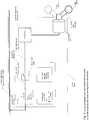
- Fig. 1 is a simplified illustration of a tractor according to the invention with two or more wheel drive sections.
- Each drive section comprises two or more wheels for driving the tractor along a wall in the well, the wall being the borehole wall or an inner wall of a tubing or casing.
- Each wheel drive section is provided with drive wheels driven by brushless DC motors.
- Each brushless DC motor is powered through a DC electronic motor drive connected to a common high voltage power line in the tractor.
- the common high voltage power line of the tractor is connected to a DC line of the logging cable extending from the surface high voltage DC power supply.
- the preferred operating voltage on the common high voltage power line and the electronic motor drives is 600 V.
- the surface power supply may have to operate up to 1200 V in order to try and maintain the desired operating voltage of 600 V and current up to 6 A or more on the common high voltage power line. If the current on the common high voltage power line suddenly drops, the voltage drop over the cable between the surface power supply and the tractor becomes lower. Thus the common high voltage power line may experience peaks or excursions up to 1200 V if the surface high voltage DC power supply does not adjust the voltage down or does not do so fast enough.
- the invention illustrated in Figs. 1 and 2 is downhole petroleum well tractor having a main tractor body, a main body (0) connectable to an electrically conducting logging cable (5) from a surface high voltage DC power supply (50).
- the logging cable (5) is here used as a broad term which may comprise a wireline or intervention cable or a composite rod-like cable with a conductor directly or indirectly connected to the main body's (0) common power line (4) provided with energy supplied from said electrical cable (5).
- the common power line (4) extends through all the wheel drive sections (9) of the tractor.
- the tractor has a connector (01) in its opposite end for mechanically and electrically connecting to conveyed tools.
- the tractor has two or more electrical drive motors (2) supplied with electrical power from said common power line (4) each via a branch power line (40).
- Each said drive motors (2) drives via a drivetrain (62) one or more mechanical drive devices (6) such as drive wheels (6w) or drive belts (6b) for running on and along a wall in a well, such as a borehole wall, a pipe wall, through a valve, etc., for moving said tractor along in the well.
- the tractor is provided with separate circuit breaker units (8) for each said drive motor (2) on each said branch power line (40), please see Fig. 2 and 3 .
- the circuit breaker unit (8) is arranged for monitoring a current (I) to said motor (2) and breaking said current (I) in case said current (I) exceeds a set current level (Imax).
- each said circuit breaker unit (8) is made for disconnecting its associated motor (2) in case said associated motor (2) fails, by detecting an increased current above the set current level, in order to prevent shorting said local HV branch power line (40) thus shorting said HV power line (4). Preventing such a short circuit of power maintains operation of the other motors (2) of the tractor in case one motor fails, resulting in continued operability of the tractor.
- the drive motors (2) are high voltage brushless DC motors.
- each said drive motor (2) comprises a motor drive electronic unit (21) connected to said separate local HV branch power line (40).
- the motor drive electronic unit (21) is a HV DC motor drive electronic unit (21).
- Such brushless motors are provided with an electronic motor drive unit (21) which shapes pulses for driving the motor in a desired direction and at a desired speed.
- the electrical conductor logging cable (5) provides high voltage DC directly or indirectly to the common power line (4) in the tool.
- the surface high voltage DC power supply (50) may provide a voltage between on 300 V to 1800 V, but in an embodiment it provides up to 1200 V to the upper end of the logging cable (5) in order to provide a controlled working voltage of 600 V at the cable head to the common high voltage power line (4) at the tool, including its branch power lines (40).
- the surface DC power supply (50) must be adjusted for its voltage depending on the actually consumed current in the tractor so as for the voltage at the common high voltage power line (4) to be stable at 600V, but a sudden decrease in the consumed current may cause excursions of up to 1200 V at the electrical conductor logging cable (5). It is not desirable to use AC surface power supply because it would incur a considerable inductive resistance in the AC circuit comprising the very long cable in the well.
- the motor drive units are provided with a 30 V input separate from the common high voltage power line (4), for control electronics.
- the circuit breaker (8) unit comprises control means (82, 86, 88) for monitoring said current (I) on said branch power line (40), and arranged for commanding a power switch (84) on said branch power line (40) to break if said current (I) exceeds said set current level (Imax).
- the control means (82, 86, 88) comprising a current meter unit (82) for measuring the current (I) on the high voltage branch power line (40), a threshold comparator unit (86) for comparing said measured current (I) and said set current level (Imax), and a control logic unit (88) for steering said power switch (84) on said high voltage branch power line (40).
- the control logic unit (88) commands high voltage power switch (84) to break the current on branch power line (40).
- Latch means (881) in said control logic unit (88) hold said power switch open if the current on branch power line (40) first has been broken in order to prevent further reconnection of the failed motor(2) and motor drive (21).
- the control logic unit (88) and its latch means (881) may be reset by an operator when the tractor is at the surface so as for enabling testing and reactivation. In an embodiment of the invention it is arranged so as if the power is turned off from the surface completely it will release the latch means (881). This would allow the operator to restart the tool remotely. Should the failure persist the circuit breaker (8) will trip again.
- the current meter unit (82) operates based on measuring a voltage drop over a resistance (823) on said branch power line (40).
- the resistance (823) is low-Ohmic in order to have low power consumption and low heat development of the resistance.
- the current meter unit (82) may comprise a sensor resistance bridge (822) having said sensor resistance (823) connected serially on said local HV power line (40), the differential voltage over said sensor resistance (823) connected to a differential amplifier (824) with an output voltage connected to a first input (861) of said threshold comparator (86), please see Fig. 4 .
- the resistance (823) for being measured for a voltage drop may be constituted by a length of the branch power line (40) itself.
- control means (82, 86, 88) is a low-voltage circuit operating on the high voltage side of said high voltage branch power line (40), such as having an internal low voltage level V e.g. 12 V below said high voltage of said HV branch power line (40), please see Fig. 4 .
- the local low-voltage power supply (89) may comprise a control circuit (891) and connected between apparatus ground (AGND) and said local HV DC power line (40) for controlling said low voltage to said local HV DC circuit breaker and keeping it stable if said HV DC power line (40) varies in voltage, in order to provide stable low voltage to the high voltage circuit breaker (8).
- said HV current meter unit (82) may comprise a magnetic sensor current meter (82m) such as Hall effect sensor or a fluxgate magnetometer based device which measures the magnetic field about the conductor and thus indirectly measures the current on branch HV power line (40).
- a magnetic sensor current meter such as Hall effect sensor or a fluxgate magnetometer based device which measures the magnetic field about the conductor and thus indirectly measures the current on branch HV power line (40).
- Such a magnetic sensor current meter may operate without galvanic contact with the HV power line (40).
- each motor (2) is connected via a transmission drivetrain (62) to said drive device (6).
- Each drive device (6) is preferably arranged on a drive arm (61) which may be hydraulically controlled to be forced against or retracted from the wall onto which the wheel drives.
- the transmission drivetrain may comprise pinion gears and a reduction gear arranged in said arm (61) as sketched in Fig. 2 in order to reduce the motor's high rotational speed of 1500 to 10000 rpm and relatively low torque of 0.5 to 1.5 Nm, geared down 1:50 to 1:150 to a lower desired rotational speed of the wheel and to increase the wheel's torque.
- the well tractor of the invention including its electric motors and said circuit breaker (8) is arranged for operating at well temperatures up to 180 degrees C ambient temperature.
- the invention may be defined as a downhole petroleum well tractor having a main body (0) connectable to an electrical conductor logging cable (5) from a surface high voltage DC power supply (50), characterized by said main body (0) comprising a common HV DC power line (4) provided with high-voltage DC power supplied from said electrical cable (5); two or more HV DC branch power lines (40) from said common HV DC power line (4), each said HV DC branch power line (40) feeding power to a HV motor drive electronic unit (21) for a drive motor (2); each said drive motors (2) driving one or more drive devices (6) such as wheels (6w) drive belts (6b) for running on and along a wall in a well for moving said tractor; separate HV DC circuit breaker units (8) on each said HV DC branch power line (40), each said HVDC circuit breaker (8) unit comprising control means (82, 86, 88) arranged for monitoring a current (I) on said HV DC branch power line (40) and controlling a HV
- Each said HV circuit breaker unit (8) is arranged to disconnect its associated motor (2) in case of said associated motor (2) fails, by detecting an increased current above a set current level, in order to prevent shorting said HV power line (4), thus maintaining operation of the other motors (2) of the tractor.
- the electrical conductor logging cable (5) may be connected directly to said common power line (4).
Landscapes
- Engineering & Computer Science (AREA)
- Life Sciences & Earth Sciences (AREA)
- Geology (AREA)
- Mining & Mineral Resources (AREA)
- Physics & Mathematics (AREA)
- Environmental & Geological Engineering (AREA)
- Fluid Mechanics (AREA)
- General Life Sciences & Earth Sciences (AREA)
- Geochemistry & Mineralogy (AREA)
- Mechanical Engineering (AREA)
- Electric Propulsion And Braking For Vehicles (AREA)
Claims (14)
- Ölbohrlochzugmaschine mit einem Hauptkörper (0), der mit einem elektrisch leitenden Messkabel (5) von einer Hochspannungsgleichstromversorgung (50) an der Oberfläche verbunden werden kann, dadurch gekennzeichnet, dass;
der Hauptkörper (0) Folgendes umfasst
eine gemeinsame Stromleitung (4), die dafür eingerichtet ist, mit Hochspannungsgleichstromenergie aus dem elektrischen Kabel (5) versorgt zu werden, zwei oder mehrere Antriebsmotoren (2), die jeweils mit Strom aus der gemeinsamen Stromleitung (4) über eine separate verzweigte Stromleitung (40) versorgt werden, wobei die gemeinsame Gleichstromleitung (4) und die verzweigte Stromleitung (40) dafür eingerichtet sind, bei einer hohen Spannung zwischen 300 V und 1800 V in Betrieb zu sein, und jeder Antriebsmotor (2) eine elektronische Motorantriebseinheit (21) umfasst, die mit der separaten lokalen verzweigten Hochspannungsstromleitung (40) verbunden ist und eine oder mehrere Antriebsvorrichtungen (6) zum Fahren auf und entlang einer Wand in einem Bohrloch zur Bewegung der Zugmaschine antreibt,
eine separate Leistungsschaltereinheit (8), die auf der verzweigten Stromleitung (40) für jede der zwei oder mehreren Motoren (2) angeordnet ist, wobei die Leistungsschaltereinheiten (8) eine Strommessereinheit (82), die zur Überwachung eines Stroms (I) an den jeweiligen Antriebsmotor (2) auf der verzweigten Stromleitung (40) eingerichtet ist, eine Schwellenwertvergleichereinheit (86), die zum Vergleichen des Stroms (I) mit einem Stromniveau (Imax) eingerichtet ist, und eine Steuerlogikeinheit (88), die zum Befehlen eines Leistungsschalters (84) auf der verzweigten Stromleitung (40) abzuschalten, wenn der Strom (I) das eingestellte Stromniveau (Imax) überschreitet, eingerichtet ist, umfassen. - Bohrlochzugmaschine nach Anspruch 1, wobei die elektronische Motorantriebseinheit (21) eine elektronische Hochspannungsgleichstrommotorantriebseinheit (21) ist.
- Bohrlochzugmaschine nach Anspruch 1, wobei die Strommessereinheit (82) basierend auf einer Messung eines Spannungsabfalls über einen Widerstand (823) auf der verzweigten Stromleitung (40) arbeitet.
- Bohrlochzugmaschine nach Anspruch 1, wobei die Strommessereinheit (82) eine Sensorwiderstandsbrücke (822) umfasst, wobei der Sensorwiderstand (823) auf der lokalen Hochspannungsstromleitung (40) in Reihe geschaltet ist, die Differentialspannung über den Sensorwiderstand (823) mit einem Differentialverstärker (824) verbunden ist, wo eine Ausgangsspannung mit einem ersten Eingang (861) des Schwellenwertvergleichers (86) verbunden ist.
- Bohrlochzugmaschine nach einem der Ansprüche 1 oder 4, wobei die Steuermittel (82, 86, 88) eine Niederspannungsschaltung ist, die auf der Hochspannungsseite der verzweigten Hochspannungsstromleitung (40) arbeitet.
- Bohrlochzugmaschine nach einem der Ansprüche 1 bis 5, wobei die Leistungsschaltereinheit (8) Riegelmittel (881) in der Steuerlogikeinheit (88) umfasst zum Halten des Leistungsschalters (84) in der Abschaltposition, wenn er einmal freigegeben ist.
- Bohrlochzugmaschine nach einem der Ansprüche 1 - 6, wobei die eine oder mehrere Antriebsvorrichtungen (6) Antriebsräder (6w) umfasst.
- Bohrlochzugmaschine nach Anspruch 7, wobei der Hauptkörper (0) zwei oder mehrere Radantriebsabschnitte (9) umfasst, wobei jeder Radantriebsabschnitt (9) eine oder mehrere der elektronischen Motorantriebseinheiten (21) umfasst.
- Bohrlochzugmaschine nach einem der Ansprüche 1 - 8, wobei jeder Motor (2) über einen Übertragungsantriebsstrang (62) mit der Antriebsvorrichtung (6) verbunden ist.
- Bohrlochzugmaschine nach einem der Ansprüche 1 - 9, wobei die Antriebsvorrichtung (6) auf einem Antriebsarm (61) angeordnet ist.
- Bohrlochzugmaschine nach einem der Ansprüche 1 - 18, wobei das eingestellte Stromniveau (Imax) auf der verzweigten Stromleitung (40) im Bereich von 0,5A bis 5A ist.
- Bohrlochzugmaschine-Antriebsmotorleistungsschaltereinheit (8) nach einem der Ansprüche 1 bis 11, wobei
die Leistungsschaltereinheit (8) Riegelmittel (881) in der Steuerlogikeinheit (88) umfasst zum Halten des Leistungsschalters (84) in der Abschaltposition, wenn der Strom in der verzweigten Stromleitung (40) unter das eingestellte Stromniveau (Imax) abfällt, da der Motor (2) und der Motorantrieb (21) jetzt getrennt sind. - Verfahren zum Vorbeugen einer Ölbohrlochzugmaschinestörung, wobei die Zugmaschine einen Hauptkörper (0) aufweist, der mit einem elektrisch leitenden Messkabel (5) von einer Hochspannungsgleichstromversorgung (50) an der Oberfläche verbunden ist, wobei der Hauptkörper (0) Folgendes umfasst
eine gemeinsame Stromleitung (4), die mit Energie aus dem elektrischen Kabel (5) versorgt wird, zwei oder mehrere Antriebsmotoren (2), die jeweils mit Gleichstrom aus der gemeinsamen Stromleitung (4) über eine verzweigte Stromleitung (40) versorgt werden, wobei die gemeinsame Gleichstromleitung (4) und die verzweigte Stromleitung (40) bei einer hohen Spannung zwischen 300 V und 1800 V arbeiten, und jede der Antriebsmotoren (2) eine elektronische Motorantriebseinheit (21) umfasst, die mit der separaten lokalen verzweigten Hochspannungsstromleitung (40) verbunden ist und eine oder mehrere Antriebsvorrichtungen (6) antreibt, die auf und entlang einer Wand in einem Bohrloch zur Bewegung der Zugmaschine fährt bzw. fahren; wobei das Verfahren die folgenden Schritte umfasst;
kontinuierliches Überwachen eines Gleichstroms (I) auf jeder verzweigten Stromleitung (40) durch eine separate Leistungsschaltereinheit (8), und wenn die Leistungsschaltereinheit (8) nachweist, dass der Strom (I) ein eingestelltes Stromniveau (Imax) überschreitet, abschalten des Stroms (I) auf der verzweigten Stromleitung (40) mittels der Leistungsschaltereinheit (8) auf der verzweigten Stromleitung (40),
Überwachen des Stroms (I) auf der verzweigten Stromleitung (40) unter Verwendung einer Strommessereinheit (82), Vergleichen des Werts des gemessenen Stroms (I) mit dem eingestellten Stromniveau (Imax) unter Verwendung einer Schwellenwertvergleichereinheit (86) auf der verzweigten Stromleitung (40) und Anwenden einer Steuerlogikeinheit (88) auf der verzweigten Stromleitung (40) zum Lenken des Leistungsschalters (84) zur Abschaltung des Stroms (I), wenn der gemessene Strom (I) > das eingestellte Stromniveau (I-max) ist. - Verfahren nach Anspruch 13, wobei die Leistungsschaltereinheit (8) Riegelmittel (881) in der Steuerlogikeinheit (88) verwendet zum Halten des Leistungsschalters (84) in der Abschaltposition, wenn er einmal freigegeben ist.
Applications Claiming Priority (1)
| Application Number | Priority Date | Filing Date | Title |
|---|---|---|---|
| PCT/NO2014/000006 WO2015115904A1 (en) | 2014-01-28 | 2014-01-28 | Downhole tractor with redundant motor drives with independent circuit breakers |
Publications (2)
| Publication Number | Publication Date |
|---|---|
| EP3099889A1 EP3099889A1 (de) | 2016-12-07 |
| EP3099889B1 true EP3099889B1 (de) | 2020-07-01 |
Family
ID=50179904
Family Applications (1)
| Application Number | Title | Priority Date | Filing Date |
|---|---|---|---|
| EP14706703.7A Active EP3099889B1 (de) | 2014-01-28 | 2014-01-28 | Bohrlochzugmaschine mit redundanten motorantrieben mit unabhängigen schutzschaltern |
Country Status (5)
| Country | Link |
|---|---|
| US (1) | US10273771B2 (de) |
| EP (1) | EP3099889B1 (de) |
| CA (1) | CA2936911C (de) |
| DK (1) | DK3099889T3 (de) |
| WO (1) | WO2015115904A1 (de) |
Families Citing this family (9)
| Publication number | Priority date | Publication date | Assignee | Title |
|---|---|---|---|---|
| EP2696026A1 (de) * | 2012-08-10 | 2014-02-12 | Welltec A/S | Turbinenbetriebenes Bohrlochsystem |
| NO344602B1 (en) * | 2015-04-01 | 2020-02-10 | Qinterra Tech As | Apparatus for use in a tractor in a wellbore and methods |
| US10424916B2 (en) * | 2016-05-12 | 2019-09-24 | Baker Hughes, A Ge Company, Llc | Downhole component communication and power management |
| US11499372B2 (en) * | 2019-10-28 | 2022-11-15 | Halliburton Energy Services, Inc. | Downhole tractor control systems and methods to adjust a load of a downhole motor |
| NO345947B1 (en) * | 2020-06-03 | 2021-11-08 | Well Innovation As | Pulling tool |
| US11933122B2 (en) * | 2021-07-16 | 2024-03-19 | Halliburton Energy Services, Inc. | Systems and methods for power equalization for multiple downhole tractors |
| US11873690B2 (en) * | 2021-07-16 | 2024-01-16 | Halliburton Energy Services, Inc. | System and methods for power maximization for downhole tractor |
| WO2023061909A1 (en) * | 2021-10-11 | 2023-04-20 | Welltec A/S | Hydraulically driven downhole self-propelling wireline tool |
| US12331603B1 (en) | 2024-07-17 | 2025-06-17 | Halliburton Energy Services, Inc. | Methods and apparatus to decouple downhole tool speed from conveyance tools |
Citations (1)
| Publication number | Priority date | Publication date | Assignee | Title |
|---|---|---|---|---|
| WO2003073182A1 (en) * | 2002-02-25 | 2003-09-04 | General Electric Company | Method and apparatus for optimizing a redundant critical control system |
Family Cites Families (7)
| Publication number | Priority date | Publication date | Assignee | Title |
|---|---|---|---|---|
| US6273189B1 (en) * | 1999-02-05 | 2001-08-14 | Halliburton Energy Services, Inc. | Downhole tractor |
| US8651177B2 (en) * | 2009-08-13 | 2014-02-18 | Smart Drilling And Completion, Inc. | Long-lasting hydraulic seals for smart shuttles, for coiled tubing injectors, and for pipeline pigs |
| US8353348B2 (en) * | 2001-08-19 | 2013-01-15 | Smart Drilling And Completion, Inc. | High power umbilicals for subterranean electric drilling machines and remotely operated vehicles |
| NZ543753A (en) * | 2003-04-24 | 2008-11-28 | Shell Int Research | Thermal processes for subsurface formations |
| US7143843B2 (en) * | 2004-01-05 | 2006-12-05 | Schlumberger Technology Corp. | Traction control for downhole tractor |
| AR064757A1 (es) * | 2007-01-06 | 2009-04-22 | Welltec As | Comunicacion/control de tractor y conmutador de seleccion de disparo perforador |
| US7770667B2 (en) | 2007-06-14 | 2010-08-10 | Wwt International, Inc. | Electrically powered tractor |
-
2014
- 2014-01-28 US US15/112,066 patent/US10273771B2/en active Active
- 2014-01-28 EP EP14706703.7A patent/EP3099889B1/de active Active
- 2014-01-28 DK DK14706703.7T patent/DK3099889T3/da active
- 2014-01-28 WO PCT/NO2014/000006 patent/WO2015115904A1/en not_active Ceased
- 2014-01-28 CA CA2936911A patent/CA2936911C/en active Active
Patent Citations (1)
| Publication number | Priority date | Publication date | Assignee | Title |
|---|---|---|---|---|
| WO2003073182A1 (en) * | 2002-02-25 | 2003-09-04 | General Electric Company | Method and apparatus for optimizing a redundant critical control system |
Also Published As
| Publication number | Publication date |
|---|---|
| US20160333653A1 (en) | 2016-11-17 |
| CA2936911C (en) | 2021-05-11 |
| WO2015115904A1 (en) | 2015-08-06 |
| US10273771B2 (en) | 2019-04-30 |
| EP3099889A1 (de) | 2016-12-07 |
| CA2936911A1 (en) | 2015-08-06 |
| DK3099889T3 (da) | 2020-07-27 |
Similar Documents
| Publication | Publication Date | Title |
|---|---|---|
| US10273771B2 (en) | Downhole tractor with redundant motor drives with independent circuit breakers | |
| US9840907B2 (en) | Data communications system | |
| EP2554785B1 (de) | Sicherheitsventil mit Vorkehrungen zum Antreiben eines Einsetzsicherheitsventils | |
| EP2554786B1 (de) | Elektrisch betätigtes Einsetzsicherheitsventil | |
| CN102005939A (zh) | Ac电源开关模块 | |
| CN105244219B (zh) | 换向式直流断路器及其监视方法 | |
| EP2801695A1 (de) | Elektrische Meeresgrundeinheit und System | |
| AU2014255790B2 (en) | Downhole tool capable of withstanding high temperatures | |
| EP3444426B1 (de) | Lokale stromerzeugung zur zangensteuerung | |
| EP2965402A1 (de) | System und verfahren zum aufladen eines kondensators zur strommessung während eines bohrvorgangs | |
| EP1866671B1 (de) | Bohrloch-signalisierung | |
| AU2011316682B2 (en) | System and method for operating monitoring elements and single use elements with a common cable | |
| CN212435619U (zh) | 一种用于潜油螺杆泵采油系统的保护装置 | |
| AU2021282888A1 (en) | Pulling tool | |
| RU2578678C2 (ru) | Защитное устройство | |
| US20250112457A1 (en) | Current-controlled circuit breaker for electrical submersible pump motor leads | |
| WO2004112212A1 (en) | A method and a device for preventing unintentional connection of a single apparatus to a common energy supply | |
| CN204928101U (zh) | 一种应用于煤矿井下高压开关智能综合保护器装置 | |
| CN201474975U (zh) | 一种螺杆泵断杆保护装置 | |
| CN102092315A (zh) | 一种可控硅自动停送电装置 |
Legal Events
| Date | Code | Title | Description |
|---|---|---|---|
| STAA | Information on the status of an ep patent application or granted ep patent |
Free format text: STATUS: THE INTERNATIONAL PUBLICATION HAS BEEN MADE |
|
| PUAI | Public reference made under article 153(3) epc to a published international application that has entered the european phase |
Free format text: ORIGINAL CODE: 0009012 |
|
| STAA | Information on the status of an ep patent application or granted ep patent |
Free format text: STATUS: REQUEST FOR EXAMINATION WAS MADE |
|
| 17P | Request for examination filed |
Effective date: 20160829 |
|
| AK | Designated contracting states |
Kind code of ref document: A1 Designated state(s): AL AT BE BG CH CY CZ DE DK EE ES FI FR GB GR HR HU IE IS IT LI LT LU LV MC MK MT NL NO PL PT RO RS SE SI SK SM TR |
|
| AX | Request for extension of the european patent |
Extension state: BA ME |
|
| RIN1 | Information on inventor provided before grant (corrected) |
Inventor name: BONDEROVER, EITAN Inventor name: SCHROIT, SAM |
|
| DAX | Request for extension of the european patent (deleted) | ||
| GRAP | Despatch of communication of intention to grant a patent |
Free format text: ORIGINAL CODE: EPIDOSNIGR1 |
|
| STAA | Information on the status of an ep patent application or granted ep patent |
Free format text: STATUS: GRANT OF PATENT IS INTENDED |
|
| INTG | Intention to grant announced |
Effective date: 20200203 |
|
| GRAS | Grant fee paid |
Free format text: ORIGINAL CODE: EPIDOSNIGR3 |
|
| GRAA | (expected) grant |
Free format text: ORIGINAL CODE: 0009210 |
|
| STAA | Information on the status of an ep patent application or granted ep patent |
Free format text: STATUS: THE PATENT HAS BEEN GRANTED |
|
| AK | Designated contracting states |
Kind code of ref document: B1 Designated state(s): AL AT BE BG CH CY CZ DE DK EE ES FI FR GB GR HR HU IE IS IT LI LT LU LV MC MK MT NL NO PL PT RO RS SE SI SK SM TR |
|
| REG | Reference to a national code |
Ref country code: AT Ref legal event code: REF Ref document number: 1286345 Country of ref document: AT Kind code of ref document: T Effective date: 20200715 Ref country code: CH Ref legal event code: EP |
|
| REG | Reference to a national code |
Ref country code: DE Ref legal event code: R096 Ref document number: 602014067200 Country of ref document: DE |
|
| REG | Reference to a national code |
Ref country code: IE Ref legal event code: FG4D |
|
| REG | Reference to a national code |
Ref country code: DK Ref legal event code: T3 Effective date: 20200723 |
|
| REG | Reference to a national code |
Ref country code: NO Ref legal event code: T2 Effective date: 20200701 |
|
| REG | Reference to a national code |
Ref country code: LT Ref legal event code: MG4D |
|
| PG25 | Lapsed in a contracting state [announced via postgrant information from national office to epo] |
Ref country code: BG Free format text: LAPSE BECAUSE OF FAILURE TO SUBMIT A TRANSLATION OF THE DESCRIPTION OR TO PAY THE FEE WITHIN THE PRESCRIBED TIME-LIMIT Effective date: 20201001 |
|
| REG | Reference to a national code |
Ref country code: NL Ref legal event code: MP Effective date: 20200701 |
|
| REG | Reference to a national code |
Ref country code: AT Ref legal event code: MK05 Ref document number: 1286345 Country of ref document: AT Kind code of ref document: T Effective date: 20200701 |
|
| PG25 | Lapsed in a contracting state [announced via postgrant information from national office to epo] |
Ref country code: AT Free format text: LAPSE BECAUSE OF FAILURE TO SUBMIT A TRANSLATION OF THE DESCRIPTION OR TO PAY THE FEE WITHIN THE PRESCRIBED TIME-LIMIT Effective date: 20200701 Ref country code: FI Free format text: LAPSE BECAUSE OF FAILURE TO SUBMIT A TRANSLATION OF THE DESCRIPTION OR TO PAY THE FEE WITHIN THE PRESCRIBED TIME-LIMIT Effective date: 20200701 Ref country code: GR Free format text: LAPSE BECAUSE OF FAILURE TO SUBMIT A TRANSLATION OF THE DESCRIPTION OR TO PAY THE FEE WITHIN THE PRESCRIBED TIME-LIMIT Effective date: 20201002 Ref country code: CZ Free format text: LAPSE BECAUSE OF FAILURE TO SUBMIT A TRANSLATION OF THE DESCRIPTION OR TO PAY THE FEE WITHIN THE PRESCRIBED TIME-LIMIT Effective date: 20200701 Ref country code: HR Free format text: LAPSE BECAUSE OF FAILURE TO SUBMIT A TRANSLATION OF THE DESCRIPTION OR TO PAY THE FEE WITHIN THE PRESCRIBED TIME-LIMIT Effective date: 20200701 Ref country code: ES Free format text: LAPSE BECAUSE OF FAILURE TO SUBMIT A TRANSLATION OF THE DESCRIPTION OR TO PAY THE FEE WITHIN THE PRESCRIBED TIME-LIMIT Effective date: 20200701 Ref country code: PT Free format text: LAPSE BECAUSE OF FAILURE TO SUBMIT A TRANSLATION OF THE DESCRIPTION OR TO PAY THE FEE WITHIN THE PRESCRIBED TIME-LIMIT Effective date: 20201102 Ref country code: SE Free format text: LAPSE BECAUSE OF FAILURE TO SUBMIT A TRANSLATION OF THE DESCRIPTION OR TO PAY THE FEE WITHIN THE PRESCRIBED TIME-LIMIT Effective date: 20200701 Ref country code: LT Free format text: LAPSE BECAUSE OF FAILURE TO SUBMIT A TRANSLATION OF THE DESCRIPTION OR TO PAY THE FEE WITHIN THE PRESCRIBED TIME-LIMIT Effective date: 20200701 |
|
| PG25 | Lapsed in a contracting state [announced via postgrant information from national office to epo] |
Ref country code: IS Free format text: LAPSE BECAUSE OF FAILURE TO SUBMIT A TRANSLATION OF THE DESCRIPTION OR TO PAY THE FEE WITHIN THE PRESCRIBED TIME-LIMIT Effective date: 20201101 Ref country code: LV Free format text: LAPSE BECAUSE OF FAILURE TO SUBMIT A TRANSLATION OF THE DESCRIPTION OR TO PAY THE FEE WITHIN THE PRESCRIBED TIME-LIMIT Effective date: 20200701 Ref country code: RS Free format text: LAPSE BECAUSE OF FAILURE TO SUBMIT A TRANSLATION OF THE DESCRIPTION OR TO PAY THE FEE WITHIN THE PRESCRIBED TIME-LIMIT Effective date: 20200701 Ref country code: PL Free format text: LAPSE BECAUSE OF FAILURE TO SUBMIT A TRANSLATION OF THE DESCRIPTION OR TO PAY THE FEE WITHIN THE PRESCRIBED TIME-LIMIT Effective date: 20200701 |
|
| PG25 | Lapsed in a contracting state [announced via postgrant information from national office to epo] |
Ref country code: NL Free format text: LAPSE BECAUSE OF FAILURE TO SUBMIT A TRANSLATION OF THE DESCRIPTION OR TO PAY THE FEE WITHIN THE PRESCRIBED TIME-LIMIT Effective date: 20200701 |
|
| REG | Reference to a national code |
Ref country code: DE Ref legal event code: R097 Ref document number: 602014067200 Country of ref document: DE |
|
| PG25 | Lapsed in a contracting state [announced via postgrant information from national office to epo] |
Ref country code: SM Free format text: LAPSE BECAUSE OF FAILURE TO SUBMIT A TRANSLATION OF THE DESCRIPTION OR TO PAY THE FEE WITHIN THE PRESCRIBED TIME-LIMIT Effective date: 20200701 Ref country code: RO Free format text: LAPSE BECAUSE OF FAILURE TO SUBMIT A TRANSLATION OF THE DESCRIPTION OR TO PAY THE FEE WITHIN THE PRESCRIBED TIME-LIMIT Effective date: 20200701 Ref country code: IT Free format text: LAPSE BECAUSE OF FAILURE TO SUBMIT A TRANSLATION OF THE DESCRIPTION OR TO PAY THE FEE WITHIN THE PRESCRIBED TIME-LIMIT Effective date: 20200701 Ref country code: EE Free format text: LAPSE BECAUSE OF FAILURE TO SUBMIT A TRANSLATION OF THE DESCRIPTION OR TO PAY THE FEE WITHIN THE PRESCRIBED TIME-LIMIT Effective date: 20200701 |
|
| PLBE | No opposition filed within time limit |
Free format text: ORIGINAL CODE: 0009261 |
|
| STAA | Information on the status of an ep patent application or granted ep patent |
Free format text: STATUS: NO OPPOSITION FILED WITHIN TIME LIMIT |
|
| PG25 | Lapsed in a contracting state [announced via postgrant information from national office to epo] |
Ref country code: AL Free format text: LAPSE BECAUSE OF FAILURE TO SUBMIT A TRANSLATION OF THE DESCRIPTION OR TO PAY THE FEE WITHIN THE PRESCRIBED TIME-LIMIT Effective date: 20200701 |
|
| 26N | No opposition filed |
Effective date: 20210406 |
|
| PG25 | Lapsed in a contracting state [announced via postgrant information from national office to epo] |
Ref country code: SK Free format text: LAPSE BECAUSE OF FAILURE TO SUBMIT A TRANSLATION OF THE DESCRIPTION OR TO PAY THE FEE WITHIN THE PRESCRIBED TIME-LIMIT Effective date: 20200701 |
|
| REG | Reference to a national code |
Ref country code: DE Ref legal event code: R119 Ref document number: 602014067200 Country of ref document: DE |
|
| PG25 | Lapsed in a contracting state [announced via postgrant information from national office to epo] |
Ref country code: SI Free format text: LAPSE BECAUSE OF FAILURE TO SUBMIT A TRANSLATION OF THE DESCRIPTION OR TO PAY THE FEE WITHIN THE PRESCRIBED TIME-LIMIT Effective date: 20200701 Ref country code: MC Free format text: LAPSE BECAUSE OF FAILURE TO SUBMIT A TRANSLATION OF THE DESCRIPTION OR TO PAY THE FEE WITHIN THE PRESCRIBED TIME-LIMIT Effective date: 20200701 |
|
| REG | Reference to a national code |
Ref country code: CH Ref legal event code: PL |
|
| PG25 | Lapsed in a contracting state [announced via postgrant information from national office to epo] |
Ref country code: LU Free format text: LAPSE BECAUSE OF NON-PAYMENT OF DUE FEES Effective date: 20210128 |
|
| REG | Reference to a national code |
Ref country code: BE Ref legal event code: MM Effective date: 20210131 |
|
| PG25 | Lapsed in a contracting state [announced via postgrant information from national office to epo] |
Ref country code: LI Free format text: LAPSE BECAUSE OF NON-PAYMENT OF DUE FEES Effective date: 20210131 Ref country code: CH Free format text: LAPSE BECAUSE OF NON-PAYMENT OF DUE FEES Effective date: 20210131 Ref country code: DE Free format text: LAPSE BECAUSE OF NON-PAYMENT OF DUE FEES Effective date: 20210803 |
|
| PG25 | Lapsed in a contracting state [announced via postgrant information from national office to epo] |
Ref country code: IE Free format text: LAPSE BECAUSE OF NON-PAYMENT OF DUE FEES Effective date: 20210128 |
|
| PG25 | Lapsed in a contracting state [announced via postgrant information from national office to epo] |
Ref country code: BE Free format text: LAPSE BECAUSE OF NON-PAYMENT OF DUE FEES Effective date: 20210131 |
|
| PG25 | Lapsed in a contracting state [announced via postgrant information from national office to epo] |
Ref country code: HU Free format text: LAPSE BECAUSE OF FAILURE TO SUBMIT A TRANSLATION OF THE DESCRIPTION OR TO PAY THE FEE WITHIN THE PRESCRIBED TIME-LIMIT; INVALID AB INITIO Effective date: 20140128 |
|
| PG25 | Lapsed in a contracting state [announced via postgrant information from national office to epo] |
Ref country code: CY Free format text: LAPSE BECAUSE OF FAILURE TO SUBMIT A TRANSLATION OF THE DESCRIPTION OR TO PAY THE FEE WITHIN THE PRESCRIBED TIME-LIMIT Effective date: 20200701 |
|
| PG25 | Lapsed in a contracting state [announced via postgrant information from national office to epo] |
Ref country code: MK Free format text: LAPSE BECAUSE OF FAILURE TO SUBMIT A TRANSLATION OF THE DESCRIPTION OR TO PAY THE FEE WITHIN THE PRESCRIBED TIME-LIMIT Effective date: 20200701 |
|
| PG25 | Lapsed in a contracting state [announced via postgrant information from national office to epo] |
Ref country code: MT Free format text: LAPSE BECAUSE OF FAILURE TO SUBMIT A TRANSLATION OF THE DESCRIPTION OR TO PAY THE FEE WITHIN THE PRESCRIBED TIME-LIMIT Effective date: 20200701 |
|
| PG25 | Lapsed in a contracting state [announced via postgrant information from national office to epo] |
Ref country code: TR Free format text: LAPSE BECAUSE OF FAILURE TO SUBMIT A TRANSLATION OF THE DESCRIPTION OR TO PAY THE FEE WITHIN THE PRESCRIBED TIME-LIMIT Effective date: 20200701 |
|
| PGFP | Annual fee paid to national office [announced via postgrant information from national office to epo] |
Ref country code: GB Payment date: 20251117 Year of fee payment: 13 |
|
| PGFP | Annual fee paid to national office [announced via postgrant information from national office to epo] |
Ref country code: NO Payment date: 20251218 Year of fee payment: 13 |
|
| PGFP | Annual fee paid to national office [announced via postgrant information from national office to epo] |
Ref country code: DK Payment date: 20251118 Year of fee payment: 13 |
|
| PGFP | Annual fee paid to national office [announced via postgrant information from national office to epo] |
Ref country code: FR Payment date: 20251120 Year of fee payment: 13 |