EP3099459B1 - Methods of production of aerated composite materials - Google Patents
Methods of production of aerated composite materials Download PDFInfo
- Publication number
- EP3099459B1 EP3099459B1 EP14837664.3A EP14837664A EP3099459B1 EP 3099459 B1 EP3099459 B1 EP 3099459B1 EP 14837664 A EP14837664 A EP 14837664A EP 3099459 B1 EP3099459 B1 EP 3099459B1
- Authority
- EP
- European Patent Office
- Prior art keywords
- hours
- wet mixture
- mpa
- curing
- range
- Prior art date
- Legal status (The legal status is an assumption and is not a legal conclusion. Google has not performed a legal analysis and makes no representation as to the accuracy of the status listed.)
- Active
Links
Images





Classifications
-
- C—CHEMISTRY; METALLURGY
- C04—CEMENTS; CONCRETE; ARTIFICIAL STONE; CERAMICS; REFRACTORIES
- C04B—LIME, MAGNESIA; SLAG; CEMENTS; COMPOSITIONS THEREOF, e.g. MORTARS, CONCRETE OR LIKE BUILDING MATERIALS; ARTIFICIAL STONE; CERAMICS; REFRACTORIES; TREATMENT OF NATURAL STONE
- C04B28/00—Compositions of mortars, concrete or artificial stone, containing inorganic binders or the reaction product of an inorganic and an organic binder, e.g. polycarboxylate cements
- C04B28/18—Compositions of mortars, concrete or artificial stone, containing inorganic binders or the reaction product of an inorganic and an organic binder, e.g. polycarboxylate cements containing mixtures of the silica-lime type
- C04B28/186—Compositions of mortars, concrete or artificial stone, containing inorganic binders or the reaction product of an inorganic and an organic binder, e.g. polycarboxylate cements containing mixtures of the silica-lime type containing formed Ca-silicates before the final hardening step
- C04B28/188—Compositions of mortars, concrete or artificial stone, containing inorganic binders or the reaction product of an inorganic and an organic binder, e.g. polycarboxylate cements containing mixtures of the silica-lime type containing formed Ca-silicates before the final hardening step the Ca-silicates being present in the starting mixture
-
- B—PERFORMING OPERATIONS; TRANSPORTING
- B28—WORKING CEMENT, CLAY, OR STONE
- B28B—SHAPING CLAY OR OTHER CERAMIC COMPOSITIONS; SHAPING SLAG; SHAPING MIXTURES CONTAINING CEMENTITIOUS MATERIAL, e.g. PLASTER
- B28B1/00—Producing shaped prefabricated articles from the material
- B28B1/50—Producing shaped prefabricated articles from the material specially adapted for producing articles of expanded material, e.g. cellular concrete
-
- B—PERFORMING OPERATIONS; TRANSPORTING
- B28—WORKING CEMENT, CLAY, OR STONE
- B28B—SHAPING CLAY OR OTHER CERAMIC COMPOSITIONS; SHAPING SLAG; SHAPING MIXTURES CONTAINING CEMENTITIOUS MATERIAL, e.g. PLASTER
- B28B11/00—Apparatus or processes for treating or working the shaped or preshaped articles
- B28B11/24—Apparatus or processes for treating or working the shaped or preshaped articles for curing, setting or hardening
- B28B11/245—Curing concrete articles
-
- B—PERFORMING OPERATIONS; TRANSPORTING
- B28—WORKING CEMENT, CLAY, OR STONE
- B28B—SHAPING CLAY OR OTHER CERAMIC COMPOSITIONS; SHAPING SLAG; SHAPING MIXTURES CONTAINING CEMENTITIOUS MATERIAL, e.g. PLASTER
- B28B11/00—Apparatus or processes for treating or working the shaped or preshaped articles
- B28B11/24—Apparatus or processes for treating or working the shaped or preshaped articles for curing, setting or hardening
- B28B11/247—Controlling the humidity during curing, setting or hardening
-
- C—CHEMISTRY; METALLURGY
- C04—CEMENTS; CONCRETE; ARTIFICIAL STONE; CERAMICS; REFRACTORIES
- C04B—LIME, MAGNESIA; SLAG; CEMENTS; COMPOSITIONS THEREOF, e.g. MORTARS, CONCRETE OR LIKE BUILDING MATERIALS; ARTIFICIAL STONE; CERAMICS; REFRACTORIES; TREATMENT OF NATURAL STONE
- C04B2201/00—Mortars, concrete or artificial stone characterised by specific physical values
- C04B2201/50—Mortars, concrete or artificial stone characterised by specific physical values for the mechanical strength
-
- Y—GENERAL TAGGING OF NEW TECHNOLOGICAL DEVELOPMENTS; GENERAL TAGGING OF CROSS-SECTIONAL TECHNOLOGIES SPANNING OVER SEVERAL SECTIONS OF THE IPC; TECHNICAL SUBJECTS COVERED BY FORMER USPC CROSS-REFERENCE ART COLLECTIONS [XRACs] AND DIGESTS
- Y02—TECHNOLOGIES OR APPLICATIONS FOR MITIGATION OR ADAPTATION AGAINST CLIMATE CHANGE
- Y02P—CLIMATE CHANGE MITIGATION TECHNOLOGIES IN THE PRODUCTION OR PROCESSING OF GOODS
- Y02P40/00—Technologies relating to the processing of minerals
- Y02P40/10—Production of cement, e.g. improving or optimising the production methods; Cement grinding
- Y02P40/18—Carbon capture and storage [CCS]
-
- Y—GENERAL TAGGING OF NEW TECHNOLOGICAL DEVELOPMENTS; GENERAL TAGGING OF CROSS-SECTIONAL TECHNOLOGIES SPANNING OVER SEVERAL SECTIONS OF THE IPC; TECHNICAL SUBJECTS COVERED BY FORMER USPC CROSS-REFERENCE ART COLLECTIONS [XRACs] AND DIGESTS
- Y02—TECHNOLOGIES OR APPLICATIONS FOR MITIGATION OR ADAPTATION AGAINST CLIMATE CHANGE
- Y02W—CLIMATE CHANGE MITIGATION TECHNOLOGIES RELATED TO WASTEWATER TREATMENT OR WASTE MANAGEMENT
- Y02W30/00—Technologies for solid waste management
- Y02W30/50—Reuse, recycling or recovery technologies
- Y02W30/91—Use of waste materials as fillers for mortars or concrete
-
- Y—GENERAL TAGGING OF NEW TECHNOLOGICAL DEVELOPMENTS; GENERAL TAGGING OF CROSS-SECTIONAL TECHNOLOGIES SPANNING OVER SEVERAL SECTIONS OF THE IPC; TECHNICAL SUBJECTS COVERED BY FORMER USPC CROSS-REFERENCE ART COLLECTIONS [XRACs] AND DIGESTS
- Y10—TECHNICAL SUBJECTS COVERED BY FORMER USPC
- Y10T—TECHNICAL SUBJECTS COVERED BY FORMER US CLASSIFICATION
- Y10T428/00—Stock material or miscellaneous articles
- Y10T428/249921—Web or sheet containing structurally defined element or component
- Y10T428/249953—Composite having voids in a component [e.g., porous, cellular, etc.]
- Y10T428/249967—Inorganic matrix in void-containing component
- Y10T428/249968—Of hydraulic-setting material
Definitions
- the invention generally relates to methods for producing aerated composite materials and aerated concretes. These aerated composite materials are suitable for a variety of applications in construction, fire resistance and insulation, landscaping, and infrastructure.
- Autoclaved aerated concrete is a type of lightweight, precast concrete that is formed under high temperatures and pressures using raw materials such as cement, fine aggregates such as sand or other filler materials, lime, water, and an aerating agent.
- the aerating agent causes air voids to form in the matrix and increase the porosity of the material, which is accompanied by an increase in the volume of the material along with a reduction in density.
- Aerated concrete products offer a number of advantages over conventional concretes including their good strength, low weight, resistance to fire, corrosion, termite and mold, as well as good thermal insulation and sound deadening properties. Due to its lightweight and dimensional accuracy, aerated concretes can be assembled with minimal waste thereby reducing the need for additional equipment in construction and assembling. They offer high durability and require minimum maintenance. The lightweight of aerated concretes also help with lowering shipping costs.
- aerated concretes are prepared by processes that suffer from a number of deficiencies.
- the manufacture process of conventional aerated concretes involves special equipment, large energy consumption, and excessive carbon dioxide emission, leaving unfavorable carbon footprint.
- aerated concretes are typically cured in autoclaves at temperatures ranging from 150 °C to 190 °C and at pressures ranging from 110 psi to 180 psi, to create a stable form of Tobermorite.
- Tobermorite is the primary binding element in aerated concrete.
- they are relatively expensive due to high finishing costs, difficulty to recycling, etc.
- WO 2012/122031 A discloses a bonding element, a bonding element matrix and composite materials with a wide range of attractive properties that may be optimized, including, but not limited to, mechanical properties, thermal properties, magnetic properties, optical properties and nuclear properties, as a result of a first layer and second layer structure or core, first layer, and second layer structure of the bonding elements, as well as methods for making the bonding elements and the corresponding ceramic and/or composite materials.
- WO 2014/165252 A discloses aerated composite materials that possess excellent physical and performance characteristics of aerated concretes, and methods of production and uses thereof. These composite materials can be readily produced from widely available, low cost raw materials by a process suitable for large-scale production with improved energy consumption, desirable carbon footprint and minimal environmental impact.
- the invention is based in part on the unexpected discovery of manufacturing novel aerated composite materials that possess excellent physical and performance characteristics of aerated concretes. These composite materials can be readily produced from widely available, low cost raw materials by a process suitable for large-scale production with reduced equipment need, improved energy consumption, and more desirable carbon footprint.
- the formulation of aerated composite materials made according to the process of the invention requires mostly readily available and low-cost materials that have minimal environmental impact.
- the raw materials include precursor materials such as particulate calcium silicate (e.g ., ground wollastonite (CS), pseudo-wollastonite, rankinite (C 3 S 2 ), gehlenite (C 2 AS), belite (C 2 S), and alite (C 3 S) where "C” refers to calcium oxide or lime, wherein “S” refers to silicon dioxide or silica, "A” refers to aluminum oxide or alumina according to cement chemist notation (CCN)) along with certain traces of impurities that become bonding elements, and particulate filler materials (e.g ., calcium oxide-containing material such as limestone, xonotlite, miro-silica, and quartz, lightweight aggregates such as perlite or vermiculite, or even industrial waste materials such as fly ash, bottom ash and slag).
- particulate calcium silicate
- an aerating agent e.g., an aluminum powder or paste.
- a fluid component is also provided as a reaction medium, comprising liquid water and/or water vapor and a reagent, carbon dioxide (CO 2 ), which is consumed in the production as a reactive species and ends up sequestered in the final product.
- the bonding elements react at controlled temperatures and pressures either using the process of hydration in which the reaction occurs between water and water vapor, or using water vapor and CO 2 .
- additives such as dispersing, rheology modifying admixtures (to improve mixture consistency), coloring pigments, retarders, and accelerators.
- Additive materials can include natural or recycled materials, and calcium carbonate-rich and magnesium carbonate-rich materials, as well as additives to the fluid component, such as a water-soluble dispersant.
- the aerated composite materials are produced using the efficient gas-assisted hydrothermal liquid phase sintering (HLPS) process at low cost, less demanding equipment, and with much improved energy consumption and carbon footprint.
- HLPS gas-assisted hydrothermal liquid phase sintering
- the invention relates to a process for producing an article of an aerated composite material.
- the process includes: (1) forming a wet mixture, wherein the wet mixture comprises: water, a ground calcium silicate, filler particles, and an aerating agent; (2) casting the wet mixture in a mold; (3) allowing the aerating agent to generate a gaseous product thereby causing volume expansion of the wet mixture; (4) pre-curing the expanded mixture under a pressure ranging from ambient atmospheric pressure to 30 psi (206,843 N/m 2 ), at a temperature in the range from 20°C to 80°C, under an atmosphere of water and CO 2 , under a CO 2 concentration ranging from 25% to 99.5%, and for 1 hour to 10 hours; (5) de-molding and/or cutting the pre-cured object to desired dimensions; and (6) further curing the de-molded and/or cut pre-cured object under a pressure ranging from ambient atmospheric pressure to 30 psi (206,843 N/m 2
- the ground calcium silicate has a specific particle size, d 10 in the range from 0.25 ⁇ m to 5 ⁇ m, d 50 in the range from 5 ⁇ m to 20 ⁇ m, and d 90 in the range of 25 ⁇ m to 100 ⁇ m.
- the filler particles comprise calcium oxide or silica and have a particle size (d 50 ) in the range from 0.25 ⁇ m to 200 ⁇ m.
- the ground calcium silicate includes one or more of synthetic wollastonite, pseudo-wollastonite, rankinite, gehlenite, belite, and alite.
- Also disclosed herein is an article of manufacture produced by a process according to the invention.
- an aerated composite material that includes: (1) a plurality of bonding elements characterized by a specific particle size, d 10 in the range from about 0.25 ⁇ m to about 5 ⁇ m, d 50 in the range from about 5 ⁇ m to about 20 ⁇ m, and d 90 in the range of about 25 ⁇ m to about 100 ⁇ m; (2) a plurality of filler particles having particle sizes in the range from about 0.5 ⁇ m to about 500 ⁇ m; and (3) a plurality of voids.
- Each bonding element comprises: a core comprising primarily calcium silicate, a silica-rich first or inner layer, and a calcium carbonate-rich second or outer layer.
- the plurality of bonding elements and the plurality of filler particles together form one or more bonding matrices and the bonding elements and the filler particles are substantially evenly dispersed therein and bonded together.
- the plurality of voids are bubble-shaped and/or interconnected channels account for from about 50 vol.% to about 80 vol.% of the composite material.
- the aerated composite material exhibits a density from about 300 kg/m 3 to 1500 kg/m 3 , a compressive strength from about 2.0 MPa to about 8.5 MPa, and a flexural strength from about 0.4 MPa to about 1.7 MPa.
- This invention provides a method for producing novel aerated composite materials and products manufactured therefrom that possess excellent physical and performance properties characteristic of aerated concretes but can be readily produced from widely available, low cost raw materials by a process suitable for large-scale production with improved energy consumption, reduced equipment need ( e.g. , without the need for autoclaves), and more desirable carbon footprint.
- the aerated composite materials produced by the method of the invention can be used either in load-bearing or non load-bearing applications.
- the homogeneous nature of their pore structure also imparts superior thermal and acoustic insulation properties compared to conventional aerated concretes.
- the aerated composite materials of the invention can be readily prepared with large dimensions such as a large wall, floor, or roof panels and landscaping blocks.
- the aerated composite materials produced by the method of the invention exhibit excellent insulating qualities (both thermal and sound) as well as fire resistance. They can be produced at large-scales with much improved energy efficiency and more desirable carbon footprint than convention aerated concrete.
- the production of the aerated composite materials consumes CO 2 resulting in CO 2 net sequestration thereby making it carbon-neutral and exceptionally efficient from both financial and environmental conservation perspectives.
- the solid and homogeneous pore structures of these aerated composite materials create airtight building envelopes, minimizing uncontrolled air changes while helping maintain desired indoor temperatures while maximizing the efficiency of HVAC equipment. Additional benefits brought about by the unique aerated composite materials of the invention are reduction of material use, the ability to use recycled products, and avoidance of toxic emissions.
- the invention relates to a process for producing an article of an aerated composite material.
- the process includes: (1) forming a wet mixture, wherein the wet mixture comprises: water, a ground calcium silicate, filler particles, and an aerating agent; (2) casting the wet mixture in a mold; (3) allowing the aerating agent to generate a gaseous product thereby causing volume expansion of the wet mixture; (4) pre-curing the expanded mixture at a temperature in the range from 20°C to 80°C under an atmosphere of water and CO 2 for a time sufficient to result in a pre-cured object suitable for achieving sufficient early-age strength required for de-molding and/or cutting; (5) de-molding and/or cutting the pre-cured object to desired dimensions; and (6) further curing the de-molded and/or cut pre-cured object at a temperature in the range from 20°C to 80°C for 5 hours to 40 hours under an atmosphere of water vapor and CO 2 to yield the article.
- the ground calcium silicate has a specific particle size, d 10 in the range from 0.25 ⁇ m to 5 ⁇ m, d 50 in the range from 5 ⁇ m to 20 ⁇ m, and d 90 in the range of 25 ⁇ m to 100 ⁇ m.
- the filler particles comprise calcium oxide or silica and have a particle size (d 50 ) in the range from 0.25 ⁇ m to 200 ⁇ m.
- the ground calcium silicate includes one or more of synthetic wollastonite, pseudo-wollastonite, rankinite, gehlenite, belite, and alite.
- the wet mixture further includes: a set-controlling agent, a bubble stabilizing agent and a dispersing/viscosity-modifying agent.
- the wet mixture further includes an additive selected from dispersing, rheology modifying admixtures, pigments, retarders, and accelerators.
- forming a wet mixture includes mixing the following ingredients in the specified order of addition: adding a pre-determined portion of water; adding and mixing the set-controlling admixture; adding and mixing the dispersing/viscosity-modifying agent; adding and mixing ground calcium silicate; adding and mixing the filler particles to form a uniform slurry; and adding and mixing the aerating agent.
- the wet mixture comprises mixing the following ingredients in the specified percentages (wt% of the wet mixture): the ground calcium silicate in about 40 wt% to about 95 wt% ( e.g ., about 40 wt% to about 95 wt%, about 50 wt% to about 95 wt%, about 60 wt% to about 95 wt%, about 70 wt% to about 95 wt%, about 40 wt% to about 90 wt%, about 40 wt% to about 80 wt%, about 40 wt% to about 70 wt%, about 40 wt% to about 60 wt%), the filler particles in about 0 wt% to about 30 wt% ( e.g ., about 0 wt% to about 25 wt%, about 0 wt% to about 20 wt%, about 0 wt% to about 15 wt%, about 0 wt% to about 10 wt%
- the first portion of water accounts for about 60% to about 95% (e.g., about 60% to about 90%, about 60% to about 80%, about 60% to about 70%, about 70% to about 95%, about 80% to about 95%, about 90% to about 95%) of and the second portion of water accounts for about 5% to about 40% (e.g., about 5% to about 30%, about 5% to about 20%, about 5% to about 10%, about 10% to about 40%, about 15% to about 40%, about 20% to about 40%, about 30% to about 40%) of total water content in the wet mixture.
- the first portion of water accounts for about 90% of and the second portion of water accounts for about 10% of total water content in the wet mixture.
- Pre-curing the expanded mixture is performed under a pressure ranging from ambient atmospheric pressure to 206,843 N/m 2 (30 psi) above ambient and under a CO 2 concentration ranging from 25% to 99.5% (e.g., from about 50% to 99.5%, from about 60% to 99.5%, from about 70% to 99.5%, from about 80% to 99.5%, from about 90% to 99.5%, from 25% to about 99%, from 25% to about 90%, from 25% to about 80%, from about 50% to about 90%, from about 50% to about 80%, from about 50% to about 60%) to produce an aerated composite material.
- a pressure ranging from ambient atmospheric pressure to 206,843 N/m 2 (30 psi) above ambient and under a CO 2 concentration ranging from 25% to 99.5% (e.g., from about 50% to 99.5%, from about 60% to 99.5%, from about 70% to 99.5%, from about 80% to 99.5%, from about 90% to 99.5%, from 25% to about 99%, from 25% to about 90%
- the pre-curing step is performed at a temperature in the range from 20°C to 80°C (e.g., from 20°C to about 70°C, from 20°C to about 60°C, from about 30°C to 80°C, from about 40°C to 80°C, from about 50°C to 80°C, from about 60°C to 80°C) for 1 hour to 10 hours ( e.g., 1 hour to about 8 hours, 1 hour to about 6 hours, 1 hour to about 4 hours, about 2 hours to 10 hours, about 4 hours to 10 hours, about 6 hours to 10 hours) under a vapor comprising water and CO 2 .
- the pre-curing step is performed at a temperature of about 60°C for 1 hour to about 5 hours ( e.g ., about 2, 3, 4, 5 hours) under a vapor comprising water and CO 2 .
- Further curing the pre-cured object is performed at a temperature in the range from 20°C to 80°C (e.g., from 20°C to about 70°C, from 20°C to about 60°C, from about 30°C to 80°C, from about 40°C to 80°C, from about 50°C to 80°C, from about 60°C to 80°C) for 5 hours to 40 hours ( e.g., 5 hours to about 30 hours, 5 hours to about 20 hours, 5 hours to about 15 hours, about 10 hours to 40 hours, about 15 hours to 40 hours, about 20 hours to 40 hours) under a vapor comprising water and CO 2 and having a pressure in the range from ambient atmospheric pressure to 206,843 N/m 2 (30 psi) above ambient atmospheric pressure ( e.g ., from ambient atmospheric pressure to about 20 psi above ambient atmospheric pressure, from ambient atmospheric pressure to about 10 psi above ambient atmospheric pressure, from about 10 psi above ambient atmospheric pressure to 206,843 N/m 2 (30 ps
- further curing the pre-cured object is performed at a temperature in the range from about 30°C to about 70°C (e.g., from about 30°C to about 60°C, from about 30°C to about 50°C, from about 30°C to about 40°C, from about 40°C to about 70°C, from about 50°C to about 70°C, from about 60°C to about 70°C, from about 30°C to about 60°C) for about 10 hours to about 30 hours ( e.g ., about 10 hours to about 25 hours, about 10 hours to about 20 hours, about 10 hours to about 15 hours, about 15 hours to about 30 hours, about 20 hours to about 30 hours) under a vapor comprising water and CO 2 and having a pressure in the range from ambient atmospheric pressure to 30 psi (206,843 N/m 2 ) above ambient atmospheric pressure, ambient atmospheric pressure to about 20 psi above ambient atmospheric pressure).
- a vapor comprising water and CO 2 under a vapor comprising water and CO 2 and having a pressure
- the pre-curing and further curing is carried out under a dynamic CO 2 circulating flow condition.
- the relative humidity environment of the curing process may be adjusted to fit the desired outcome, for example, ranging from about 50% to about 98% (e.g., from about 60% to about 98%, from about 70% to about 98%, from about 80% to about 98%, from about 90% to about 98%, from about 50% to about 90%, from about 50% to about 80%, from about 50% to about 70%) to produce an aerated composite material exhibiting a uniform, homogeneous, and highly porous structure.
- about 50% to about 98% e.g., from about 60% to about 98%, from about 70% to about 98%, from about 80% to about 98%, from about 90% to about 98%, from about 50% to about 90%, from about 50% to about 80%, from about 50% to about 70%
- the process further includes, after curing the pre-cured object, drying the cured object to remove residual water at a temperature in the range from about 20°C to about 110°C (e.g., from about 20°C to about 100°C, from about 20°C to about 90°C, from about 20°C to about 80°C, from about 20°C to about 70°C, from about 20°C to about 60°C, from about 30°C to about 110°C, from about 40°C to about 110°C, from about 50°C to about 110°C, from about 60°C to about 100°C) for about 12 hours to about 96 hours ( e.g ., about 12 hours to about 72 hours, about 12 hours to about 60 hours, about 12 hours to about 48 hours, about 12 hours to about 36 hours, about 12 hours to about 24 hours, about 24 hours to about 96 hours, about 36 hours to about 96 hours, about 36 hours to about 48 hours).
- about 12 hours to about 72 hours e.g ., about 12 hours to about 60 hours, about 12
- the strength imparting components at the end of the curing process consist primarily of calcium carbonate (CaCO 3 or calcite) along with amorphous calcium-silicate phases, and minor quantities of calcium-silicate hydrate (C-S-H) gel and calcium hydroxide (CH).
- the ground calcium silicate is selected from wollastonite, pseudo-wollastonite, rankanite, belite, and alite.
- the ground calcium silicate or synthetic wollastonite consisting of ground wollastonite (CS) in an equivalent, 1:1, or 2:1 proportion, pseudo-wollastonite, rankinite (C 3 S 2 ), gehlenite (C 2 AS), belite (C 2 S), and alite (C 3 S) where "C” refers to calcium oxide or lime, “S” refers to silicon dioxide or silica, “A” refers to aluminum oxide or alumina according to cement chemist notation (CCN) along with certain traces of impurities.
- CS ground wollastonite
- pseudo-wollastonite rankinite
- C 2 AS gehlenite
- belite C 2 S
- alite C 3 S
- the ground calcium silicate are characterized by d 10 in the range from 0.25 ⁇ m to 5 ⁇ m ( e.g., from 0.25 ⁇ m to about 4 ⁇ m, from 0.25 ⁇ m to about 3 ⁇ m, from 0.25 ⁇ m to about 2 ⁇ m, from 0.25 ⁇ m to about 1 ⁇ m, from about 0.5 ⁇ m to 5 ⁇ m, from about 1 ⁇ m to 5 ⁇ m, from about 2 ⁇ m to 5 ⁇ m), d 50 in the range from 5 ⁇ m to 20 ⁇ m ( e.g., from 5 ⁇ m to about 15 ⁇ m, from 5 ⁇ m to about 10 ⁇ m, from about 10 ⁇ m to 20 ⁇ m, from about 15 ⁇ m to 20 ⁇ m), and d 90 in the range from 25 ⁇ m to 100 ⁇ m ( e.g., 25 ⁇ m to about 80 ⁇ m, 25 ⁇ m to about 70 ⁇ m, 25 ⁇ m to about 60 ⁇ m, 25 ⁇ m
- Exemplary filler particles include lime, quartz (including sand), wollastonite, xonotlite, burned oil shale, fly - or volcanic-ash, stack dust from kilns, ground clay, pumice dust.
- Materials such as industrial waste materials (e.g ., fly ash, slag, silica fume) may also be used as fillers.
- light-weight aggregates such as perlite or vermiculite may also be used as fillers.
- filler particles are made from a calcium oxide-rich material such as ground lime.
- lime refers to naturally occurring or synthetic inorganic materials in which calcium oxide or calcium hydroxide predominate.
- quartz refers to any SiO 2 -based material, including common sands (construction and masonry), as well as glass and recycled glass.
- the term also includes any other recycled natural and synthetic materials that contain significant amounts of SiO 2 (e.g ., mica sometimes formulated as KAl 2 (AlSi 3 O 10 )).
- the filler particles comprise calcium oxide or silica and have a particle size (d 50 ) in the range from 0.25 ⁇ m to 200 ⁇ m ( e.g., from 0.25 ⁇ m to about 150 ⁇ m, from 0.25 ⁇ m to about 100 ⁇ m, from 0.25 ⁇ m to about 50 ⁇ m, from 0.25 ⁇ m to about 20 ⁇ m, from 0.25 ⁇ m to about 10 ⁇ m, from about 0.5 ⁇ m to 200 ⁇ m, from about 1 ⁇ m to 200 ⁇ m, from about 5 ⁇ m to 200 ⁇ m, from about 10 ⁇ m to 200 ⁇ m, from about 20 ⁇ m to 200 ⁇ m, from about 50 ⁇ m to 200 ⁇ m).
- 0.25 ⁇ m to about 150 ⁇ m from 0.25 ⁇ m to about 100 ⁇ m, from 0.25 ⁇ m to about 50 ⁇ m, from 0.25 ⁇ m to about 20 ⁇ m, from 0.25 ⁇ m to about 10 ⁇ m, from about 0.5 ⁇ m to
- the filler particles are selected from fly ash, bottom ash, slag having particle sizes ranging from about 0.5 ⁇ m to about 300 ⁇ m ( e.g., from about 1 ⁇ m to about 300 ⁇ m, from about 5 ⁇ m to about 300 ⁇ m, from about 10 ⁇ m to about 300 ⁇ m, from about 50 ⁇ m to about 300 ⁇ m, from about 100 ⁇ m to about 300 ⁇ m, from about 0.5 ⁇ m to about 200 ⁇ m, from about 0.5 ⁇ m to about 100 ⁇ m, from about 0.5 ⁇ m to about 50 ⁇ m, from about 0.5 ⁇ m to about 20 ⁇ m, from about 0.5 ⁇ m to about 10 ⁇ m, from about 0.5 ⁇ m to about 5 ⁇ m).
- the filler particles are selected from limestone, miro-silica, and quartz having particle sizes ranging from about 1 ⁇ m to about 500 ⁇ m ( e.g., from about 1 ⁇ m to about 400 ⁇ m, from about 1 ⁇ m to about 300 ⁇ m, from about 1 ⁇ m to about 200 ⁇ m, from about 1 ⁇ m to about 100 ⁇ m, from about 1 ⁇ m to about 50 ⁇ m, from about 1 ⁇ m to about 30 ⁇ m, from about 5 ⁇ m to about 500 ⁇ m, from about 10 ⁇ m to about 500 ⁇ m, from about 20 ⁇ m to about 500 ⁇ m, from about 50 ⁇ m to about 500 ⁇ m, from about 100 ⁇ m to about 500 ⁇ m, from about 200 ⁇ m to about 500 ⁇ m).
- ⁇ m to about 500 ⁇ m e.g., from about 1 ⁇ m to about 400 ⁇ m, from about 1 ⁇ m to about 300 ⁇ m, from about 1 ⁇ m to about 200 ⁇ m, from
- the filler particles are selected from lightweight aggregates having particle sizes ranging from about 20 ⁇ m to about 500 ⁇ m ( e.g., from about 20 ⁇ m to about 400 ⁇ m, from about 20 ⁇ m to about 300 ⁇ m, from about 20 ⁇ m to about 200 ⁇ m, from about 20 ⁇ m to about 100 ⁇ m, from about 50 ⁇ m to about 500 ⁇ m, from about 100 ⁇ m to about 500 ⁇ m, from about 200 ⁇ m to about 500 ⁇ m, from about 300 ⁇ m to about 500 ⁇ m).
- the set-controlling admixture is selected from a gluconate and sucrose.
- the dispersing/viscosity-modifying agent is a polycarboxilate based material.
- the ground calcium silicate is ground wollastonite
- the filler particles comprises ground limestone
- the activating-agent is ground lime
- the set-controlling admixture is a gluconate
- the viscosity-modifying agent is a polycarboxilate based material
- the aerating agent is aluminum paste.
- the plurality of voids serve to reduce the overall density of the aerated composite material while at the same time provide a three-dimensional porous network that facilitates uniform and expedited curing of the composite material.
- the plurality of voids may account for any suitable fraction of the overall volume of the aerated composite material dependent on the desired properties and applications at hand. For example, the plurality of voids may account for from about 50 vol.% to about 80 vol.% ( e.g., from about 60 vol.% to about 80 vol.%, from about 65 vol.% to about 80 vol.%, about 60%, about 65%, about 70%, about 75%, about 80%) of the overall volume of the aerated composite material.
- the plurality of voids are caused by a gaseous material generated by an aerating agent.
- the aerating agent includes a metal capable of reacting with acid to generate gaseous hydrogen.
- Exemplary aerating agents include: powder or paste of aluminum, powder of iron, powder of zinc, powder of calcium carbide, and hydrogen peroxide, or a mixture thereof.
- the aerating agents may have any suitable sizes, for example, ranging from about 10 ⁇ m to about 50 ⁇ m ( e.g., from about 10 ⁇ m to 40 ⁇ m, from about 10 ⁇ m to 30 ⁇ m, from about 10 ⁇ m to 20 ⁇ m, from about 15 ⁇ m to 40 ⁇ m, from about 15 ⁇ m to 30 ⁇ m, from about 20 ⁇ m to 40 ⁇ m, larger than about 40 ⁇ m).
- Also disclosed herein is an article of manufacture produced by a process according to the invention.
- the aerated composite material and/or the article of manufacture may be characterized by a density from about 300 kg/m 3 to about 1500 kg/m 3 ( e.g., about 300 kg/m 3 to 1200 kg/m 3 , about 300 kg/m 3 to 1000 kg/m 3 , about 300 kg/m 3 to 900 kg/m 3 , about 400 kg/m 3 to 1200 kg/m 3 , about 400 kg/m 3 to 1000 kg/m 3 , about 400 kg/m 3 to 900 kg/m 3 , about 500 kg/m 3 to 1200 kg/m 3 , about 500 kg/m 3 to 1000 kg/m 3 ).
- the aerated composite materials manufactured according to the process of the invention exhibit excellent compressive strength.
- the aerated composite material and/or the article of manufacture may be characterized by a compressive strength from about 2.0 MPa to about 8.5 MPa (e.g., from about 2.0 MPa to about 6.0 MPa, from about 2.0 MPa to about 5.0 MPa, from about 3.0 MPa to about 8.5 MPa, from about 3.0 MPa to about 6.0 MPa, from about 3.0 MPa to about 5.0 MPa, from about 4.0 MPa to about 8.5 MPa).
- the aerated composite materials manufactured according to the process of the invention also exhibit excellent flexural strength.
- the aerated composite material and/or the article of manufacture may be characterized by a flexural strength from about 0.4 MPa to about 1.7 MPa (e.g., from about 0.7 MPa to about 1.7 MPa, from about 1.0 MPa to about 1.7 MPa, from about 1.2 MPa to about 1.7 MPa, from about 1.0 MPa to about 1.5 MPa, from about 1.2 MPa to about 1.5 MPa).
- the aerated composite material exhibits a density from about 400 kg/m 3 to 1200 kg/m 3 , a compressive strength from about 3.0 MPa to about 6.0 MPa, and a flexural strength from about 0.66 MPa to about 1.32 MPa. In certain embodiments, the aerated composite material exhibits a density from about 500 kg/m 3 to 1000 kg/m 3 , a compressive strength from about 4.0 MPa to about 6.0 MPa, and a flexural strength from about 0.88 MPa to about 1.32 MPa.
- the aerated composite material may be prepared to exhibit a desired density and mechanical properties (e.g ., meeting or exceeding the specifications of strength classes for Aerated Concrete according to ASTM C1693-11).
- Table 1 ASTM Classifications Strength Class Compressive strength Nominal Dry Bulk Density Density Limits psi (MPa) kg/m 3 kg/m 3 minimum Lower limit Upper limit AAC-2 290 (2.0) 350 550 AAC-3 435 (3.0) 450 650 AAC-4 580 (4.0) 450 650 AAC-5 725 (5.0) 550 750 AAC-6 870 (6.0) 550 750
- an aerated composite material that includes: (1) a plurality of bonding elements characterized by a specific particle size, d 10 in the range from about 0.25 ⁇ m to about 5 ⁇ m, d 50 in the range from about 5 ⁇ m to about 20 ⁇ m, and d 90 in the range of about 25 ⁇ m to about 100 ⁇ m; (2) a plurality of filler particles having particle sizes in the range from about 0.5 ⁇ m to about 500 ⁇ m; and (3) a plurality of voids.
- Each bonding element comprises: a core comprising primarily calcium silicate, a silica-rich first or inner layer, and a calcium carbonate-rich second or outer layer.
- the plurality of bonding elements and the plurality of filler particles together form one or more bonding matrices and the bonding elements and the filler particles are substantially evenly dispersed therein and bonded together.
- the plurality of voids are bubble-shaped and/or interconnected channels account for from about 50 vol.% to about 80 vol.% of the composite material.
- the aerated composite material exhibits a density from about 300 kg/m 3 to 1500 kg/m 3 , a compressive strength from about 2.0 MPa to about 8.5 MPa, and a flexural strength from about 0.4 MPa to about 1.7 MPa.
- the plurality of bonding elements are chemically transformed from a precursor calcium silicate other than wollastonite by reacting it with CO 2 via a controlled hydrothermal liquid phase sintering process. In certain embodiments, the plurality of bonding elements are chemically transformed from a precursor calcium silicate comprising one or more of aluminum, magnesium and iron.
- the aerated composite material may further include one or more additives to modify the appearance, physical or mechanical properties of the product.
- additives include rheology modifying admixtures, pigments, retarders, and accelerators.
- a pigment may be evenly dispersed or substantially unevenly dispersed in the bonding matrices, depending on the desired composite material.
- the pigment may be any suitable pigment including, for example, oxides of various metals (e.g. , black iron oxide, cobalt oxide and chromium oxide).
- the pigment may be of any color or colors, for example, selected from black, white, blue, gray, pink, green, red, yellow and brown.
- the pigment may be present in any suitable amount depending on the desired composite material, for example in an amount ranging from about 0.0% to about 10% by weight ( e.g.
- Aerated composite materials manufactured according to the process of the invention may be used to manufacture a wide range of products of various sizes and dimensions including, for example, standard blocks, cored blocks, cladding blocks, shaftwall and fire blocks, lintel blocks, tongue and groove blocks, wall panels, floor panels, roof panels, plates, sidings, frames, fences, decorative and landscaping products, parking stops, etc.
- the variety of products can be produced from widely available, low cost raw materials by a process that does not require autoclaves and is suitable for continuous, large-scale production. The production methods are much improved over conventional aerated concretes in terms of both economics and environmental impact.
- This invention provides apparatus (not claimed) and methods used to manufacture novel composite materials that are cured predominantly by a CO 2 consumption reaction.
- the materials exhibit useful properties and can be readily produced from widely available, low cost precursor materials by a process suitable for large-scale production with minimal environmental impact.
- the precursor materials include inexpensive and abundant calcium silicate rich materials, fine particles and coarse particles.
- the calcium silicate rich materials may be comprised of ground Wollastonite.
- the fine and coarse particles may be comprised of ground limestone or other calcium carbonate based materials, ground quartz or other SiO 2 based materials, sand and crushed rock.
- the fine and coarse particles may also be comprised of crushed minerals such as granite, mica and feldspar.
- Other process components include water and CO 2 .
- additives can be used to modify and fine-tune the physical appearance and/or mechanical properties of the resulting composite material, such as additives selected from one or more of pigments (e.g. , black iron oxide, cobalt oxide and chromium oxide), colored glass and/or colored quartz. Additives regarding water usage reduction and changes in rheology can also be used.
- pigments e.g. , black iron oxide, cobalt oxide and chromium oxide
- the composite materials can be produced, as disclosed herein, using the energy-efficient Hydrothermal Liquid Phase Sintering (HLPS) process to create bonding elements which hold together the various components of the composite material.
- the composite materials can be manufactured at low cost and with favorable environmental impact.
- CO 2 is used as a reactive species resulting in sequestration of CO 2 and the creation of bonding elements in the produced composite materials with in a carbon footprint unmatched by any existing production technology.
- the HLPS process is thermodynamically driven by the free energy of the chemical reaction(s) and reduction of surface energy (area) caused by crystal growth.
- the kinetics of the HLPS process proceed at a reasonable rate at low temperature because a solution (aqueous or nonaqueous) is used to transport reactive species instead of using a high melting point fluid or high temperature solid-state medium.
- calcium silicate refers to naturally-occurring minerals or synthetic materials that are comprised of one or more of a group of calcium-silicon-containing compounds including CS (wollastonite or pseudowollastonite, and sometimes formulated CaSiO 3 or CaO ⁇ SiO 2 ), C3S2 (rankinite, and sometimes formulated as Ca 3 Si 2 O 7 or 3CaO ⁇ 2SiO 2 ), C2S (belite, ⁇ -Ca 2 SiO 4 or larnite, ⁇ -Ca 2 SiO 4 or bredigite, ⁇ -Ca 2 SiO 4 or ⁇ -Ca 2 SiO 4 , and sometimes formulated as Ca 2 SiO 4 or 2CaO ⁇ SiO 2 ), a calcium silicate rich amorphous phase, each of which materials may include one or more other metal ions and oxides ( e.g ., aluminum, magnesium, iron or manganese oxides), or blends thereof, or may include an amount of magnesium
- the calcium-silicon-containing compounds may also include both crystalline and amorphous calcium-silicate phases, which may also comprise of other iron, magnesia, potassium, sodium, and alumina based compounds.
- quartz refers to any SiO 2 -based material, including common sands (construction and masonry), as well as glass and recycled glass.
- the term also includes any other recycled natural and synthetic materials that contain significant amounts of SiO 2 (e.g. , mica sometimes formulated as KAl 2 (AlSi 3 O 10 )(OH) 2 ).
- the composite material is characterized by a compressive strength from about 90 MPa to about 175 MPa (e.g. , about 90 MPa to about 150 MPa, about 90 MPa to about 140 MPa, about 90 MPa to about 130 MPa, about 90 MPa to about 120 MPa, about 90 MPa to about 110 MPa, about 100 MPa to about 175 MPa, about 120 MPa to about 175 MPa, about 130 MPa to about 175 MPa, about 140 MPa to about 175 MPa, about 150 MPa to about 175 MPa, about 160 MPa to about 175 MPa).
- the composite material is characterized by a flexural strength from about 5 MPa to about 30 MPa (e.g. , about 5 MPa to about 25 MPa, about 5 MPa to about 20 MPa, about 5 MPa to about 15 MPa, about 5 MPa to about 10 MPa, about 10 MPa to about 30 MPa, about 20 MPa to about 30 MPa, about 25 MPa to about 30 MPa).
- a flexural strength from about 5 MPa to about 30 MPa (e.g. , about 5 MPa to about 25 MPa, about 5 MPa to about 20 MPa, about 5 MPa to about 15 MPa, about 5 MPa to about 10 MPa, about 10 MPa to about 30 MPa, about 20 MPa to about 30 MPa, about 25 MPa to about 30 MPa).
- the composite material is characterized by water absorption of less than about 10% ( e.g. , less than about 8%, 5%, 4%, 3%, 2%, or 1%).
- the composite material may display one or more of desired textures, patterns and physical properties, in particular those that are characteristic of natural stone.
- the composite material exhibits a visual pattern similar to natural stone.
- Other characteristics include colors (e.g. , black, white, blue, pink, grey (pale to dark), green, red, yellow, brown, cyan (bluish-green) or purple) and textures.
- industrial grade CO 2 at about 99% purity is used, which is provided by a variety of different industrial gas companies, such as Praxair, Inc., Linde AG, Air Liquide, and others.
- This supply can be held in large pressurized holding tanks in the form of liquid carbon dioxide regulated at a temperature such that it maintains a vapor pressure of approximately 300 PSIG.
- This gas is then piped to a CO 2 curing enclosure or chamber.
- CO 2 is flowed through the enclosure at a rate sufficient to displace the ambient air in the enclosure.
- the purge time will depend on the size of the enclosure and the rate that CO 2 gas is provided.
- this process of purging the enclosure of air can be performed in times measured in minutes to get the CO 2 concentration up to a reasonable level so that curing can be performed thereafter.
- CO 2 gas is then fed into the system at a predefined rate so s to maintain a concentration of CO 2 sufficient to drive the curing reaction.
- This method uses the measurement of CO 2 concentration in the system directly, and employs a controller such as a PLC to control the CO 2 concentration at a set point with an electronic/automated control valve.
- a measurement technique to measure CO 2 directly such as NDIR should preferably be employed.
- NDIR measurement method a gas sample stream is pulled from the system via a low flow pump.
- a chiller is used to drop moisture out of the gas stream before it is sampled by the NDIR instrument.
- a measurement of the humidity in the system gas flow can be performed using a dry bulb-wet bulb psychrometric technique, using a dry bulb-wet bulb humidity measurement device or using a different type of moisture sensor.
- the true CO 2 concentration can be calculated using the computer control system or PLC. Once the true CO 2 concentration is known, the actuated proportioning control valve can add dry CO 2 into the system when it has been consumed and has gone below the set point that is desired at that time. In various embodiments, the set point can vary with time, if necessary, based on experience in curing specific compositions, shape and sizes of composite material specimens.
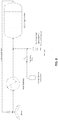
- FIG. 9 is a schematic diagram of a CO 2 composite material curing chamber that provides humidification according to principles of the invention.
- a water supply is provided and water vapor is added to the atmosphere that is circulating within the curing chamber.
- the water can be any convenient source of potable water. In some embodiments, ordinary tap water is used.
- the water can be converted to vapor by flowing through a misting nozzle or an atomizing spray nozzle, an electric vapor generator, a gas fired vapor generator, or by being heated above the gas temperature in the chamber so as to cause evaporation from a liquid water supply an example being a drum reactor with an immersion heater.
- the CO 2 supply can be flowed into the systems after having been bubbled through a heated water supply in order to increase relative humidity of the incoming gas stream an example being a drum reactor configured for "flow through" or "open loop” processing.
- Relative humidity is an important parameter in both traditional concrete curing as well as in CO 2 composite material curing.
- a moist air atmosphere exists that is comprised of mostly nitrogen, oxygen, and water vapor.
- relative humidity is most often measured by a standard capacitive sensor technology.
- CO 2 curing chambers have a gas atmosphere comprised predominately of carbon dioxide that is incompatible with some types of these sensors.
- Sensing technology such as dry-bulb wet-bulb techniques that utilize the psychrometric ratios for carbon dioxide and water vapor or dipole polarization water vapor measurement instruments or chilled mirror hygrometers or capacitive humidity sensors can be used in the CO 2 composite material curing systems described herein.
- the humidity may need to be either decreased or increased and regulated to a specified set point.
- Set points may range anywhere from 1% to 99% relative humidity.
- Three different methods for humidity control may exist in CO 2 composite material curing processes that could be combined into a single system.
- One method for humidification in one embodiment of a CO 2 curing system is represented in FIG. 9 .
- Another method allows one to remove moisture from the system to cure the composite material products with CO 2 .
- a simple method of reducing the relative humidity is by displacing the humid gas in the system with a dry gas, such as carbon dioxide.
- a non-purging method which in one preferred embodiment is a chilled heat exchanger that performs water extraction.
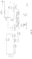
- FIG. 10 is a schematic diagram of a curing chamber with multiple methods of humidity control as well as ability to control and replenish CO 2 using constant flow or pressure regulation and that can control the temperature according to principles of the invention.
- This system is an example of a system that can provide closed loop control or control using feedback, in which set values of operating parameters such as CO 2 concentration, humidity, and temperature that are desired at specific times in the process cycle are provided, and measurements are taken to see whether the actual value of the parameter being controlled is the desired value. If deviation from the desired value is measured, corrective action is taken to bring the value of the parameter into agreement with the desired value.
- Such control systems can be expensive and complex, and may be useful with regard to high value products or products that require very precise process conditions.
- temperature is measured utilizing a sensor such as a thermocouple or an RTD.
- the measurement signal is directed back to a controller or computer that is able to regulate energy into the heat exchanger and thereby adjust the temperature of the entire system over time.
- the blower is an important component of the heating system as it is able to help transfer the heat energy to the gas which transfers to the products and the chamber itself which is an important part of controlled moisture of the samples.
- the method of heating can be electric or gas fired. Jacket heaters may be utilized to control the temperature of the CO 2 that flows through a chamber in contact with the heating jacket, any convenient source of heat can be used.
- the means of external heating may include but are not limited to electric heating, hot water heating, or hot oil heating.
- Another control parameter is gas velocity across the material that is to be cured in the system.
- the gas velocity can be very dependent on process equipment variables including but not limited to chamber design, baffle design, fan size, fan speed/power, number of fans, temperature gradient within the system, rack design within the system, and sample geometry within the system.
- the simplest method to control the gas velocity within the chamber is by adjusting the blower speed (RPM's), typically done by utilization of a variable frequency drive to allow for control of the blower motor speed.
- the blower can be used to circulate gas at a desired velocity in the curing chamber.
- Gas velocity in the system is measured in the system via a variety of different techniques including but not limited to pitot tubes measurement and laser Doppler detection systems.
- the measurement signal for gas velocity can be sent back to a computer system or programmable logic controller and be utilized as a control parameter in the curing profile.
- Any suitable precursor materials may be employed including, for example, calcium silicate composition particles formed from CS (wollastonite or pseudowollastonite, and sometimes formulated CaSiO 3 or CaO ⁇ SiO 2 ), C3S2 (Rankinite, and sometimes formulated as Ca 3 Si 2 O 7 or 3CaO ⁇ 2SiO 2 ), C2S (belite , ⁇ -Ca 2 SiO 4 or larnite, ⁇ -Ca 2 SiO 4 or "bredigite, ⁇ -Ca 2 SiO 4 or ⁇ -Ca 2 SiO 4 , and sometimes formulated as Ca 2 SiO 4 or 2CaO ⁇ SiO 2 ), and a calcium silicate rich amorphous phase.
- CS wollastonite or pseudowollastonite, and sometimes formulated CaSiO 3 or CaO ⁇ SiO 2
- C3S2 Rankinite, and sometimes formulated as Ca 3 Si 2 O 7 or 3CaO ⁇ 2SiO 2
- calcium cations are leached from the calcium silicate composition particles and transform the peripheral portion of the calcium silicate composition particle into calcium-deficient state.
- the structure of the peripheral portion eventually become unstable and breaks down, thereby transforming the calcium-deficient peripheral portion of the particle into a predominantly silica-rich first layer. Meanwhile, a predominantly calcium carbonate second layer precipitates from the water.
- the first layer and second layer may be formed from the precursor particle according the following reactions (1-3) which can use water as a reaction medium, and not as a reagent (that is, the water is not consumed): CaSiO 3 (s) + CO 2 (g) ⁇ CaCO 3 (s) + SiO 2 (s) (1) Ca 3 Si 2 O 7 (s) + 3CO 2 (g) ⁇ 3CaCO 3 (s) + 2SiO 2 (s) (2) Ca 2 SiO 4 (s) + 2CO 2 (g) ⁇ 2CaCO 3 (s) + SiO 2 (s) (3)
- CO 2 is introduced as a gas phase that dissolves into an infiltration fluid, such as water.
- the dissolution of CO 2 forms acidic carbonic species (such as carbonic acid, H 2 CO 3 ) that results in a decrease of pH in solution.
- the weakly acidic solution incongruently dissolves calcium species from the calcium silicate phases.
- Calcium may be leached from calcium containing amorphous phases through a similar mechanism.
- the released calcium cations and the dissociated carbonate species lead to the precipitation of insoluble carbonates.
- Silica-rich layers are thought to remain on the mineral particles as calcium depleted layers.
- CO 2 preferentially reacts with the calcium cations of the calcium silicate composition precursor core, thereby transforming the peripheral portion of the precursor core into a silica-rich first layer and a calcium carbonate-rich second layer. Also, the presence of the first and second layers on the core act as a barrier to further reaction between calcium silicate and carbon dioxide, resulting in the bonding element having the core, first layer and second layer.
- gas-assisted HLPS processes utilize partially infiltrated pore space so as to enable gaseous diffusion to rapidly infiltrate the porous preform and saturate thin liquid interfacial solvent films in the pores with dissolved CO 2 .
- CO 2 -based species have low solubility in pure water (1.5 g/L at 25 °C, 1 atm.).
- a substantial quantity of CO 2 must be continuously supplied to and distributed throughout the porous preform to enable significant carbonate conversion.
- Utilizing gas phase diffusion offers a huge (about 100-fold) increase in diffusion length over that of diffusing soluble CO 2 an equivalent time in a liquid phase.
- Liquid water in the pores speeds up the reaction rate because it provides a medium for ionization of both carbonic acid and calcium species.
- water levels need to be low enough such that CO 2 gas can diffuse into the porous matrix prior to dissolution in the pore-bound water phase.
- the actively dissolving porous preform serves as a template for expansive reactive crystal growth.
- the bonding element and matrices can be formed with minimal distortion and residual stresses. This enables large and complex shapes to result, such as those needed for infrastructure and building materials, in addition to many other applications.
- the time required for curing of a composite material object is determined by the ability of water vapor and CO 2 gas to diffuse throughout the object. In general, thicker objects take longer to cure than thinner objects. Similarly, objects with high density (and fewer open pore spaces) take longer to cure than objects with low density (and more open pore spaces).
- the following table provides examples of how the curing times may vary with respect to the smallest thickness (or wall thickness or section thickness) of the three dimensions and the bulk density of an object that is being manufactured. Table 2 .
- a bonding element includes a core (represented by the black inner portion), a first layer (represented by the white middle portion) and a second or encapsulating layer (represented by the outer portion).
- the first layer may include only one layer or multiple sub-layers and may completely or partially cover the core.
- the first layer may exist in a crystalline phase, an amorphous phase or a mixture thereof, and may be in a continuous phase or as discrete particles.
- the second layer may include only one layer or multiple sub-layers and may also completely or partially cover the first layer.
- the second layer may include a plurality of particles or may be of a continuous phase, with minimal discrete particles.
- a bonding element may exhibit any size and any regular or irregular, solid or hollow morphology depending on the intended application.
- Exemplary morphologies include: cubes, cuboids, prisms, discs, pyramids, polyhedrons or multifaceted particles, cylinders, spheres, cones, rings, tubes, crescents, needles, fibers, filaments, flakes, spheres, sub-spheres, beads, grapes, granulars, oblongs, rods, ripples, etc.
- a bonding element is produced from reactive precursor materials (e.g. , precursor particles) through a transformation process.
- precursor particles may have any size and shape as long as they meet the needs of the intended application.
- the transformation process generally leads to the corresponding bonding elements having similar sizes and shapes of the precursor particles.
- the bonding elements may be positioned, relative to each other, in any one of a number of orientations.
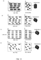
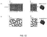
- FIGs. 12(a) - 12(f) schematically illustrate an exemplary bonding matrix that includes fiber- or platelet- shaped bonding elements in different orientations possibly diluted by the incorporation of filler material, as represented by the spacing between the bonding elements.
- FIG. 12(a) illustrates a bonding matrix that includes fiber-shaped bonding elements aligned in a one-direction ("1-D") orientation ( e.g. , aligned with respect to the x direction).
- FIG. 1-D one-direction
- FIG. 12(b) illustrates a bonding matrix that includes platelet-shaped bonding elements aligned in a two-direction ("2-D") orientation (e.g. , aligned with respect to the x and y directions).
- FIG. 12(c) illustrates a bonding matrix that includes platelet-shaped bonding elements aligned in a three-direction ("3-D") orientation ( e.g. , aligned with respect to the x, y and z directions).
- FIG. 12(d) illustrates a bonding matrix that includes platelet-shaped bonding elements in a random orientation, wherein the bonding elements are not aligned with respect to any particular direction.
- FIG. 12(e) illustrates a bonding matrix that includes a relatively high concentration of platelet-shaped bonding elements that are aligned in a 3-D orientation.
- FIG. 12(f) illustrates a bonding matrix that includes a relatively low concentration of platelet- shaped bonding elements that are situated in a random orientation (a percolation network).
- the composite material of FIG. 12(f) achieves the percolation threshold because a large proportion of the bonding elements are touching one another such that a continuous network of contacts are formed from one end of the material to the other end.
- the percolation threshold is the critical concentration above which bonding elements show long-range connectivity with either an ordered, e.g., FIG. 12(e) , or random orientation, e.g., FIG.
- the plurality of bonding elements may be chemically transformed from any suitable precursor materials, for example, from any suitable calcium silicate composition precursor.
- the precursor calcium silicate composition may also include one or more chemical elements of aluminum, magnesium and iron.
- the plurality of bonding elements may have any suitable median particle size and size distribution dependent on the desired composite material.
- the plurality of bonding elements have a median particle size in the range of about 1 ⁇ m to about 100 ⁇ m ( e.g. , about 1 ⁇ m to about 80 ⁇ m, about 1 ⁇ m to about 60 ⁇ m, about 1 ⁇ m to about 50 ⁇ m, about 1 ⁇ m to about 40 ⁇ m, about 1 ⁇ m to about 30 ⁇ m, about 1 ⁇ m to about 20 ⁇ m, about 1 ⁇ m to about 10 ⁇ m, about 5 ⁇ m to about 90 ⁇ m, about 5 ⁇ m to about 80 ⁇ m, about 5 ⁇ m to about 70 ⁇ m, about 5 ⁇ m to about 60 ⁇ m, about 5 ⁇ m to about 50 ⁇ m, about 5 ⁇ m to about 40 ⁇ m, about 10 ⁇ m to about 80 ⁇ m, about 10 ⁇ m to about 70 ⁇ m, about 10 ⁇ m to about 60 ⁇ m,
- a composite material includes: a plurality of bonding elements and a plurality of filler particles.
- Each bonding element includes: a core comprising primarily calcium silicate, a silica-rich first or inner layer, and a calcium carbonate-rich second or outer layer.
- the plurality of bonding elements and the plurality of filler particles together form one or more bonding matrices and the bonding elements and the filler particles are substantially evenly dispersed therein and bonded together, whereby the composite material exhibits one or more textures, patterns and physical properties.
- the filler particles are made from a calcium carbonate-rich material such as limestone (e.g. , ground limestone).
- the filler particles are made from one or more of SiO 2 -based or silicate-based material such as quartz, mica, granite, and feldspar ( e.g. , ground quartz, ground mica, ground granite, ground feldspar).
- Filler particles may include natural, synthetic and recycled materials such as glass, recycled glass, coal slag, calcium carbonate-rich material and magnesium carbonate-rich material.
- the weight ratio of (bonding elements : filler particles) may be any suitable ratios dependent on the desired composite material, for example, in the range of about (10 to 50) : about (50 to 90).
- the composite materials may display various patterns, textures and other characteristics, such as visual patterns of various colors.
- the composite materials of the invention exhibit compressive strength, flexural strength and water absorption properties similar to conventional concrete or the corresponding natural materials.
- the composite may further include a pigment.
- the pigment may be evenly dispersed or substantially unevenly dispersed in the bonding matrices, depending on the desired composite material.
- the pigment may be any suitable pigment including, for example, oxides of various metals ( e.g. , iron oxide, cobalt oxide, chromium oxide)
- the pigment may be of any color or colors, for example, selected from black, white, blue, gray, pink, green, red, yellow and brown.
- the pigment may be present in any suitable amount depending on the desired composite material, for example in an amount ranging from about 0.0% to about 10% by weight ( e.g.
- Example 1 Aerated Composite Material Made Using Synthetic Wollastonite
- Synthetic Wollastonite (SC-C2), Donghai Golden Resources Industries, Donghai, China; Calcium Oxide, Austin, TX (Capitol Brand); Aluminum Paste, Eckrat America Corporation, New Jersey; Glenium 7500, BASF, New Jersey, Filler Materials and Gluconate, Multiple sources. Table 3.
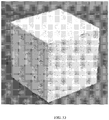
- FIG. 13 shows an example of a cut aerated concrete sample (4 inches x 4 inches x 4 inches for demonstration purpose) made using synthetic wollastonite.
- aerated concretes have been produced using the raw materials and processes mentioned previously having a minimum density of about 525 to 725 kg/m 3 for a corresponding compressive strength of up to 4 MPa. Also, compressive strengths of up to 5.0 MPa have been demonstrated for a density of approximately 850 kg/m 3 . Although these densities and compressive strengths are typical for aerated concretes, the grouping of these materials based on a particular strength class is restricted. The reaction conditions can be further optimized to achieve improved mechanical and performance characteristics.
- the dimensions of the samples used to carry out several trials for the assessment of material performance are 2-inch and 4-inch cubes, along with 4-in by 4-in by 14-in prismatic specimens.
Landscapes
- Chemical & Material Sciences (AREA)
- Engineering & Computer Science (AREA)
- Ceramic Engineering (AREA)
- Structural Engineering (AREA)
- Organic Chemistry (AREA)
- Materials Engineering (AREA)
- Mechanical Engineering (AREA)
- Chemical Kinetics & Catalysis (AREA)
- Inorganic Chemistry (AREA)
- Manufacturing & Machinery (AREA)
- Civil Engineering (AREA)
- Curing Cements, Concrete, And Artificial Stone (AREA)
- Environmental & Geological Engineering (AREA)
- Health & Medical Sciences (AREA)
- Toxicology (AREA)
- Combustion & Propulsion (AREA)
- Molecular Biology (AREA)
- Life Sciences & Earth Sciences (AREA)
- Dispersion Chemistry (AREA)
- Nanotechnology (AREA)
- General Chemical & Material Sciences (AREA)
- Porous Artificial Stone Or Porous Ceramic Products (AREA)
- Preparation Of Compounds By Using Micro-Organisms (AREA)
- Silicates, Zeolites, And Molecular Sieves (AREA)
Description
- The invention generally relates to methods for producing aerated composite materials and aerated concretes. These aerated composite materials are suitable for a variety of applications in construction, fire resistance and insulation, landscaping, and infrastructure.
- Autoclaved aerated concrete is a type of lightweight, precast concrete that is formed under high temperatures and pressures using raw materials such as cement, fine aggregates such as sand or other filler materials, lime, water, and an aerating agent. The aerating agent causes air voids to form in the matrix and increase the porosity of the material, which is accompanied by an increase in the volume of the material along with a reduction in density.
- Aerated concrete products offer a number of advantages over conventional concretes including their good strength, low weight, resistance to fire, corrosion, termite and mold, as well as good thermal insulation and sound deadening properties. Due to its lightweight and dimensional accuracy, aerated concretes can be assembled with minimal waste thereby reducing the need for additional equipment in construction and assembling. They offer high durability and require minimum maintenance. The lightweight of aerated concretes also help with lowering shipping costs.
- Although favorable when compared to concretes, most conventional aerated concretes are prepared by processes that suffer from a number of deficiencies. The manufacture process of conventional aerated concretes involves special equipment, large energy consumption, and excessive carbon dioxide emission, leaving unfavorable carbon footprint. For example, aerated concretes are typically cured in autoclaves at temperatures ranging from 150 °C to 190 °C and at pressures ranging from 110 psi to 180 psi, to create a stable form of Tobermorite. Tobermorite is the primary binding element in aerated concrete. In addition, they are relatively expensive due to high finishing costs, difficulty to recycling, etc.
- There is an on-going need for novel aerated composite materials that match or exceed the physical and performance characteristics of aerated concretes that can be mass-produced at lower cost with improved energy consumption and more desirable carbon footprint.
WO 2012/122031 A discloses a bonding element, a bonding element matrix and composite materials with a wide range of attractive properties that may be optimized, including, but not limited to, mechanical properties, thermal properties, magnetic properties, optical properties and nuclear properties, as a result of a first layer and second layer structure or core, first layer, and second layer structure of the bonding elements, as well as methods for making the bonding elements and the corresponding ceramic and/or composite materials.
WO 2014/165252 A (relevant under Article 54(3) EPC only) discloses aerated composite materials that possess excellent physical and performance characteristics of aerated concretes, and methods of production and uses thereof. These composite materials can be readily produced from widely available, low cost raw materials by a process suitable for large-scale production with improved energy consumption, desirable carbon footprint and minimal environmental impact. - The invention is based in part on the unexpected discovery of manufacturing novel aerated composite materials that possess excellent physical and performance characteristics of aerated concretes. These composite materials can be readily produced from widely available, low cost raw materials by a process suitable for large-scale production with reduced equipment need, improved energy consumption, and more desirable carbon footprint.
- The formulation of aerated composite materials made according to the process of the invention requires mostly readily available and low-cost materials that have minimal environmental impact. The raw materials include precursor materials such as particulate calcium silicate (e.g., ground wollastonite (CS), pseudo-wollastonite, rankinite (C3S2), gehlenite (C2AS), belite (C2S), and alite (C3S) where "C" refers to calcium oxide or lime, wherein "S" refers to silicon dioxide or silica, "A" refers to aluminum oxide or alumina according to cement chemist notation (CCN)) along with certain traces of impurities that become bonding elements, and particulate filler materials (e.g., calcium oxide-containing material such as limestone, xonotlite, miro-silica, and quartz, lightweight aggregates such as perlite or vermiculite, or even industrial waste materials such as fly ash, bottom ash and slag). In order to obtain a material that is highly porous, an aerating agent is used (e.g., an aluminum powder or paste). A fluid component is also provided as a reaction medium, comprising liquid water and/or water vapor and a reagent, carbon dioxide (CO2), which is consumed in the production as a reactive species and ends up sequestered in the final product. The bonding elements react at controlled temperatures and pressures either using the process of hydration in which the reaction occurs between water and water vapor, or using water vapor and CO2.
- Depending on end user requirements, various other additives such as dispersing, rheology modifying admixtures (to improve mixture consistency), coloring pigments, retarders, and accelerators. Additive materials can include natural or recycled materials, and calcium carbonate-rich and magnesium carbonate-rich materials, as well as additives to the fluid component, such as a water-soluble dispersant.
- In addition, the aerated composite materials are produced using the efficient gas-assisted hydrothermal liquid phase sintering (HLPS) process at low cost, less demanding equipment, and with much improved energy consumption and carbon footprint.
- The invention relates to a process for producing an article of an aerated composite material. The process includes: (1) forming a wet mixture, wherein the wet mixture comprises: water, a ground calcium silicate, filler particles, and an aerating agent; (2) casting the wet mixture in a mold; (3) allowing the aerating agent to generate a gaseous product thereby causing volume expansion of the wet mixture; (4) pre-curing the expanded mixture under a pressure ranging from ambient atmospheric pressure to 30 psi (206,843 N/m2), at a temperature in the range from 20°C to 80°C, under an atmosphere of water and CO2, under a CO2 concentration ranging from 25% to 99.5%, and for 1 hour to 10 hours; (5) de-molding and/or cutting the pre-cured object to desired dimensions; and (6) further curing the de-molded and/or cut pre-cured object under a pressure ranging from ambient atmospheric pressure to 30 psi (206,843 N/m2) above ambient, at a temperature in the range from 20°C to 80°C for 5 hours to 40 hours under an atmosphere of water vapor and CO2, under a relative humidity ranging from 50 to 98%, to yield the article. The ground calcium silicate has a specific particle size, d10 in the range from 0.25 µm to 5 µm, d50 in the range from 5 µm to 20 µm, and d90 in the range of 25 µm to 100 µm. The filler particles comprise calcium oxide or silica and have a particle size (d50) in the range from 0.25 µm to 200 µm. The ground calcium silicate includes one or more of synthetic wollastonite, pseudo-wollastonite, rankinite, gehlenite, belite, and alite.
- Also disclosed herein (but not claimed) is an article of manufacture produced by a process according to the invention.
- Also disclosed herein (but not claimed) is an aerated composite material that includes: (1) a plurality of bonding elements characterized by a specific particle size, d10 in the range from about 0.25 µm to about 5 µm, d50 in the range from about 5 µm to about 20 µm, and d90 in the range of about 25 µm to about 100 µm; (2) a plurality of filler particles having particle sizes in the range from about 0.5 µm to about 500 µm; and (3) a plurality of voids. Each bonding element comprises: a core comprising primarily calcium silicate, a silica-rich first or inner layer, and a calcium carbonate-rich second or outer layer. The plurality of bonding elements and the plurality of filler particles together form one or more bonding matrices and the bonding elements and the filler particles are substantially evenly dispersed therein and bonded together. The plurality of voids are bubble-shaped and/or interconnected channels account for from about 50 vol.% to about 80 vol.% of the composite material. The aerated composite material exhibits a density from about 300 kg/m3 to 1500 kg/m3, a compressive strength from about 2.0 MPa to about 8.5 MPa, and a flexural strength from about 0.4 MPa to about 1.7 MPa.
- The objects and features of the invention can be better understood with reference to the drawings described below, and the claims. The drawings are not necessarily to scale, emphasis instead generally being placed upon illustrating the principles of the invention. In the drawings, like numerals are used to indicate like parts throughout the various views.
-
FIG. 1 is a pressure-temperature phase diagram showing the phases present in the reversible reaction CaCO3 +SiO2 ↔ CaSiO3 (Wollastonite) + CO2. -
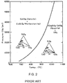
FIG. 2 is a pressure-temperature phase diagram showing the phases present in the reversible reaction 3CaCO3 + 2CaSiO3 ↔ 2Ca2SiO4·CaCO3 + CO2. -
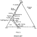
FIG. 3 is a phase diagram of the CaO-SiO2-CO2 system at a pressure of 1 kilobar. -
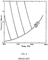
FIG. 4 is a pressure-temperature phase diagram showing the phases present in the reversible reaction MgO + CO2 ↔ MgCO3. -
FIG. 5 is a pressure-temperature phase diagram showing the equilibrium curves for the reversible reaction MgO + CO2 ↔ MgCO3 as a function of the proportion of CO2 in an inert gas. -
FIG. 6 is a temperature-composition phase diagram that illustrates the stability regions for various phases in the CaCO3-MgCO3 system. -
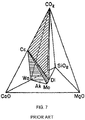
FIG. 7 is a tetrahedron diagram illustrating the phase relationships among the compounds CaO, MgO, SiO2 and CO2, and showing the CO2 deficient region below the Cc-Di-Wo and the Cc-Wo-Mo planes (shaded), where Cc denotes calcite, Wo denotes Wollastonite, Ak denotes Akermanite, Di denotes diopside, and Mo denotes monticellite (CaMgSiO4), -
FIG. 8 is a pressure-temperature phase diagram illustrating the phase relationships among the compounds CaO, MgO, SiO2 and CO2, with univariant curves emanating from the quaternary invariant point involving the phases calcite (Cc), diopside (Di), forsterite (Fo), monticellite (Mo), Akermanite (Ak), and CO2. The inset is the phase diagram for the three compound systems of CaCO3, MgO and SiO2. -
FIG. 9 is a schematic diagram of a CO2 composite material curing chamber that provides humidification according to principles of the invention. -
FIG. 10 is a schematic diagram of a curing chamber with multiple methods of humidity control as well as ability to control and replenish CO2 using constant flow or pressure regulation and that can control the temperature according to principles of the invention. -
FIGs. 11(a)-11(c) are schematic illustrations of cross-sections of bonding elements including three exemplary core morphologies: (a) fibrous, (b) elliptical, and (c) equiaxed. -
FIGs. 12(a)-12(f) are schematic illustrations of side view and cross section views of composite materials illustrating (a) 1D oriented fiber-shaped bonding elements in a dilute bonding matrix (bonding elements are not touching), (b) 2D oriented platelet shaped bonding elements in a dilute bonding matrix (bonding elements are not touching), (c) 3D oriented platelet shaped bonding elements in a dilute bonding matrix (bonding elements are not touching), and (d) randomly oriented platelet shaped bonding elements in a dilute bonding matrix (bonding elements are not touching), wherein the composite materials includes the bonding matrix and filler components such as polymers, metals, inorganic particles, aggregates etc., (e) a concentrated bonding matrix (with a volume fraction sufficient to establish a percolation network) of bonding elements where the matrix is 3D oriented, and (f) a concentrated bonding matrix (with a volume fraction sufficient to establish a percolation network) of randomly oriented bonding elements, wherein filler components such as polymers, metals, inorganic particles, aggregates etc. may be included. -
FIG. 13 shows an example of a cut aerated concrete sample (4 inches x 4 inches x 4 inches for demonstration purpose) made using synthetic wollastonite. - This invention provides a method for producing novel aerated composite materials and products manufactured therefrom that possess excellent physical and performance properties characteristic of aerated concretes but can be readily produced from widely available, low cost raw materials by a process suitable for large-scale production with improved energy consumption, reduced equipment need (e.g., without the need for autoclaves), and more desirable carbon footprint.
- The aerated composite materials produced by the method of the invention can be used either in load-bearing or non load-bearing applications. The homogeneous nature of their pore structure also imparts superior thermal and acoustic insulation properties compared to conventional aerated concretes. Additionally, the aerated composite materials of the invention can be readily prepared with large dimensions such as a large wall, floor, or roof panels and landscaping blocks.
- The aerated composite materials produced by the method of the invention exhibit excellent insulating qualities (both thermal and sound) as well as fire resistance. They can be produced at large-scales with much improved energy efficiency and more desirable carbon footprint than convention aerated concrete.
- The production of the aerated composite materials consumes CO2 resulting in CO2 net sequestration thereby making it carbon-neutral and exceptionally efficient from both financial and environmental conservation perspectives. In addition, the solid and homogeneous pore structures of these aerated composite materials create airtight building envelopes, minimizing uncontrolled air changes while helping maintain desired indoor temperatures while maximizing the efficiency of HVAC equipment. Additional benefits brought about by the unique aerated composite materials of the invention are reduction of material use, the ability to use recycled products, and avoidance of toxic emissions.
- The invention relates to a process for producing an article of an aerated composite material. The process includes: (1) forming a wet mixture, wherein the wet mixture comprises: water, a ground calcium silicate, filler particles, and an aerating agent; (2) casting the wet mixture in a mold; (3) allowing the aerating agent to generate a gaseous product thereby causing volume expansion of the wet mixture; (4) pre-curing the expanded mixture at a temperature in the range from 20°C to 80°C under an atmosphere of water and CO2 for a time sufficient to result in a pre-cured object suitable for achieving sufficient early-age strength required for de-molding and/or cutting; (5) de-molding and/or cutting the pre-cured object to desired dimensions; and (6) further curing the de-molded and/or cut pre-cured object at a temperature in the range from 20°C to 80°C for 5 hours to 40 hours under an atmosphere of water vapor and CO2 to yield the article. The ground calcium silicate has a specific particle size, d10 in the range from 0.25 µm to 5 µm, d50 in the range from 5 µm to 20 µm, and d90 in the range of 25 µm to 100 µm. The filler particles comprise calcium oxide or silica and have a particle size (d50) in the range from 0.25 µm to 200 µm. The ground calcium silicate includes one or more of synthetic wollastonite, pseudo-wollastonite, rankinite, gehlenite, belite, and alite.
- In certain embodiments, the wet mixture further includes: a set-controlling agent, a bubble stabilizing agent and a dispersing/viscosity-modifying agent. In certain embodiments, the wet mixture further includes an additive selected from dispersing, rheology modifying admixtures, pigments, retarders, and accelerators.
- In certain embodiments, forming a wet mixture includes mixing the following ingredients in the specified order of addition: adding a pre-determined portion of water; adding and mixing the set-controlling admixture; adding and mixing the dispersing/viscosity-modifying agent; adding and mixing ground calcium silicate; adding and mixing the filler particles to form a uniform slurry; and adding and mixing the aerating agent.
- In certain embodiments, the wet mixture comprises mixing the following ingredients in the specified percentages (wt% of the wet mixture): the ground calcium silicate in about 40 wt% to about 95 wt% (e.g., about 40 wt% to about 95 wt%, about 50 wt% to about 95 wt%, about 60 wt% to about 95 wt%, about 70 wt% to about 95 wt%, about 40 wt% to about 90 wt%, about 40 wt% to about 80 wt%, about 40 wt% to about 70 wt%, about 40 wt% to about 60 wt%), the filler particles in about 0 wt% to about 30 wt% (e.g., about 0 wt% to about 25 wt%, about 0 wt% to about 20 wt%, about 0 wt% to about 15 wt%, about 0 wt% to about 10 wt%, about 5 wt% to about 30 wt%, about 10 wt% to about 30 wt%, about 15 wt% to about 30 wt%, about 20 wt% to about 30 wt%), the set-controlling admixture in about 0 wt% to about 0.05 wt% (e.g., about 0 wt% to about 0.03 wt%, about 0 wt% to about 0.02 wt%, about 0.01 wt% to about 0.05 wt%, about 0.02 wt% to about 0.05 wt%, about 0.03 wt% to about 0.05 wt%), the dispersing/viscosity-modifying agent in about 0.05 wt% to about 0.25 wt% (e.g., about 0.05 wt% to about 0.20 wt%, about 0.05 wt% to about 0.15 wt%, about 0.05 wt% to about 0.10 wt%, about 0.10 wt% to about 0.25 wt%, about 0.15 wt% to about 0.25 wt%, about 0.20 wt% to about 0.25 wt%), and the aerating agent in about 0.05 wt% to about 0.30 wt% (e.g., about 0.05 wt% to about 0.25 wt%, about 0.05 wt% to about 0.20 wt%, about 0.05 wt% to about 0.15 wt%, about 0.05 wt% to about 0.10 wt%, about 0.15 wt% to about 0.30 wt%, about 0.20 wt% to about 0.30 wt%, about 0.25 wt% to about 0.30 wt%).
- In certain embodiments, the first portion of water accounts for about 60% to about 95% (e.g., about 60% to about 90%, about 60% to about 80%, about 60% to about 70%, about 70% to about 95%, about 80% to about 95%, about 90% to about 95%) of and the second portion of water accounts for about 5% to about 40% (e.g., about 5% to about 30%, about 5% to about 20%, about 5% to about 10%, about 10% to about 40%, about 15% to about 40%, about 20% to about 40%, about 30% to about 40%) of total water content in the wet mixture. In certain embodiments, the first portion of water accounts for about 90% of and the second portion of water accounts for about 10% of total water content in the wet mixture.
- Pre-curing the expanded mixture is performed under a pressure ranging from ambient atmospheric pressure to 206,843 N/m2 (30 psi) above ambient and under a CO2 concentration ranging from 25% to 99.5% (e.g., from about 50% to 99.5%, from about 60% to 99.5%, from about 70% to 99.5%, from about 80% to 99.5%, from about 90% to 99.5%, from 25% to about 99%, from 25% to about 90%, from 25% to about 80%, from about 50% to about 90%, from about 50% to about 80%, from about 50% to about 60%) to produce an aerated composite material.
- The pre-curing step is performed at a temperature in the range from 20°C to 80°C (e.g., from 20°C to about 70°C, from 20°C to about 60°C, from about 30°C to 80°C, from about 40°C to 80°C, from about 50°C to 80°C, from about 60°C to 80°C) for 1 hour to 10 hours (e.g., 1 hour to about 8 hours, 1 hour to about 6 hours, 1 hour to about 4 hours, about 2 hours to 10 hours, about 4 hours to 10 hours, about 6 hours to 10 hours) under a vapor comprising water and CO2. In certain embodiments, the pre-curing step is performed at a temperature of about 60°C for 1 hour to about 5 hours (e.g., about 2, 3, 4, 5 hours) under a vapor comprising water and CO2.
- Further curing the pre-cured object is performed at a temperature in the range from 20°C to 80°C (e.g., from 20°C to about 70°C, from 20°C to about 60°C, from about 30°C to 80°C, from about 40°C to 80°C, from about 50°C to 80°C, from about 60°C to 80°C) for 5 hours to 40 hours (e.g., 5 hours to about 30 hours, 5 hours to about 20 hours, 5 hours to about 15 hours, about 10 hours to 40 hours, about 15 hours to 40 hours, about 20 hours to 40 hours) under a vapor comprising water and CO2 and having a pressure in the range from ambient atmospheric pressure to 206,843 N/m2 (30 psi) above ambient atmospheric pressure (e.g., from ambient atmospheric pressure to about 20 psi above ambient atmospheric pressure, from ambient atmospheric pressure to about 10 psi above ambient atmospheric pressure, from about 10 psi above ambient atmospheric pressure to 206,843 N/m2 (30 psi) above ambient atmospheric pressure).
- In certain embodiments, further curing the pre-cured object is performed at a temperature in the range from about 30°C to about 70°C (e.g., from about 30°C to about 60°C, from about 30°C to about 50°C, from about 30°C to about 40°C, from about 40°C to about 70°C, from about 50°C to about 70°C, from about 60°C to about 70°C, from about 30°C to about 60°C) for about 10 hours to about 30 hours (e.g., about 10 hours to about 25 hours, about 10 hours to about 20 hours, about 10 hours to about 15 hours, about 15 hours to about 30 hours, about 20 hours to about 30 hours) under a vapor comprising water and CO2 and having a pressure in the range from ambient atmospheric pressure to 30 psi (206,843 N/m2) above ambient atmospheric pressure, ambient atmospheric pressure to about 20 psi above ambient atmospheric pressure).
- In certain embodiments, the pre-curing and further curing is carried out under a dynamic CO2 circulating flow condition.
- The relative humidity environment of the curing process may be adjusted to fit the desired outcome, for example, ranging from about 50% to about 98% (e.g., from about 60% to about 98%, from about 70% to about 98%, from about 80% to about 98%, from about 90% to about 98%, from about 50% to about 90%, from about 50% to about 80%, from about 50% to about 70%) to produce an aerated composite material exhibiting a uniform, homogeneous, and highly porous structure.
- In certain embodiments, the process further includes, after curing the pre-cured object, drying the cured object to remove residual water at a temperature in the range from about 20°C to about 110°C (e.g., from about 20°C to about 100°C, from about 20°C to about 90°C, from about 20°C to about 80°C, from about 20°C to about 70°C, from about 20°C to about 60°C, from about 30°C to about 110°C, from about 40°C to about 110°C, from about 50°C to about 110°C, from about 60°C to about 100°C) for about 12 hours to about 96 hours (e.g., about 12 hours to about 72 hours, about 12 hours to about 60 hours, about 12 hours to about 48 hours, about 12 hours to about 36 hours, about 12 hours to about 24 hours, about 24 hours to about 96 hours, about 36 hours to about 96 hours, about 36 hours to about 48 hours).
- In certain embodiments, the strength imparting components at the end of the curing process consist primarily of calcium carbonate (CaCO3 or calcite) along with amorphous calcium-silicate phases, and minor quantities of calcium-silicate hydrate (C-S-H) gel and calcium hydroxide (CH).
- Thus, various combinations of curing conditions may be devised to achieve the desired production process, including varied reaction temperatures, pressures and lengths of reaction.
- In certain embodiments, the ground calcium silicate is selected from wollastonite, pseudo-wollastonite, rankanite, belite, and alite.
- In certain embodiments, the ground calcium silicate or synthetic wollastonite consisting of ground wollastonite (CS) in an equivalent, 1:1, or 2:1 proportion, pseudo-wollastonite, rankinite (C3S2), gehlenite (C2AS), belite (C2S), and alite (C3S) where "C" refers to calcium oxide or lime, "S" refers to silicon dioxide or silica, "A" refers to aluminum oxide or alumina according to cement chemist notation (CCN) along with certain traces of impurities.
- The ground calcium silicate are characterized by d10 in the range from 0.25 µm to 5 µm (e.g., from 0.25 µm to about 4 µm, from 0.25 µm to about 3 µm, from 0.25 µm to about 2 µm, from 0.25 µm to about 1 µm, from about 0.5 µm to 5 µm, from about 1 µm to 5 µm, from about 2 µm to 5 µm), d50 in the range from 5 µm to 20 µm (e.g., from 5 µm to about 15 µm, from 5 µm to about 10 µm, from about 10 µm to 20 µm, from about 15 µm to 20 µm), and d90 in the range from 25 µm to 100 µm (e.g., 25 µm to about 80 µm, 25 µm to about 70 µm, 25 µm to about 60 µm, 25 µm to about 50 µm, about 40 µm to 100 µm, about 50 µm to 100 µm, about 60 µm to 100 µm, about 70 µm to 100 µm).
- Exemplary filler particles include lime, quartz (including sand), wollastonite, xonotlite, burned oil shale, fly - or volcanic-ash, stack dust from kilns, ground clay, pumice dust. Materials such as industrial waste materials (e.g., fly ash, slag, silica fume) may also be used as fillers. In certain preferred embodiments, light-weight aggregates such as perlite or vermiculite may also be used as fillers. In certain preferred embodiments, filler particles are made from a calcium oxide-rich material such as ground lime.
- As used herein, the term "lime" refers to naturally occurring or synthetic inorganic materials in which calcium oxide or calcium hydroxide predominate.
- As used herein, The term "quartz", as used herein, refers to any SiO2-based material, including common sands (construction and masonry), as well as glass and recycled glass. The term also includes any other recycled natural and synthetic materials that contain significant amounts of SiO2 (e.g., mica sometimes formulated as KAl2(AlSi3O10)).
- The filler particles comprise calcium oxide or silica and have a particle size (d50) in the range from 0.25 µm to 200 µm (e.g., from 0.25 µm to about 150 µm, from 0.25 µm to about 100 µm, from 0.25 µm to about 50 µm, from 0.25 µm to about 20 µm, from 0.25 µm to about 10 µm, from about 0.5 µm to 200 µm, from about 1 µm to 200 µm, from about 5 µm to 200 µm, from about 10 µm to 200 µm, from about 20 µm to 200 µm, from about 50 µm to 200 µm).
- In certain embodiments, the filler particles are selected from fly ash, bottom ash, slag having particle sizes ranging from about 0.5 µm to about 300 µm (e.g., from about 1 µm to about 300 µm, from about 5 µm to about 300 µm, from about 10 µm to about 300 µm, from about 50 µm to about 300 µm, from about 100 µm to about 300 µm, from about 0.5 µm to about 200 µm, from about 0.5 µm to about 100 µm, from about 0.5 µm to about 50 µm, from about 0.5 µm to about 20 µm, from about 0.5 µm to about 10 µm, from about 0.5 µm to about 5 µm).
- In certain embodiments, the filler particles are selected from limestone, miro-silica, and quartz having particle sizes ranging from about 1 µm to about 500 µm (e.g., from about 1 µm to about 400 µm, from about 1 µm to about 300 µm, from about 1 µm to about 200 µm, from about 1 µm to about 100 µm, from about 1 µm to about 50 µm, from about 1 µm to about 30 µm, from about 5 µm to about 500 µm, from about 10 µm to about 500 µm, from about 20 µm to about 500 µm, from about 50 µm to about 500 µm, from about 100 µm to about 500 µm, from about 200 µm to about 500 µm).
- In certain embodiments, the filler particles are selected from lightweight aggregates having particle sizes ranging from about 20 µm to about 500 µm (e.g., from about 20 µm to about 400 µm, from about 20 µm to about 300 µm, from about 20 µm to about 200 µm, from about 20 µm to about 100 µm, from about 50 µm to about 500 µm, from about 100 µm to about 500 µm, from about 200 µm to about 500 µm, from about 300 µm to about 500 µm).
- In certain embodiments, the set-controlling admixture is selected from a gluconate and sucrose. In certain embodiments, the dispersing/viscosity-modifying agent is a polycarboxilate based material.
- In exemplary embodiments, the ground calcium silicate is ground wollastonite, the filler particles comprises ground limestone, and silica, the activating-agent is ground lime, the set-controlling admixture is a gluconate, the viscosity-modifying agent is a polycarboxilate based material, and the aerating agent is aluminum paste.
- The plurality of voids serve to reduce the overall density of the aerated composite material while at the same time provide a three-dimensional porous network that facilitates uniform and expedited curing of the composite material. The plurality of voids may account for any suitable fraction of the overall volume of the aerated composite material dependent on the desired properties and applications at hand. For example, the plurality of voids may account for from about 50 vol.% to about 80 vol.% (e.g., from about 60 vol.% to about 80 vol.%, from about 65 vol.% to about 80 vol.%, about 60%, about 65%, about 70%, about 75%, about 80%) of the overall volume of the aerated composite material.
- The plurality of voids are caused by a gaseous material generated by an aerating agent. In certain preferred embodiments, the aerating agent includes a metal capable of reacting with acid to generate gaseous hydrogen. Exemplary aerating agents include: powder or paste of aluminum, powder of iron, powder of zinc, powder of calcium carbide, and hydrogen peroxide, or a mixture thereof. The aerating agents may have any suitable sizes, for example, ranging from about 10 µm to about 50 µm (e.g., from about 10 µm to 40 µm, from about 10 µm to 30 µm, from about 10 µm to 20 µm, from about 15 µm to 40 µm, from about 15 µm to 30 µm, from about 20 µm to 40 µm, larger than about 40 µm).
- Also disclosed herein (but not claimed) is an article of manufacture produced by a process according to the invention.
- The aerated composite material and/or the article of manufacture may be characterized by a density from about 300 kg/m3 to about 1500 kg/m3 (e.g., about 300 kg/m3 to 1200 kg/m3, about 300 kg/m3 to 1000 kg/m3, about 300 kg/m3 to 900 kg/m3, about 400 kg/m3 to 1200 kg/m3, about 400 kg/m3 to 1000 kg/m3, about 400 kg/m3 to 900 kg/m3, about 500 kg/m3 to 1200 kg/m3, about 500 kg/m3 to 1000 kg/m3).
- The aerated composite materials manufactured according to the process of the invention exhibit excellent compressive strength. For example, the aerated composite material and/or the article of manufacture may be characterized by a compressive strength from about 2.0 MPa to about 8.5 MPa (e.g., from about 2.0 MPa to about 6.0 MPa, from about 2.0 MPa to about 5.0 MPa, from about 3.0 MPa to about 8.5 MPa, from about 3.0 MPa to about 6.0 MPa, from about 3.0 MPa to about 5.0 MPa, from about 4.0 MPa to about 8.5 MPa).
- The aerated composite materials manufactured according to the process of the invention also exhibit excellent flexural strength. For example, the aerated composite material and/or the article of manufacture may be characterized by a flexural strength from about 0.4 MPa to about 1.7 MPa (e.g., from about 0.7 MPa to about 1.7 MPa, from about 1.0 MPa to about 1.7 MPa, from about 1.2 MPa to about 1.7 MPa, from about 1.0 MPa to about 1.5 MPa, from about 1.2 MPa to about 1.5 MPa).
- The aerated composite material exhibits a density from about 400 kg/m3 to 1200 kg/m3, a compressive strength from about 3.0 MPa to about 6.0 MPa, and a flexural strength from about 0.66 MPa to about 1.32 MPa. In certain embodiments, the aerated composite material exhibits a density from about 500 kg/m3 to 1000 kg/m3, a compressive strength from about 4.0 MPa to about 6.0 MPa, and a flexural strength from about 0.88 MPa to about 1.32 MPa.
- The aerated composite material may be prepared to exhibit a desired density and mechanical properties (e.g., meeting or exceeding the specifications of strength classes for Aerated Concrete according to ASTM C1693-11).
Table 1. ASTM Classifications Strength Class Compressive strength Nominal Dry Bulk Density Density Limits psi (MPa) kg/m3 kg/m3 minimum Lower limit Upper limit AAC-2 290 (2.0) 350 550 AAC-3 435 (3.0) 450 650 AAC-4 580 (4.0) 450 650 AAC-5 725 (5.0) 550 750 AAC-6 870 (6.0) 550 750 - Also disclosed herein (but not claimed) is an aerated composite material that includes: (1) a plurality of bonding elements characterized by a specific particle size, d10 in the range from about 0.25 µm to about 5 µm, d50 in the range from about 5 µm to about 20 µm, and d90 in the range of about 25 µm to about 100 µm; (2) a plurality of filler particles having particle sizes in the range from about 0.5 µm to about 500 µm; and (3) a plurality of voids. Each bonding element comprises: a core comprising primarily calcium silicate, a silica-rich first or inner layer, and a calcium carbonate-rich second or outer layer. The plurality of bonding elements and the plurality of filler particles together form one or more bonding matrices and the bonding elements and the filler particles are substantially evenly dispersed therein and bonded together. The plurality of voids are bubble-shaped and/or interconnected channels account for from about 50 vol.% to about 80 vol.% of the composite material. The aerated composite material exhibits a density from about 300 kg/m3 to 1500 kg/m3, a compressive strength from about 2.0 MPa to about 8.5 MPa, and a flexural strength from about 0.4 MPa to about 1.7 MPa.
- In certain embodiments, the plurality of bonding elements are chemically transformed from a precursor calcium silicate other than wollastonite by reacting it with CO2 via a controlled hydrothermal liquid phase sintering process. In certain embodiments, the plurality of bonding elements are chemically transformed from a precursor calcium silicate comprising one or more of aluminum, magnesium and iron.
- The aerated composite material may further include one or more additives to modify the appearance, physical or mechanical properties of the product. Exemplary additives include rheology modifying admixtures, pigments, retarders, and accelerators.
- A pigment may be evenly dispersed or substantially unevenly dispersed in the bonding matrices, depending on the desired composite material. The pigment may be any suitable pigment including, for example, oxides of various metals (e.g., black iron oxide, cobalt oxide and chromium oxide). The pigment may be of any color or colors, for example, selected from black, white, blue, gray, pink, green, red, yellow and brown. The pigment may be present in any suitable amount depending on the desired composite material, for example in an amount ranging from about 0.0% to about 10% by weight (e.g., about 0.0% to about 8%, about 0.0% to about 6%, about 0.0% to about 5%, about 0.0% to about 4%, about 0.0% to about 3%, about 0.0% to about 2%, about 0.0% to about 1%, about 0.0% to about 0.5%, about 0.0% to about 0.3%, about 0.0% to about 2%, about 0.0% to about 0.1%,).
- Aerated composite materials manufactured according to the process of the invention may be used to manufacture a wide range of products of various sizes and dimensions including, for example, standard blocks, cored blocks, cladding blocks, shaftwall and fire blocks, lintel blocks, tongue and groove blocks, wall panels, floor panels, roof panels, plates, sidings, frames, fences, decorative and landscaping products, parking stops, etc. The variety of products can be produced from widely available, low cost raw materials by a process that does not require autoclaves and is suitable for continuous, large-scale production. The production methods are much improved over conventional aerated concretes in terms of both economics and environmental impact.
- This invention provides apparatus (not claimed) and methods used to manufacture novel composite materials that are cured predominantly by a CO2 consumption reaction. The materials exhibit useful properties and can be readily produced from widely available, low cost precursor materials by a process suitable for large-scale production with minimal environmental impact. The precursor materials include inexpensive and abundant calcium silicate rich materials, fine particles and coarse particles. The calcium silicate rich materials may be comprised of ground Wollastonite. The fine and coarse particles may be comprised of ground limestone or other calcium carbonate based materials, ground quartz or other SiO2 based materials, sand and crushed rock. The fine and coarse particles may also be comprised of crushed minerals such as granite, mica and feldspar. Other process components include water and CO2. Various additives can be used to modify and fine-tune the physical appearance and/or mechanical properties of the resulting composite material, such as additives selected from one or more of pigments (e.g., black iron oxide, cobalt oxide and chromium oxide), colored glass and/or colored quartz. Additives regarding water usage reduction and changes in rheology can also be used.
- The composite materials can be produced, as disclosed herein, using the energy-efficient Hydrothermal Liquid Phase Sintering (HLPS) process to create bonding elements which hold together the various components of the composite material. The composite materials can be manufactured at low cost and with favorable environmental impact. For example in preferred embodiments of the invention, CO2 is used as a reactive species resulting in sequestration of CO2 and the creation of bonding elements in the produced composite materials with in a carbon footprint unmatched by any existing production technology. The HLPS process is thermodynamically driven by the free energy of the chemical reaction(s) and reduction of surface energy (area) caused by crystal growth. The kinetics of the HLPS process proceed at a reasonable rate at low temperature because a solution (aqueous or nonaqueous) is used to transport reactive species instead of using a high melting point fluid or high temperature solid-state medium.
- Discussions of various features of HLPS can be found in
U.S. Patent No. 8,114,367 , U.S. Pub. No.US 2009/0143211 (Appl. Serial No.12/271,566 US 2011/0104469 (Appl. Serial No.12/984,299 U.S. Pub. No. 2009/0142578 (Appl. Serial No.12/271,513 U.S. Pub. No. 2013/0122267 (Appl. Serial No.13/411,218 U.S. Pub. No. 2012/0312194 (Appl. Serial No.13/491,098 WO 2009/102360 (PCT/US2008/083606 ),WO 2011/053598 (PCT/US2010/054146 ),WO 2011/090967 (PCT/US2011/021623 ),U.S. Provisional Patent Application No. 61/708,423 filed October 1, 2012 U.S. Patent Application Nos. 14/045,758 ,14/045,519 14/045,766 14045540, all filed October 3, 2013 U.S. Patent Application Nos. 14/207,413 ,14/207,421, filed March 12, 2014 U.S. Patent Application Nos. 14/207,920 ,14/209,238, filed March 13, 2014 U.S. Patent Application Nos. 14/295,601 ,14/295,402, filed June 4, 2014 - As used herein, the term "calcium silicate" refers to naturally-occurring minerals or synthetic materials that are comprised of one or more of a group of calcium-silicon-containing compounds including CS (wollastonite or pseudowollastonite, and sometimes formulated CaSiO3 or CaO·SiO2), C3S2 (rankinite, and sometimes formulated as Ca3Si2O7 or 3CaO·2SiO2), C2S (belite, β-Ca2SiO4 or larnite, β-Ca2SiO4 or bredigite, α-Ca2SiO4 or γ-Ca2SiO4, and sometimes formulated as Ca2SiO4 or 2CaO·SiO2), a calcium silicate rich amorphous phase, each of which materials may include one or more other metal ions and oxides (e.g., aluminum, magnesium, iron or manganese oxides), or blends thereof, or may include an amount of magnesium silicate in naturally-occurring or synthetic form(s) ranging from trace amount (1%) to about 50% or more by weight.
FIG. 1 through FIG. 8 are phase diagrams that show various phase interrelationships among some of the materials described. - The calcium-silicon-containing compounds may also include both crystalline and amorphous calcium-silicate phases, which may also comprise of other iron, magnesia, potassium, sodium, and alumina based compounds.
- The term "quartz", as used herein, refers to any SiO2-based material, including common sands (construction and masonry), as well as glass and recycled glass. The term also includes any other recycled natural and synthetic materials that contain significant amounts of SiO2 (e.g., mica sometimes formulated as KAl2(AlSi3O10)(OH)2).
- The composite material is characterized by a compressive strength from about 90 MPa to about 175 MPa (e.g., about 90 MPa to about 150 MPa, about 90 MPa to about 140 MPa, about 90 MPa to about 130 MPa, about 90 MPa to about 120 MPa, about 90 MPa to about 110 MPa, about 100 MPa to about 175 MPa, about 120 MPa to about 175 MPa, about 130 MPa to about 175 MPa, about 140 MPa to about 175 MPa, about 150 MPa to about 175 MPa, about 160 MPa to about 175 MPa).
- The composite material is characterized by a flexural strength from about 5 MPa to about 30 MPa (e.g., about 5 MPa to about 25 MPa, about 5 MPa to about 20 MPa, about 5 MPa to about 15 MPa, about 5 MPa to about 10 MPa, about 10 MPa to about 30 MPa, about 20 MPa to about 30 MPa, about 25 MPa to about 30 MPa).
- The composite material is characterized by water absorption of less than about 10% (e.g., less than about 8%, 5%, 4%, 3%, 2%, or 1%).
- The composite material may display one or more of desired textures, patterns and physical properties, in particular those that are characteristic of natural stone. In certain preferred embodiments, the composite material exhibits a visual pattern similar to natural stone. Other characteristics include colors (e.g., black, white, blue, pink, grey (pale to dark), green, red, yellow, brown, cyan (bluish-green) or purple) and textures.
- In the embodiments described, industrial grade CO2 at about 99% purity is used, which is provided by a variety of different industrial gas companies, such as Praxair, Inc., Linde AG, Air Liquide, and others. This supply can be held in large pressurized holding tanks in the form of liquid carbon dioxide regulated at a temperature such that it maintains a vapor pressure of approximately 300 PSIG. This gas is then piped to a CO2 curing enclosure or chamber. In the simplest system, CO2 is flowed through the enclosure at a rate sufficient to displace the ambient air in the enclosure. In general, the purge time will depend on the size of the enclosure and the rate that CO2 gas is provided. In many systems, this process of purging the enclosure of air can be performed in times measured in minutes to get the CO2 concentration up to a reasonable level so that curing can be performed thereafter. In simple systems, CO2 gas is then fed into the system at a predefined rate so s to maintain a concentration of CO2 sufficient to drive the curing reaction.
- As an example, we now describe a method for sustaining carbon dioxide concentrations during the reaction that is well suited for keeping a highly consistent concentration, although it is a "closed loop" process which tends to be the most expensive technique. This method uses the measurement of CO2 concentration in the system directly, and employs a controller such as a PLC to control the CO2 concentration at a set point with an electronic/automated control valve. A measurement technique to measure CO2 directly such as NDIR should preferably be employed. In the NDIR measurement method, a gas sample stream is pulled from the system via a low flow pump. A chiller is used to drop moisture out of the gas stream before it is sampled by the NDIR instrument. Therefore the measurement provided by the analyzer is missing the water vapor component of the gas stream and needs be adjusted to account for the humidity that has been removed from the test sample. A measurement of the humidity in the system gas flow can be performed using a dry bulb-wet bulb psychrometric technique, using a dry bulb-wet bulb humidity measurement device or using a different type of moisture sensor. The true CO2 concentration can be calculated using the computer control system or PLC. Once the true CO2 concentration is known, the actuated proportioning control valve can add dry CO2 into the system when it has been consumed and has gone below the set point that is desired at that time. In various embodiments, the set point can vary with time, if necessary, based on experience in curing specific compositions, shape and sizes of composite material specimens.
-
FIG. 9 is a schematic diagram of a CO2 composite material curing chamber that provides humidification according to principles of the invention. InFIG. 9 , a water supply is provided and water vapor is added to the atmosphere that is circulating within the curing chamber. The water can be any convenient source of potable water. In some embodiments, ordinary tap water is used. In some embodiments, the water can be converted to vapor by flowing through a misting nozzle or an atomizing spray nozzle, an electric vapor generator, a gas fired vapor generator, or by being heated above the gas temperature in the chamber so as to cause evaporation from a liquid water supply an example being a drum reactor with an immersion heater. In yet another embodiment, the CO2 supply can be flowed into the systems after having been bubbled through a heated water supply in order to increase relative humidity of the incoming gas stream an example being a drum reactor configured for "flow through" or "open loop" processing. - Relative humidity is an important parameter in both traditional concrete curing as well as in CO2 composite material curing. In a traditional curing chamber a moist air atmosphere exists that is comprised of mostly nitrogen, oxygen, and water vapor. In these systems relative humidity is most often measured by a standard capacitive sensor technology. However, CO2 curing chambers have a gas atmosphere comprised predominately of carbon dioxide that is incompatible with some types of these sensors. Sensing technology such as dry-bulb wet-bulb techniques that utilize the psychrometric ratios for carbon dioxide and water vapor or dipole polarization water vapor measurement instruments or chilled mirror hygrometers or capacitive humidity sensors can be used in the CO2 composite material curing systems described herein.
- Depending on the type and geometry of the product being cured, the design of the chamber, and the packing efficiency of product in the chamber the humidity may need to be either decreased or increased and regulated to a specified set point. Set points may range anywhere from 1% to 99% relative humidity. Three different methods for humidity control may exist in CO2 composite material curing processes that could be combined into a single system. One method for humidification in one embodiment of a CO2 curing system is represented in
FIG. 9 . Another method allows one to remove moisture from the system to cure the composite material products with CO2. A simple method of reducing the relative humidity is by displacing the humid gas in the system with a dry gas, such as carbon dioxide. In still another embodiment, one can reduce relative humidity and therefore remove water vapor from the gas by a non-purging method, which in one preferred embodiment is a chilled heat exchanger that performs water extraction. -
FIG. 10 is a schematic diagram of a curing chamber with multiple methods of humidity control as well as ability to control and replenish CO2 using constant flow or pressure regulation and that can control the temperature according to principles of the invention. This system is an example of a system that can provide closed loop control or control using feedback, in which set values of operating parameters such as CO2 concentration, humidity, and temperature that are desired at specific times in the process cycle are provided, and measurements are taken to see whether the actual value of the parameter being controlled is the desired value. If deviation from the desired value is measured, corrective action is taken to bring the value of the parameter into agreement with the desired value. Such control systems can be expensive and complex, and may be useful with regard to high value products or products that require very precise process conditions. - In some embodiments, temperature is measured utilizing a sensor such as a thermocouple or an RTD. The measurement signal is directed back to a controller or computer that is able to regulate energy into the heat exchanger and thereby adjust the temperature of the entire system over time. The blower is an important component of the heating system as it is able to help transfer the heat energy to the gas which transfers to the products and the chamber itself which is an important part of controlled moisture of the samples. The method of heating can be electric or gas fired. Jacket heaters may be utilized to control the temperature of the CO2 that flows through a chamber in contact with the heating jacket, any convenient source of heat can be used. The means of external heating may include but are not limited to electric heating, hot water heating, or hot oil heating. For CO2 curing chambers indirect gas fired systems have been utilized thus far and direct fired gas burners have been avoided because they will pull air and products of combustion into the system, thereby diluting the CO2 and making control of the CO2 concentration problematic. Some smaller scale systems such as the Drum Reactors utilize electric jacket heaters to heat the entire surface of the chamber rather than a heating element within the chamber.
- Another control parameter is gas velocity across the material that is to be cured in the system. The gas velocity can be very dependent on process equipment variables including but not limited to chamber design, baffle design, fan size, fan speed/power, number of fans, temperature gradient within the system, rack design within the system, and sample geometry within the system. The simplest method to control the gas velocity within the chamber is by adjusting the blower speed (RPM's), typically done by utilization of a variable frequency drive to allow for control of the blower motor speed. The blower can be used to circulate gas at a desired velocity in the curing chamber. Gas velocity in the system is measured in the system via a variety of different techniques including but not limited to pitot tubes measurement and laser Doppler detection systems. The measurement signal for gas velocity can be sent back to a computer system or programmable logic controller and be utilized as a control parameter in the curing profile.
- We also describe one or more articles of manufacture made from a composite material.
- Any suitable precursor materials may be employed including, for example, calcium silicate composition particles formed from CS (wollastonite or pseudowollastonite, and sometimes formulated CaSiO3 or CaO·SiO2), C3S2 (Rankinite, and sometimes formulated as Ca3Si2O7 or 3CaO·2SiO2), C2S (belite , β-Ca2SiO4 or larnite, β-Ca2SiO4 or "bredigite, α-Ca2SiO4 or γ-Ca2SiO4, and sometimes formulated as Ca2SiO4 or 2CaO·SiO2), and a calcium silicate rich amorphous phase. It is believed that calcium cations are leached from the calcium silicate composition particles and transform the peripheral portion of the calcium silicate composition particle into calcium-deficient state. As the calcium cations continue to be leached from the peripheral portion of the particle, the structure of the peripheral portion eventually become unstable and breaks down, thereby transforming the calcium-deficient peripheral portion of the particle into a predominantly silica-rich first layer. Meanwhile, a predominantly calcium carbonate second layer precipitates from the water.
- More specifically, the first layer and second layer may be formed from the precursor particle according the following reactions (1-3) which can use water as a reaction medium, and not as a reagent (that is, the water is not consumed):
CaSiO3 (s) + CO2 (g) → CaCO3 (s) + SiO2 (s) (1)
Ca3Si2O7 (s) + 3CO2 (g) → 3CaCO3 (s) + 2SiO2 (s) (2)
Ca2SiO4 (s) + 2CO2 (g) → 2CaCO3 (s) + SiO2 (s) (3)
- For example, in a silicate mineral carbonation reaction such as with calcium silicate compositions, CO2 is introduced as a gas phase that dissolves into an infiltration fluid, such as water. The dissolution of CO2 forms acidic carbonic species (such as carbonic acid, H2CO3) that results in a decrease of pH in solution. The weakly acidic solution incongruently dissolves calcium species from the calcium silicate phases. Calcium may be leached from calcium containing amorphous phases through a similar mechanism. The released calcium cations and the dissociated carbonate species lead to the precipitation of insoluble carbonates. Silica-rich layers are thought to remain on the mineral particles as calcium depleted layers.
- Thus CO2 preferentially reacts with the calcium cations of the calcium silicate composition precursor core, thereby transforming the peripheral portion of the precursor core into a silica-rich first layer and a calcium carbonate-rich second layer. Also, the presence of the first and second layers on the core act as a barrier to further reaction between calcium silicate and carbon dioxide, resulting in the bonding element having the core, first layer and second layer.
- Preferably, gas-assisted HLPS processes utilize partially infiltrated pore space so as to enable gaseous diffusion to rapidly infiltrate the porous preform and saturate thin liquid interfacial solvent films in the pores with dissolved CO2. CO2-based species have low solubility in pure water (1.5 g/L at 25 °C, 1 atm.). Thus, a substantial quantity of CO2 must be continuously supplied to and distributed throughout the porous preform to enable significant carbonate conversion. Utilizing gas phase diffusion offers a huge (about 100-fold) increase in diffusion length over that of diffusing soluble CO2 an equivalent time in a liquid phase. ("Handbook of chemistry and physics", Editor: D. R. Lide, .) This partially infiltrated state enables the reaction to proceed to a high degree of carbonation in a fixed period of time.
- Liquid water in the pores speeds up the reaction rate because it provides a medium for ionization of both carbonic acid and calcium species. However, water levels need to be low enough such that CO2 gas can diffuse into the porous matrix prior to dissolution in the pore-bound water phase. Furthermore, the actively dissolving porous preform serves as a template for expansive reactive crystal growth. Thus, the bonding element and matrices can be formed with minimal distortion and residual stresses. This enables large and complex shapes to result, such as those needed for infrastructure and building materials, in addition to many other applications.
- The time required for curing of a composite material object is determined by the ability of water vapor and CO2 gas to diffuse throughout the object. In general, thicker objects take longer to cure than thinner objects. Similarly, objects with high density (and fewer open pore spaces) take longer to cure than objects with low density (and more open pore spaces). The following table provides examples of how the curing times may vary with respect to the smallest thickness (or wall thickness or section thickness) of the three dimensions and the bulk density of an object that is being manufactured.
Table 2. Examples of Curing Times and Smallest Thickness Composite Material Smallest Thickness (mm) Composite Material Bulk Density (g/cm3) Approximate Curing Time (h) 10 2.4 2 25 1.6 - 2.3 8 - 12 75 2.1 - 2.3 16 100 0.4 - 0.8 8 - 12 200 1.5 72 200 2.4 72 - As schematically illustrated in
FIGs. 11(a) - 11(c) , a bonding element includes a core (represented by the black inner portion), a first layer (represented by the white middle portion) and a second or encapsulating layer (represented by the outer portion). The first layer may include only one layer or multiple sub-layers and may completely or partially cover the core. The first layer may exist in a crystalline phase, an amorphous phase or a mixture thereof, and may be in a continuous phase or as discrete particles. The second layer may include only one layer or multiple sub-layers and may also completely or partially cover the first layer. The second layer may include a plurality of particles or may be of a continuous phase, with minimal discrete particles. - A bonding element may exhibit any size and any regular or irregular, solid or hollow morphology depending on the intended application. Exemplary morphologies include: cubes, cuboids, prisms, discs, pyramids, polyhedrons or multifaceted particles, cylinders, spheres, cones, rings, tubes, crescents, needles, fibers, filaments, flakes, spheres, sub-spheres, beads, grapes, granulars, oblongs, rods, ripples, etc.
- In general, as discussed in greater detail herein, a bonding element is produced from reactive precursor materials (e.g., precursor particles) through a transformation process. The precursor particles may have any size and shape as long as they meet the needs of the intended application. The transformation process generally leads to the corresponding bonding elements having similar sizes and shapes of the precursor particles.
- Within the bonding matrix, the bonding elements may be positioned, relative to each other, in any one of a number of orientations.
FIGs. 12(a) - 12(f) schematically illustrate an exemplary bonding matrix that includes fiber- or platelet- shaped bonding elements in different orientations possibly diluted by the incorporation of filler material, as represented by the spacing between the bonding elements.FIG. 12(a) , for example, illustrates a bonding matrix that includes fiber-shaped bonding elements aligned in a one-direction ("1-D") orientation (e.g., aligned with respect to the x direction).FIG. 12(b) illustrates a bonding matrix that includes platelet-shaped bonding elements aligned in a two-direction ("2-D") orientation (e.g., aligned with respect to the x and y directions).FIG. 12(c) illustrates a bonding matrix that includes platelet-shaped bonding elements aligned in a three-direction ("3-D") orientation (e.g., aligned with respect to the x, y and z directions).FIG. 12(d) illustrates a bonding matrix that includes platelet-shaped bonding elements in a random orientation, wherein the bonding elements are not aligned with respect to any particular direction.FIG. 12(e) illustrates a bonding matrix that includes a relatively high concentration of platelet-shaped bonding elements that are aligned in a 3-D orientation.FIG. 12(f) illustrates a bonding matrix that includes a relatively low concentration of platelet- shaped bonding elements that are situated in a random orientation (a percolation network). The composite material ofFIG. 12(f) achieves the percolation threshold because a large proportion of the bonding elements are touching one another such that a continuous network of contacts are formed from one end of the material to the other end. The percolation threshold is the critical concentration above which bonding elements show long-range connectivity with either an ordered, e.g.,FIG. 12(e) , or random orientation, e.g.,FIG. 12(f) , of bonding elements. Examples of connectivity patterns can be found in, for example, Newnham, et al., "Connectivity and piezoelectric-pyroelectric composites", Mat. Res. Bull. vol. 13, pp. 525-536, 1978). - The plurality of bonding elements may be chemically transformed from any suitable precursor materials, for example, from any suitable calcium silicate composition precursor. The precursor calcium silicate composition may also include one or more chemical elements of aluminum, magnesium and iron.
- The plurality of bonding elements may have any suitable median particle size and size distribution dependent on the desired composite material. In certain embodiments, the plurality of bonding elements have a median particle size in the range of about 1 µm to about 100 µm (e.g., about 1 µm to about 80 µm, about 1 µm to about 60 µm, about 1 µm to about 50 µm, about 1 µm to about 40 µm, about 1 µm to about 30 µm, about 1 µm to about 20 µm, about 1 µm to about 10 µm, about 5 µm to about 90 µm, about 5 µm to about 80 µm, about 5 µm to about 70 µm, about 5 µm to about 60 µm, about 5 µm to about 50 µm, about 5 µm to about 40 µm, about 10 µm to about 80 µm, about 10 µm to about 70 µm, about 10 µm to about 60 µm, about 10 µm to about 50 µm, about 10 µm to about 40 µm, about 10 µm to about 30 µm, about 10 µm to about 20 µm).
- In some instances a composite material includes: a plurality of bonding elements and a plurality of filler particles. Each bonding element includes: a core comprising primarily calcium silicate, a silica-rich first or inner layer, and a calcium carbonate-rich second or outer layer. The plurality of bonding elements and the plurality of filler particles together form one or more bonding matrices and the bonding elements and the filler particles are substantially evenly dispersed therein and bonded together, whereby the composite material exhibits one or more textures, patterns and physical properties.
- The filler particles are made from a calcium carbonate-rich material such as limestone (e.g., ground limestone). In certain materials, the filler particles are made from one or more of SiO2-based or silicate-based material such as quartz, mica, granite, and feldspar (e.g., ground quartz, ground mica, ground granite, ground feldspar).
- Filler particles may include natural, synthetic and recycled materials such as glass, recycled glass, coal slag, calcium carbonate-rich material and magnesium carbonate-rich material.
- The weight ratio of (bonding elements : filler particles) may be any suitable ratios dependent on the desired composite material, for example, in the range of about (10 to 50) : about (50 to 90).
- The composite materials may display various patterns, textures and other characteristics, such as visual patterns of various colors. In addition, the composite materials of the invention exhibit compressive strength, flexural strength and water absorption properties similar to conventional concrete or the corresponding natural materials.
- The composite may further include a pigment. The pigment may be evenly dispersed or substantially unevenly dispersed in the bonding matrices, depending on the desired composite material. The pigment may be any suitable pigment including, for example, oxides of various metals (e.g., iron oxide, cobalt oxide, chromium oxide) The pigment may be of any color or colors, for example, selected from black, white, blue, gray, pink, green, red, yellow and brown. The pigment may be present in any suitable amount depending on the desired composite material, for example in an amount ranging from about 0.0% to about 10% by weight (e.g., about 0.0% to about 8%, about 0.0% to about 6%, about 0.0% to about 5%, about 0.0% to about 4%, about 0.0% to about 3%, about 0.0% to about 2%, about 0.0% to about 1%, about 0.0% to about 0.5%, about 0.0% to about 0.3%, about 0.0% to about 2%, about 0.0% to about 0.1%,).
- Synthetic Wollastonite (SC-C2), Donghai Golden Resources Industries, Donghai, China; Calcium Oxide, Austin, TX (Capitol Brand); Aluminum Paste, Eckrat America Corporation, New Jersey; Glenium 7500, BASF, New Jersey, Filler Materials and Gluconate, Multiple sources.
Table 3. Mixture Proportions (13.56 kg batch size) Solid Components: 70.64% 9.356 kg Synthetic Wollastonite (SC-C2) 63.62% 8.630 kg Lime (Calcium Oxide) 5.17% 0.702 kg Gluconate 0.03% 0.005 kg Aluminum paste 0.14% 0.028 kg Liquid Components: 29.36% 4.210 kg Tap Water 29.23% 4.310 kg Glenium 7500 0.123% 0.016 kg -
- 1. Measure and load all of the liquid component into a laboratory scale mixer.
- 2. Add 0.016 kg of viscosity-modifying admixture (Glenium 7500) in the water and stir gently..
- 3. Measure and load 8.630 kg of the first solid component, which is Synthetic Wollastonite (SC-C2) into the wet mixture.
- 4. Measure and load 0.702 kg of the second solid component, which is lime (Calcium Oxide) into the mixer and mix the two components at approximately 40 RPM for a duration of five minutes or more until a uniform slurry is formed.
- 5. Measure and load the remaining 0.005 kg of gluconate into the slurry and continue mixing at the same rate for approximately two minutes.
- 6. Measure and load 0.028 kg of Aluminum paste (final solid component) into the slurry and continue mixing at a lower rpm rate (30 RPM) for about thirty seconds followed by another thirty seconds of mixing at a higher rpm rate (50 RPM). This creates a wet mixture.
-
- 1. Lubricate the inner surfaces of each mold(s) using WD-40 or grease to lower the friction between the wet mixture and inner surfaces of the molds as well as to avoid the possibility of the wet mixture sticking to the mold surfaces during de-molding.
- 2. Pour the wet mixture from the mixer into mold(s) to approximately half the height of the mold. In most cases, no external vibration is required; however, if the mold size is small, then a slight shake or disturbance is required to level the mix.
- 3. Transfer the mold with the wet mixture to a pre-curing chamber for reaction.
-
- 1. The sample is reacted in the pre-curing chamber, which is set at 60 °C and 0.3 psi of CO2 gas for 3 hours.
- 2. After 3 hours of curing, the sample is taken out of the pre-curing chamber, de-molded and placed inside a 7 ft diameter, 12 ft long, horizontal, curing chamber. The curing chamber was purged with CO2 gas for 12 minutes. The temperature of the curing chamber was then set to 60 °C and hot water at 70°C was circulated at the bottom of the curing chamber to keep the chamber saturated with water vapor. The specimen inside the curing chamber was then cured or reacted under these conditions for 20 hours leading to a creation of a hardened or cured ceramic body.
- 3. The cured specimen was then removed from the curing chamber. The specimen was then placed in a drying oven and set at 90°C to remove any residual water. The extent of the reaction was calculated based on the weight gain during the reaction. For the samples prepared using the mixture proportions mentioned in Table 3, the extent of reaction was approximately 40% to approximately 60% assuming a complete reaction of aluminum with the binder and lime.
- Photograph:
FIG. 13 shows an example of a cut aerated concrete sample (4 inches x 4 inches x 4 inches for demonstration purpose) made using synthetic wollastonite. - From the preliminary trials and formulation studies, aerated concretes have been produced using the raw materials and processes mentioned previously having a minimum density of about 525 to 725 kg/m3 for a corresponding compressive strength of up to 4 MPa. Also, compressive strengths of up to 5.0 MPa have been demonstrated for a density of approximately 850 kg/m3. Although these densities and compressive strengths are typical for aerated concretes, the grouping of these materials based on a particular strength class is restricted. The reaction conditions can be further optimized to achieve improved mechanical and performance characteristics.
- The dimensions of the samples used to carry out several trials for the assessment of material performance are 2-inch and 4-inch cubes, along with 4-in by 4-in by 14-in prismatic specimens.
- In this specification and the appended claims, the singular forms "a," "an," and "the" include plural reference, unless the context clearly dictates otherwise.
- Unless defined otherwise, all technical and scientific terms used herein have the same meaning as commonly understood by one of ordinary skill in the art. Although any methods and materials similar or equivalent to those described herein can also be used in the practice or testing of the present disclosure, the preferred methods and materials are now described. Methods recited herein may be carried out in any order that is logically possible, in addition to a particular order disclosed.
- The representative examples disclosed herein are intended to help illustrate the invention, and are not intended to, nor should they be construed to, limit the scope of the invention. Indeed, various modifications of the invention and many further embodiments thereof, in addition to those shown and described herein, will become apparent to those skilled in the art from the full contents of this document, including the examples which follow and the references to the scientific and patent literature cited herein. The following examples contain important additional information, exemplification and guidance that can be adapted to the practice of this invention in its various embodiments and equivalents thereof.
Claims (8)
- A process for producing an article of an aerated composite material, comprising:forming a wet mixture, wherein the wet mixture comprises:water,a ground calcium silicate, comprising one or more of synthetic wollastonite, pseudo-wollastonite, rankinite, gehlenite, belite, and alite, having a specific particle size, d10 in the range from 0.25 µm to 5 µm, d50 in the range from 5 µm to 20 µm, and d90 in the range of 25 µm to 100 µm,filler particles comprising calcium oxide or silica having a particle size (dso) in the range from 0.25 µm to 200 µm, andan aerating agent,casting the wet mixture in a mold;allowing the aerating agent to generate a gaseous product thereby causing volume expansion of the wet mixture;pre-curing the expanded mixture under a pressure ranging from ambient atmospheric pressure to 206,843 N/m2 (30 psi) at a temperature in the range from 20°C to 80°C, under an atmosphere of water and CO2, under a CO2 concentration ranging from 25% to 99.5%, and for 1 hour to 10 hours;de-molding and/or cutting the pre-cured object to desired dimensions; andfurther curing the de-molded and/or cut pre-cured object under a pressure ranging from ambient atmospheric pressure to 206,843 N/m2 (30 psi) above ambient, at a temperature in the range from 20°C to 80°C for 5 hours to 40 hours under an atmosphere of water vapor and CO2, under a relative humidity ranging from 50 to 98%, to yield the article.
- The process of Claim 1, wherein the wet mixture further comprises:a set-controlling agent;a bubble stabilizing agent, anda dispersing/viscosity-modifying agent.
- The process of Claim 1 or 2, further comprising after curing the pre-cured object,
drying the cured object to remove residual water at a temperature in the range from 20°C to 110°C for 12 hours to 96 hours. - The process of any of Claims 1-3, wherein the pre-curing and further curing is carried out under a dynamic CO2 circulating flow condition.
- The process of any of Claims 2-4, wherein forming a wet mixture comprises mixing the following ingredients in the specified order of addition:adding a pre-determined portion of water;adding and mixing the set-controlling admixture;adding and mixing the dispersing/viscosity-modifying agent;adding and mixing ground calcium silicate;adding and mixing the filler particles to form a uniform slurry; andadding and mixing the aerating agent, orthe wet mixture comprises mixing the following ingredients in the specified percentages:the ground calcium silicate in 40 to 95 wt% of the wet mixture,the filler particles in 0 to 30 wt% of the wet mixture,the set-controlling admixture in 0 to 0.05 wt% of the wet mixture,the dispersing/viscosity-modifying agent in 0.05 to 0.25 wt% of the wet mixture, andthe aerating agent in 0.05 to 0.30 wt% of the wet mixture.
- The process of any of Claims 1-5, wherein the ground calcium silicate is selected from wollastonite, pseudo-wollastonite, rankanite, belite, and alite.
- The process of any of Claims 1-6, wherein the aerating agent is selected from aluminum, iron, zinc, in powder and or paste form or hydrogen peroxide in liquid form.
- The process of any of Claims 2-7, wherein the set-controlling admixture is selected from a gluconate and sucrose, and/or the dispersing/viscosity-modifying agent is a polycarboxilate based material, and/or, wherein at the end of the curing step strength imparting components consist primarily of calcium carbonate and amorphous calcium-silicate phases, and calcium-silicate hydrate gel and calcium hydroxide.
Applications Claiming Priority (2)
| Application Number | Priority Date | Filing Date | Title |
|---|---|---|---|
| US201361868155P | 2013-08-21 | 2013-08-21 | |
| PCT/US2014/051811 WO2015026900A2 (en) | 2013-08-21 | 2014-08-20 | Aerated composite materials, methods of production and uses thereof |
Publications (3)
| Publication Number | Publication Date |
|---|---|
| EP3099459A2 EP3099459A2 (en) | 2016-12-07 |
| EP3099459A4 EP3099459A4 (en) | 2017-11-29 |
| EP3099459B1 true EP3099459B1 (en) | 2020-04-01 |
Family
ID=52480635
Family Applications (1)
| Application Number | Title | Priority Date | Filing Date |
|---|---|---|---|
| EP14837664.3A Active EP3099459B1 (en) | 2013-08-21 | 2014-08-20 | Methods of production of aerated composite materials |
Country Status (9)
| Country | Link |
|---|---|
| US (2) | US9963392B2 (en) |
| EP (1) | EP3099459B1 (en) |
| JP (1) | JP6479805B2 (en) |
| CN (1) | CN106457604B (en) |
| BR (1) | BR112016003767B1 (en) |
| CA (1) | CA2921642C (en) |
| EA (1) | EA037008B1 (en) |
| TW (1) | TW201516017A (en) |
| WO (1) | WO2015026900A2 (en) |
Families Citing this family (37)
| Publication number | Priority date | Publication date | Assignee | Title |
|---|---|---|---|---|
| EA037008B1 (en) * | 2013-08-21 | 2021-01-26 | Солидия Текнолоджиз, Инк. | AERATED COMPOSITE MATERIALS, METHODS FOR THEIR PRODUCTION AND APPLICATION |
| JP6957346B2 (en) | 2014-08-04 | 2021-11-02 | ソリディア テクノロジーズ インコーポレイテッドSolidia Technologies, Inc. | Calcium silicate composition capable of chlorination and its production method |
| WO2016054602A1 (en) | 2014-10-03 | 2016-04-07 | Solidia Technologies, Inc. | Composition carbonatable calcium silicate cement containing hydrating materials |
| MX374825B (en) | 2015-03-20 | 2025-03-06 | Solidia Technologies Inc | MICROSTRUCTURABLE CALCIUM CARBONATE SILICATE CLINKER AND METHODS THEREOF. |
| CN104876462B (en) * | 2015-05-14 | 2016-10-26 | 南京工业大学 | Cementing material capable of absorbing CO 2 and preparation method thereof |
| US10695949B2 (en) * | 2015-05-18 | 2020-06-30 | Solidia Technologies, Ltd. | Lightweight composite materials produced from carbonatable calcium silicate and methods thereof |
| EP4230584A3 (en) * | 2016-01-19 | 2023-12-13 | Solidia Technologies, Inc. | Novel cement chemistries |
| JP2019507098A (en) | 2016-03-04 | 2019-03-14 | ソリディア テクノロジーズ インコーポレイテッドSolidia Technologies, Inc. | Calcium silicate cement capable of white carbonation, and production method and use thereof |
| US10556834B2 (en) | 2016-03-11 | 2020-02-11 | Solidia Technologies, Inc. | Hazing control for carbonatable calcium silicate-based cements and concretes |
| EA037910B1 (en) | 2016-05-31 | 2021-06-04 | Солидия Текнолоджиз, Инк. | CONDITIONED CURING SYSTEMS AND CURING METHODS |
| CN108241721B (en) * | 2016-12-27 | 2020-07-31 | 北京国双科技有限公司 | Keyword-based article sorting method and device |
| EP3577088B1 (en) * | 2017-02-01 | 2021-05-19 | Omya International AG | Improved inorganic pigment-containing cement-based product and method for its preparation |
| EA201991989A1 (en) * | 2017-03-23 | 2020-05-18 | Солидия Текнолоджиз, Инк. | CARBONIZABLE CEMENTS AND CONCRETES BASED ON CALCIUM SILICATE, CONTAINING MINERAL ADDITIVES AND THEIR METHODS |
| CA3056943A1 (en) * | 2017-03-23 | 2018-09-27 | Solidia Technologies, Inc. | Mineral additives and production of lightweight composite materials from carbonatable calcium silicate |
| EP3713895B1 (en) | 2017-11-21 | 2025-10-22 | Solidia Technologies, Inc. | Carbonatable calcium silicate-based compositions and concretes for improving the strength development |
| WO2019101809A1 (en) | 2017-11-21 | 2019-05-31 | Holcim Technology Ltd | Compositions and method to improve the aesthetics of calcium silicate-based cements and concretes |
| EP3713896A1 (en) | 2017-11-21 | 2020-09-30 | Solidia Technologies, Inc. | Compositions and method to improve the durability of calcium silicate-based cements and concretes |
| WO2019112555A1 (en) * | 2017-12-04 | 2019-06-13 | Solidia Technologies, Inc. | Composite materials, methods of production and uses thereof |
| CN108340480B (en) * | 2018-01-24 | 2019-07-09 | 浙江大学 | A method of utilizing carbon dioxide step mineralising curing concrete building block |
| WO2020206011A1 (en) | 2019-04-02 | 2020-10-08 | Oxy Low Carbon Ventures, Llc | Methods involving cements that employ carbon dioxide as a reactant |
| WO2021067920A1 (en) * | 2019-10-04 | 2021-04-08 | Premier Magnesia, Llc | Geopolymer cement |
| CN111056811A (en) * | 2019-12-23 | 2020-04-24 | 解正祥 | Preparation method of aerated concrete block |
| US11426708B2 (en) | 2020-03-02 | 2022-08-30 | King Abdullah University Of Science And Technology | Potassium-promoted red mud as a catalyst for forming hydrocarbons from carbon dioxide |
| US11420915B2 (en) | 2020-06-11 | 2022-08-23 | Saudi Arabian Oil Company | Red mud as a catalyst for the isomerization of olefins |
| US11495814B2 (en) | 2020-06-17 | 2022-11-08 | Saudi Arabian Oil Company | Utilizing black powder for electrolytes for flow batteries |
| US12000056B2 (en) | 2020-06-18 | 2024-06-04 | Saudi Arabian Oil Company | Tandem electrolysis cell |
| EP3939945B1 (en) * | 2020-07-13 | 2026-05-20 | Oliment ® Gmbh | METHOD FOR PRODUCEING A BUILDING MATERIAL |
| US11820658B2 (en) | 2021-01-04 | 2023-11-21 | Saudi Arabian Oil Company | Black powder catalyst for hydrogen production via autothermal reforming |
| US11427519B2 (en) | 2021-01-04 | 2022-08-30 | Saudi Arabian Oil Company | Acid modified red mud as a catalyst for olefin isomerization |
| US11718522B2 (en) | 2021-01-04 | 2023-08-08 | Saudi Arabian Oil Company | Black powder catalyst for hydrogen production via bi-reforming |
| US11814289B2 (en) | 2021-01-04 | 2023-11-14 | Saudi Arabian Oil Company | Black powder catalyst for hydrogen production via steam reforming |
| US11724943B2 (en) | 2021-01-04 | 2023-08-15 | Saudi Arabian Oil Company | Black powder catalyst for hydrogen production via dry reforming |
| RU2769184C1 (en) * | 2021-06-16 | 2022-03-29 | Федеральное государственное бюджетное образовательное учреждение высшего образования "Тверской государственный технический университет" | Expanded claydit block |
| US12018392B2 (en) | 2022-01-03 | 2024-06-25 | Saudi Arabian Oil Company | Methods for producing syngas from H2S and CO2 in an electrochemical cell |
| CN116120017A (en) * | 2023-02-24 | 2023-05-16 | 扬州华运新材料科技有限公司 | Preparation process of renewable lightweight concrete |
| WO2025164672A1 (en) * | 2024-02-02 | 2025-08-07 | 旭化成ホームズ株式会社 | Aerated composite material |
| WO2025164682A1 (en) * | 2024-02-02 | 2025-08-07 | 旭化成ホームズ株式会社 | Aerated composite material |
Family Cites Families (41)
| Publication number | Priority date | Publication date | Assignee | Title |
|---|---|---|---|---|
| JPS57183344A (en) * | 1981-05-01 | 1982-11-11 | Asahi Chemical Ind | Manufacture of lightweight foamed concrete |
| US4436498A (en) | 1982-02-01 | 1984-03-13 | Conger/Murray Systems, Inc. | Apparatus for curing concrete products |
| SU1329972A1 (en) * | 1985-10-03 | 1987-08-15 | Институт механики металлополимерных систем АН БССР | Method of producing composite material based on phenolformaldehyde binder and wooden filler |
| US4956321A (en) | 1988-06-16 | 1990-09-11 | Armstrong World Industries, Inc. | Surface pacified wollastonite |
| AU8101491A (en) * | 1990-06-29 | 1992-01-23 | Gui Gerard De Jager | A process for manufacturing reinforced composites and filament material for use in said process |
| KR960700869A (en) * | 1993-03-08 | 1996-02-24 | 에쌈 카소기 | INSULATION BARRIERS HAVING A HYDRAULICALLY SETTABLE MATRIX |
| JP3618001B2 (en) * | 1993-12-13 | 2005-02-09 | 大同コンクリート工業株式会社 | Porous open cell concrete molded body and method for producing the same composite |
| JP2001261461A (en) * | 2000-03-16 | 2001-09-26 | Clion Co Ltd | Production process of lightweight cellular concrete |
| JP3735233B2 (en) * | 2000-04-19 | 2006-01-18 | 積水化学工業株式会社 | Method for producing inorganic carbonized cured body |
| US6773500B1 (en) * | 2000-05-31 | 2004-08-10 | Isg Resources, Inc. | Fiber reinforced aerated concrete and methods of making same |
| US7041167B2 (en) * | 2001-03-05 | 2006-05-09 | James Hardie International Finance B.V. | Low density accelerant and strength enhancing additive for cementitious products and methods of using same |
| US20050284339A1 (en) | 2001-04-03 | 2005-12-29 | Greg Brunton | Durable building article and method of making same |
| US7208112B2 (en) * | 2002-01-04 | 2007-04-24 | Anchor Wall Systems, Inc. | Concrete block and method of making same |
| JP2005281087A (en) * | 2004-03-30 | 2005-10-13 | Clion Co Ltd | Method for producing building material |
| US8815328B2 (en) | 2005-01-04 | 2014-08-26 | Rutgers, The State University Of New Jersey | Hydroxyapatite with controllable size and morphology |
| JP2006213559A (en) * | 2005-02-02 | 2006-08-17 | Sekisui Chem Co Ltd | Manufacturing method of inorganic carbonate cured body |
| US20070062416A1 (en) | 2005-09-22 | 2007-03-22 | Brzuskiewicz John E | Patching composition having tailorable appearance properties |
| CA2687940A1 (en) * | 2007-05-29 | 2008-12-04 | Microban Products Company | Antimicrobial cementitious composition, method and article |
| WO2009065031A1 (en) | 2007-11-15 | 2009-05-22 | Rutgers, The State University Of New Jersey | Systems and methods for capture and sequestration of gases and compositions derived therefrom |
| AU2008350276B2 (en) | 2007-11-15 | 2014-05-08 | Rutgers, The State University Of New Jersey | Method of hydrothermal liquid phase sintering of ceramic materials and products derived therefrom |
| US20090133361A1 (en) | 2007-11-27 | 2009-05-28 | Southern Cross Building Products, Llc | High-performance environmentally friendly building panel and related manufacturing methods |
| FR2925042B1 (en) | 2007-12-14 | 2010-10-22 | Lafarge Platres | ADJUVANT FOR HYDRAULIC BINDER |
| TW201026597A (en) | 2008-09-30 | 2010-07-16 | Calera Corp | CO2-sequestering formed building materials |
| JP5588142B2 (en) * | 2009-10-05 | 2014-09-10 | 旭化成建材株式会社 | Lightweight cellular concrete |
| US8114214B2 (en) | 2009-12-31 | 2012-02-14 | Calera Corporation | Methods and compositions using calcium carbonate |
| US20110158873A1 (en) | 2010-01-22 | 2011-06-30 | Rutgers, The State University Of New Jersey | Sequestration of a gas emitted by an industrial plant |
| CN101823864B (en) * | 2010-04-14 | 2013-01-23 | 吴智深 | Manufacturing method of aerated concrete |
| UA113844C2 (en) | 2011-03-05 | 2017-03-27 | THE BINDING ELEMENT, THE BINDING MATRIX AND THE COMPOSITION MATERIAL HAVING THE BINDING ELEMENT AND THE METHOD OF MANUFACTURING THEREOF | |
| US9216926B2 (en) | 2011-06-09 | 2015-12-22 | Rutgers, The State University Of New Jersey | Synthetic formulations and methods of manufacturing and using thereof |
| US20140342124A1 (en) | 2012-10-04 | 2014-11-20 | Dawid Zambrzycki | Wood-like composite materials and methods of preparation thereof |
| US20140127458A1 (en) | 2012-10-04 | 2014-05-08 | Dawid Zambrzycki | Slate-like composite materials and methods of preparation thereof |
| US20140127450A1 (en) | 2012-10-04 | 2014-05-08 | Richard E. Riman | Marble-like composite materials and methods of preparation thereof |
| CN105555734A (en) | 2013-03-13 | 2016-05-04 | 索里迪亚科技公司 | Pavers and block composite materials and methods of preparation thereof |
| EA031855B1 (en) | 2013-03-13 | 2019-03-29 | Солидия Текнолоджиз, Инк. | Composite railroad tie and method of production thereof |
| EA201591671A1 (en) | 2013-03-13 | 2016-07-29 | Солидия Текнолоджиз, Инк. | AERED COMPOSITION MATERIALS, METHODS OF THEIR RECEIVING AND APPLICATION |
| EA032774B1 (en) | 2013-03-14 | 2019-07-31 | Солидия Текнолоджиз, Инк. | CURING SYSTEMS FOR MATERIALS ABSORBING CARBON DIOXIDE |
| WO2014197545A1 (en) | 2013-06-07 | 2014-12-11 | Solidia Technologies, Inc. | Pervious composite materials, methods of production and uses thereof |
| HUE059188T2 (en) | 2013-06-07 | 2022-10-28 | Solidia Technologies Inc | Process for the production of composite material flat buga |
| EA037008B1 (en) * | 2013-08-21 | 2021-01-26 | Солидия Текнолоджиз, Инк. | AERATED COMPOSITE MATERIALS, METHODS FOR THEIR PRODUCTION AND APPLICATION |
| US9878951B2 (en) * | 2013-10-04 | 2018-01-30 | Solidia Technologies, Inc. | Hollow-core articles and composite materials, methods of production and uses thereof |
| US10695949B2 (en) * | 2015-05-18 | 2020-06-30 | Solidia Technologies, Ltd. | Lightweight composite materials produced from carbonatable calcium silicate and methods thereof |
-
2014
- 2014-08-20 EA EA201690405A patent/EA037008B1/en not_active IP Right Cessation
- 2014-08-20 JP JP2016536402A patent/JP6479805B2/en not_active Expired - Fee Related
- 2014-08-20 WO PCT/US2014/051811 patent/WO2015026900A2/en not_active Ceased
- 2014-08-20 CA CA2921642A patent/CA2921642C/en active Active
- 2014-08-20 EP EP14837664.3A patent/EP3099459B1/en active Active
- 2014-08-20 CN CN201480057988.3A patent/CN106457604B/en not_active Expired - Fee Related
- 2014-08-20 US US14/463,901 patent/US9963392B2/en active Active
- 2014-08-20 BR BR112016003767-7A patent/BR112016003767B1/en active IP Right Grant
- 2014-08-21 TW TW103128842A patent/TW201516017A/en unknown
-
2018
- 2018-05-07 US US15/972,760 patent/US10787390B2/en active Active
Non-Patent Citations (1)
| Title |
|---|
| None * |
Also Published As
| Publication number | Publication date |
|---|---|
| US9963392B2 (en) | 2018-05-08 |
| US20190039955A1 (en) | 2019-02-07 |
| EP3099459A4 (en) | 2017-11-29 |
| JP6479805B2 (en) | 2019-03-06 |
| JP2016531077A (en) | 2016-10-06 |
| EA201690405A1 (en) | 2016-12-30 |
| BR112016003767A2 (en) | 2017-08-01 |
| WO2015026900A2 (en) | 2015-02-26 |
| CA2921642A1 (en) | 2015-02-26 |
| EA037008B1 (en) | 2021-01-26 |
| CA2921642C (en) | 2021-08-03 |
| US10787390B2 (en) | 2020-09-29 |
| BR112016003767B1 (en) | 2022-06-28 |
| CN106457604B (en) | 2023-07-11 |
| CN106457604A (en) | 2017-02-22 |
| WO2015026900A3 (en) | 2016-11-03 |
| TW201516017A (en) | 2015-05-01 |
| EP3099459A2 (en) | 2016-12-07 |
| US20150056437A1 (en) | 2015-02-26 |
Similar Documents
| Publication | Publication Date | Title |
|---|---|---|
| US10787390B2 (en) | Aerated composite materials, methods of production and uses thereof | |
| US10315335B2 (en) | Rapid curing of thin composite material sections | |
| EP3405446B1 (en) | Novel cement chemistries | |
| EP3052454B1 (en) | Hollow core slabs and method of production thereof | |
| JP2023159143A (en) | Composite materials, manufacturing methods and their use | |
| EP3004019B1 (en) | Production of pervious composite materials | |
| EP3271309A1 (en) | Composite materials and bonding elements from carbonation of calcium silicate and methods thereof | |
| US10815154B2 (en) | Composite materials, methods of production and uses thereof |
Legal Events
| Date | Code | Title | Description |
|---|---|---|---|
| PUAI | Public reference made under article 153(3) epc to a published international application that has entered the european phase |
Free format text: ORIGINAL CODE: 0009012 |
|
| STAA | Information on the status of an ep patent application or granted ep patent |
Free format text: STATUS: REQUEST FOR EXAMINATION WAS MADE |
|
| 17P | Request for examination filed |
Effective date: 20160317 |
|
| AK | Designated contracting states |
Kind code of ref document: A2 Designated state(s): AL AT BE BG CH CY CZ DE DK EE ES FI FR GB GR HR HU IE IS IT LI LT LU LV MC MK MT NL NO PL PT RO RS SE SI SK SM TR |
|
| A4 | Supplementary search report drawn up and despatched |
Effective date: 20171102 |
|
| RIC1 | Information provided on ipc code assigned before grant |
Ipc: C04B 40/00 20060101ALI20171025BHEP Ipc: E04C 1/00 20060101ALI20171025BHEP Ipc: B28B 5/00 20060101ALI20171025BHEP Ipc: B28B 1/50 20060101AFI20171025BHEP Ipc: C04B 38/02 20060101ALI20171025BHEP Ipc: B28B 11/14 20060101ALI20171025BHEP Ipc: B28B 11/24 20060101ALI20171025BHEP Ipc: C04B 20/00 20060101ALI20171025BHEP |
|
| STAA | Information on the status of an ep patent application or granted ep patent |
Free format text: STATUS: EXAMINATION IS IN PROGRESS |
|
| 17Q | First examination report despatched |
Effective date: 20190529 |
|
| GRAP | Despatch of communication of intention to grant a patent |
Free format text: ORIGINAL CODE: EPIDOSNIGR1 |
|
| STAA | Information on the status of an ep patent application or granted ep patent |
Free format text: STATUS: GRANT OF PATENT IS INTENDED |
|
| INTG | Intention to grant announced |
Effective date: 20191115 |
|
| GRAS | Grant fee paid |
Free format text: ORIGINAL CODE: EPIDOSNIGR3 |
|
| GRAA | (expected) grant |
Free format text: ORIGINAL CODE: 0009210 |
|
| STAA | Information on the status of an ep patent application or granted ep patent |
Free format text: STATUS: THE PATENT HAS BEEN GRANTED |
|
| AK | Designated contracting states |
Kind code of ref document: B1 Designated state(s): AL AT BE BG CH CY CZ DE DK EE ES FI FR GB GR HR HU IE IS IT LI LT LU LV MC MK MT NL NO PL PT RO RS SE SI SK SM TR |
|
| REG | Reference to a national code |
Ref country code: GB Ref legal event code: FG4D |
|
| REG | Reference to a national code |
Ref country code: CH Ref legal event code: EP Ref country code: AT Ref legal event code: REF Ref document number: 1250797 Country of ref document: AT Kind code of ref document: T Effective date: 20200415 |
|
| REG | Reference to a national code |
Ref country code: DE Ref legal event code: R096 Ref document number: 602014063274 Country of ref document: DE |
|
| REG | Reference to a national code |
Ref country code: IE Ref legal event code: FG4D |
|
| PG25 | Lapsed in a contracting state [announced via postgrant information from national office to epo] |
Ref country code: BG Free format text: LAPSE BECAUSE OF FAILURE TO SUBMIT A TRANSLATION OF THE DESCRIPTION OR TO PAY THE FEE WITHIN THE PRESCRIBED TIME-LIMIT Effective date: 20200701 |
|
| REG | Reference to a national code |
Ref country code: NL Ref legal event code: MP Effective date: 20200401 |
|
| REG | Reference to a national code |
Ref country code: LT Ref legal event code: MG4D |
|
| PG25 | Lapsed in a contracting state [announced via postgrant information from national office to epo] |
Ref country code: PT Free format text: LAPSE BECAUSE OF FAILURE TO SUBMIT A TRANSLATION OF THE DESCRIPTION OR TO PAY THE FEE WITHIN THE PRESCRIBED TIME-LIMIT Effective date: 20200817 Ref country code: LT Free format text: LAPSE BECAUSE OF FAILURE TO SUBMIT A TRANSLATION OF THE DESCRIPTION OR TO PAY THE FEE WITHIN THE PRESCRIBED TIME-LIMIT Effective date: 20200401 Ref country code: NO Free format text: LAPSE BECAUSE OF FAILURE TO SUBMIT A TRANSLATION OF THE DESCRIPTION OR TO PAY THE FEE WITHIN THE PRESCRIBED TIME-LIMIT Effective date: 20200701 Ref country code: FI Free format text: LAPSE BECAUSE OF FAILURE TO SUBMIT A TRANSLATION OF THE DESCRIPTION OR TO PAY THE FEE WITHIN THE PRESCRIBED TIME-LIMIT Effective date: 20200401 Ref country code: NL Free format text: LAPSE BECAUSE OF FAILURE TO SUBMIT A TRANSLATION OF THE DESCRIPTION OR TO PAY THE FEE WITHIN THE PRESCRIBED TIME-LIMIT Effective date: 20200401 Ref country code: CZ Free format text: LAPSE BECAUSE OF FAILURE TO SUBMIT A TRANSLATION OF THE DESCRIPTION OR TO PAY THE FEE WITHIN THE PRESCRIBED TIME-LIMIT Effective date: 20200401 Ref country code: IS Free format text: LAPSE BECAUSE OF FAILURE TO SUBMIT A TRANSLATION OF THE DESCRIPTION OR TO PAY THE FEE WITHIN THE PRESCRIBED TIME-LIMIT Effective date: 20200801 Ref country code: SE Free format text: LAPSE BECAUSE OF FAILURE TO SUBMIT A TRANSLATION OF THE DESCRIPTION OR TO PAY THE FEE WITHIN THE PRESCRIBED TIME-LIMIT Effective date: 20200401 Ref country code: GR Free format text: LAPSE BECAUSE OF FAILURE TO SUBMIT A TRANSLATION OF THE DESCRIPTION OR TO PAY THE FEE WITHIN THE PRESCRIBED TIME-LIMIT Effective date: 20200702 |
|
| REG | Reference to a national code |
Ref country code: AT Ref legal event code: MK05 Ref document number: 1250797 Country of ref document: AT Kind code of ref document: T Effective date: 20200401 |
|
| PG25 | Lapsed in a contracting state [announced via postgrant information from national office to epo] |
Ref country code: HR Free format text: LAPSE BECAUSE OF FAILURE TO SUBMIT A TRANSLATION OF THE DESCRIPTION OR TO PAY THE FEE WITHIN THE PRESCRIBED TIME-LIMIT Effective date: 20200401 Ref country code: RS Free format text: LAPSE BECAUSE OF FAILURE TO SUBMIT A TRANSLATION OF THE DESCRIPTION OR TO PAY THE FEE WITHIN THE PRESCRIBED TIME-LIMIT Effective date: 20200401 Ref country code: LV Free format text: LAPSE BECAUSE OF FAILURE TO SUBMIT A TRANSLATION OF THE DESCRIPTION OR TO PAY THE FEE WITHIN THE PRESCRIBED TIME-LIMIT Effective date: 20200401 |
|
| PG25 | Lapsed in a contracting state [announced via postgrant information from national office to epo] |
Ref country code: AL Free format text: LAPSE BECAUSE OF FAILURE TO SUBMIT A TRANSLATION OF THE DESCRIPTION OR TO PAY THE FEE WITHIN THE PRESCRIBED TIME-LIMIT Effective date: 20200401 |
|
| REG | Reference to a national code |
Ref country code: DE Ref legal event code: R097 Ref document number: 602014063274 Country of ref document: DE |
|
| PG25 | Lapsed in a contracting state [announced via postgrant information from national office to epo] |
Ref country code: ES Free format text: LAPSE BECAUSE OF FAILURE TO SUBMIT A TRANSLATION OF THE DESCRIPTION OR TO PAY THE FEE WITHIN THE PRESCRIBED TIME-LIMIT Effective date: 20200401 Ref country code: RO Free format text: LAPSE BECAUSE OF FAILURE TO SUBMIT A TRANSLATION OF THE DESCRIPTION OR TO PAY THE FEE WITHIN THE PRESCRIBED TIME-LIMIT Effective date: 20200401 Ref country code: IT Free format text: LAPSE BECAUSE OF FAILURE TO SUBMIT A TRANSLATION OF THE DESCRIPTION OR TO PAY THE FEE WITHIN THE PRESCRIBED TIME-LIMIT Effective date: 20200401 Ref country code: AT Free format text: LAPSE BECAUSE OF FAILURE TO SUBMIT A TRANSLATION OF THE DESCRIPTION OR TO PAY THE FEE WITHIN THE PRESCRIBED TIME-LIMIT Effective date: 20200401 Ref country code: EE Free format text: LAPSE BECAUSE OF FAILURE TO SUBMIT A TRANSLATION OF THE DESCRIPTION OR TO PAY THE FEE WITHIN THE PRESCRIBED TIME-LIMIT Effective date: 20200401 Ref country code: SM Free format text: LAPSE BECAUSE OF FAILURE TO SUBMIT A TRANSLATION OF THE DESCRIPTION OR TO PAY THE FEE WITHIN THE PRESCRIBED TIME-LIMIT Effective date: 20200401 Ref country code: DK Free format text: LAPSE BECAUSE OF FAILURE TO SUBMIT A TRANSLATION OF THE DESCRIPTION OR TO PAY THE FEE WITHIN THE PRESCRIBED TIME-LIMIT Effective date: 20200401 |
|
| PLBE | No opposition filed within time limit |
Free format text: ORIGINAL CODE: 0009261 |
|
| STAA | Information on the status of an ep patent application or granted ep patent |
Free format text: STATUS: NO OPPOSITION FILED WITHIN TIME LIMIT |
|
| PG25 | Lapsed in a contracting state [announced via postgrant information from national office to epo] |
Ref country code: SK Free format text: LAPSE BECAUSE OF FAILURE TO SUBMIT A TRANSLATION OF THE DESCRIPTION OR TO PAY THE FEE WITHIN THE PRESCRIBED TIME-LIMIT Effective date: 20200401 Ref country code: PL Free format text: LAPSE BECAUSE OF FAILURE TO SUBMIT A TRANSLATION OF THE DESCRIPTION OR TO PAY THE FEE WITHIN THE PRESCRIBED TIME-LIMIT Effective date: 20200401 |
|
| 26N | No opposition filed |
Effective date: 20210112 |
|
| PG25 | Lapsed in a contracting state [announced via postgrant information from national office to epo] |
Ref country code: MC Free format text: LAPSE BECAUSE OF FAILURE TO SUBMIT A TRANSLATION OF THE DESCRIPTION OR TO PAY THE FEE WITHIN THE PRESCRIBED TIME-LIMIT Effective date: 20200401 |
|
| REG | Reference to a national code |
Ref country code: CH Ref legal event code: PL |
|
| PG25 | Lapsed in a contracting state [announced via postgrant information from national office to epo] |
Ref country code: LU Free format text: LAPSE BECAUSE OF NON-PAYMENT OF DUE FEES Effective date: 20200820 Ref country code: LI Free format text: LAPSE BECAUSE OF NON-PAYMENT OF DUE FEES Effective date: 20200831 Ref country code: CH Free format text: LAPSE BECAUSE OF NON-PAYMENT OF DUE FEES Effective date: 20200831 |
|
| REG | Reference to a national code |
Ref country code: BE Ref legal event code: MM Effective date: 20200831 |
|
| PG25 | Lapsed in a contracting state [announced via postgrant information from national office to epo] |
Ref country code: SI Free format text: LAPSE BECAUSE OF FAILURE TO SUBMIT A TRANSLATION OF THE DESCRIPTION OR TO PAY THE FEE WITHIN THE PRESCRIBED TIME-LIMIT Effective date: 20200401 |
|
| PG25 | Lapsed in a contracting state [announced via postgrant information from national office to epo] |
Ref country code: IE Free format text: LAPSE BECAUSE OF NON-PAYMENT OF DUE FEES Effective date: 20200820 Ref country code: BE Free format text: LAPSE BECAUSE OF NON-PAYMENT OF DUE FEES Effective date: 20200831 |
|
| PG25 | Lapsed in a contracting state [announced via postgrant information from national office to epo] |
Ref country code: TR Free format text: LAPSE BECAUSE OF FAILURE TO SUBMIT A TRANSLATION OF THE DESCRIPTION OR TO PAY THE FEE WITHIN THE PRESCRIBED TIME-LIMIT Effective date: 20200401 Ref country code: MT Free format text: LAPSE BECAUSE OF FAILURE TO SUBMIT A TRANSLATION OF THE DESCRIPTION OR TO PAY THE FEE WITHIN THE PRESCRIBED TIME-LIMIT Effective date: 20200401 Ref country code: CY Free format text: LAPSE BECAUSE OF FAILURE TO SUBMIT A TRANSLATION OF THE DESCRIPTION OR TO PAY THE FEE WITHIN THE PRESCRIBED TIME-LIMIT Effective date: 20200401 |
|
| PG25 | Lapsed in a contracting state [announced via postgrant information from national office to epo] |
Ref country code: MK Free format text: LAPSE BECAUSE OF FAILURE TO SUBMIT A TRANSLATION OF THE DESCRIPTION OR TO PAY THE FEE WITHIN THE PRESCRIBED TIME-LIMIT Effective date: 20200401 |
|
| P01 | Opt-out of the competence of the unified patent court (upc) registered |
Effective date: 20230718 |
|
| PGFP | Annual fee paid to national office [announced via postgrant information from national office to epo] |
Ref country code: DE Payment date: 20250225 Year of fee payment: 11 |
|
| PGFP | Annual fee paid to national office [announced via postgrant information from national office to epo] |
Ref country code: FR Payment date: 20250225 Year of fee payment: 11 |
|
| PGFP | Annual fee paid to national office [announced via postgrant information from national office to epo] |
Ref country code: GB Payment date: 20250225 Year of fee payment: 11 |
|
| REG | Reference to a national code |
Ref country code: DE Ref legal event code: R119 Ref document number: 602014063274 Country of ref document: DE |
|
| GBPC | Gb: european patent ceased through non-payment of renewal fee |
Effective date: 20250820 |