EP3099366B1 - Beatmungsvorrichtung mit flüssigkeitsbehälter - Google Patents
Beatmungsvorrichtung mit flüssigkeitsbehälter Download PDFInfo
- Publication number
- EP3099366B1 EP3099366B1 EP15743509.0A EP15743509A EP3099366B1 EP 3099366 B1 EP3099366 B1 EP 3099366B1 EP 15743509 A EP15743509 A EP 15743509A EP 3099366 B1 EP3099366 B1 EP 3099366B1
- Authority
- EP
- European Patent Office
- Prior art keywords
- opening
- liquid containment
- containment compartment
- compartment
- assistance apparatus
- Prior art date
- Legal status (The legal status is an assumption and is not a legal conclusion. Google has not performed a legal analysis and makes no representation as to the accuracy of the status listed.)
- Active
Links
Images


Classifications
-
- A—HUMAN NECESSITIES
- A61—MEDICAL OR VETERINARY SCIENCE; HYGIENE
- A61M—DEVICES FOR INTRODUCING MEDIA INTO, OR ONTO, THE BODY; DEVICES FOR TRANSDUCING BODY MEDIA OR FOR TAKING MEDIA FROM THE BODY; DEVICES FOR PRODUCING OR ENDING SLEEP OR STUPOR
- A61M16/00—Devices for influencing the respiratory system of patients by gas treatment, e.g. ventilators; Tracheal tubes
- A61M16/10—Preparation of respiratory gases or vapours
- A61M16/14—Preparation of respiratory gases or vapours by mixing different fluids, one of them being in a liquid phase
- A61M16/16—Devices to humidify the respiration air
-
- A—HUMAN NECESSITIES
- A61—MEDICAL OR VETERINARY SCIENCE; HYGIENE
- A61M—DEVICES FOR INTRODUCING MEDIA INTO, OR ONTO, THE BODY; DEVICES FOR TRANSDUCING BODY MEDIA OR FOR TAKING MEDIA FROM THE BODY; DEVICES FOR PRODUCING OR ENDING SLEEP OR STUPOR
- A61M16/00—Devices for influencing the respiratory system of patients by gas treatment, e.g. ventilators; Tracheal tubes
- A61M16/0057—Pumps therefor
- A61M16/0066—Blowers or centrifugal pumps
-
- A—HUMAN NECESSITIES
- A61—MEDICAL OR VETERINARY SCIENCE; HYGIENE
- A61M—DEVICES FOR INTRODUCING MEDIA INTO, OR ONTO, THE BODY; DEVICES FOR TRANSDUCING BODY MEDIA OR FOR TAKING MEDIA FROM THE BODY; DEVICES FOR PRODUCING OR ENDING SLEEP OR STUPOR
- A61M16/00—Devices for influencing the respiratory system of patients by gas treatment, e.g. ventilators; Tracheal tubes
- A61M16/08—Bellows; Connecting tubes ; Water traps; Patient circuits
- A61M16/0875—Connecting tubes
-
- A—HUMAN NECESSITIES
- A61—MEDICAL OR VETERINARY SCIENCE; HYGIENE
- A61M—DEVICES FOR INTRODUCING MEDIA INTO, OR ONTO, THE BODY; DEVICES FOR TRANSDUCING BODY MEDIA OR FOR TAKING MEDIA FROM THE BODY; DEVICES FOR PRODUCING OR ENDING SLEEP OR STUPOR
- A61M16/00—Devices for influencing the respiratory system of patients by gas treatment, e.g. ventilators; Tracheal tubes
- A61M16/10—Preparation of respiratory gases or vapours
- A61M16/1075—Preparation of respiratory gases or vapours by influencing the temperature
- A61M16/109—Preparation of respiratory gases or vapours by influencing the temperature the humidifying liquid or the beneficial agent
-
- A—HUMAN NECESSITIES
- A61—MEDICAL OR VETERINARY SCIENCE; HYGIENE
- A61M—DEVICES FOR INTRODUCING MEDIA INTO, OR ONTO, THE BODY; DEVICES FOR TRANSDUCING BODY MEDIA OR FOR TAKING MEDIA FROM THE BODY; DEVICES FOR PRODUCING OR ENDING SLEEP OR STUPOR
- A61M2205/00—General characteristics of the apparatus
- A61M2205/21—General characteristics of the apparatus insensitive to tilting or inclination, e.g. spill-over prevention
Definitions
- the present invention generally relates to respiratory devices. More particularly, the present invention relates to respiratory devices receiving pressurized breathing gases for humidification and having liquid isolation constructions.
- Breathing treatment devices typically include an airflow generator to supply pressurized gases.
- the device may include an integrated water supply chamber.
- the water chamber can include a supply of water that is used to humidify the breathing gases that are being supplied by the breathing treatment device.
- the breathing treatment devices are designed to be portable and/or movable. When such devices are moved while containing a water supply reservoir, the reservoir may tip and allow water to spill from the water reservoir into other regions of the breathing treatment devices.
- WO02066106 discloses an apparatus (10, 30, 120, 170) for humidifying breathable gas including at least one humidifier part (12, 18, 36, 38, 40) configured to retain a body of liquid therein and defining at least one chamber (14, 16, 74, 76) therein, an inlet (22, 32) communicated with an interior of the at least one humidifier part (12, 18, 36, 38, 40) and connectable to a blower outlet, and an outlet (24, 34) communicated with the interior of the at least one humidifier part (12, 18, 36, 38, 40) and connectable to a patient supply conduit.
- WO2009156921 discloses a breathing system (1) which includes a gas source (10) connected to a patient interface (80) via a passageway (90).
- WO2013135318 discloses a tub for a humidifier comprising a container made of a first material, a heating element, and a lining made of a second, preferably biocompatible, material different from the first material, wherein the container comprises a base and a side wall defining a reservoir for a supply of liquid to be evaporated, the heating element is provided on the base of the container, and the lining covers the heating element and a substantial portion of the inner surface of the side wall of the container.
- WO2008024001 discloses a respiratory humidifier chamber for use with a breathing assistance apparatus.
- WO2005018724 discloses a water chamber (1) adapted for use in conjunction with a heater base, for humidifying an air stream.
- WO2007019625 discloses a CPAP device which includes a humidifier including humidifier tub having a heat conducting base plate; and a cradle to support the humidifier tub in an operative position.
- certain features, aspects and advantages of the present invention relate to providing a liquid containment construction. It also is an object of the present invention to at least provide the industry and users with a useful choice.
- the invention provides a breathing assistance apparatus as claimed.
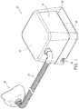
- a breathing assistance apparatus 20 is shown that is arranged and configured in accordance with certain features, aspects and advantages of the present invention.
- the breathing assistance apparatus 20 is connected to a conduit 22 and the conduit 22 is connected to a user interface 24, such as a breathing mask or the like. Any suitable user interface 24 can be used.
- the breathing assistance apparatus 20 is configured to deliver a flow of pressurized breathing gases to the user through the conduit 22 and the user interface 24.
- the illustrated breathing assistance apparatus 20 comprises a flow generator 26, which has been schematically illustrated in Figure 1 .
- the flow generator 26 can have any suitable construction.
- the flow generator 26 is a blower that draws ambient air into the breathing assistance apparatus 20 and generates the flow of pressurized breathing gases.
- the breathing assistance apparatus 20 also is configured to humidify the flow of pressurized breathing gases prior to deliver to the user.
- the illustrated breathing assistance apparatus 20 also comprises a humidification chamber 28.
- the humidification chamber 28 can be removable from the breathing assistance apparatus 20. Any suitable construction can be used for the humidification chamber 28.
- the humidification chamber 28 can be configured to contain a volume of liquid, such as water. The flow of pressurized breathing gases can pass over the volume of liquid en route to the user such that the flow of pressurized breathing gases can increase in humidity.
- the breathing assistance apparatus 20 generally comprises a main body 30.
- the main body 30 can comprise an upper housing 32 and a lower housing 34.
- the upper housing 32 and the lower housing 34 can be secured together in any suitable manner.
- the bottom of the lower housing 34 can be enclosed by a further cover.
- the lower housing 34 can include an air inlet 36 through which the flow generator 26 draws air.
- the flow generator 26 can be mounted to or within the lower housing 34.
- the lower housing 34 also can support a heating element 38.
- the liquid within the humidification chamber 28 can be heated through an interaction with the heating element 38.
- the heating element 38 can be a heater plate and the humidification chamber 28 can rest on the heater plate. Other configurations are possible.
- the main body 30 comprises at least one outer wall 40.
- the main body 30 comprises four generally vertical outer walls 40.
- An upper portion of the at least one wall 40 generally defines an opening 42.
- the opening 42 can be closed with a lid 44.
- the lid 44 can seal the opening 42 in some configurations.
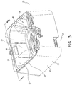
- the main body 30 contains a humidification compartment 50 that receives the humidification chamber 28.
- the humidification compartment 50 is generally defined within the at least one outer wall 40, the lid 44 and a base surface 46. More particularly, in the illustrated configuration, at least one generally vertical inner wall 52 defines at least a portion of the humidification compartment 50. Even more particularly, four generally vertical walls, including the at least one generally vertical inner wall 52, largely define the humidification compartment 50.
- a liquid containment compartment 54 can be separated from the humidification compartment 50. In some configurations, the liquid containment compartment 54 limits the travel of liquid that may spill from the humidification chamber 28. In some configurations, the liquid containment compartment 54 can limit the travel of liquid that may be spilled within the humidification compartment 50 and outside of the humidification chamber 28.
- the liquid containment compartment 54 can be positioned within the main body 30 of the breathing assistance apparatus 20. In the illustrated configuration, the liquid containment compartment 54 is integrated into the main body 30 of the breathing assistance apparatus 20. The liquid containment compartment 54 and the flow generator 26 both can be integrated into the main body 30. In some configurations, the liquid containment compartment 54 is fluidly connected to the flow generator 26 and to the humidification compartment 50. In some such configurations, the liquid containment compartment 54 is positioned between the flow generator 26 and the humidification compartment 54. In some configurations, the liquid containment compartment 54 can be positioned between the outer wall 40 and the inner wall 52 of the main body. In some configurations, the inner wall 52 separates the humidification compartment 50 from the liquid containment compartment 54.
- the liquid containment compartment 54 can include two openings.
- a first opening 56 as shown in Figure 3 , extends through the inner wall 52.
- the first opening 56 defines a gas inlet for the humidification compartment 50 and a gas outlet for the liquid containment compartment 54. Gases flowing through the first opening 56 will be received by the humidification chamber 28 and will be humidified prior to delivery to the user. In other words, with the lid 44 in position and closed, the humidification chamber 28 is sealed in position within the humidification compartment 50. Gas passing through the first opening 56 will flow into the humidification compartment 50, and from the humidification compartment, the gases will flow into the humidification chamber 28 prior to passing out of the breathing assistance apparatus 20.
- a second opening 58 defines a gas inlet into the liquid containment compartment 54 and a gas outlet for flow from a passage 66 leading from the flow generator 26.
- the first opening 56 is in the upper housing 32 and the second opening 58 is in the lower housing 34.
- the first opening 56 is offset both horizontally and vertically from the second opening.
- the first opening 56 is offset at least horizontally from the second opening 58, as shown in Figure 5 (i.e., the first opening 56 is to the right of the second opening 58).
- the first opening 56 is completely offset at least horizontally from the second opening 58.
- the two openings 56, 58 are offset in two orthogonal directions (e.g., horizontally and vertically). In some configurations, the two openings 56, 58 are offset in three orthogonal directions (horizontally in two orthogonal directions and vertically). Offset positioning of the first opening 56 relative to the second opening 58 reduces the likelihood of liquids spilling, draining, depositing or otherwise passing through the first opening 56 into the liquid containment compartment 54 passing further upstream toward the flow generator 26 relative to the liquid containment chamber 54. In other words, liquid is unlikely to easily pass through the first opening 56 and into the second opening 58. As such, liquid infiltration from the humidification chamber 28 toward the flow generator 26 can be inhibited.
- the liquid containment compartment 54 comprises at least a lower wall 70.
- the lower wall 70 can be formed as part of the lower housing 34.
- a ridge 72 can be defined on a portion of the lower housing 34.
- the illustrated ridge 72 can generally encircle a reservoir 74.
- the ridge 72 generally surrounds the second opening 58.
- Other configurations are possible.
- the second opening 58 is vertically higher than the lower wall 70.
- the second opening 58 spans a vertical distance and the lowermost portion of the second opening 58 is vertically higher than the lower wall 70.
- the lower wall 70 can span a vertical distance (i.e., not be substantially flat) and the second opening 58 is vertically higher than any portion of the lower wall 70 that is directly adjacent to the second opening 58.
- the second opening 58 is formed atop of a pedestal 76.
- the pedestal 76 can be integrally formed with the lower housing 34.
- the pedestal 76 generally encircles a passage 80 as shown in Figures 5 and 6 .
- the second opening 58 is generally canted such that the upper surface of the illustrated pedestal angles toward the first opening 56.
- at least an inner surface of the pedestal 76 that is furthest from the first opening 56 bends toward the first opening 56.
- the deflected portion of pedestal 76 that is generally adjacent the second opening 58 forms a lip 82.
- the lip 82 can help to deflect the gases flow toward the general direction of the first opening 56.
- the second opening 58 also has a narrowing region 84.
- the narrowing region 84 is disposed closest to the first opening 56 in the illustrated configuration. As shown in Figure 5 , the narrowing region 84 does not extend upward to the same extent as the lip region 82. The lip region 82 and/or the narrowing region 84 can help tailor and direct the gas flow in a desired manner. Other configurations are possible.
- At least a portion of the liquid containment compartment 54 is defined between the inner wall 52 and the outer wall 40 of the main body 30.
- at least a first wall 78 and, in some configurations, a second wall 84 can cooperate with the inner wall 52 and the outer wall 40 to define the sides of the liquid containment compartment 54.
- These walls 40, 52, 78, 84 can be integrally formed with the upper housing 32.
- the ridge 72 can match the configuration of these walls 40, 52, 78, 84. As such, the ridge 72 and these walls 40, 52, 78 and 84 can abut each other.
- a seal 86 can be positioned between the upper housing 32 and the lower housing 34. In the illustrated configuration, the seal 86 is positioned within a groove 90 (see Figure 5 ). The groove 90 may be positioned within the ridge 72.
- the seal 86 can be formed of a more resilient material than the ridge 72. As such, the seal 86 can deform upon contact with the walls 40, 52, 78, 84. The compression of the seal 86 can reduce the likelihood of liquid or gas leaks into or out of the liquid containment compartment 54.
- the seal 86 between the upper housing 32 and the lower housing 34 can reduce the likelihood of liquid migration even if the level of liquid within the liquid containment chamber 54 exceeds the height of the ridge 72.
Landscapes
- Health & Medical Sciences (AREA)
- Life Sciences & Earth Sciences (AREA)
- Public Health (AREA)
- Engineering & Computer Science (AREA)
- Anesthesiology (AREA)
- Biomedical Technology (AREA)
- Heart & Thoracic Surgery (AREA)
- Pulmonology (AREA)
- Animal Behavior & Ethology (AREA)
- Hematology (AREA)
- General Health & Medical Sciences (AREA)
- Emergency Medicine (AREA)
- Veterinary Medicine (AREA)
- Air Humidification (AREA)
- Respiratory Apparatuses And Protective Means (AREA)
- Devices For Medical Bathing And Washing (AREA)
Claims (15)
- Beatmungsvorrichtung (20) umfassend einen Hauptkörper (30), ein Befeuchtungsfach (50), das innerhalb des Hauptkörpers (30) definiert und zum Aufnehmen einer Befeuchtungskammer (28) ausgelegt ist, einen Flussgenerator (26), der innerhalb des Hauptkörpers (30) positioniert ist, wobei der Flussgenerator (26) und das Befeuchtungsfach (50) in Fluidverbindung stehen, und ein Flüssigkeitsbehälterfach (54), das innerhalb des Hauptkörpers (30) zwischen dem Flussgenerator (26) und dem Befeuchtungsfach (50) angeordnet ist, wobei das Flüssigkeitsbehälterfach (54) in Fluidverbindung sowohl mit dem Flussgenerator (26) als auch dem Befeuchtungsfach (50) steht, so dass ein Gasflussweg vom Flussgenerator (26) zum Befeuchtungsfach (50) durch das Flüssigkeitsbehälterfach (54) verläuft, und worin das Flüssigkeitsbehälterfach (54) umfasst:eine erste Öffnung (56), die einen Auslass für den Fluss von Gasen aus dem Flüssigkeitsbehälterfach (54) zum Befeuchtungsfach (50) definiert,eine zweite Öffnung (58), die einen Einlass für den Fluss von Gasen in das Flüssigkeitsbehälterfach (54) vom Flussgenerator (26) definiert, wobei die erste Öffnung (56) und die zweite Öffnung (58) des Flüssigkeitsbehälterfachs (54) in mindestens zwei orthogonalen räumlichen Richtungen voneinander versetzt sind, wobei die erste Öffnung (56) vertikal höher als die zweite Öffnung (58) positioniert ist, undeine untere Fläche, worin die zweite Öffnung (58) generell vertikal höher als die untere Fläche positioniert ist, dadurch gekennzeichnet, dass die zweite Öffnung (58) oben auf einem Sockel (76) vorgesehen ist, der sich innerhalb des Flüssigkeitsbehälterfachs (54) von der unteren Fläche des Flüssigkeitsbehälterfachs (54) erstreckt, wobei der Sockel (76) einen Durchgang umfasst, der in Fluidverbindung mit dem Flussgenerator (26) steht, um einen Teil des Gasflusswegs zu bilden.
- Beatmungsvorrichtung (20) nach Anspruch 1, worin die erste Öffnung (56) und die zweite Öffnung (58) des Flüssigkeitsbehälterfachs (54) horizontal versetzt sind, worin die erste Öffnung (56) und die zweite Öffnung (58) des Flüssigkeitsbehälterfachs (54) in drei orthogonal räumlichen Richtungen voneinander versetzt sind, bevorzugt, worin die erste Öffnung (56) und die zweite Öffnung (58) des Flüssigkeitsbehälterfachs (54) in zwei orthogonalen Richtungen horizontal versetzt sind.
- Beatmungsvorrichtung (20) nach Anspruch 1 oder 2, worin kein Abschnitt der ersten Öffnung (56) vertikal mit der zweiten Öffnung (58) ausgerichtet ist; und/oder worin kein Abschnitt der ersten Öffnung (56) horizontal mit der zweiten Öffnung (58) ausgerichtet ist.
- Beatmungsvorrichtung (20) nach einem vorhergehenden Anspruch, worin die zweite Öffnung (58) eine vertikale Distanz überbrückt und der unterste Abschnitt der zweiten Öffnung (58) vertikal höher als die untere Fläche des Flüssigkeitsbehälterfachs (54) ist, oder worin die untere Fläche des Flüssigkeitsbehälterfachs (54) eine vertikale Distanz überbrückt und die zweite Öffnung (58) vertikal höher als jeglicher Abschnitt der unteren Fläche ist, der direkt neben der zweiten Öffnung (58) ist.
- Beatmungsvorrichtung (20) nach einem vorhergehenden Anspruch, worin die zweite Öffnung (58) zur ersten Öffnung (56) hin geneigt ist und/oder worin ein unterster Abschnitt der zweiten Öffnung (58) vertikal höher als ein unterster Abschnitt der unteren Fläche des Flüssigkeitsbehälterfachs (54) ist.
- Beatmungsvorrichtung (20) nach einem vorhergehenden Anspruch, worin die zweite Öffnung (58) eine Lippe (82) aufweist, die auf einem Abschnitt der zweiten Öffnung (58) definiert ist, der auf einer gegenüberliegenden Seite der zweiten Öffnung (58) von der ersten Öffnung (56) aus ist, bevorzugt, worin die Lippe (82) aus einem Durchgang hervorsteht, der innerhalb des zur zweiten Öffnung (58) führenden Sockels (76) definiert ist, wobei der Durchgang Bestandteil des Gasflusswegs ist.
- Beatmungsvorrichtung (20) nach einem vorhergehenden Anspruch, worin die zweite Öffnung (58) einen sich verengenden Bereich (84) aufweist, der auf einem Abschnitt der zweiten Öffnung (58) definiert ist, der der ersten Öffnung (56) am nächsten angeordnet ist.
- Beatmungsvorrichtung (20) nach einem vorhergehenden Anspruch, worin die zweite Öffnung (58) in Fluidverbindung mit dem Flussgenerator (26) durch einen oder mehrere Durchgänge innerhalb des Hauptkörpers (30), die Bestandteil des Gasflusswegs sind, steht.
- Beatmungsvorrichtung (20) nach einem vorhergehenden Anspruch, worin der Hauptkörper (30) ein oberes Gehäuse (32) und ein unteres Gehäuse (34) umfasst, die dafür konfiguriert sind, aneinander gesichert zu werden, und worin das Flüssigkeitsbehälterfach (54) eine untere Fläche, die Bestandteil des unteren Gehäuses (34) des Hauptkörpers (30) ist, und eine vertikale Wand (52), die die Seiten des Flüssigkeitsbehälterfachs (54) definiert, das Bestandteil des oberen Gehäuses (32) des Hauptkörpers (30) ist, umfasst.
- Beatmungsvorrichtung (20) nach Anspruch 9, worin ein Abschnitt der vertikalen Wand (52) des Flüssigkeitsbehälterfachs (54) einem Abschnitt einer das Befeuchtungsfach (50) definierenden vertikalen Wand (52) entspricht, bevorzugt, worin sich die erste Öffnung (56) durch den Abschnitt der vertikalen Wand (52) des Flüssigkeitsbehälterfachs (54), der der vertikalen Wand (52) des Befeuchtungsfachs (50) entspricht, erstreckt.
- Beatmungsvorrichtung (20) nach Anspruch 9 oder 10, worin ein Abschnitt der vertikalen Wand (52) des Flüssigkeitsbehälterfachs (54) einem Abschnitt einer Außenwand des vom oberen Gehäuse (32) bereitgestellten Hauptkörpers (30) entspricht.
- Beatmungsvorrichtung (20) nach einem der Ansprüche 9 bis 11, worin das Flüssigkeitsbehälterfach (54) einen Steg umfasst, der die Peripherie der unteren Fläche des Flüssigkeitsbehälterfachs (54) definiert und der sich vom unteren Gehäuse (34) des Hauptkörpers (30) erstreckt, wobei der Steg mit der Konfiguration der vertikalen Wand (52) des im oberen Gehäuse (32) vorgesehenen Flüssigkeitsbehälterfachs (54) übereinstimmt, so dass der Steg des unteren Gehäuses (34) und die vertikale Wand (52) des oberen Gehäuses (32) aneinanderstoßen, um das Flüssigkeitsbehälterfach (54) zu bilden, wenn der Hauptkörper (30) zusammengebaut ist.
- Beatmungsvorrichtung (20) nach Anspruch 12, worin der Steg des Flüssigkeitsbehälterfachs (54) einen Speicher des Flüssigkeitsbehälterfachs (54) definiert und umkreist und/oder worin der Steg des Flüssigkeitsbehälterfachs (54) die zweite Öffnung (58) umgibt.
- Beatmungsvorrichtung (20) nach Anspruch 12 oder 13, worin eine Dichtung zwischen dem Steg des unteren Gehäuses (34) und der vertikalen Wand (52) des oberen Gehäuses (32), die das Flüssigkeitsbehälterfach (54) bilden, vorgesehen ist, bevorzugt, worin der Steg eine Nut umfasst und die Dichtung innerhalb der Nut vorgesehen ist.
- Beatmungsvorrichtung (20) nach einem der Ansprüche 9-14, worin der Flussgenerator (26) am oder innerhalb des unteren Gehäuses (34) des Hauptkörpers (30) montiert ist.
Priority Applications (2)
| Application Number | Priority Date | Filing Date | Title |
|---|---|---|---|
| EP23165211.6A EP4218881B1 (de) | 2014-01-30 | 2015-01-29 | Beatmungsvorrichtung mit flüssigkeitsbehälter |
| EP19192027.1A EP3590571B1 (de) | 2014-01-30 | 2015-01-29 | Beatmungsvorrichtung mit flüssigkeitsbehälter |
Applications Claiming Priority (2)
| Application Number | Priority Date | Filing Date | Title |
|---|---|---|---|
| US201461933775P | 2014-01-30 | 2014-01-30 | |
| PCT/NZ2015/050005 WO2015115916A1 (en) | 2014-01-30 | 2015-01-29 | Breathing assistance apparatus with liquid containment |
Related Child Applications (3)
| Application Number | Title | Priority Date | Filing Date |
|---|---|---|---|
| EP19192027.1A Division-Into EP3590571B1 (de) | 2014-01-30 | 2015-01-29 | Beatmungsvorrichtung mit flüssigkeitsbehälter |
| EP19192027.1A Division EP3590571B1 (de) | 2014-01-30 | 2015-01-29 | Beatmungsvorrichtung mit flüssigkeitsbehälter |
| EP23165211.6A Division EP4218881B1 (de) | 2014-01-30 | 2015-01-29 | Beatmungsvorrichtung mit flüssigkeitsbehälter |
Publications (3)
| Publication Number | Publication Date |
|---|---|
| EP3099366A1 EP3099366A1 (de) | 2016-12-07 |
| EP3099366A4 EP3099366A4 (de) | 2017-10-11 |
| EP3099366B1 true EP3099366B1 (de) | 2019-10-30 |
Family
ID=53757394
Family Applications (3)
| Application Number | Title | Priority Date | Filing Date |
|---|---|---|---|
| EP15743509.0A Active EP3099366B1 (de) | 2014-01-30 | 2015-01-29 | Beatmungsvorrichtung mit flüssigkeitsbehälter |
| EP23165211.6A Active EP4218881B1 (de) | 2014-01-30 | 2015-01-29 | Beatmungsvorrichtung mit flüssigkeitsbehälter |
| EP19192027.1A Active EP3590571B1 (de) | 2014-01-30 | 2015-01-29 | Beatmungsvorrichtung mit flüssigkeitsbehälter |
Family Applications After (2)
| Application Number | Title | Priority Date | Filing Date |
|---|---|---|---|
| EP23165211.6A Active EP4218881B1 (de) | 2014-01-30 | 2015-01-29 | Beatmungsvorrichtung mit flüssigkeitsbehälter |
| EP19192027.1A Active EP3590571B1 (de) | 2014-01-30 | 2015-01-29 | Beatmungsvorrichtung mit flüssigkeitsbehälter |
Country Status (10)
| Country | Link |
|---|---|
| US (3) | US10493229B2 (de) |
| EP (3) | EP3099366B1 (de) |
| JP (4) | JP6586097B2 (de) |
| CN (2) | CN111068157B (de) |
| AU (5) | AU2015211502B2 (de) |
| BR (1) | BR112016016630B1 (de) |
| CA (2) | CA2936923C (de) |
| GB (2) | GB2559901B (de) |
| SG (2) | SG11201605793SA (de) |
| WO (1) | WO2015115916A1 (de) |
Families Citing this family (7)
| Publication number | Priority date | Publication date | Assignee | Title |
|---|---|---|---|---|
| BR112016016630B1 (pt) | 2014-01-30 | 2021-12-07 | Fisher & Paykel Healthcare Limited | Aparelho de assistência respiratória com contenção de líquidos |
| USD790683S1 (en) * | 2015-03-11 | 2017-06-27 | Resmed Limited | Pressurized air delivery console |
| EP3978058B1 (de) * | 2016-07-01 | 2025-01-15 | Fisher & Paykel Healthcare Limited | Verbesserungen im zusammenhang mit einer atemvorrichtung |
| US10957966B2 (en) | 2018-02-06 | 2021-03-23 | Barkan Mounts Ltd | Wall mount for screens with an integrated antenna |
| CN117065173A (zh) * | 2018-10-26 | 2023-11-17 | 北京怡和嘉业医疗科技股份有限公司 | 加湿组件和呼吸通气设备 |
| US20230381444A1 (en) * | 2020-10-29 | 2023-11-30 | ResMed Pty Ltd | Assembly for diverting liquid from a respiratory device |
| CN114272487B (zh) * | 2021-12-27 | 2024-05-03 | 北京谊安健康科技有限公司 | 一种防止液体回流的湿化装置 |
Family Cites Families (27)
| Publication number | Priority date | Publication date | Assignee | Title |
|---|---|---|---|---|
| US4028444A (en) * | 1974-03-25 | 1977-06-07 | Chemetron Corporation | Humidifier and automatic control system therefor |
| US6398197B1 (en) | 1999-05-10 | 2002-06-04 | Fisher & Paykel Limited | Water chamber |
| JP4420605B2 (ja) * | 2001-02-16 | 2010-02-24 | レスメド・リミテッド | 加湿器入口を介しての液の逆流を防ぐ構造を有する加湿器 |
| DE10226160B4 (de) * | 2002-06-12 | 2009-06-18 | Hoffrichter Gmbh | Luftbefeuchter für ein Beatmungsgerät |
| US20030188746A1 (en) * | 2003-05-13 | 2003-10-09 | Roger Daugherty | Apparatus and method for humidification of inspired gases |
| CN105194774B (zh) * | 2003-06-20 | 2018-06-01 | 瑞思迈有限公司 | 带有加湿器的可吸入气体设备 |
| AU2013201490B2 (en) * | 2003-06-20 | 2014-09-25 | ResMed Pty Ltd | Breathable Gas Apparatus with Humidifier |
| AU2003903139A0 (en) * | 2003-06-20 | 2003-07-03 | Resmed Limited | Breathable gas apparatus with humidifier |
| CN2695846Y (zh) * | 2003-08-07 | 2005-04-27 | 北京杰富瑞科技有限公司 | 防反流加温湿化装置 |
| EP3747494B1 (de) * | 2003-08-20 | 2023-09-27 | Fisher & Paykel Healthcare Limited | Wasserkammer für befeuchter |
| CN103157165B (zh) * | 2005-08-15 | 2016-12-28 | 瑞思迈有限公司 | 用于cpap装置的加湿器和/或气流发生器 |
| US8701662B2 (en) * | 2005-09-27 | 2014-04-22 | Ric Investments, Llc | Humidifier with back-flow prevention valve |
| WO2008024001A1 (en) * | 2006-08-25 | 2008-02-28 | Fisher & Paykel Healthcare Limited | Humidifier with internal heating element and heater plate |
| JP5518480B2 (ja) * | 2006-11-06 | 2014-06-11 | フィッシャー アンド ペイケル ヘルスケア リミテッド | 一体型加湿器チャンバおよびlid |
| US8905023B2 (en) * | 2007-10-05 | 2014-12-09 | Vapotherm, Inc. | Hyperthermic humidification system |
| CN102083492B (zh) * | 2008-06-27 | 2015-02-25 | 皇家飞利浦电子股份有限公司 | 用于呼吸系统的加湿器 |
| NZ607629A (en) * | 2008-09-17 | 2014-07-25 | Resmed Ltd | Humidification of respiratory gases |
| KR101532576B1 (ko) * | 2008-11-28 | 2015-06-30 | 엘지전자 주식회사 | 가습기 |
| EP2437838B1 (de) * | 2009-06-05 | 2017-01-11 | Fisher & Paykel Healthcare Limited | Erwärmungsbasis für einen befeuchter |
| CA2784852C (en) * | 2009-12-23 | 2018-02-27 | Fisher & Paykel Healthcare Limited | Humidified gases delivery apparatus and methods for controlling same |
| US9545492B2 (en) * | 2011-03-14 | 2017-01-17 | Koninklijke Philips N.V. | Humidifier with liquid ingress protection |
| JP6130353B2 (ja) * | 2011-04-05 | 2017-05-17 | レスメド・リミテッドResMed Limited | 呼吸装置 |
| DE11005292T1 (de) * | 2011-06-29 | 2013-07-25 | Healthc'air | Behälter für Gerät zur Atmungsunterstützung |
| US10213573B2 (en) * | 2011-12-22 | 2019-02-26 | Resmed Limited | Humidifiers for respiratory apparatus |
| EP3708213B1 (de) | 2012-03-15 | 2022-11-02 | ResMed Pty Ltd | Heizvorrichtung |
| CN202654514U (zh) * | 2012-05-22 | 2013-01-09 | 北京怡和嘉业医疗科技有限公司 | 加湿设备和具有该加湿设备的通气治疗设备 |
| BR112016016630B1 (pt) | 2014-01-30 | 2021-12-07 | Fisher & Paykel Healthcare Limited | Aparelho de assistência respiratória com contenção de líquidos |
-
2015
- 2015-01-29 BR BR112016016630-2A patent/BR112016016630B1/pt active IP Right Grant
- 2015-01-29 CA CA2936923A patent/CA2936923C/en active Active
- 2015-01-29 EP EP15743509.0A patent/EP3099366B1/de active Active
- 2015-01-29 SG SG11201605793SA patent/SG11201605793SA/en unknown
- 2015-01-29 CN CN201911341572.5A patent/CN111068157B/zh active Active
- 2015-01-29 CA CA3159009A patent/CA3159009A1/en active Pending
- 2015-01-29 US US15/113,787 patent/US10493229B2/en active Active
- 2015-01-29 GB GB1805636.6A patent/GB2559901B/en active Active
- 2015-01-29 WO PCT/NZ2015/050005 patent/WO2015115916A1/en not_active Ceased
- 2015-01-29 JP JP2016549441A patent/JP6586097B2/ja active Active
- 2015-01-29 CN CN201580006405.9A patent/CN105939748B/zh active Active
- 2015-01-29 GB GB1612153.5A patent/GB2541117B/en active Active
- 2015-01-29 AU AU2015211502A patent/AU2015211502B2/en active Active
- 2015-01-29 EP EP23165211.6A patent/EP4218881B1/de active Active
- 2015-01-29 SG SG10201907307SA patent/SG10201907307SA/en unknown
- 2015-01-29 EP EP19192027.1A patent/EP3590571B1/de active Active
-
2019
- 2019-09-06 JP JP2019162901A patent/JP6974406B2/ja active Active
- 2019-10-30 US US16/668,764 patent/US11305090B2/en active Active
-
2020
- 2020-04-08 AU AU2020202424A patent/AU2020202424B2/en active Active
-
2021
- 2021-11-04 JP JP2021180027A patent/JP2022016476A/ja active Pending
- 2021-11-25 AU AU2021273596A patent/AU2021273596B2/en active Active
-
2022
- 2022-03-15 US US17/654,894 patent/US20220280745A1/en active Pending
-
2023
- 2023-12-04 AU AU2023274229A patent/AU2023274229B2/en active Active
- 2023-12-25 JP JP2023218243A patent/JP2024028308A/ja active Pending
-
2026
- 2026-03-02 AU AU2026201570A patent/AU2026201570A1/en active Pending
Non-Patent Citations (1)
| Title |
|---|
| None * |
Also Published As
Similar Documents
| Publication | Publication Date | Title |
|---|---|---|
| US11305090B2 (en) | Breathing assistance apparatus with liquid containment | |
| US5943473A (en) | Heated cartridge humidifier | |
| EP2686053B1 (de) | Befeuchter mit flüssigkeitseindringungsschutz | |
| JP2005538817A (ja) | 加湿器用水充填装置 | |
| EP4294487B1 (de) | Integrierter befeuchter mit wassereintrittsschutz | |
| EP2842589A2 (de) | Befeuchter für Beatmungsvorrichtung | |
| US20170336086A1 (en) | Liquid container for gas humidification and gas humidification method | |
| ES2783978T3 (es) | Depósito de agua mejorado para un humidificador de gas calefactor alimentado por un ventilador médico |
Legal Events
| Date | Code | Title | Description |
|---|---|---|---|
| PUAI | Public reference made under article 153(3) epc to a published international application that has entered the european phase |
Free format text: ORIGINAL CODE: 0009012 |
|
| STAA | Information on the status of an ep patent application or granted ep patent |
Free format text: STATUS: REQUEST FOR EXAMINATION WAS MADE |
|
| 17P | Request for examination filed |
Effective date: 20160713 |
|
| AK | Designated contracting states |
Kind code of ref document: A1 Designated state(s): AL AT BE BG CH CY CZ DE DK EE ES FI FR GB GR HR HU IE IS IT LI LT LU LV MC MK MT NL NO PL PT RO RS SE SI SK SM TR |
|
| AX | Request for extension of the european patent |
Extension state: BA ME |
|
| DAX | Request for extension of the european patent (deleted) | ||
| A4 | Supplementary search report drawn up and despatched |
Effective date: 20170907 |
|
| RIC1 | Information provided on ipc code assigned before grant |
Ipc: A61M 16/16 20060101AFI20170901BHEP |
|
| GRAP | Despatch of communication of intention to grant a patent |
Free format text: ORIGINAL CODE: EPIDOSNIGR1 |
|
| STAA | Information on the status of an ep patent application or granted ep patent |
Free format text: STATUS: GRANT OF PATENT IS INTENDED |
|
| INTG | Intention to grant announced |
Effective date: 20190409 |
|
| GRAS | Grant fee paid |
Free format text: ORIGINAL CODE: EPIDOSNIGR3 |
|
| GRAA | (expected) grant |
Free format text: ORIGINAL CODE: 0009210 |
|
| STAA | Information on the status of an ep patent application or granted ep patent |
Free format text: STATUS: THE PATENT HAS BEEN GRANTED |
|
| RBV | Designated contracting states (corrected) |
Designated state(s): AL AT BE BG CH CY CZ DE DK EE ES FI FR GR HR HU IE IS IT LI LT LU LV MC MK MT NL NO PL PT RO RS SE SI SK SM TR |
|
| AK | Designated contracting states |
Kind code of ref document: B1 Designated state(s): AL AT BE BG CH CY CZ DE DK EE ES FI FR GR HR HU IE IS IT LI LT LU LV MC MK MT NL NO PL PT RO RS SE SI SK SM TR |
|
| RAP1 | Party data changed (applicant data changed or rights of an application transferred) |
Owner name: FISHER & PAYKEL HEALTHCARE LIMITED |
|
| REG | Reference to a national code |
Ref country code: CH Ref legal event code: EP |
|
| REG | Reference to a national code |
Ref country code: AT Ref legal event code: REF Ref document number: 1195486 Country of ref document: AT Kind code of ref document: T Effective date: 20191115 |
|
| REG | Reference to a national code |
Ref country code: DE Ref legal event code: R096 Ref document number: 602015040712 Country of ref document: DE |
|
| REG | Reference to a national code |
Ref country code: IE Ref legal event code: FG4D |
|
| REG | Reference to a national code |
Ref country code: LT Ref legal event code: MG4D |
|
| PG25 | Lapsed in a contracting state [announced via postgrant information from national office to epo] |
Ref country code: FI Free format text: LAPSE BECAUSE OF FAILURE TO SUBMIT A TRANSLATION OF THE DESCRIPTION OR TO PAY THE FEE WITHIN THE PRESCRIBED TIME-LIMIT Effective date: 20191030 Ref country code: BG Free format text: LAPSE BECAUSE OF FAILURE TO SUBMIT A TRANSLATION OF THE DESCRIPTION OR TO PAY THE FEE WITHIN THE PRESCRIBED TIME-LIMIT Effective date: 20200130 Ref country code: LT Free format text: LAPSE BECAUSE OF FAILURE TO SUBMIT A TRANSLATION OF THE DESCRIPTION OR TO PAY THE FEE WITHIN THE PRESCRIBED TIME-LIMIT Effective date: 20191030 Ref country code: PL Free format text: LAPSE BECAUSE OF FAILURE TO SUBMIT A TRANSLATION OF THE DESCRIPTION OR TO PAY THE FEE WITHIN THE PRESCRIBED TIME-LIMIT Effective date: 20191030 Ref country code: GR Free format text: LAPSE BECAUSE OF FAILURE TO SUBMIT A TRANSLATION OF THE DESCRIPTION OR TO PAY THE FEE WITHIN THE PRESCRIBED TIME-LIMIT Effective date: 20200131 Ref country code: NO Free format text: LAPSE BECAUSE OF FAILURE TO SUBMIT A TRANSLATION OF THE DESCRIPTION OR TO PAY THE FEE WITHIN THE PRESCRIBED TIME-LIMIT Effective date: 20200130 Ref country code: LV Free format text: LAPSE BECAUSE OF FAILURE TO SUBMIT A TRANSLATION OF THE DESCRIPTION OR TO PAY THE FEE WITHIN THE PRESCRIBED TIME-LIMIT Effective date: 20191030 Ref country code: SE Free format text: LAPSE BECAUSE OF FAILURE TO SUBMIT A TRANSLATION OF THE DESCRIPTION OR TO PAY THE FEE WITHIN THE PRESCRIBED TIME-LIMIT Effective date: 20191030 Ref country code: NL Free format text: LAPSE BECAUSE OF FAILURE TO SUBMIT A TRANSLATION OF THE DESCRIPTION OR TO PAY THE FEE WITHIN THE PRESCRIBED TIME-LIMIT Effective date: 20191030 Ref country code: PT Free format text: LAPSE BECAUSE OF FAILURE TO SUBMIT A TRANSLATION OF THE DESCRIPTION OR TO PAY THE FEE WITHIN THE PRESCRIBED TIME-LIMIT Effective date: 20200302 |
|
| REG | Reference to a national code |
Ref country code: NL Ref legal event code: MP Effective date: 20191030 |
|
| PG25 | Lapsed in a contracting state [announced via postgrant information from national office to epo] |
Ref country code: RS Free format text: LAPSE BECAUSE OF FAILURE TO SUBMIT A TRANSLATION OF THE DESCRIPTION OR TO PAY THE FEE WITHIN THE PRESCRIBED TIME-LIMIT Effective date: 20191030 Ref country code: HR Free format text: LAPSE BECAUSE OF FAILURE TO SUBMIT A TRANSLATION OF THE DESCRIPTION OR TO PAY THE FEE WITHIN THE PRESCRIBED TIME-LIMIT Effective date: 20191030 Ref country code: IS Free format text: LAPSE BECAUSE OF FAILURE TO SUBMIT A TRANSLATION OF THE DESCRIPTION OR TO PAY THE FEE WITHIN THE PRESCRIBED TIME-LIMIT Effective date: 20200229 |
|
| PG25 | Lapsed in a contracting state [announced via postgrant information from national office to epo] |
Ref country code: AL Free format text: LAPSE BECAUSE OF FAILURE TO SUBMIT A TRANSLATION OF THE DESCRIPTION OR TO PAY THE FEE WITHIN THE PRESCRIBED TIME-LIMIT Effective date: 20191030 |
|
| PG25 | Lapsed in a contracting state [announced via postgrant information from national office to epo] |
Ref country code: EE Free format text: LAPSE BECAUSE OF FAILURE TO SUBMIT A TRANSLATION OF THE DESCRIPTION OR TO PAY THE FEE WITHIN THE PRESCRIBED TIME-LIMIT Effective date: 20191030 Ref country code: DK Free format text: LAPSE BECAUSE OF FAILURE TO SUBMIT A TRANSLATION OF THE DESCRIPTION OR TO PAY THE FEE WITHIN THE PRESCRIBED TIME-LIMIT Effective date: 20191030 Ref country code: RO Free format text: LAPSE BECAUSE OF FAILURE TO SUBMIT A TRANSLATION OF THE DESCRIPTION OR TO PAY THE FEE WITHIN THE PRESCRIBED TIME-LIMIT Effective date: 20191030 Ref country code: CZ Free format text: LAPSE BECAUSE OF FAILURE TO SUBMIT A TRANSLATION OF THE DESCRIPTION OR TO PAY THE FEE WITHIN THE PRESCRIBED TIME-LIMIT Effective date: 20191030 Ref country code: ES Free format text: LAPSE BECAUSE OF FAILURE TO SUBMIT A TRANSLATION OF THE DESCRIPTION OR TO PAY THE FEE WITHIN THE PRESCRIBED TIME-LIMIT Effective date: 20191030 |
|
| REG | Reference to a national code |
Ref country code: DE Ref legal event code: R097 Ref document number: 602015040712 Country of ref document: DE |
|
| REG | Reference to a national code |
Ref country code: AT Ref legal event code: MK05 Ref document number: 1195486 Country of ref document: AT Kind code of ref document: T Effective date: 20191030 |
|
| PG25 | Lapsed in a contracting state [announced via postgrant information from national office to epo] |
Ref country code: MC Free format text: LAPSE BECAUSE OF FAILURE TO SUBMIT A TRANSLATION OF THE DESCRIPTION OR TO PAY THE FEE WITHIN THE PRESCRIBED TIME-LIMIT Effective date: 20191030 Ref country code: SM Free format text: LAPSE BECAUSE OF FAILURE TO SUBMIT A TRANSLATION OF THE DESCRIPTION OR TO PAY THE FEE WITHIN THE PRESCRIBED TIME-LIMIT Effective date: 20191030 Ref country code: IT Free format text: LAPSE BECAUSE OF FAILURE TO SUBMIT A TRANSLATION OF THE DESCRIPTION OR TO PAY THE FEE WITHIN THE PRESCRIBED TIME-LIMIT Effective date: 20191030 Ref country code: SK Free format text: LAPSE BECAUSE OF FAILURE TO SUBMIT A TRANSLATION OF THE DESCRIPTION OR TO PAY THE FEE WITHIN THE PRESCRIBED TIME-LIMIT Effective date: 20191030 |
|
| REG | Reference to a national code |
Ref country code: CH Ref legal event code: PL |
|
| PLBE | No opposition filed within time limit |
Free format text: ORIGINAL CODE: 0009261 |
|
| STAA | Information on the status of an ep patent application or granted ep patent |
Free format text: STATUS: NO OPPOSITION FILED WITHIN TIME LIMIT |
|
| 26N | No opposition filed |
Effective date: 20200731 |
|
| REG | Reference to a national code |
Ref country code: BE Ref legal event code: MM Effective date: 20200131 |
|
| PG25 | Lapsed in a contracting state [announced via postgrant information from national office to epo] |
Ref country code: LU Free format text: LAPSE BECAUSE OF NON-PAYMENT OF DUE FEES Effective date: 20200129 |
|
| PG25 | Lapsed in a contracting state [announced via postgrant information from national office to epo] |
Ref country code: CH Free format text: LAPSE BECAUSE OF NON-PAYMENT OF DUE FEES Effective date: 20200131 Ref country code: BE Free format text: LAPSE BECAUSE OF NON-PAYMENT OF DUE FEES Effective date: 20200131 Ref country code: LI Free format text: LAPSE BECAUSE OF NON-PAYMENT OF DUE FEES Effective date: 20200131 Ref country code: SI Free format text: LAPSE BECAUSE OF FAILURE TO SUBMIT A TRANSLATION OF THE DESCRIPTION OR TO PAY THE FEE WITHIN THE PRESCRIBED TIME-LIMIT Effective date: 20191030 Ref country code: AT Free format text: LAPSE BECAUSE OF FAILURE TO SUBMIT A TRANSLATION OF THE DESCRIPTION OR TO PAY THE FEE WITHIN THE PRESCRIBED TIME-LIMIT Effective date: 20191030 |
|
| PG25 | Lapsed in a contracting state [announced via postgrant information from national office to epo] |
Ref country code: IE Free format text: LAPSE BECAUSE OF NON-PAYMENT OF DUE FEES Effective date: 20200129 |
|
| PG25 | Lapsed in a contracting state [announced via postgrant information from national office to epo] |
Ref country code: TR Free format text: LAPSE BECAUSE OF FAILURE TO SUBMIT A TRANSLATION OF THE DESCRIPTION OR TO PAY THE FEE WITHIN THE PRESCRIBED TIME-LIMIT Effective date: 20191030 Ref country code: MT Free format text: LAPSE BECAUSE OF FAILURE TO SUBMIT A TRANSLATION OF THE DESCRIPTION OR TO PAY THE FEE WITHIN THE PRESCRIBED TIME-LIMIT Effective date: 20191030 Ref country code: CY Free format text: LAPSE BECAUSE OF FAILURE TO SUBMIT A TRANSLATION OF THE DESCRIPTION OR TO PAY THE FEE WITHIN THE PRESCRIBED TIME-LIMIT Effective date: 20191030 |
|
| PG25 | Lapsed in a contracting state [announced via postgrant information from national office to epo] |
Ref country code: MK Free format text: LAPSE BECAUSE OF FAILURE TO SUBMIT A TRANSLATION OF THE DESCRIPTION OR TO PAY THE FEE WITHIN THE PRESCRIBED TIME-LIMIT Effective date: 20191030 |
|
| P01 | Opt-out of the competence of the unified patent court (upc) registered |
Effective date: 20230526 |
|
| PGFP | Annual fee paid to national office [announced via postgrant information from national office to epo] |
Ref country code: FR Payment date: 20251217 Year of fee payment: 12 |
|
| PGFP | Annual fee paid to national office [announced via postgrant information from national office to epo] |
Ref country code: DE Payment date: 20251217 Year of fee payment: 12 |