EP3099270B1 - Pararenal and thoracic arch stent graft - Google Patents
Pararenal and thoracic arch stent graft Download PDFInfo
- Publication number
- EP3099270B1 EP3099270B1 EP15743077.8A EP15743077A EP3099270B1 EP 3099270 B1 EP3099270 B1 EP 3099270B1 EP 15743077 A EP15743077 A EP 15743077A EP 3099270 B1 EP3099270 B1 EP 3099270B1
- Authority
- EP
- European Patent Office
- Prior art keywords
- stent graft
- opening
- main body
- diaphragm
- disclosure
- Prior art date
- Legal status (The legal status is an assumption and is not a legal conclusion. Google has not performed a legal analysis and makes no representation as to the accuracy of the status listed.)
- Active
Links
- 210000000115 thoracic cavity Anatomy 0.000 title description 5
- 238000007789 sealing Methods 0.000 description 54
- 230000009278 visceral effect Effects 0.000 description 26
- 239000000463 material Substances 0.000 description 21
- 230000017531 blood circulation Effects 0.000 description 20
- 210000001367 artery Anatomy 0.000 description 18
- 238000000034 method Methods 0.000 description 15
- 206010002329 Aneurysm Diseases 0.000 description 12
- 210000002254 renal artery Anatomy 0.000 description 10
- 210000000709 aorta Anatomy 0.000 description 9
- 210000005166 vasculature Anatomy 0.000 description 8
- 210000000702 aorta abdominal Anatomy 0.000 description 7
- 210000002434 celiac artery Anatomy 0.000 description 7
- 210000002376 aorta thoracic Anatomy 0.000 description 6
- 239000012530 fluid Substances 0.000 description 6
- -1 poly(ethylene terephthalate) Polymers 0.000 description 6
- 229910001000 nickel titanium Inorganic materials 0.000 description 5
- 239000008280 blood Substances 0.000 description 4
- 210000004369 blood Anatomy 0.000 description 4
- 238000001727 in vivo Methods 0.000 description 4
- 206010038366 Renal aneurysm Diseases 0.000 description 3
- 238000004873 anchoring Methods 0.000 description 3
- 230000008901 benefit Effects 0.000 description 3
- 230000036772 blood pressure Effects 0.000 description 3
- 238000010276 construction Methods 0.000 description 3
- 239000004744 fabric Substances 0.000 description 3
- 238000007373 indentation Methods 0.000 description 3
- 230000004048 modification Effects 0.000 description 3
- 238000012986 modification Methods 0.000 description 3
- HLXZNVUGXRDIFK-UHFFFAOYSA-N nickel titanium Chemical compound [Ti].[Ti].[Ti].[Ti].[Ti].[Ti].[Ti].[Ti].[Ti].[Ti].[Ti].[Ni].[Ni].[Ni].[Ni].[Ni].[Ni].[Ni].[Ni].[Ni].[Ni].[Ni].[Ni].[Ni].[Ni] HLXZNVUGXRDIFK-UHFFFAOYSA-N 0.000 description 3
- 229920002635 polyurethane Polymers 0.000 description 3
- 239000004814 polyurethane Substances 0.000 description 3
- 230000007704 transition Effects 0.000 description 3
- HTTJABKRGRZYRN-UHFFFAOYSA-N Heparin Chemical compound OC1C(NC(=O)C)C(O)OC(COS(O)(=O)=O)C1OC1C(OS(O)(=O)=O)C(O)C(OC2C(C(OS(O)(=O)=O)C(OC3C(C(O)C(O)C(O3)C(O)=O)OS(O)(=O)=O)C(CO)O2)NS(O)(=O)=O)C(C(O)=O)O1 HTTJABKRGRZYRN-UHFFFAOYSA-N 0.000 description 2
- PXHVJJICTQNCMI-UHFFFAOYSA-N Nickel Chemical compound [Ni] PXHVJJICTQNCMI-UHFFFAOYSA-N 0.000 description 2
- 208000007474 aortic aneurysm Diseases 0.000 description 2
- 229920000249 biocompatible polymer Polymers 0.000 description 2
- 210000001168 carotid artery common Anatomy 0.000 description 2
- 239000003795 chemical substances by application Substances 0.000 description 2
- 239000002783 friction material Substances 0.000 description 2
- 229960002897 heparin Drugs 0.000 description 2
- 229920000669 heparin Polymers 0.000 description 2
- 210000003090 iliac artery Anatomy 0.000 description 2
- 210000003734 kidney Anatomy 0.000 description 2
- 230000007246 mechanism Effects 0.000 description 2
- 210000001363 mesenteric artery superior Anatomy 0.000 description 2
- 239000004033 plastic Substances 0.000 description 2
- 229920003023 plastic Polymers 0.000 description 2
- 229920001343 polytetrafluoroethylene Polymers 0.000 description 2
- 239000004810 polytetrafluoroethylene Substances 0.000 description 2
- 239000010935 stainless steel Substances 0.000 description 2
- 229910001220 stainless steel Inorganic materials 0.000 description 2
- 210000003270 subclavian artery Anatomy 0.000 description 2
- 210000001519 tissue Anatomy 0.000 description 2
- 230000002792 vascular Effects 0.000 description 2
- 238000003466 welding Methods 0.000 description 2
- BVKZGUZCCUSVTD-UHFFFAOYSA-L Carbonate Chemical compound [O-]C([O-])=O BVKZGUZCCUSVTD-UHFFFAOYSA-L 0.000 description 1
- 208000001750 Endoleak Diseases 0.000 description 1
- 102000010834 Extracellular Matrix Proteins Human genes 0.000 description 1
- 108010037362 Extracellular Matrix Proteins Proteins 0.000 description 1
- AEMRFAOFKBGASW-UHFFFAOYSA-N Glycolic acid Polymers OCC(O)=O AEMRFAOFKBGASW-UHFFFAOYSA-N 0.000 description 1
- 229920000544 Gore-Tex Polymers 0.000 description 1
- 206010061307 Neck deformity Diseases 0.000 description 1
- 229910000990 Ni alloy Inorganic materials 0.000 description 1
- 206010033892 Paraplegia Diseases 0.000 description 1
- 229920000954 Polyglycolide Polymers 0.000 description 1
- 206010064396 Stent-graft endoleak Diseases 0.000 description 1
- 208000007536 Thrombosis Diseases 0.000 description 1
- 229910001069 Ti alloy Inorganic materials 0.000 description 1
- HZEWFHLRYVTOIW-UHFFFAOYSA-N [Ti].[Ni] Chemical compound [Ti].[Ni] HZEWFHLRYVTOIW-UHFFFAOYSA-N 0.000 description 1
- 208000002223 abdominal aortic aneurysm Diseases 0.000 description 1
- 239000000853 adhesive Substances 0.000 description 1
- 238000004026 adhesive bonding Methods 0.000 description 1
- 230000001070 adhesive effect Effects 0.000 description 1
- 210000001765 aortic valve Anatomy 0.000 description 1
- 230000001174 ascending effect Effects 0.000 description 1
- 230000004888 barrier function Effects 0.000 description 1
- 230000002457 bidirectional effect Effects 0.000 description 1
- 239000000560 biocompatible material Substances 0.000 description 1
- 230000015572 biosynthetic process Effects 0.000 description 1
- 230000000903 blocking effect Effects 0.000 description 1
- 239000010836 blood and blood product Substances 0.000 description 1
- 229940125691 blood product Drugs 0.000 description 1
- 235000013877 carbamide Nutrition 0.000 description 1
- 238000007385 chemical modification Methods 0.000 description 1
- 239000011248 coating agent Substances 0.000 description 1
- 238000000576 coating method Methods 0.000 description 1
- 229920001577 copolymer Polymers 0.000 description 1
- 210000004351 coronary vessel Anatomy 0.000 description 1
- 238000005520 cutting process Methods 0.000 description 1
- 238000011161 development Methods 0.000 description 1
- 235000013870 dimethyl polysiloxane Nutrition 0.000 description 1
- 239000004205 dimethyl polysiloxane Substances 0.000 description 1
- KPUWHANPEXNPJT-UHFFFAOYSA-N disiloxane Chemical class [SiH3]O[SiH3] KPUWHANPEXNPJT-UHFFFAOYSA-N 0.000 description 1
- 230000007717 exclusion Effects 0.000 description 1
- 229920000295 expanded polytetrafluoroethylene Polymers 0.000 description 1
- 210000002744 extracellular matrix Anatomy 0.000 description 1
- 229920002313 fluoropolymer Polymers 0.000 description 1
- 125000000524 functional group Chemical group 0.000 description 1
- PCHJSUWPFVWCPO-UHFFFAOYSA-N gold Chemical compound [Au] PCHJSUWPFVWCPO-UHFFFAOYSA-N 0.000 description 1
- 239000010931 gold Substances 0.000 description 1
- 229910052737 gold Inorganic materials 0.000 description 1
- 238000010559 graft polymerization reaction Methods 0.000 description 1
- 230000003993 interaction Effects 0.000 description 1
- 239000003550 marker Substances 0.000 description 1
- 239000011159 matrix material Substances 0.000 description 1
- 238000005259 measurement Methods 0.000 description 1
- 229910052751 metal Inorganic materials 0.000 description 1
- 239000002184 metal Substances 0.000 description 1
- 150000002739 metals Chemical class 0.000 description 1
- 230000002093 peripheral effect Effects 0.000 description 1
- 229920000435 poly(dimethylsiloxane) Polymers 0.000 description 1
- 229920000747 poly(lactic acid) Polymers 0.000 description 1
- 229920000728 polyester Polymers 0.000 description 1
- 229920000139 polyethylene terephthalate Polymers 0.000 description 1
- 239000005020 polyethylene terephthalate Substances 0.000 description 1
- 229920000642 polymer Polymers 0.000 description 1
- 229920001296 polysiloxane Polymers 0.000 description 1
- 229920003226 polyurethane urea Polymers 0.000 description 1
- 229920002981 polyvinylidene fluoride Polymers 0.000 description 1
- 230000002787 reinforcement Effects 0.000 description 1
- 230000004044 response Effects 0.000 description 1
- 210000002966 serum Anatomy 0.000 description 1
- 239000007787 solid Substances 0.000 description 1
- 210000000278 spinal cord Anatomy 0.000 description 1
- 239000000126 substance Substances 0.000 description 1
- 238000010408 sweeping Methods 0.000 description 1
- 229920002994 synthetic fiber Polymers 0.000 description 1
- 150000003672 ureas Chemical class 0.000 description 1
- 238000012800 visualization Methods 0.000 description 1
Images


Classifications
-
- A—HUMAN NECESSITIES
- A61—MEDICAL OR VETERINARY SCIENCE; HYGIENE
- A61F—FILTERS IMPLANTABLE INTO BLOOD VESSELS; PROSTHESES; DEVICES PROVIDING PATENCY TO, OR PREVENTING COLLAPSING OF, TUBULAR STRUCTURES OF THE BODY, e.g. STENTS; ORTHOPAEDIC, NURSING OR CONTRACEPTIVE DEVICES; FOMENTATION; TREATMENT OR PROTECTION OF EYES OR EARS; BANDAGES, DRESSINGS OR ABSORBENT PADS; FIRST-AID KITS
- A61F2/00—Filters implantable into blood vessels; Prostheses, i.e. artificial substitutes or replacements for parts of the body; Appliances for connecting them with the body; Devices providing patency to, or preventing collapsing of, tubular structures of the body, e.g. stents
- A61F2/02—Prostheses implantable into the body
- A61F2/04—Hollow or tubular parts of organs, e.g. bladders, tracheae, bronchi or bile ducts
- A61F2/06—Blood vessels
- A61F2/07—Stent-grafts
-
- A—HUMAN NECESSITIES
- A61—MEDICAL OR VETERINARY SCIENCE; HYGIENE
- A61F—FILTERS IMPLANTABLE INTO BLOOD VESSELS; PROSTHESES; DEVICES PROVIDING PATENCY TO, OR PREVENTING COLLAPSING OF, TUBULAR STRUCTURES OF THE BODY, e.g. STENTS; ORTHOPAEDIC, NURSING OR CONTRACEPTIVE DEVICES; FOMENTATION; TREATMENT OR PROTECTION OF EYES OR EARS; BANDAGES, DRESSINGS OR ABSORBENT PADS; FIRST-AID KITS
- A61F2/00—Filters implantable into blood vessels; Prostheses, i.e. artificial substitutes or replacements for parts of the body; Appliances for connecting them with the body; Devices providing patency to, or preventing collapsing of, tubular structures of the body, e.g. stents
- A61F2/02—Prostheses implantable into the body
- A61F2/24—Heart valves ; Vascular valves, e.g. venous valves; Heart implants, e.g. passive devices for improving the function of the native valve or the heart muscle; Transmyocardial revascularisation [TMR] devices; Valves implantable in the body
- A61F2/2412—Heart valves ; Vascular valves, e.g. venous valves; Heart implants, e.g. passive devices for improving the function of the native valve or the heart muscle; Transmyocardial revascularisation [TMR] devices; Valves implantable in the body with soft flexible valve members, e.g. tissue valves shaped like natural valves
-
- A—HUMAN NECESSITIES
- A61—MEDICAL OR VETERINARY SCIENCE; HYGIENE
- A61F—FILTERS IMPLANTABLE INTO BLOOD VESSELS; PROSTHESES; DEVICES PROVIDING PATENCY TO, OR PREVENTING COLLAPSING OF, TUBULAR STRUCTURES OF THE BODY, e.g. STENTS; ORTHOPAEDIC, NURSING OR CONTRACEPTIVE DEVICES; FOMENTATION; TREATMENT OR PROTECTION OF EYES OR EARS; BANDAGES, DRESSINGS OR ABSORBENT PADS; FIRST-AID KITS
- A61F2/00—Filters implantable into blood vessels; Prostheses, i.e. artificial substitutes or replacements for parts of the body; Appliances for connecting them with the body; Devices providing patency to, or preventing collapsing of, tubular structures of the body, e.g. stents
- A61F2/82—Devices providing patency to, or preventing collapsing of, tubular structures of the body, e.g. stents
- A61F2/86—Stents in a form characterised by the wire-like elements; Stents in the form characterised by a net-like or mesh-like structure
- A61F2/89—Stents in a form characterised by the wire-like elements; Stents in the form characterised by a net-like or mesh-like structure the wire-like elements comprising two or more adjacent rings flexibly connected by separate members
-
- A—HUMAN NECESSITIES
- A61—MEDICAL OR VETERINARY SCIENCE; HYGIENE
- A61F—FILTERS IMPLANTABLE INTO BLOOD VESSELS; PROSTHESES; DEVICES PROVIDING PATENCY TO, OR PREVENTING COLLAPSING OF, TUBULAR STRUCTURES OF THE BODY, e.g. STENTS; ORTHOPAEDIC, NURSING OR CONTRACEPTIVE DEVICES; FOMENTATION; TREATMENT OR PROTECTION OF EYES OR EARS; BANDAGES, DRESSINGS OR ABSORBENT PADS; FIRST-AID KITS
- A61F2/00—Filters implantable into blood vessels; Prostheses, i.e. artificial substitutes or replacements for parts of the body; Appliances for connecting them with the body; Devices providing patency to, or preventing collapsing of, tubular structures of the body, e.g. stents
- A61F2/02—Prostheses implantable into the body
- A61F2/04—Hollow or tubular parts of organs, e.g. bladders, tracheae, bronchi or bile ducts
- A61F2/06—Blood vessels
- A61F2002/061—Blood vessels provided with means for allowing access to secondary lumens
-
- A—HUMAN NECESSITIES
- A61—MEDICAL OR VETERINARY SCIENCE; HYGIENE
- A61F—FILTERS IMPLANTABLE INTO BLOOD VESSELS; PROSTHESES; DEVICES PROVIDING PATENCY TO, OR PREVENTING COLLAPSING OF, TUBULAR STRUCTURES OF THE BODY, e.g. STENTS; ORTHOPAEDIC, NURSING OR CONTRACEPTIVE DEVICES; FOMENTATION; TREATMENT OR PROTECTION OF EYES OR EARS; BANDAGES, DRESSINGS OR ABSORBENT PADS; FIRST-AID KITS
- A61F2230/00—Geometry of prostheses classified in groups A61F2/00 - A61F2/26 or A61F2/82 or A61F9/00 or A61F11/00 or subgroups thereof
- A61F2230/0063—Three-dimensional shapes
- A61F2230/0067—Three-dimensional shapes conical
-
- A—HUMAN NECESSITIES
- A61—MEDICAL OR VETERINARY SCIENCE; HYGIENE
- A61F—FILTERS IMPLANTABLE INTO BLOOD VESSELS; PROSTHESES; DEVICES PROVIDING PATENCY TO, OR PREVENTING COLLAPSING OF, TUBULAR STRUCTURES OF THE BODY, e.g. STENTS; ORTHOPAEDIC, NURSING OR CONTRACEPTIVE DEVICES; FOMENTATION; TREATMENT OR PROTECTION OF EYES OR EARS; BANDAGES, DRESSINGS OR ABSORBENT PADS; FIRST-AID KITS
- A61F2250/00—Special features of prostheses classified in groups A61F2/00 - A61F2/26 or A61F2/82 or A61F9/00 or A61F11/00 or subgroups thereof
- A61F2250/0014—Special features of prostheses classified in groups A61F2/00 - A61F2/26 or A61F2/82 or A61F9/00 or A61F11/00 or subgroups thereof having different values of a given property or geometrical feature, e.g. mechanical property or material property, at different locations within the same prosthesis
- A61F2250/0039—Special features of prostheses classified in groups A61F2/00 - A61F2/26 or A61F2/82 or A61F9/00 or A61F11/00 or subgroups thereof having different values of a given property or geometrical feature, e.g. mechanical property or material property, at different locations within the same prosthesis differing in diameter
-
- A—HUMAN NECESSITIES
- A61—MEDICAL OR VETERINARY SCIENCE; HYGIENE
- A61F—FILTERS IMPLANTABLE INTO BLOOD VESSELS; PROSTHESES; DEVICES PROVIDING PATENCY TO, OR PREVENTING COLLAPSING OF, TUBULAR STRUCTURES OF THE BODY, e.g. STENTS; ORTHOPAEDIC, NURSING OR CONTRACEPTIVE DEVICES; FOMENTATION; TREATMENT OR PROTECTION OF EYES OR EARS; BANDAGES, DRESSINGS OR ABSORBENT PADS; FIRST-AID KITS
- A61F2250/00—Special features of prostheses classified in groups A61F2/00 - A61F2/26 or A61F2/82 or A61F9/00 or A61F11/00 or subgroups thereof
- A61F2250/0058—Additional features; Implant or prostheses properties not otherwise provided for
- A61F2250/006—Additional features; Implant or prostheses properties not otherwise provided for modular
Definitions
- Pararenal and juxtarenal aneurysms are infrarenal aneurysms located within about 5 mm of the renal arteries that have very short necks (i.e., less than 5mm) or that involve 2-3 visceral arteries (e.g., right and left renal arteries and occasionally the superior mesenteric artery ("SMA")) and that extend to within about 5mm of the SMA. Since a pararenal aneurysm typically includes only a portion of the visceral trunk of the aorta, obtaining a proximal seal between a main body stent graft and the vascular tissue is difficult since blood flow must be maintained to the renal arteries, the SMA and the celiac artery.
- SMA superior mesenteric artery
- One technique to treat a pararenal aneurysm may involve placing bridging stent grafts in each of the foregoing arteries via a branched or manifold stent graft, for example. While this technique may provide a sufficient proximal seal between the stent graft and the vasculature, the proximal seal may also create a new risk, namely that blood flow to the lumbar arteries may be blocked by the proximal seal.
- the lumbar arteries perfuse the spinal cord with blood, and they tend to be concentrated in the area of the thoracic aorta above the celiac arteries in the "seal zone" for stent grafts placed and anchored in the aorta.
- cutting off blood flow to the lumbar arteries may cause a patient to become hemodynamically unstable (i.e., blood pressure is too low to sufficiently perfuse tissues with blood) and may put a patient at risk for paraplegia.
- US2002058993 A1 discloses a system, apparatus, and method for treating, repairing, and/ or replacing an aneurysm, preferably an aortic aneurysm, and most preferably, an abdominal aortic aneurysm.
- the systems, devices, and methods include a first prosthesis or stent gasket, and at least one second prosthesis for bypassing the aneurysm, and at least one third prosthesis for establishing a fluid flow channel from the abdominal aorta into another artery, such as a renal artery.
- Example embodiments beneficially provide stent grafts for treating pararenal, suprarenal, ascending, transverse and descending thoracic aneurysms, for example, and methods for placing these stent grafts.
- the stent graft disclosed herein provides several advantages over known techniques. For example, the stent graft may permit a pararenal aneurysm to be repaired endovascularly with minimal coverage of the aorta above the celiac artery.
- proximal end of the main body stent graft may in turn be supported by a proximal sealing ring having a bi-level construction defining an upper portion arranged along the most proximal edge of the main body stent graft and a lower portion arranged along the indentation or scallop-shaped hole.
- the stent graft may beneficially provide a diaphragm disposed within the main lumen that defines at least three openings. These openings may include first, second, third and fourth openings. This arrangement may permit one or more bridging stents that may be coupled directly to these openings or to stent grafts coupled to these openings. This allows the exclusion of an aneurysm distal to the main body stent graft down through the iliac arteries, for example.
- stent graft extensions may be coupled to the third and fourth openings of the diaphragm and may be arranged to cross-over one another with gentle swooping paths for stenting to the renal arteries.
- This configuration may advantageously permit unobstructed blood flow and may minimize both the potential for kinking of the stent grafts and for turbulent blood flow.
- the third and fourth openings may be positioned on opposite sides of the diaphragm between the sidewall of the main body stent graft and the center of the lumen defined by the main body stent graft.
- This arrangement may provide for a gentle swooping path of the stent graft extensions coupled to the third and fourth openings, because free ends of the stent graft extensions may have more space to cross to the opposite side of the main body stent graft.
- the third and fourth openings may be positioned in the diaphragm closer to the center of the lumen defined by the main body stent graft. This arrangement may beneficially result in a higher blood flow rate.
- a visceral chamber may be defined by a visceral sidewall coupled to one of the diaphragm and the second opening and to one of the sidewall of the main body stent graft and the visceral-vessel opening defined in the sidewall of the main body stent graft.
- This visceral chamber may beneficially permit native blood flow to continue to the celiac and SMA arteries.
- the aneurysm may be repaired by a standard thoracic stent graft that may be deployed and mate directly with the lumen of the main body stent graft.
- the stent graft may provide blood flow to all three Great vessels thereby treating from the sinotubular junction and providing unimpeded flow during debranching of the aneurysm.
- the stent graft may also advantageously provide a surgeon with the flexibility to choose between placing the arch bypass graft or debranching the Great vessels first. For example, it may be desirable to debranch the Great vessels first and thereby provide stroke protection during subsequent placement of the larger arch bypass graft.
- the stent graft allows the surgeon to elect between risks based upon the presentation of each individual patient.
- a stent graft including the features of (a) a main body stent graft defining a lumen having a first end and a second end, (b) a diaphragm coupled to the main body stent graft, where the diaphragm defines at least three openings, and (c) at least three stent graft extensions each defining a lumen, where a first end of each of the at least three stent graft extensions is coupled to one of the at least three openings, characterized in that the diaphragm is coupled to the main body stent graft within its lumen at a location ranging from the second end of the main body stent graft up to a midsection of the main body stent graft; and that the stent graft further comprises:
- Example stent grafts as well as methods of placement of the stent grafts, are described herein. Any example embodiment or feature described herein is not necessarily to be construed as preferred or advantageous over other embodiments or features. The example embodiments described herein are not meant to be limiting. It will be readily understood that certain aspects of the disclosed methods can be arranged and combined in a wide variety of different configurations, all of which are contemplated herein.
- diameter ranges pertain to an unconstrained, ex vivo state of the stent graft and stent graft extensions. When the stent graft and stent graft extensions are in a deployed, in vivo state the diameter ranges will be on the order of about 10-20% smaller in diameter than the ex vivo state.
- kidney means a region adjacent to the kidney.
- infrarenal means situated or occurring below the kidneys.
- visceral trunk refers to the portion of the aorta attached to the renal arteries, superior mesenteric artery (“SMA”), and the celiac artery.
- proximal end refers to the end of the main body stent graft that will be positioned closer to a patient's heart than the “distal end” upon deployment.
- a "sealing ring” is a structure configured to apply an outward circumferential force to create a fluid tight seal. In some embodiments, this circumferential force may be applied laterally against the sidewall of the main body stent graft. In other embodiments, the circumferential force may be applied to maintain a hole or opening in a sidewall of the main body stent graft both in an open condition and in contact with vasculature.
- a sealing ring may be circular or oval, may be continuous or discontinuous, and/or may be contoured or have a bi-level shape to accommodate indentations or scallop-shaped holes in the sidewall of the main body stent graft, among other possibilities.
- the sealing rings may include elastic recoil material, such as nitinol, a standard stent structure or a straight reinforced wire, an injectable sealing agent that may form a sealing structure similar to a gasket or "O" ring among other possibilities.
- Passive fixation refers to friction, interaction between the cloth of the grafts, radial strength of the stent structure and blood pressure that holds the component stent grafts together at the site of overlap.
- active fixation refers to features coupled to a stent, graft, or stent graft that may actively engage vasculature or another stent graft, including hooks, bi-directional hooks, stent structure elements, anchors, staples, bio-activated adhesive, or a combination thereof, among other possibilities.
- string refers to a low friction material such as GORE-TEX® Suture, for example.
- a "stent graft” is a tubular, radially-expandable device comprising a fluid-tight (i.e., blood-tight) fabric supported by a stent and may be used to bridge diseased arteries.
- a fluid-tight fabric i.e., blood-tight
- Such stent grafts and methods for their deployment and use are known to those of skill in the art.
- vascular sheaths can be introduced into the patient's arteries, through which items, including but not limited to, guidewires, catheters and, eventually, the stent graft, are passed.
- stent is typically a cylindrical frame and means any device or structure that adds rigidity, expansion force, or support to a prosthesis or native vasculature
- stent graft refers to a prosthesis comprising a stent and a graft material associated therewith that forms a fluid-tight lumen through at least a portion of its length.
- fluid tight means a barrier that is configured to prevent or, upon deployment in vivo, becomes able to prevent blood or blood products (i.e. serum and its contents) from passing through, thus preventing an endoleak.
- the stent structure may comprise coiled, mesh, zig-zag or woven wires or a laser cut tube.
- a "graft” is a substantially cylindrical liner or a non-linear graft in a tapered configuration that may be disposed on the stent's interior, exterior or both.
- grafts may be woven as unitary structures with multiple lumens.
- the main body stent graft, the diaphragm, the two renal lumens, the infrarenal lumen and the visceral chamber may all be woven together as a unitary structure or otherwise joined together to form a unitary structure.
- the stent structure when used in combination with a graft, may further comprise a series of spaced apart stent rings disposed along the graft.
- attachment mechanisms are available to join the stent and graft together, including but not limited to, sutures, adhesive bonding, heat welding, and ultrasonic welding.
- the stent can be made of any suitable material, including but not limited to biocompatible metals, implantable quality stainless steel wires, nickel and titanium alloys, and biocompatible plastics attached to a graft. Any suitable fluid tight (i.e., blood-tight) graft material can be used.
- the graft material is a biocompatible fabric, including but not limited to woven or knitted polyester, such as poly(ethylene terephthalate), polylactide, polyglycolide and copolymers thereof; fluorinated polymers, such as PTFE, expanded or electrospun PTFE and poly(vinylidene fluoride); polysiloxanes, including polydimethyl siloxane; and polyurethanes, including polyetherurethanes, polyurethane ureas, polyetherurethane ureas, polyurethanes containing carbonate linkages, woven nickel-titanium and polyurethanes containing siloxane segments.
- polyester such as poly(ethylene terephthalate), polylactide, polyglycolide and copolymers thereof
- fluorinated polymers such as PTFE, expanded or electrospun PTFE and poly(vinylidene fluoride
- polysiloxanes including polydimethyl siloxane
- Materials that are not inherently biocompatible may be subjected to surface modifications in order to render the materials biocompatible.
- surface modifications include graft polymerization of biocompatible polymers from the material surface, coating of the surface with a crosslinked biocompatible polymer, chemical modification with biocompatible functional groups, and immobilization of a compatibilizing agent such as heparin or other substances.
- the graft material may also include extracellular matrix materials.
- the covered stent grafts can be made of any suitable material, including but not limited topolytetrafluoroethylene (ePTFE) lined nickel-titanium alloy stent.
- ePTFE polytetrafluoroethylene
- the stent grafts are preferably covered and flexible.
- the stent grafts may contain any other suitable components, such as surface modifications including but not limited to covalent attachment of heparin.
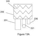
- the invention provides a stent graft (200), comprising:
- a stent graft 200 including a main body stent graft 205 defining a lumen that has a first end 207 and a second end 209.
- the first end 207 of the main body stent graft 205 may be the proximal end of the stent graft 200 configured to be positioned closer to a patient's heart than the second end 209 or distal end of the main body stent graft 205 upon deployment.
- the diaphragm 210 may be coupled to the main body stent graft 205 at a location within the lumen or at the first end 207 or the second end 209.
- the diaphragm 210 may be coupled to the main body stent graft 205 at a location ranging from the second or distal end 209 of the main body stent graft 205 up to a midsection of the main body stent graft 205.
- This arrangement may beneficially permit pressure from blood flow to act upon the proximal sidewall of the main body stent graft above the diaphragm, which may aid in sealing and fixation of the stent graft to the lumen in which it is deployed.
- the diaphragm 210 defines at least three openings.
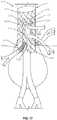
- the diaphragm 210 may define a first opening 230 coupled to a first stent graft extension 231, a second opening 235 coupled to a second stent graft extension 236, a third opening 220 coupled to a third stent graft extension 221 and a fourth opening 225 coupled to a fourth stent graft extension 226.
- the first opening 230 may be used to receive a bridging stent for placement in the infrarenal segment of the aorta or other native vessel
- the second opening 235 may be used to receive a bridging stent for placement in the celiac and SMA or other native vessel
- the third and fourth openings 220, 225 may be used to receive a bridging stent for placement in the renal arteries or other native vessel.
- the first opening 230 may be used to receive a bridging stent for placement in the aortic arch
- the second opening 235 may be used to receive a bridging stent for placement in the innominate (right common carotid artery and the right subclavian artery) or other native vessel
- the third and fourth openings 220, 225 may be used to receive a bridging stent for placement in the left common carotid artery and the left subclavian artery or other native vessel.
- the first opening 230 may have a diameter larger than a diameter of the second opening 235.
- the diameter of the second opening 235 may be larger than a diameter of the third opening 220 and a diameter of the fourth opening 225.
- the second opening 235, the third opening 220 and the fourth opening 225 may each have the same size diameter.
- the first opening 230 and the second opening 235 are defined on opposite sides of the diaphragm 210.
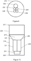
- the first opening 230, the second opening 235, the third opening 220 and the fourth opening 225 are each defined in different quadrants 211-214 of the diaphragm 210, as shown in Figure 11 .
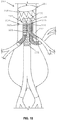
- a fifth opening 237 is defined in the diaphragm 210 and coupled to a fifth stent graft extension 238.
- the fifth opening 237 may be used to receive a bridging stent for placement in the celiac and SMA or other native vessel.
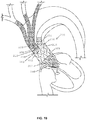
- the first opening 230 has a diameter larger than a diameter of the second opening 235 and a diameter of the fifth opening 237 (see Figures 9 , 14 and 16 ).
- the diameter of the second opening 235 and the diameter of the fifth opening 237 may be larger than a diameter of the third opening 220 and a diameter of the fourth opening 225.
- the diameter of the second opening 235 and the diameter of the fifth opening 237 may have the same dimension as a diameter of the third opening 220 and a diameter of the fourth opening 225.
- the first opening 230, the second opening 235 and the fifth opening 237 may be arranged linearly in the diaphragm 210, and the third opening 220 and the fourth opening 225 may be arranged on opposite sides of each of the first, second and fifth openings 230, 235, 237, as shown in Figure 16 .
- the third opening 220 and the fourth opening 225 may be arranged adjacent to each other and may be arranged together on a side of the diaphragm 210 opposite to the first opening 230.
- the first opening 230 may be arranged in a first quadrant 211 of the diaphragm 210
- the third opening 220 may be arranged in a second quadrant 212 of the diaphragm
- the second opening 235 and the fifth opening 237 may be arranged in a third quadrant 213 of the diaphragm
- the fourth opening 225 may be arranged in a fourth quadrant 214 of the diaphragm 210, as shown in Figure 14 .
- the diaphragm 210 is angled relative to a sidewall 218 of the main body stent graft 205 in a direction toward the second end 209 of the main body stent graft 205.
- the openings 220, 225, 230 i.e. the first opening 230, the second opening 235, the third opening 220 and the fourth opening 225 in the diaphragm 210 are defined in the center of the diaphragm 210, and the diaphragm 210 is substantially funnel-shaped.
- an end of at least one of the stent graft extensions may be tapered adjacent to the diaphragm 210, as shown and described with respect to the first aspect of the invention.
- the first end 207 of at least one of the lumens of the first stent graft extension 231, the second stent graft extension 236, the third stent graft extension 221 and the fourth stent graft extension 226 is tapered. This arrangement may aid with guidewire alignment and entry into the respective lumens of the stent graft extensions in order to place extension or bridging stents and may encourage laminar blood flow.
- the openings of the diaphragm 210 may be reinforced to mate with bridging stent grafts or extension stent grafts, for example.
- the reinforcement material may include nitinol, for example, or any nonextendible, collapsible material that is biocompatible.
- the diaphragm 210 may have an expandable frame that may be configured to apply an outward radial force to the main body stent graft 205. This frame may aid with fixation and seal with a vessel lumen.
- the diameter of the main body stent graft 205 may range from about 20 mm to about 65 mm, and preferably in the visceral segment from about 23 mm to about 40 mm or from about 28 mm to about 36 mm and preferably in the thoracic aorta from about 30 mm to about 65 mm or from about 40 mm to about 55 mm.
- the length of the main body stent graft 205 may range from about 10 mm to about 150 mm and preferably from about 20 mm to about 60 mm.
- each of the second stent graft extension 236 and the fifth stent graft extension 238 may have a length ranging from about 0.5 mm to about 40 mm, in on example. In yet another embodiment of the disclosure, each of a diameter of the second stent graft extension 236 and a diameter of the fifth stent graft extension 238 may range from about 6 mm to about 14 mm.
- the first stent graft extension 231 may have a length of at least 30 mm and may have a diameter ranging from about 8 mm to about 25 mm. In another embodiment of the disclosure, the first opening 230 may have a diameter ranging from about 8 mm to about 25 mm. In a further embodiment of the disclosure the third opening 220 and the fourth opening 225 may each have a diameter ranging from about 4 mm to about 25 mm. In another embodiment of the disclosure, the third stent graft extension 221 and the fourth stent graft extension 226 may each have a diameter ranging from about 4 mm to about 12 mm.
- the stent graft 200 may also include a plurality of sealing rings coupled to the main body stent graft 205.
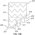
- the plurality of sealing rings may include a proximal sealing ring 245 coupled to the main body stent graft 205 at or directly adjacent to the first end 207.
- the proximal sealing ring 245 may have a bi-level construction defining an upper portion and a lower portion.
- the proximal sealing ring may be ring-shaped.
- the stent graft may include a visceral vessel opening 175 having an inverted U-shape defined in the sidewall of the main body stent graft 205 and extending from the diaphragm 210 to the second end 209 of the main body stent graft 205.
- the visceral opening may advantageously avoid blocking blood flow and permit access to the celiac and SMA arteries.
- the plurality of sealing rings may include a distal sealing ring 176 coupled to the main body stent graft 205 between the diaphragm 210 and the second end 209 of the main body stent graft 205.
- the distal sealing ring 276 may have a radial portion 277 arranged about a portion of the circumference of the main body stent graft 205 and an arch portion 278 aligned with the visceral vessel opening 275.
- each end of the radial portion 277 of the distal sealing ring 276 may transition to the arch portion 278 via two curved segments 279 each having a radius of curvature ranging from about 20 mm to about 50 mm.
- the length of the main body stent graft 205 between the first end 207 and the diaphragm 210 may range from about 10 mm to about 150 mm.
- the length of the main body stent graft 205 from the diaphragm 210 to the second end 209 of the main body stent graft 205 may range from about 0.05 mm to about 40 mm.
- a pair of opposing helical stent structures may be coupled to one or more of the first stent graft extension 231, the second stent graft extension 236, the third stent graft extension 221, the fourth stent graft extension 226 and the fifth stent graft extension 238.
- the first end 207 of the main body stent graft 205 may be coupled to a fixation stent, as described below with respect to the second aspect of the invention.
- the stent graft may include a stent valve 280 affixed to the first end 207 of the main body stent graft 205.
- a free end of the stent valve may be covered and a portion of the stent valve extending between the free end and the main body stent graft 205 may be uncovered.
- a "stent valve" is a percutaneous self-expanding valve affixed to a proximal or first end 207 of the main body stent graft 205 with the uncovered portion overlaying the coronary arteries to maintain blood flow.
- An exemplary embodiment of the disclosure of the stent valve includes the Corevalve® manufactured by Medtronic.
- the free end of the stent valve may be covered with an impervious natural or synthetic material.
- the stent valve may be placed in the outflow tract of the aortic valve.
- the stent valve's anchoring mechanism is derived from, for example, a funnel shape with a larger diameter at the free end and smaller diameter at the point where the covered portion meets the uncovered portion.
- the stent graft provides:
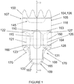
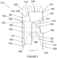
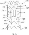
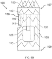
- a stent graft 100 including a main body stent graft 105 defining a lumen having an inlet 106 defined at a first or proximal end 107 of the main body stent graft 105 and having an outlet 108 defined at a second or distal end 109 of the main body stent graft 105.
- a portion of the lumen of the main body stent graft 105 arranged between the diaphragm 110 and the proximal end 107 of the main body stent graft 105 may have a diameter ranging from about 20 mm to about 65 mm and preferably from about 20 mm to about 46 mm.
- the main body stent graft 105 may have a length ranging from about 10 mm to about 150 mm extending between the first end 107 of the main body stent graft 105 and the first end 116 of the visceral-vessel opening 115. In a further embodiment of the disclosure, the main body stent graft 105 may have a length ranging from 0 mm to about 40 mm extending between the second or distal end 117 of the visceral-vessel opening 115 and the second end 109 of the main body stent graft 105.
- the stent graft 100 includes a diaphragm 110 disposed within the lumen of the main body stent graft 105 and coupled to the main body stent graft 105.
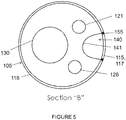
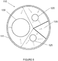
- the diaphragm 110 defines a first opening 130, a second opening 135, a third opening 120 and a fourth opening 125.
- the first opening 130 may be used to stent the infrarenal segment
- the second opening 135 may be used stent the celiac and SMA arteries
- the third opening 120 and the fourth opening 125 may be used to stent the renal arteries.
- the second opening 135 may be aligned in a quadrant of the diaphragm 110 that lies above the visceral-vessel opening 115, discussed in more detail below, and the first opening 130 and the third and fourth openings 120, 125 may be arranged in various configurations in the same or other quadrants of the diaphragm 110.
- the first opening 130 and the second opening 135 may be arranged on opposite sides of the diaphragm 110 with the third opening 120 and the fourth opening 125 likewise arranged on opposite sides of the diaphragm 110 between the first opening 130 and the second opening 135.
- the third and fourth openings 120, 125 may be arranged on the same side of the diaphragm 110 between the first opening 130 and the second opening 135.
- the first opening 130 and one of the third and fourth openings 120, 125 and may be arranged on opposite sides of the diaphragm 110 with the other opening arranged there between.
- the first opening 130 and the third and fourth openings 120, 125 may be arranged such that there is no other inlet directly opposite the second opening 135.
- the diaphragm 110 may be sloped or tapered in the regions surrounding these various openings.
- the second opening 135 may be defined as a V-shape, a half-circle having a radius ranging from about 5 mm to about 15 mm or a complete circular opening with a diameter ranging from about 6 mm to about 20 mm, among other possibilities.
- the third opening 120, fourth opening 125, first opening 130 may have a substantially circular shape.
- three stent graft extensions 121, 126 and 131 may be directly coupled to the third opening 120, the fourth opening 125 and the first opening 130, respectively, in fluid-tight (blood-tight) manner prior to deployment of the stent graft 100.
- These stent graft extensions 121, 126, 131 each define a lumen and are configured to receive extension or bridging stent grafts that may be held in place via passive or active fixation.
- This arrangement may provide blood flow between the stent graft 100 and the renal arteries and or may provide blood flow to the infrarenal arteries including, for example, the aorta and the common iliac arteries.
- the stent graft extensions 121, 126, 131 may be straight or gradually sweeping and their distal free ends 123, 128, 133 may be freely movable to place bridging stent grafts.
- the stent graft extension 131 coupled to the first opening 130 may have a length of at least 30 mm and, in another embodiment of the disclosure, may have a length that ranges from about 10 mm to 120 mm.
- the stent graft extension 131 may have a diameter ranging from about 8 mm to about 25 mm.
- the first opening 130 may have a diameter ranging from about 8 mm to about 25 mm.
- the diameter of the first opening 130 may be larger than the diameter of the stent graft extension 131 coupled thereto such that a first or proximal end of the stent graft extension 131 is tapered 132.
- the third and fourth openings 120, 125 may each have a diameter ranging from about 4 mm to about 25 mm.
- the stent graft extensions 121, 126 coupled to the third and fourth openings may each have a diameter ranging from about 4 mm to about 18 mm.
- the diameter of each of the third and fourth openings 120, 125 may be larger than the diameter of each of the stent graft extensions 121, 126 coupled thereto such that a first or proximal end of each of the stent graft extensions 121, 126 is tapered 122, 127. Tapering from the diaphragm openings to the various stent graft extensions may aid with guidewire alignment and entry into the respective lumens to place extension or bridging stents and may encourage laminar blood flow.
- the stent graft extensions 121, 126 and 131 may be placed separately after deployment.
- the stent graft extensions 121, 126, 131 may have flared proximal ends that are arranged proximal of the diaphragm upon deployment.
- a pair of opposing helical stent structures may be coupled to and extend along the length of one or more of the stent graft extensions 121, 126 and 131.
- the helical stent structures may advantageously prevent elongation of the lumens.
- These helical stent structures may be made from biocompatible materials with elastic shape memory, such as nitinol, stainless steel, plastics, polymers or any combination of such materials, among other possibilities.
- the diaphragm 110 may have an expandable frame 111.
- This expandable frame 111 may be configured to apply an outward radial force to the main body stent graft 105 in response to a downward force applied to the diaphragm 110.
- the downward force may be due to blood flow, for example.
- the diaphragm 110 may be positioned within the lumen of the main body stent graft 105 at or between a first end 116 of the visceral-vessel opening 115 and a second end 117 of the visceral-vessel opening 115.
- the stent graft 100 also includes a visceral-vessel opening 115 defined in a sidewall 118 of the main body stent graft 105 between the first end 107 and the second end 109 of the main body stent graft 105.
- the visceral-vessel opening 115 may have a height ranging from about 10 mm to about 60 mm and may have a width ranging from about 5 mm to about 30 mm.
- the visceral-vessel opening may be wider at a first or proximal end than at a second or distal end, which may provide more graft surface area between the visceral-vessel opening 115 and two renal openings 170 to provide a more robust seal between the stent graft and vasculature.
- the visceral-vessel opening 115 may be covered with a flow-diverting material, for example, a high pick density braided or woven self-expanding stent material.
- This flow-diverting material may allow patency to the visceral vessels, for example, while minimizing the degree of unstented aortic wall to aid in anchoring and seal between the pararenal stent graft within vasculature. This may provide a more robust seal between the stent graft and aorta.
- the flow-diverting material may also permit formation of thrombus and arterial development therethrough, which may aid in appropriate blood flow and blood pressure through this region of the main body stent graft 105.
- the stent graft 100 includes a visceral chamber 140 defined by a sidewall 141 coupled to one of the diaphragm 110 and the second opening 135 and to one of the sidewall of the main bode stent graft and the visceral-vessel opening.
- the visceral chamber 140 may provide blood flow to the SMA and celiac arteries.
- a surgeon may utilize the visceral chamber 140 to place bridging stents in the SMA and/or celiac arteries
- the stent graft 100 may further include a plurality of sealing rings coupled to the main body stent graft 105.
- the plurality of sealing rings may include a proximal sealing ring 145 coupled to the main body stent graft 105 at or directly adjacent to the first end 107 of the main body stent graft 105.
- the proximal sealing ring 145 may have a bi-level construction defining an upper portion 146 and a lower portion 147.
- the lower portion 147 of the proximal sealing ring 145 may be aligned with and arranged proximal to the visceral-vessel opening 115, and the lower portion 147 may be arranged distal to the upper portion 146 of the proximal sealing ring 145.
- the upper portion 146 of the proximal sealing ring 145 may be longitudinally spaced apart from the lower portion 147 along the main body stent graft 105 by a distance ranging from about 0 mm to about 40 mm.
- a peripheral edge 104 of the first end 107 of the main body stent graft 105 may have the same bi-level contour as the proximal sealing ring 145.
- the main body stent graft 105 may have a length ranging from about 0 mm to about 20 mm extending between the lower portion 147 of the proximal sealing ring 145 of the main body stent graft 105 and the first end 116 of the visceral-vessel opening 115.
- the graft material of the main body stent graft 105 may have the same boundary as the proximal sealing ring 145 to avoid covering the lumbar arteries that deliver blood to the spine.
- the graft material may have a uniform circumference along the upper boundary of the proximal sealing ring 145.
- the graft material may extend beyond the upper proximal boundary of the proximal sealing ring 145 to the top or proximal edge of a fixation stent 150.
- the plurality of sealing rings may include a visceral-vessel sealing ring 155 coupled to the main body stent graft 105 such that the visceral-vessel sealing ring 155 surrounds the visceral-vessel opening 115.
- the visceral-vessel sealing ring 155 may apply a circumferential force to keep the visceral-vessel opening 115 intact upon deployment providing a fluid tight seal about the SMA and celiac arteries.
- the plurality of sealing rings may also include at least one support sealing ring 160 coupled to the main body stent graft 105 such that a first end 161 of the at least one support sealing ring 160 is coupled to a first side of the visceral-vessel sealing ring 155 and a second end 162 of the at least one support sealing ring 155 is coupled to a second side of the visceral-vessel sealing ring 155.
- the visceral-vessel sealing ring 155 may also work in combination with the support sealing ring 160 to provide a circumferential radial force relative to the main body stent graft 105 to provide a fluid tight (i.e., blood-tight) seal with the aorta, for example.
- the at least one support sealing ring 160 may include a proximal support sealing ring 163, a distal support sealing ring 164 and a central support sealing ring 160.
- the central support sealing ring 160 may be coupled to the visceral vessel sealing ring 155.
- the proximal support sealing ring 163 may be coupled to the main body stent graft 105 between the first end 107 of the main body stent graft 105 and the central support sealing ring 160.
- the distal support sealing ring 164 may be coupled to the main body stent graft 105 between the second end 109 of the main body stent graft 105 and the central support sealing ring 160.
- the plurality of sealing rings may include a distal sealing ring 165 coupled to the main body stent graft 105 at or directly adjacent to the second end 109 of the main body stent graft 105.
- two renal openings 170 may be defined in the sidewall 118 of the main body stent graft 105 distal to the diaphragm 110.
- the distal sealing ring 165 may have two radial portions 166 joined by two arch portions 167.
- the two arch portions 167 may be arranged longitudinally along the sidewall 118 of the main body stent graft 105 and the two radial portions 166 are arranged about the circumference of the main body stent graft 105.
- the two arch portions 167 are aligned with the two renal openings 170.
- an effective diameter extending between the two radial portions 166 of the distal sealing ring 165 may range from about 20 mm to about 50 mm.
- the two arch portions 167 may have a width ranging from about 4 mm to about 30 mm.
- the length of the main body stent graft 105 may be shortened to permit the renal stent grafts to exit from the second end 109 such that they are able to have a gentle sweep or large radius of curvature from the renal inlet and the target vessel ostium when bridging stents are placed.
- the two renal openings 170 in the sidewall of the main body stent graft may be fenestrations sized and shaped to allow access to the native arteries.
- a bridging stent graft may comprise spaced-apart stent rings coupled to two wires longitudinally disposed along the length of and on opposite sides of the bridging stent graft in a helical shape. This arrangement may beneficially prevent elongation of the bridging stent graft.
- An appropriate overlap with the stent graft extensions 121, 126 coupled to the third and fourth openings 120, 125 or stent graft extension 131 coupled to the first opening 130 may be adequate to achieve passive fixation with a bridging stent graft during stent graft debranching procedures. The length of this overlap region may be less if active fixation features are also employed with the stent grafts, for example.
- the stent graft provides:
- a stent graft 100 including a main body stent graft 105 defining a lumen having first end 107 and a second 109 that may correspond to a proximal end and a distal end, respectively, in one embodiment of the disclosure.
- a visceral-vessel opening 115 is defined in a sidewall of the main body stent graft 105 between the first end 107 and the second end 109 of the main body stent graft 105.
- a diaphragm 110 is disposed within the lumen of the main body stent graft 105 and coupled to the main body stent graft 105.
- the diaphragm defines a first opening, a second opening, a third opening and a fourth opening.
- each of the openings may receive a bridging stent, for example, and couple the infrarenal segment to the first opening 130, couple the celiac and SMA arteries to the second opening 135 and couple the couple the renal arteries to the third and fourth openings 120, 125.
- a visceral chamber 140 may be defined by the diaphragm 110, the sidewall of the main body stent graft 105 and a visceral sidewall 141 extending between the diaphragm 110 and the sidewall of the main body stent graft 105.
- a fifth opening 137 is defined in the diaphragm between the visceral sidewall and the sidewall of the main body stent graft 105. This fifth opening 137 may beneficially permit blood flow to the celiac and SMA arteries while the second opening 135 is being actively stented or otherwise blocked and vice versa.
- the fifth opening 137 may also allow for more than one of the celiac and SMA arteries to be bridged with stents grafts.
- the second and fifth openings 135, 137 are defined in the diaphragm 110 between the visceral sidewall 141 and the sidewall of the main body stent graft 105.
- the visceral sidewall 141 surrounds a portion of the visceral-vessel opening 115 defined between the second end 109 of the main body stent graft 105 and the diaphragm 110.
- the second opening 135 and the fifth opening 137 may be arranged adjacent to each other.
- the second opening 135 may be coupled to a stent graft extension 136 defining a lumen
- the fifth opening 137 may also be coupled to a stent graft extension 138 defining a lumen.
- each of the stent graft extensions coupled to one of the second and fifth openings may have a diameter ranging from about 6 mm to about 14 mm and may have a length ranging from about 0.5 mm to about 40 mm.
- one or more of the first 130, second 135, third 120, fourth 125 and fifth 137 openings may be reinforced.
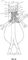
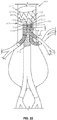
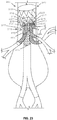
- the stent graft 300 includes a plurality of anchors 385 that each define an eyelet.
- the plurality of anchors 385 are arranged longitudinally at intervals along the main body stent graft 305.
- the stent graft 300 includes a string 386 having a first end 387 and a second end 388.
- the string 386 may be slidably disposed through the eyelets of the plurality of anchors 385 such that the main body stent graft 305 has a partially-expanded condition and a fully-expanded condition.
- the string 386 may be under tension and the first end 387 of the string may be fixedly coupled to a first anchor 390 of the plurality anchors 385 and the second end 388 of the string 386 may be releasably coupled to a second anchor 391 of the plurality of anchors.
- the second end of the string 388 may be released from the second anchor 391 and the string 386 may be untensioned.
- the main body stent graft 305 may expand from 50% to 95% of the fully-expanded diameter in the partially-expanded condition.
- the partially-expanded condition may enable the stent graft to be deployed into a lumen and then subsequently repositioned.
- the smaller diameter of the partially-expanded stent graft may permit the stent graft to be moved proximally and distally to the desired location in the lumen and rotated for alignment with appropriate branch vasculature.
- the releasable end 388 of the string 386 may be decoupled from an anchor 391, as described below, and the stent graft 300 may transition into the fully-expanded condition due to shape memory of stents or balloon expansion, for example.
- the plurality of anchors may be arranged on a side of the main body stent graft opposite to a visceral-vessel opening. In a further embodiment of the disclosure, the plurality of anchors may be arranged as laterally opposed pairs (see Figure 24 ). In another embodiment of the disclosure, the plurality of anchors may be arranged in a zig-zag pattern.
- the eyelets of the plurality of anchors 385 and the string 386 may be made of a low-friction material to enable the stent graft 300 to transition from the partially-expanded condition to the fully-expanded condition.
- the stent grafts of the present disclosure may contain any further suitable components, including but not limited to radiopaque markers to aid in visualization and to facilitate accurate placement of the stent graft.
- radiopaque markers may take the form of gold bands at the distal end of each individual lumen of a given stent graft or a directional marker, for example in the shape of an "S" or any other suitable form for indicating direction and orientation of the stent graft.
- the first or proximal end 107, 207 of the main body stent graft 105 may be coupled to a fixation stent 150.
- bi-directional anchoring hooks may be formed as part of the fixation stent 150 may be utilized to gain solid purchase in the non-diseased portion of a vessel wall.
- This fixation stent 150 may provide for radial-force fixation within the vessel in conjunction with bidirectional hooks.
- the fixation stent 150 may be biased away from the lumen of the main body stent graft 105 to maintain fixation with vasculature in a deployed condition even if an aneurysm advances proximally.
- the disclosure provides a method for placement of the stent graft 100 according to the first aspect of the invention.
- the method includes (a) introducing a guidewire into any appropriately sized arterial configuration via arterial access, (b) loading a delivery catheter containing the stent graft of any of the foregoing disclosed embodiments onto the guidewire, (c) moving the delivery catheter along the guidewire and introducing the delivery catheter into the appropriately sized arterial configuration via arterial access and (d) deploying the stent graft into the appropriately sized arterial configuration and/or a lumen of a previously-placed stent graft.
- the method may further include maintaining the stent graft in a partially-compressed condition via a tensioned string disposed through a plurality of anchors that each define an eyelet.
- the tension on the string may be reduced by releasing one end of the wire from a first anchor of the plurality of anchors. Once tension on the string is reduced, the stent graft may then expand into the fully-expanded condition.
- the second aspect may further include (e) loading a second delivery catheter containing a bridging stent graft onto the guidewire, (f) moving the second delivery catheter along the guidewire and introducing the second delivery catheter into the proximal end 107 of main body lumen of the stent graft 105 via arterial access, (g) selecting from among the first renal inlet 120, the second renal inlet 125, the infrarenal inlet 130 or the visceral inlet 135 defined in the diaphragm 110, (h) introducing the second delivery catheter into the selected inlet and into either a lumen 121, 126, 131 coupled to the selected inlet or an appropriately sized arterial lumen and (i) deploying all or a portion of the bridging stent graft into the selected inlet or the appropriately sized arterial lumen.
Landscapes
- Health & Medical Sciences (AREA)
- Engineering & Computer Science (AREA)
- Biomedical Technology (AREA)
- Cardiology (AREA)
- Oral & Maxillofacial Surgery (AREA)
- Transplantation (AREA)
- Heart & Thoracic Surgery (AREA)
- Vascular Medicine (AREA)
- Life Sciences & Earth Sciences (AREA)
- Animal Behavior & Ethology (AREA)
- General Health & Medical Sciences (AREA)
- Public Health (AREA)
- Veterinary Medicine (AREA)
- Gastroenterology & Hepatology (AREA)
- Pulmonology (AREA)
- Prostheses (AREA)
Applications Claiming Priority (6)
| Application Number | Priority Date | Filing Date | Title |
|---|---|---|---|
| US201461932280P | 2014-01-28 | 2014-01-28 | |
| US14/311,733 US8998971B1 (en) | 2014-01-28 | 2014-06-23 | Pararenal stent graft and methods for use |
| US2014043651 | 2014-06-23 | ||
| US201462067808P | 2014-10-23 | 2014-10-23 | |
| US201562104053P | 2015-01-15 | 2015-01-15 | |
| PCT/US2015/013344 WO2015116715A1 (en) | 2014-01-28 | 2015-01-28 | Pararenal and thoracic arch stent graft and methods for use |
Publications (3)
| Publication Number | Publication Date |
|---|---|
| EP3099270A1 EP3099270A1 (en) | 2016-12-07 |
| EP3099270A4 EP3099270A4 (en) | 2017-08-09 |
| EP3099270B1 true EP3099270B1 (en) | 2021-05-05 |
Family
ID=53757696
Family Applications (1)
| Application Number | Title | Priority Date | Filing Date |
|---|---|---|---|
| EP15743077.8A Active EP3099270B1 (en) | 2014-01-28 | 2015-01-28 | Pararenal and thoracic arch stent graft |
Country Status (7)
Cited By (15)
| Publication number | Priority date | Publication date | Assignee | Title |
|---|---|---|---|---|
| US11311376B2 (en) | 2019-06-20 | 2022-04-26 | Neovase Tiara Inc. | Low profile prosthetic mitral valve |
| US11357622B2 (en) | 2016-01-29 | 2022-06-14 | Neovase Tiara Inc. | Prosthetic valve for avoiding obstruction of outflow |
| US11389291B2 (en) | 2013-04-04 | 2022-07-19 | Neovase Tiara Inc. | Methods and apparatus for delivering a prosthetic valve to a beating heart |
| US11389294B2 (en) | 2012-05-30 | 2022-07-19 | Neovasc Tiara Inc. | Methods and apparatus for loading a prosthesis onto a delivery system |
| US11413139B2 (en) | 2011-11-23 | 2022-08-16 | Neovasc Tiara Inc. | Sequentially deployed transcatheter mitral valve prosthesis |
| US11419720B2 (en) | 2010-05-05 | 2022-08-23 | Neovasc Tiara Inc. | Transcatheter mitral valve prosthesis |
| US11464631B2 (en) | 2016-11-21 | 2022-10-11 | Neovasc Tiara Inc. | Methods and systems for rapid retraction of a transcatheter heart valve delivery system |
| US11491006B2 (en) | 2019-04-10 | 2022-11-08 | Neovasc Tiara Inc. | Prosthetic valve with natural blood flow |
| US11497602B2 (en) | 2012-02-14 | 2022-11-15 | Neovasc Tiara Inc. | Methods and apparatus for engaging a valve prosthesis with tissue |
| US11602429B2 (en) | 2019-04-01 | 2023-03-14 | Neovasc Tiara Inc. | Controllably deployable prosthetic valve |
| US11737872B2 (en) | 2018-11-08 | 2023-08-29 | Neovasc Tiara Inc. | Ventricular deployment of a transcatheter mitral valve prosthesis |
| US11779742B2 (en) | 2019-05-20 | 2023-10-10 | Neovasc Tiara Inc. | Introducer with hemostasis mechanism |
| US11793640B2 (en) | 2017-08-25 | 2023-10-24 | Neovasc Tiara Inc. | Sequentially deployed transcatheter mitral valve prosthesis |
| US11998447B2 (en) | 2019-03-08 | 2024-06-04 | Neovasc Tiara Inc. | Retrievable prosthesis delivery system |
| US12109111B2 (en) | 2015-12-15 | 2024-10-08 | Neovasc Tiara Inc. | Transseptal delivery system |
Families Citing this family (12)
| Publication number | Priority date | Publication date | Assignee | Title |
|---|---|---|---|---|
| CN106420107B (zh) | 2011-11-16 | 2019-02-05 | 波顿医疗公司 | 用于主动脉分支血管的修复的装置和方法 |
| US8998971B1 (en) | 2014-01-28 | 2015-04-07 | Sanford Health | Pararenal stent graft and methods for use |
| US9980832B2 (en) | 2014-01-28 | 2018-05-29 | Sanford Health | Pararenal and thoracic arch stent graft and methods for use |
| JP2017528256A (ja) | 2014-09-23 | 2017-09-28 | ボルトン メディカル インコーポレイテッド | 血管修復デバイスおよび使用方法 |
| US10405965B2 (en) | 2015-03-25 | 2019-09-10 | Sanford Health | Pararenal and thoracic arch stent graft and methods for use |
| JP7007294B2 (ja) | 2016-04-05 | 2022-01-24 | ボルトン メディカル インコーポレイテッド | 内部トンネルおよび開窓を有するステントグラフト |
| US20170340462A1 (en) | 2016-05-25 | 2017-11-30 | Bolton Medical, Inc. | Stent grafts and methods of use for treating aneurysms |
| WO2019101077A1 (zh) * | 2017-11-24 | 2019-05-31 | 杭州唯强医疗科技有限公司 | 增强稳定性的血管分流架及血管支架 |
| CN109833124B (zh) | 2017-11-24 | 2024-07-19 | 杭州唯强医疗科技有限公司 | 改进显影可视性的血管分流架及血管支架 |
| CN209678753U (zh) | 2017-11-24 | 2019-11-26 | 杭州唯强医疗科技有限公司 | 多腔覆膜支架 |
| KR102518171B1 (ko) * | 2020-11-23 | 2023-04-04 | 연세대학교 산학협력단 | 한 쌍의 스텐트 그라프트가 삽입결합되는 메인바디를 갖는 스텐트 그라프트 결합구조체 |
| US11324583B1 (en) | 2021-07-06 | 2022-05-10 | Archo Medical LTDA | Multi-lumen stent-graft and related surgical methods |
Family Cites Families (7)
| Publication number | Priority date | Publication date | Assignee | Title |
|---|---|---|---|---|
| US6325819B1 (en) * | 1996-08-19 | 2001-12-04 | Cook Incorporated | Endovascular prosthetic device, an endovascular graft prothesis with such a device, and a method for repairing an abdominal aortic aneurysm |
| US6450535B1 (en) * | 1999-05-07 | 2002-09-17 | R. R. Donnelley & Sons Company | Book for holding products such as compact discs and method of making the same |
| US6585756B1 (en) * | 1999-05-14 | 2003-07-01 | Ernst P. Strecker | Implantable lumen prosthesis |
| US7314483B2 (en) * | 2000-11-16 | 2008-01-01 | Cordis Corp. | Stent graft with branch leg |
| US6942692B2 (en) * | 2000-11-16 | 2005-09-13 | Cordis Corporation | Supra-renal prosthesis and renal artery bypass |
| WO2005032340A2 (en) * | 2003-09-29 | 2005-04-14 | Secant Medical, Llc | Integral support stent graft assembly |
| US7828837B2 (en) * | 2005-02-17 | 2010-11-09 | Khoury Medical Devices, LLC. | Vascular endograft |
-
2015
- 2015-01-28 AU AU2015211083A patent/AU2015211083B2/en not_active Expired - Fee Related
- 2015-01-28 WO PCT/US2015/013344 patent/WO2015116715A1/en active Application Filing
- 2015-01-28 CN CN201580011211.8A patent/CN106456314A/zh active Pending
- 2015-01-28 JP JP2016548115A patent/JP6499186B2/ja active Active
- 2015-01-28 CA CA2937794A patent/CA2937794A1/en not_active Abandoned
- 2015-01-28 EP EP15743077.8A patent/EP3099270B1/en active Active
- 2015-01-28 BR BR112016017351A patent/BR112016017351A2/pt not_active Application Discontinuation
Cited By (22)
| Publication number | Priority date | Publication date | Assignee | Title |
|---|---|---|---|---|
| US11419720B2 (en) | 2010-05-05 | 2022-08-23 | Neovasc Tiara Inc. | Transcatheter mitral valve prosthesis |
| US12053369B2 (en) | 2011-11-23 | 2024-08-06 | Neovasc Tiara Inc. | Sequentially deployed transcatheter mitral valve prosthesis |
| US11413139B2 (en) | 2011-11-23 | 2022-08-16 | Neovasc Tiara Inc. | Sequentially deployed transcatheter mitral valve prosthesis |
| US12138159B2 (en) | 2012-02-14 | 2024-11-12 | Neovasc Tiara Inc. | Methods and apparatus for engaging a valve prosthesis with tissue |
| US11497602B2 (en) | 2012-02-14 | 2022-11-15 | Neovasc Tiara Inc. | Methods and apparatus for engaging a valve prosthesis with tissue |
| US11617650B2 (en) | 2012-05-30 | 2023-04-04 | Neovasc Tiara Inc. | Methods and apparatus for loading a prosthesis onto a delivery system |
| US11389294B2 (en) | 2012-05-30 | 2022-07-19 | Neovasc Tiara Inc. | Methods and apparatus for loading a prosthesis onto a delivery system |
| US11389291B2 (en) | 2013-04-04 | 2022-07-19 | Neovase Tiara Inc. | Methods and apparatus for delivering a prosthetic valve to a beating heart |
| US12109111B2 (en) | 2015-12-15 | 2024-10-08 | Neovasc Tiara Inc. | Transseptal delivery system |
| US11357622B2 (en) | 2016-01-29 | 2022-06-14 | Neovase Tiara Inc. | Prosthetic valve for avoiding obstruction of outflow |
| US12193932B2 (en) | 2016-01-29 | 2025-01-14 | Neovasc Tiara Inc. | Prosthetic valve for avoiding obstruction of outflow |
| US11464631B2 (en) | 2016-11-21 | 2022-10-11 | Neovasc Tiara Inc. | Methods and systems for rapid retraction of a transcatheter heart valve delivery system |
| US12201524B2 (en) | 2016-11-21 | 2025-01-21 | Neovasc Tiara Inc. | Methods and systems for rapid retraction of a transcatheter heart valve delivery system |
| US11793640B2 (en) | 2017-08-25 | 2023-10-24 | Neovasc Tiara Inc. | Sequentially deployed transcatheter mitral valve prosthesis |
| US11737872B2 (en) | 2018-11-08 | 2023-08-29 | Neovasc Tiara Inc. | Ventricular deployment of a transcatheter mitral valve prosthesis |
| US11998447B2 (en) | 2019-03-08 | 2024-06-04 | Neovasc Tiara Inc. | Retrievable prosthesis delivery system |
| US11602429B2 (en) | 2019-04-01 | 2023-03-14 | Neovasc Tiara Inc. | Controllably deployable prosthetic valve |
| US12036117B2 (en) | 2019-04-10 | 2024-07-16 | Neovasc Tiara Inc. | Prosthetic valve with natural blood flow |
| US11491006B2 (en) | 2019-04-10 | 2022-11-08 | Neovasc Tiara Inc. | Prosthetic valve with natural blood flow |
| US11779742B2 (en) | 2019-05-20 | 2023-10-10 | Neovasc Tiara Inc. | Introducer with hemostasis mechanism |
| US11311376B2 (en) | 2019-06-20 | 2022-04-26 | Neovase Tiara Inc. | Low profile prosthetic mitral valve |
| US11931254B2 (en) | 2019-06-20 | 2024-03-19 | Neovasc Tiara Inc. | Low profile prosthetic mitral valve |
Also Published As
| Publication number | Publication date |
|---|---|
| EP3099270A4 (en) | 2017-08-09 |
| BR112016017351A2 (pt) | 2017-08-08 |
| JP2017503607A (ja) | 2017-02-02 |
| CN106456314A (zh) | 2017-02-22 |
| AU2015211083B2 (en) | 2019-11-07 |
| WO2015116715A1 (en) | 2015-08-06 |
| EP3099270A1 (en) | 2016-12-07 |
| JP6499186B2 (ja) | 2019-04-10 |
| AU2015211083A1 (en) | 2016-08-11 |
| CA2937794A1 (en) | 2015-08-06 |
Similar Documents
| Publication | Publication Date | Title |
|---|---|---|
| US11872120B2 (en) | Pararenal and thoracic arch stent graft and methods for use | |
| EP3099270B1 (en) | Pararenal and thoracic arch stent graft | |
| US9463102B2 (en) | Pararenal and thoracic arch stent graft and methods for use | |
| US12133793B2 (en) | Endoluminal prosthesis having multiple branches or fenestrations and methods of deployment | |
| US8998971B1 (en) | Pararenal stent graft and methods for use | |
| EP2606853B1 (en) | Hybrid aortic arch replacement | |
| WO2010120417A1 (en) | Prosthesis for antegrade deployment | |
| US20170014248A1 (en) | Bridging Stent Graft with Combination Balloon Expandable and Self-Expandable Stents and Methods for Use | |
| US20170056152A1 (en) | Pre-Curved Stent Graft and Methods for Use |
Legal Events
| Date | Code | Title | Description |
|---|---|---|---|
| PUAI | Public reference made under article 153(3) epc to a published international application that has entered the european phase |
Free format text: ORIGINAL CODE: 0009012 |
|
| STAA | Information on the status of an ep patent application or granted ep patent |
Free format text: STATUS: REQUEST FOR EXAMINATION WAS MADE |
|
| 17P | Request for examination filed |
Effective date: 20160810 |
|
| AK | Designated contracting states |
Kind code of ref document: A1 Designated state(s): AL AT BE BG CH CY CZ DE DK EE ES FI FR GB GR HR HU IE IS IT LI LT LU LV MC MK MT NL NO PL PT RO RS SE SI SK SM TR |
|
| AX | Request for extension of the european patent |
Extension state: BA ME |
|
| DAX | Request for extension of the european patent (deleted) | ||
| A4 | Supplementary search report drawn up and despatched |
Effective date: 20170706 |
|
| RIC1 | Information provided on ipc code assigned before grant |
Ipc: A61F 2/88 20060101ALN20170630BHEP Ipc: A61F 2/07 20130101AFI20170630BHEP Ipc: A61F 2/852 20130101ALN20170630BHEP Ipc: A61F 2/848 20130101ALN20170630BHEP |
|
| REG | Reference to a national code |
Ref country code: HK Ref legal event code: DE Ref document number: 1231363 Country of ref document: HK |
|
| STAA | Information on the status of an ep patent application or granted ep patent |
Free format text: STATUS: EXAMINATION IS IN PROGRESS |
|
| 17Q | First examination report despatched |
Effective date: 20200617 |
|
| RIC1 | Information provided on ipc code assigned before grant |
Ipc: A61F 2/07 20130101AFI20201103BHEP Ipc: A61F 2/848 20130101ALN20201103BHEP Ipc: A61F 2/88 20060101ALN20201103BHEP Ipc: A61F 2/24 20060101ALN20201103BHEP Ipc: A61F 2/852 20130101ALN20201103BHEP |
|
| GRAP | Despatch of communication of intention to grant a patent |
Free format text: ORIGINAL CODE: EPIDOSNIGR1 |
|
| STAA | Information on the status of an ep patent application or granted ep patent |
Free format text: STATUS: GRANT OF PATENT IS INTENDED |
|
| INTG | Intention to grant announced |
Effective date: 20201223 |
|
| GRAS | Grant fee paid |
Free format text: ORIGINAL CODE: EPIDOSNIGR3 |
|
| GRAA | (expected) grant |
Free format text: ORIGINAL CODE: 0009210 |
|
| STAA | Information on the status of an ep patent application or granted ep patent |
Free format text: STATUS: THE PATENT HAS BEEN GRANTED |
|
| AK | Designated contracting states |
Kind code of ref document: B1 Designated state(s): AL AT BE BG CH CY CZ DE DK EE ES FI FR GB GR HR HU IE IS IT LI LT LU LV MC MK MT NL NO PL PT RO RS SE SI SK SM TR |
|
| REG | Reference to a national code |
Ref country code: GB Ref legal event code: FG4D |
|
| REG | Reference to a national code |
Ref country code: CH Ref legal event code: EP |
|
| REG | Reference to a national code |
Ref country code: AT Ref legal event code: REF Ref document number: 1388855 Country of ref document: AT Kind code of ref document: T Effective date: 20210515 |
|
| REG | Reference to a national code |
Ref country code: IE Ref legal event code: FG4D |
|
| REG | Reference to a national code |
Ref country code: DE Ref legal event code: R096 Ref document number: 602015068960 Country of ref document: DE |
|
| REG | Reference to a national code |
Ref country code: LT Ref legal event code: MG9D |
|
| REG | Reference to a national code |
Ref country code: AT Ref legal event code: MK05 Ref document number: 1388855 Country of ref document: AT Kind code of ref document: T Effective date: 20210505 |
|
| PG25 | Lapsed in a contracting state [announced via postgrant information from national office to epo] |
Ref country code: BG Free format text: LAPSE BECAUSE OF FAILURE TO SUBMIT A TRANSLATION OF THE DESCRIPTION OR TO PAY THE FEE WITHIN THE PRESCRIBED TIME-LIMIT Effective date: 20210805 Ref country code: AT Free format text: LAPSE BECAUSE OF FAILURE TO SUBMIT A TRANSLATION OF THE DESCRIPTION OR TO PAY THE FEE WITHIN THE PRESCRIBED TIME-LIMIT Effective date: 20210505 Ref country code: HR Free format text: LAPSE BECAUSE OF FAILURE TO SUBMIT A TRANSLATION OF THE DESCRIPTION OR TO PAY THE FEE WITHIN THE PRESCRIBED TIME-LIMIT Effective date: 20210505 Ref country code: LT Free format text: LAPSE BECAUSE OF FAILURE TO SUBMIT A TRANSLATION OF THE DESCRIPTION OR TO PAY THE FEE WITHIN THE PRESCRIBED TIME-LIMIT Effective date: 20210505 Ref country code: FI Free format text: LAPSE BECAUSE OF FAILURE TO SUBMIT A TRANSLATION OF THE DESCRIPTION OR TO PAY THE FEE WITHIN THE PRESCRIBED TIME-LIMIT Effective date: 20210505 |
|
| PG25 | Lapsed in a contracting state [announced via postgrant information from national office to epo] |
Ref country code: RS Free format text: LAPSE BECAUSE OF FAILURE TO SUBMIT A TRANSLATION OF THE DESCRIPTION OR TO PAY THE FEE WITHIN THE PRESCRIBED TIME-LIMIT Effective date: 20210505 Ref country code: SE Free format text: LAPSE BECAUSE OF FAILURE TO SUBMIT A TRANSLATION OF THE DESCRIPTION OR TO PAY THE FEE WITHIN THE PRESCRIBED TIME-LIMIT Effective date: 20210505 Ref country code: PT Free format text: LAPSE BECAUSE OF FAILURE TO SUBMIT A TRANSLATION OF THE DESCRIPTION OR TO PAY THE FEE WITHIN THE PRESCRIBED TIME-LIMIT Effective date: 20210906 Ref country code: PL Free format text: LAPSE BECAUSE OF FAILURE TO SUBMIT A TRANSLATION OF THE DESCRIPTION OR TO PAY THE FEE WITHIN THE PRESCRIBED TIME-LIMIT Effective date: 20210505 Ref country code: NO Free format text: LAPSE BECAUSE OF FAILURE TO SUBMIT A TRANSLATION OF THE DESCRIPTION OR TO PAY THE FEE WITHIN THE PRESCRIBED TIME-LIMIT Effective date: 20210805 Ref country code: ES Free format text: LAPSE BECAUSE OF FAILURE TO SUBMIT A TRANSLATION OF THE DESCRIPTION OR TO PAY THE FEE WITHIN THE PRESCRIBED TIME-LIMIT Effective date: 20210505 Ref country code: LV Free format text: LAPSE BECAUSE OF FAILURE TO SUBMIT A TRANSLATION OF THE DESCRIPTION OR TO PAY THE FEE WITHIN THE PRESCRIBED TIME-LIMIT Effective date: 20210505 Ref country code: IS Free format text: LAPSE BECAUSE OF FAILURE TO SUBMIT A TRANSLATION OF THE DESCRIPTION OR TO PAY THE FEE WITHIN THE PRESCRIBED TIME-LIMIT Effective date: 20210905 Ref country code: GR Free format text: LAPSE BECAUSE OF FAILURE TO SUBMIT A TRANSLATION OF THE DESCRIPTION OR TO PAY THE FEE WITHIN THE PRESCRIBED TIME-LIMIT Effective date: 20210806 |
|
| REG | Reference to a national code |
Ref country code: NL Ref legal event code: MP Effective date: 20210505 |
|
| PG25 | Lapsed in a contracting state [announced via postgrant information from national office to epo] |
Ref country code: NL Free format text: LAPSE BECAUSE OF FAILURE TO SUBMIT A TRANSLATION OF THE DESCRIPTION OR TO PAY THE FEE WITHIN THE PRESCRIBED TIME-LIMIT Effective date: 20210505 |
|
| PG25 | Lapsed in a contracting state [announced via postgrant information from national office to epo] |
Ref country code: RO Free format text: LAPSE BECAUSE OF FAILURE TO SUBMIT A TRANSLATION OF THE DESCRIPTION OR TO PAY THE FEE WITHIN THE PRESCRIBED TIME-LIMIT Effective date: 20210505 Ref country code: SK Free format text: LAPSE BECAUSE OF FAILURE TO SUBMIT A TRANSLATION OF THE DESCRIPTION OR TO PAY THE FEE WITHIN THE PRESCRIBED TIME-LIMIT Effective date: 20210505 Ref country code: SM Free format text: LAPSE BECAUSE OF FAILURE TO SUBMIT A TRANSLATION OF THE DESCRIPTION OR TO PAY THE FEE WITHIN THE PRESCRIBED TIME-LIMIT Effective date: 20210505 Ref country code: DK Free format text: LAPSE BECAUSE OF FAILURE TO SUBMIT A TRANSLATION OF THE DESCRIPTION OR TO PAY THE FEE WITHIN THE PRESCRIBED TIME-LIMIT Effective date: 20210505 Ref country code: CZ Free format text: LAPSE BECAUSE OF FAILURE TO SUBMIT A TRANSLATION OF THE DESCRIPTION OR TO PAY THE FEE WITHIN THE PRESCRIBED TIME-LIMIT Effective date: 20210505 Ref country code: EE Free format text: LAPSE BECAUSE OF FAILURE TO SUBMIT A TRANSLATION OF THE DESCRIPTION OR TO PAY THE FEE WITHIN THE PRESCRIBED TIME-LIMIT Effective date: 20210505 |
|
| REG | Reference to a national code |
Ref country code: DE Ref legal event code: R097 Ref document number: 602015068960 Country of ref document: DE |
|
| PLBE | No opposition filed within time limit |
Free format text: ORIGINAL CODE: 0009261 |
|
| STAA | Information on the status of an ep patent application or granted ep patent |
Free format text: STATUS: NO OPPOSITION FILED WITHIN TIME LIMIT |
|
| 26N | No opposition filed |
Effective date: 20220208 |
|
| PG25 | Lapsed in a contracting state [announced via postgrant information from national office to epo] |
Ref country code: IS Free format text: LAPSE BECAUSE OF FAILURE TO SUBMIT A TRANSLATION OF THE DESCRIPTION OR TO PAY THE FEE WITHIN THE PRESCRIBED TIME-LIMIT Effective date: 20210905 Ref country code: AL Free format text: LAPSE BECAUSE OF FAILURE TO SUBMIT A TRANSLATION OF THE DESCRIPTION OR TO PAY THE FEE WITHIN THE PRESCRIBED TIME-LIMIT Effective date: 20210505 |
|
| PG25 | Lapsed in a contracting state [announced via postgrant information from national office to epo] |
Ref country code: MC Free format text: LAPSE BECAUSE OF FAILURE TO SUBMIT A TRANSLATION OF THE DESCRIPTION OR TO PAY THE FEE WITHIN THE PRESCRIBED TIME-LIMIT Effective date: 20210505 |
|
| REG | Reference to a national code |
Ref country code: CH Ref legal event code: PL |
|
| GBPC | Gb: european patent ceased through non-payment of renewal fee |
Effective date: 20220128 |
|
| REG | Reference to a national code |
Ref country code: BE Ref legal event code: MM Effective date: 20220131 |
|
| PG25 | Lapsed in a contracting state [announced via postgrant information from national office to epo] |
Ref country code: LU Free format text: LAPSE BECAUSE OF NON-PAYMENT OF DUE FEES Effective date: 20220128 Ref country code: GB Free format text: LAPSE BECAUSE OF NON-PAYMENT OF DUE FEES Effective date: 20220128 |
|
| PG25 | Lapsed in a contracting state [announced via postgrant information from national office to epo] |
Ref country code: BE Free format text: LAPSE BECAUSE OF NON-PAYMENT OF DUE FEES Effective date: 20220131 |
|
| PG25 | Lapsed in a contracting state [announced via postgrant information from national office to epo] |
Ref country code: LI Free format text: LAPSE BECAUSE OF NON-PAYMENT OF DUE FEES Effective date: 20220131 Ref country code: CH Free format text: LAPSE BECAUSE OF NON-PAYMENT OF DUE FEES Effective date: 20220131 |
|
| PG25 | Lapsed in a contracting state [announced via postgrant information from national office to epo] |
Ref country code: IE Free format text: LAPSE BECAUSE OF NON-PAYMENT OF DUE FEES Effective date: 20220128 |
|
| P01 | Opt-out of the competence of the unified patent court (upc) registered |
Effective date: 20230516 |
|
| REG | Reference to a national code |
Ref country code: HK Ref legal event code: WD Ref document number: 1231363 Country of ref document: HK |
|
| PG25 | Lapsed in a contracting state [announced via postgrant information from national office to epo] |
Ref country code: HU Free format text: LAPSE BECAUSE OF FAILURE TO SUBMIT A TRANSLATION OF THE DESCRIPTION OR TO PAY THE FEE WITHIN THE PRESCRIBED TIME-LIMIT; INVALID AB INITIO Effective date: 20150128 |
|
| PG25 | Lapsed in a contracting state [announced via postgrant information from national office to epo] |
Ref country code: MK Free format text: LAPSE BECAUSE OF FAILURE TO SUBMIT A TRANSLATION OF THE DESCRIPTION OR TO PAY THE FEE WITHIN THE PRESCRIBED TIME-LIMIT Effective date: 20210505 Ref country code: CY Free format text: LAPSE BECAUSE OF FAILURE TO SUBMIT A TRANSLATION OF THE DESCRIPTION OR TO PAY THE FEE WITHIN THE PRESCRIBED TIME-LIMIT Effective date: 20210505 |
|
| PG25 | Lapsed in a contracting state [announced via postgrant information from national office to epo] |
Ref country code: MT Free format text: LAPSE BECAUSE OF FAILURE TO SUBMIT A TRANSLATION OF THE DESCRIPTION OR TO PAY THE FEE WITHIN THE PRESCRIBED TIME-LIMIT Effective date: 20210505 |
|
| PGFP | Annual fee paid to national office [announced via postgrant information from national office to epo] |
Ref country code: FR Payment date: 20241220 Year of fee payment: 11 |
|
| PGFP | Annual fee paid to national office [announced via postgrant information from national office to epo] |
Ref country code: DE Payment date: 20241218 Year of fee payment: 11 |
|
| PGFP | Annual fee paid to national office [announced via postgrant information from national office to epo] |
Ref country code: IT Payment date: 20250107 Year of fee payment: 11 |