EP3099189B1 - Aerosol-forming member - Google Patents
Aerosol-forming member Download PDFInfo
- Publication number
- EP3099189B1 EP3099189B1 EP15702555.2A EP15702555A EP3099189B1 EP 3099189 B1 EP3099189 B1 EP 3099189B1 EP 15702555 A EP15702555 A EP 15702555A EP 3099189 B1 EP3099189 B1 EP 3099189B1
- Authority
- EP
- European Patent Office
- Prior art keywords
- aerosol
- section
- forming member
- sheet
- delivery device
- Prior art date
- Legal status (The legal status is an assumption and is not a legal conclusion. Google has not performed a legal analysis and makes no representation as to the accuracy of the status listed.)
- Active
Links
- 239000000443 aerosol Substances 0.000 claims description 144
- 239000000463 material Substances 0.000 claims description 95
- 239000007788 liquid Substances 0.000 claims description 35
- 239000011159 matrix material Substances 0.000 claims description 21
- 239000000243 solution Substances 0.000 description 47
- 239000010410 layer Substances 0.000 description 32
- 238000010438 heat treatment Methods 0.000 description 12
- 239000000835 fiber Substances 0.000 description 9
- 238000009833 condensation Methods 0.000 description 6
- 230000005494 condensation Effects 0.000 description 6
- 239000004744 fabric Substances 0.000 description 6
- 239000011148 porous material Substances 0.000 description 6
- 229910001220 stainless steel Inorganic materials 0.000 description 6
- 239000000126 substance Substances 0.000 description 6
- LFQSCWFLJHTTHZ-UHFFFAOYSA-N Ethanol Chemical compound CCO LFQSCWFLJHTTHZ-UHFFFAOYSA-N 0.000 description 5
- 235000019504 cigarettes Nutrition 0.000 description 4
- 230000005684 electric field Effects 0.000 description 4
- 239000003365 glass fiber Substances 0.000 description 4
- 238000007670 refining Methods 0.000 description 4
- 239000010935 stainless steel Substances 0.000 description 4
- PEDCQBHIVMGVHV-UHFFFAOYSA-N Glycerine Chemical compound OCC(O)CO PEDCQBHIVMGVHV-UHFFFAOYSA-N 0.000 description 3
- DNIAPMSPPWPWGF-UHFFFAOYSA-N Propylene glycol Chemical compound CC(O)CO DNIAPMSPPWPWGF-UHFFFAOYSA-N 0.000 description 3
- 230000009471 action Effects 0.000 description 3
- 239000000470 constituent Substances 0.000 description 3
- 230000000694 effects Effects 0.000 description 3
- 239000006260 foam Substances 0.000 description 3
- NOOLISFMXDJSKH-UTLUCORTSA-N (+)-Neomenthol Chemical compound CC(C)[C@@H]1CC[C@@H](C)C[C@@H]1O NOOLISFMXDJSKH-UTLUCORTSA-N 0.000 description 2
- NOOLISFMXDJSKH-UHFFFAOYSA-N DL-menthol Natural products CC(C)C1CCC(C)CC1O NOOLISFMXDJSKH-UHFFFAOYSA-N 0.000 description 2
- 239000004698 Polyethylene Substances 0.000 description 2
- 238000003490 calendering Methods 0.000 description 2
- 239000000796 flavoring agent Substances 0.000 description 2
- 235000013355 food flavoring agent Nutrition 0.000 description 2
- 239000011521 glass Substances 0.000 description 2
- 238000004519 manufacturing process Methods 0.000 description 2
- 229940041616 menthol Drugs 0.000 description 2
- 229910052751 metal Inorganic materials 0.000 description 2
- 239000002184 metal Substances 0.000 description 2
- 239000006262 metallic foam Substances 0.000 description 2
- 239000012811 non-conductive material Substances 0.000 description 2
- -1 polyethylene Polymers 0.000 description 2
- 229920000573 polyethylene Polymers 0.000 description 2
- 230000001007 puffing effect Effects 0.000 description 2
- 239000002356 single layer Substances 0.000 description 2
- 239000002904 solvent Substances 0.000 description 2
- XLYOFNOQVPJJNP-UHFFFAOYSA-N water Substances O XLYOFNOQVPJJNP-UHFFFAOYSA-N 0.000 description 2
- 238000009736 wetting Methods 0.000 description 2
- 229920000049 Carbon (fiber) Polymers 0.000 description 1
- 229910045601 alloy Inorganic materials 0.000 description 1
- 239000000956 alloy Substances 0.000 description 1
- 238000009835 boiling Methods 0.000 description 1
- VNNRSPGTAMTISX-UHFFFAOYSA-N chromium nickel Chemical compound [Cr].[Ni] VNNRSPGTAMTISX-UHFFFAOYSA-N 0.000 description 1
- 239000004020 conductor Substances 0.000 description 1
- 239000012895 dilution Substances 0.000 description 1
- 238000010790 dilution Methods 0.000 description 1
- 239000011888 foil Substances 0.000 description 1
- 239000003779 heat-resistant material Substances 0.000 description 1
- 239000011344 liquid material Substances 0.000 description 1
- 210000004072 lung Anatomy 0.000 description 1
- 238000002844 melting Methods 0.000 description 1
- 230000008018 melting Effects 0.000 description 1
- 239000000203 mixture Substances 0.000 description 1
- 238000012986 modification Methods 0.000 description 1
- 230000004048 modification Effects 0.000 description 1
- 238000013021 overheating Methods 0.000 description 1
- 229920000728 polyester Polymers 0.000 description 1
- 238000005245 sintering Methods 0.000 description 1
- 230000004936 stimulating effect Effects 0.000 description 1
- 238000005979 thermal decomposition reaction Methods 0.000 description 1
Images


Classifications
-
- A—HUMAN NECESSITIES
- A61—MEDICAL OR VETERINARY SCIENCE; HYGIENE
- A61M—DEVICES FOR INTRODUCING MEDIA INTO, OR ONTO, THE BODY; DEVICES FOR TRANSDUCING BODY MEDIA OR FOR TAKING MEDIA FROM THE BODY; DEVICES FOR PRODUCING OR ENDING SLEEP OR STUPOR
- A61M11/00—Sprayers or atomisers specially adapted for therapeutic purposes
-
- A—HUMAN NECESSITIES
- A61—MEDICAL OR VETERINARY SCIENCE; HYGIENE
- A61M—DEVICES FOR INTRODUCING MEDIA INTO, OR ONTO, THE BODY; DEVICES FOR TRANSDUCING BODY MEDIA OR FOR TAKING MEDIA FROM THE BODY; DEVICES FOR PRODUCING OR ENDING SLEEP OR STUPOR
- A61M15/00—Inhalators
- A61M15/06—Inhaling appliances shaped like cigars, cigarettes or pipes
-
- A—HUMAN NECESSITIES
- A24—TOBACCO; CIGARS; CIGARETTES; SIMULATED SMOKING DEVICES; SMOKERS' REQUISITES
- A24F—SMOKERS' REQUISITES; MATCH BOXES; SIMULATED SMOKING DEVICES
- A24F40/00—Electrically operated smoking devices; Component parts thereof; Manufacture thereof; Maintenance or testing thereof; Charging means specially adapted therefor
- A24F40/40—Constructional details, e.g. connection of cartridges and battery parts
- A24F40/44—Wicks
-
- A—HUMAN NECESSITIES
- A24—TOBACCO; CIGARS; CIGARETTES; SIMULATED SMOKING DEVICES; SMOKERS' REQUISITES
- A24F—SMOKERS' REQUISITES; MATCH BOXES; SIMULATED SMOKING DEVICES
- A24F40/00—Electrically operated smoking devices; Component parts thereof; Manufacture thereof; Maintenance or testing thereof; Charging means specially adapted therefor
- A24F40/40—Constructional details, e.g. connection of cartridges and battery parts
- A24F40/46—Shape or structure of electric heating means
-
- A—HUMAN NECESSITIES
- A61—MEDICAL OR VETERINARY SCIENCE; HYGIENE
- A61M—DEVICES FOR INTRODUCING MEDIA INTO, OR ONTO, THE BODY; DEVICES FOR TRANSDUCING BODY MEDIA OR FOR TAKING MEDIA FROM THE BODY; DEVICES FOR PRODUCING OR ENDING SLEEP OR STUPOR
- A61M11/00—Sprayers or atomisers specially adapted for therapeutic purposes
- A61M11/04—Sprayers or atomisers specially adapted for therapeutic purposes operated by the vapour pressure of the liquid to be sprayed or atomised
- A61M11/041—Sprayers or atomisers specially adapted for therapeutic purposes operated by the vapour pressure of the liquid to be sprayed or atomised using heaters
- A61M11/042—Sprayers or atomisers specially adapted for therapeutic purposes operated by the vapour pressure of the liquid to be sprayed or atomised using heaters electrical
-
- H—ELECTRICITY
- H05—ELECTRIC TECHNIQUES NOT OTHERWISE PROVIDED FOR
- H05B—ELECTRIC HEATING; ELECTRIC LIGHT SOURCES NOT OTHERWISE PROVIDED FOR; CIRCUIT ARRANGEMENTS FOR ELECTRIC LIGHT SOURCES, IN GENERAL
- H05B3/00—Ohmic-resistance heating
- H05B3/20—Heating elements having extended surface area substantially in a two-dimensional plane, e.g. plate-heater
- H05B3/34—Heating elements having extended surface area substantially in a two-dimensional plane, e.g. plate-heater flexible, e.g. heating nets or webs
-
- A—HUMAN NECESSITIES
- A24—TOBACCO; CIGARS; CIGARETTES; SIMULATED SMOKING DEVICES; SMOKERS' REQUISITES
- A24F—SMOKERS' REQUISITES; MATCH BOXES; SIMULATED SMOKING DEVICES
- A24F40/00—Electrically operated smoking devices; Component parts thereof; Manufacture thereof; Maintenance or testing thereof; Charging means specially adapted therefor
- A24F40/10—Devices using liquid inhalable precursors
-
- A—HUMAN NECESSITIES
- A24—TOBACCO; CIGARS; CIGARETTES; SIMULATED SMOKING DEVICES; SMOKERS' REQUISITES
- A24F—SMOKERS' REQUISITES; MATCH BOXES; SIMULATED SMOKING DEVICES
- A24F40/00—Electrically operated smoking devices; Component parts thereof; Manufacture thereof; Maintenance or testing thereof; Charging means specially adapted therefor
- A24F40/40—Constructional details, e.g. connection of cartridges and battery parts
- A24F40/42—Cartridges or containers for inhalable precursors
-
- A—HUMAN NECESSITIES
- A61—MEDICAL OR VETERINARY SCIENCE; HYGIENE
- A61M—DEVICES FOR INTRODUCING MEDIA INTO, OR ONTO, THE BODY; DEVICES FOR TRANSDUCING BODY MEDIA OR FOR TAKING MEDIA FROM THE BODY; DEVICES FOR PRODUCING OR ENDING SLEEP OR STUPOR
- A61M2205/00—General characteristics of the apparatus
- A61M2205/33—Controlling, regulating or measuring
- A61M2205/3368—Temperature
-
- A—HUMAN NECESSITIES
- A61—MEDICAL OR VETERINARY SCIENCE; HYGIENE
- A61M—DEVICES FOR INTRODUCING MEDIA INTO, OR ONTO, THE BODY; DEVICES FOR TRANSDUCING BODY MEDIA OR FOR TAKING MEDIA FROM THE BODY; DEVICES FOR PRODUCING OR ENDING SLEEP OR STUPOR
- A61M2205/00—General characteristics of the apparatus
- A61M2205/36—General characteristics of the apparatus related to heating or cooling
- A61M2205/3633—General characteristics of the apparatus related to heating or cooling thermally insulated
-
- A—HUMAN NECESSITIES
- A61—MEDICAL OR VETERINARY SCIENCE; HYGIENE
- A61M—DEVICES FOR INTRODUCING MEDIA INTO, OR ONTO, THE BODY; DEVICES FOR TRANSDUCING BODY MEDIA OR FOR TAKING MEDIA FROM THE BODY; DEVICES FOR PRODUCING OR ENDING SLEEP OR STUPOR
- A61M2205/00—General characteristics of the apparatus
- A61M2205/36—General characteristics of the apparatus related to heating or cooling
- A61M2205/3653—General characteristics of the apparatus related to heating or cooling by Joule effect, i.e. electric resistance
-
- A—HUMAN NECESSITIES
- A61—MEDICAL OR VETERINARY SCIENCE; HYGIENE
- A61M—DEVICES FOR INTRODUCING MEDIA INTO, OR ONTO, THE BODY; DEVICES FOR TRANSDUCING BODY MEDIA OR FOR TAKING MEDIA FROM THE BODY; DEVICES FOR PRODUCING OR ENDING SLEEP OR STUPOR
- A61M2205/00—General characteristics of the apparatus
- A61M2205/82—Internal energy supply devices
- A61M2205/8206—Internal energy supply devices battery-operated
-
- H—ELECTRICITY
- H05—ELECTRIC TECHNIQUES NOT OTHERWISE PROVIDED FOR
- H05B—ELECTRIC HEATING; ELECTRIC LIGHT SOURCES NOT OTHERWISE PROVIDED FOR; CIRCUIT ARRANGEMENTS FOR ELECTRIC LIGHT SOURCES, IN GENERAL
- H05B2203/00—Aspects relating to Ohmic resistive heating covered by group H05B3/00
- H05B2203/021—Heaters specially adapted for heating liquids
Definitions
- the invention relates to an aerosol-forming member for an aerosol delivery device.
- the invention also relates to an aerosol delivery device component comprising the aerosol-forming member according to the invention, and an aerosol delivery device comprising said aerosol delivery device component.
- An aerosol delivery device is a device used for delivering substances into the body via the lungs.
- One type of aerosol delivery device forms a vapour of a solution in which the substances are dissolved. This vapour condenses within the aerosol delivery device as it mixes with air so as to form droplets or aerosol which is suitable for inhalation.
- These aerosol delivery devices may comprise a heating element that is configured to evaporate the solution held within the aerosol delivery device so as to form said aerosol.
- some aerosol delivery devices may utilise piezo atomizers to generate the aerosol.
- an aerosol-forming member comprising a sheet of material configured to wick and to heat a solution, the sheet of material has a first section and a second section, the first section extends at an angle relative to the second section, wherein the first section is configured to be heated relative to the second section.
- the second section extends about the first section so as to form a channel in which the first section is suspended.
- the sheet of material may further comprise a third section extending from the first section.
- the first section may be configured to be heated relative to the third section.
- the second and third sections may extend about the first section so as to form a channel in which the first section is suspended.
- the first section may extend between the second and third sections, and the second and third sections extend at an angle relative to the first section so as to form a channel.
- the sheet of material may have a U-shaped cross-section.
- the channel may be tubular.
- the first section may be planar.
- the sheet of material may comprise a capillary structure configured to wick a solution.
- the capillary structure may be exposed on both sides of the sheet of material.
- the sheet of material comprises a first layer capable of being heated and a second layer comprising a capillary structure.
- the sheet of material may be formed with slots extending across the second and/or third sections towards the first section so as to enable the first section to be heated relative to the second and/or third sections.
- the sections are discrete portions joined together, the first section is made of a material that is capable of being heated relative to the material of the other section(s).
- the sheet of material is formed from a first set of fibres, and a second set of fibres are incorporated into the first section, wherein the second set of fibres is capable of being heated relative to the first set of fibres.
- an aerosol delivery device component comprising an air inlet and an air outlet fluidly communicating via an aerosol chamber defined by a chamber wall, and an aerosol-forming member as described above, wherein the aerosol-forming member is at least partially located in the aerosol chamber.
- the whole aerosol-forming member may be located in the aerosol chamber.
- the sheet of material may comprise two opposing major surfaces that are aligned with a direction of flow of air through the aerosol chamber.
- At least a portion of the second section contacts the chamber wall and the first section is suspended across the aerosol chamber.
- the shape of the aerosol chamber may correspond to the shape of the aerosol-forming member such that the aerosol-forming member contacts the chamber wall.
- the chamber wall may comprise a liquid reservoir matrix configured to replenish the aerosol-forming member with a solution.
- the liquid reservoir matrix may have a capillary structure.
- At least the second section contacts the liquid reservoir matrix, and the capillary structure of the aerosol-forming member and the capillary structure of the liquid reservoir matrix fluidly communicate with each other.
- the aerosol delivery device component further comprises a heat shield locating in the aerosol chamber against the chamber wall.
- an aerosol delivery device comprising an aerosol delivery device component as described above.
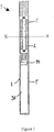
- an aerosol delivery device 1 according to the present invention is disclosed.
- the aerosol delivery device comprises an aerosol delivery device component 1', and an energy store component 1".
- the aerosol delivery device component 1' is removably attachable to the energy store component 1", however it is envisaged that in an alternative embodiment, the aerosol delivery device component 1' and the energy store component 1" are inseparable such that they form as a single component.
- the aerosol delivery device component 1' may be disposable and the energy store component 1" may be reusable. However, it is envisaged that when the two components are formed as a single component then the aerosol delivery device may be disposable or reusable.
- the energy source component 1" comprises a housing holding a battery 30 and an electric circuitry 34 as shown in figure 1 . It should be appreciated that an alternative power source to a battery may be used.
- the aerosol delivery device component 1' is shown in greater detail in Figure 2 and it comprises a housing 2 formed with a mouthpiece 3 at one end and an attachment end formed with a connecting passage 35 at the opposite end.
- the connecting passage 35 electrically connects components held in the aerosol delivery device component 1' with the battery 30 disposed in the energy store component 1" via the electric circuitry 31.
- the housing 2 is further formed with an air passage extending through the aerosol delivery device component 1'.
- the air passage comprises an air inlet 5, plenum chamber 4, chamber inlet 31a, aerosol chamber 6, chamber outlet 31b and outlet aperture 7.
- air is drawn in through the air inlet 5, into the plenum chamber 4, then to the chamber inlet 31a which supplies the air into the aerosol chamber 6, the air then exits the aerosol chamber 6 via the chamber outlet 31b and leaves the aerosol delivery device component 1' via the outlet aperture 7 formed in the mouthpiece 3.
- An aerosol-forming member 10a is located in the aerosol chamber 6.
- the aerosol-forming member is shown in figure 3 and comprises a sheet of material that is configured to wick and heat a solution such that the sheet of material can absorb solution and thereafter heat it up such that it evaporates and forms a vapour.
- the sheet of material is sheet-like in nature and comprises two major opposing surfaces 20, 21.
- the sheet of material may comprise an open-pored structure, foam structure or interconnecting network of pores, all of which form a capillary structure.
- the capillary structure enables the aerosol-forming member 10a to wick or absorb a solution.
- the term "capillary structure" used herein is to be understood as a structure through which liquid or a solution can travel as a result of capillary action.
- the aerosol-forming member 10a may be made of a porous, granular, fibrous or flocculent sintered metal(s) so as to form a capillary structure.
- the aerosol-forming member 10a comprises an open-pored metallic foam or a group of layers of wire mesh or calendered wire mesh which also form capillary structures.
- the aerosol-forming member 10a may be formed from stainless steel.
- the aerosol forming member 10a may be formed with a capillary structure that extends throughout the whole aerosol-forming member 10a such that it is exposed on the two major surfaces 20, 21 of the sheet of material.
- one of the major surfaces 20, 21 may be sealed with a metallic foil or cover that is sintered or attached to said major surface.
- a region of one or both of the major surfaces 20, 21 may be sealed.
- the aerosol-forming member 10a is configured such that the capillary structure does not extend throughout the whole aerosol-forming member.
- a thin support layer may be sintered onto one or both of the major surfaces 20, 21. Such a support layer may be formed from a wire mesh made of stainless steel.
- the material from which the aerosol-forming member 10a is formed is heatable in that it comprises sufficient electrical resistivity so that when current is passed through, the aerosol-forming member 10a heats up to a temperature sufficient to cause the solution held in the capillary structure to evaporate or vaporise.
- the aerosol-forming member 10a can be considered to comprise a heating element formed with a capillary structure such that the heating element and the capillary structure are integrated and form a single entity or unit.
- the sheet of material comprises a single layer configured to wick and heat a solution
- the sheet of material can be described as comprising a heating element and a wick that are arranged in the same surface.
- the aerosol-forming member 10a may comprise any combination of the aforementioned structures and materials, e.g. by providing multiple layers of different structures/ materials, the layers being joined together, e.g. by sintering.
- the aerosol-forming member 10a may comprise any combination of the aforementioned structures and materials, e.g. by providing multiple layers of different structures/ materials, the layers being joined together, e.g. by sintering.
- the aerosol-forming member comprises a sheet of material that is sheet-like in nature and formed from a plurality of layers.
- the aerosol-forming member 10a may comprise a first heatable layer acting as a heating element. This first layer is formed from a material that is configured to be heated up.
- the aerosol-forming member 10a may further comprise a second layer formed with an open-pored structure, foam structure or interconnecting network of pores, all of which form a capillary structure.
- the capillary structure enables the aerosol-forming member 10a to wick or absorb a solution.
- This second layer may be made of a porous, granular, fibrous or flocculent sintered metal(s) so as to form the capillary structure.
- the second layer may comprise an open-pored metallic foam or a group of layers of wire mesh or calendered wire mesh forming the capillary structure.
- the second layer may be made of stainless steel. This second layer acts as a wick.
- the first layer (heating element) and the second layer (wick formed with a capillary structure) are laid on top of each other so as to form a sheet of material having two opposing major surfaces, wherein the capillary structure is exposed on one of the major surfaces.
- the sheet of material can be described as comprising a heating element and a wick arranged in parallel surfaces.
- the first layer also comprises a capillary structure as described above with reference to the second layer, such that the first layer can both heat and wick a solution.
- the sheet of material can be described as comprising a heating element and a wick that are arranged in the same surface and in parallel surfaces.
- the sheet of material comprises a third layer that is similar to the second layer in that it comprises a capillary structure.
- the second and the third layer sandwich the first layer such that the capillary structure is exposed on both major surfaces of the sheet of material.
- the sheet of material according to any of the above described embodiments has a thickness or depth that falls within the range of 20-500 ⁇ m. Alternatively, the thickness falls within the range of 50 to 200 ⁇ m.
- the thickness or depth should be understood as meaning the distance between the two major surfaces 20, 21 of the sheet of material.
- Figures 3 and 4 show the aerosol-forming member 10a in an unfolded state or position and figure 6 shows the aerosol-forming member 10a in a folded state or position.
- the sheet of material has a first or central section 11 and a second and a third section 12, 13 on either side of the central section 11.
- the dashed lines in figure 3 represent the boundaries between the sections 11, 12, 13.
- the second 12 and third 13 sections are formed with slots or notches 14 that extend from opposing long edges 12a, 13a of the aerosol-forming member 10a towards and into the first section 11.
- the second section 12 is formed with five slots 14 and the third section 13 is formed with four slots 14.
- the slots 14 are parallel to one another and spaced apart across the second and third sections 12, 13.
- the electrical terminals 15, 16 are configured to be electrically connected, e.g. via an electric circuitry 34, to a power source, such as the battery 30, so that an electric current can be passed across the aerosol-forming member 10a.
- the electrical terminals 15, 16 may extend from the first section as seen in figure 2 enabling them to slot into connection holes (not shown) of the aerosol delivery device, the connection holes being electrically connected to the power source.
- an electrically conductive wire connected to the power source may be clipped or soldered onto each electrical terminals 15, 16 so that a current can be passed across the aerosol-forming member 10a.
- the electrical terminals are in line with adjacent edges of the second and third sections 12, 13 such that the terminals do not protrude. These terminals may be connected to an electrically conductive wire via a clip and/or the wire may be soldered onto the terminals. It should also be understood that the electrical terminals may be of any other shape and it is envisaged that other means suitable for connecting the electrical terminals to the power source may be used.
- the slots 14 compress the electric field 17 such that it is substantially contained within the first section 11 as illustrated in figure 4 .
- the dashed lines in figure 4 represent boundaries between the first, second and third sections 11, 12, 13.
- the first section 11 is primarily or directly heated up whilst the second and third sections 12, 13 remain relatively unheated, however it should be appreciated that the heat emitted from the first section 11 might cause the second and third sections 12, 13 to heat up slightly.
- the present invention is not limited to an aerosol-forming member 10a comprising slots so as to contain the heat within the first section 11.
- the sheet of material comprises a single layer made up of discrete sections that are chemically and/or mechanically connected to one another.
- the first section 11 is chemically and/or mechanically connected to the second and third sections 12, 13.
- the first section 11 is made of a material of high electrical resistivity whereas the second or the third sections 12, 13 are formed from a material with low electrical resistivity such that when a current is passed through the first section, the electrical field is substantially contained within the first section.
- the first section may also be formed with a capillary structure such that it extends throughout the whole aerosol-forming member. The difference in electrical resistivity results in that the first section 11 heats up relatively to the second and third sections 12, 13.
- the first section 11 comprises a conductive material such as stainless steel wire mesh
- the second and third sections 12, 13 comprise a fibre web or fabric made of glass fibres, glass fibre yarns or any other non-conductive and inert fibre materials.
- the fibre web or fabric of the second and third sections 12, 13 may be joined with the wire mesh of the first section 11 by fritting, that is to say by partially melting the glass phase in the contact zone.
- the aerosol forming member comprises a sheet of material comprising a plurality of layers similar to the un-illustrated embodiment described above.
- the sheet of material comprises discrete sections, a first, second and a third section, such that each section has a plurality of layers.
- the first section is chemically and/or mechanically connected to the second and the third section.
- At least one layer of the first section is made of a material of high electrical resistivity whereas the layers of the second or the third sections are formed from a material with low electrical resistivity such that when a current is passed through the first section, the electrical field is substantially contained within the first section.
- the first section heats up relatively to the second and third sections.
- the sheet of material does not comprise discrete portions or slots so that the first section is heated up relative to the second and third sections 12, 13.
- the sheet of material comprises a non-conductive fibre web or fabric made of glass fibres, glass fibre yarns or any other non-conductive and inert fibre materials.
- the fibre web or fabric is providing the capillary structure and extends throughout all sections of the sheet of material.
- Conductive fibres or wires are incorporated in the fibre web or fabric in a first or central section of the sheet of material making said first or central section heatable.
- the conductive fibres or wires may be made of stainless steel or of a heating wire alloy like Chromium Nickel.
- conductive fibres may replace non-conductive fibres and conductive wires (heating wires) may replace non-conductive yarns.
- FIG 6 shows the aerosol-forming member 10a in a folded state or position.
- the second and third sections 12, 13 are folded about the first section 11 such that the second and third sections 12, 13 enclose the first section 11 and form a channel 18.
- the second and third sections 12, 13 are folded about the first section 11 such that they form a tube or tubular channel. Regions 19a, 19b of the second and third sections 12, 13 overlap such that the channel 18 is completely enclosed in a direction about the first section 11.
- the first section 11 is planar or flat and suspended in the channel 18 such that it extends across the channel 18.
- second and third sections 12, 13 do not have to form a tubular channel 18.
- the second and third sections 12, 13 are folded about the first section 11 such that they form a channel having an oval, square, rectangular or any other type of polygonal cross-section.
- first section 11 is not limited to being planar or flat.
- first section 11 comprises corrugations having ridges and grooves such that it follows a meandering or oscillating path, or a sinusoidal curve.
- the ridges and grooves may extend in a direction parallel to the opposing long edges 12a, 13a of the sheet of material.
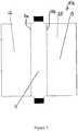
- the third section 13 is omitted such that the aerosol-forming member 10c comprises a first and a second section 11, 12 only.
- the second section 12 extends from the first section 11 and folds about the first section 11 such that the second section 12 forms a channel 18 and the first section 11 is suspended across the channel 18.
- the second section 12 partially encloses the first section 11.
- the second section 12 may extend around a single surface of the first section such that the cross-section of the aerosol-forming member has a semi-circular shape.
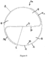
- the aerosol-forming member 10a is located in the aerosol chamber 6 defined by a chamber wall 25 formed from a liquid reservoir matrix.
- the liquid reservoir matrix 26 comprises a capillary structure, for example an interconnecting porous or open-porous structure, such that it can hold a solution or liquid.
- the liquid reservoir matrix 26 may be formed from a fibre material, for example polyethylene or polyester fibres.
- the shape of the aerosol chamber 6 defined by the chamber wall 25 corresponds to the shape of the aerosol-forming member 10a such that when the aerosol-forming member 10a is received in the aerosol chamber 6 it contacts the chamber wall 25.
- the second and third sections 12, 13 contact the chamber wall 25, however it should be understood that only one of the second and third sections 12, 13 may contact the chamber wall 25.
- the aerosol-forming member only comprises a second section 12 as seen in figure 7 then only the second section is in contact with the chamber wall 25. It should also be understood that it is not necessary for the whole second and/or third sections 12, 13 to contact the chamber wall 25. For example, only a portion of the second and/or third sections may contact the chamber wall 25.
- the first section 11 is suspended across the aerosol chamber 6 which can be appreciated form figure 8 .
- the liquid reservoir matrix 26 does not have to be made out of a heat resistant material as it is shielded from the heat of the first section 11 by the second and/or third sections 12, 13 that are not substantially heated up during operation of the aerosol delivery device 1.
- the liquid reservoir matrix 26 holds a solution that is formed into aerosol by the aerosol-forming member 10a.
- the solution is drawn or absorbed into the aerosol-forming member 10a by capillary action via the capillary structure of the second and the third sections 12, 13.
- the solution is spread throughout the whole capillary structure of the aerosol-forming member 10a, i.e. the first, second and third sections 11, 12, 13.
- the first section 11 is heated up, the solution evaporates from the first section 11 so as to form a vapour which upon condensation forms an inhalable aerosol.
- the first section 11 is replenished with solution by capillary action moving solution from the liquid reservoir matrix 26, via the second and third sections 12, 13 to the first section 11. This is described in more detail below.
- the capillarity of the aerosol-forming member 10a may be greater than the capillarity of the liquid reservoir matrix 26 so as to induce flow of solution from the liquid reservoir matrix 26 towards the aerosol-forming member 10a.
- the capillarity is defined by the pore size and the wetting conditions of the respective capillary structures.
- the power source enabling the aerosol-forming member 10a to heat up may be a battery 30.
- the battery 30 is controlled by a controller (not shown) and the electric circuitry 34 which may be mounted on a printed circuit board (PCB).
- the electrical terminals 15, 16 of the aerosol-forming member 10a are electrically connected to the positive and negative terminals of the battery 30 respectively as previously described.
- the electrical resistance of the sheet of material causes the first section 11 of the sheet of material to increase in temperature.
- the resistance of the conductive layer acting as a heating element causes the first section 11 to increase in temperature, which in turn heats up the adjacent non-conductive second and/or third layers of the first section 11.
- the current drawn by the battery 30, and thus the temperature of the sheet of material may be controlled by a switching circuit, e.g. a Power -MOSFET switching circuit, which is provided on the PCB disposed within the housing 2.
- the switching circuit may provide automatic control of the temperature, for example, by using temperature sensors (not shown), or may be controlled by a button or dial (now shown) provided on the housing 2 that may be manipulated by the user.
- the user may manually activate the aerosol delivery device 1 or the aerosol delivery device 1 may be activated automatically as the user starts puffing on the aerosol delivery device 1. This may be achieved by a pressure sensor (not shown) mounted on the PCB and communicating with the plenum chamber 4 via the connecting passage 35.
- the battery 30 provides a potential difference between the electrical terminals 15, 16 of the aerosol-forming member 10a as the aerosol delivery device is activated, causing current to flow between the electrical terminals 15, 16 such that the first section 11 of the sheet of material increases in temperature.
- the heat is contained within the first section 11 due to the slots 14, however it should be appreciated that the heat may be contained within the first section by other means as described above.
- This increase in temperature causes the solution held in the capillary structure of the first section 11 of the sheet of material to evaporate so as to form a vapour.
- the vapour mixes with air drawn into the aerosol delivery device 1 via plenum chamber 4 and chamber inlet 31a by the user.
- the vapour mixes with air in the aerosol chamber 6, and as this occurs the vapour condenses and forms droplets such that an inhalable aerosol is produced.
- the aerosol-forming member 10a according to any of the above described embodiments is located in the housing such that the planes of the major surfaces 20, 21 are parallel to or substantially aligned with the direction of the airflow through the aerosol chamber 6.
- the solution evaporates in a direction transverse to the direction of the airflow.
- the solution is evaporated from both sides in opposite directions as indicated by the arrows in figure 8 .
- the vapour mixes with air so as to form aerosol in the channel 18 formed by the second and/or third sections 12, 13.
- the channel 18 directs the flow of aerosol through the aerosol delivery device towards the user. Furthermore, as a result of the channel 18, solution is evaporated from the major surfaces 20, 21 of the first section 11 in a direction towards the major surfaces 20, 21 of the second and third sections 12, 13. This results in reduced levels of vapour condensing on the chamber wall and other internal components as the major surfaces 20, 21 of the second and third sections 12, 13 are shielding the chamber wall and said other internal components. Furthermore, as the aerosol-forming member 10a cools down aerosol remaining in the aerosol chamber 6 that condenses onto one of the major surfaces 20, 21 will also be reabsorbed into their capillary structure and re-evaporated as the aerosol-forming member 10a is reactivated and heats up again.
- the configuration of the aerosol-forming member 10a forming a channel 18 reduces condensation from forming on the chamber wall, internal components and/or inner walls of the housing 2.
- sponges or other means for absorbing condensation not inhaled by the user that are used in some conventional aerosol delivery devices may be omitted.
- the transfer of condensation heat to the housing 2 may be reduced, making the aerosol delivery device 1 more comfortable for the user to hold.
- the aerosol-forming member 10a After the aerosol-forming member 10a has been activated and aerosol has formed in the channel 18, the aerosol is drawn through the channel 18 as the user continues to inhale. The aerosol then exits the aerosol chamber 6 through a chamber outlet as seen in figure 2 . The aerosol then passes through an optional aerosol refining member 32 provided in the housing 2, causing the aerosol to be cooled.
- the refining member 32 may also contain flavouring agents like menthol that are released into the flow of aerosol before entering the user's mouth via the outlet aperture 7 provided in the mouthpiece 3.
- a pressure drop element or flow resistor 33 is positioned in the plenum chamber 4 so that the flow of air into the aerosol chamber 6 can be controlled.
- the flow resistor 33 may consist of a simple aperture or hole and may be identical with the inlet aperture 5 in the housing 2.
- the flow resistor may consist of a porous body similar to a cigarette filter providing the flow resistance of a conventional cigarette.
- the aerosol-forming member 60a comprises a sheet of material having a first section 61 extending between a second and a third section 62, 63.
- the first section 61 is at a right angle relative to the second and third sections 62, 63, and the second and third sections 62, 63 are facing one another.
- the sheet of material has a U-shaped cross-section which defines a channel 68.
- sheet of material is not limited to having a U-shaped cross-section.
- the second and third sections 62, 63 are not limited to extending at a right angle from the first section 61.
- the second and third sections 62, 63 may extend at an oblique angle relative to the first section 61.
- the second and third sections 62, 63 may extend towards one another or diverge away from one another.
- the aerosol-forming member 60a is similar to the embodiments of the aerosol-forming member 10a described above with reference to figures 1 and 8 and so a detailed description will be omitted.
- the sheet of material has two opposing major surfaces 66, 67 and that the sheet of material may be formed with slots (not shown) such that when an electric current is passed through the sheet of material the first section 61 is heated up relative to the second and third sections 62, 63.
- the first section 61 may be configured to heat up relative to the second and third sections 62, 63 according to any of the embodiments described above with reference to figures 1 to 8 .
- the aerosol-forming member 60a has an open-pored structure, foam structure or interconnecting network of pores, all of which form a capillary structure.
- the capillary structure enables the aerosol-forming member 60a to wick or absorb a solution.
- the sheet of material may comprise a single or a plurality of layers according to the various embodiments described with reference to figures 1 to 8 .
- the third section 63 is omitted such that the sheet of material comprises a first 61 and a second section 62 only extending at an angle relative to one another, for example, the aerosol-forming member may have an L-shaped cross section.
- the first section is configured to be heated up relative to the second section by the use of slots or different materials as described above, or any other means configured to contain the heat to the first section.
- FIG 10 shows a cross-section of an aerosol delivery device 51 similar to the one shown in figure 1 , however the aerosol delivery device 51 comprises two aerosol-forming members 60a as described with reference to figure 9 .
- the aerosol delivery device 51 is similar to that described with reference to figures 1 and 2 , and so a detailed description will be omitted. However, it should be appreciated that the aerosol delivery device comprises a housing 52 with a mouthpiece (not shown), and a passage extending therethrough.
- the passage comprises an inlet aperture, plenum chamber, chamber inlet, aerosol chamber 56, chamber outlet and an outlet aperture.
- the aerosol chamber 56 is defined by a chamber wall comprising two opposing chamber side walls 73, 74 and two opposing chamber main walls 75, 76.
- Each chamber main wall 75, 76 comprises a liquid reservoir matrix 77, 78.
- the liquid reservoir matrices 77, 78 comprise a capillary structure, for example an interconnecting porous or open-porous structure, such that it can hold a solution or liquid.
- the liquid reservoir matrices 77, 78 may be formed from a fibre material, for example polyethylene fibres.
- the capillarity of the aerosol-forming member 60a may be greater than the capillarity of the reservoir matrices 77, 78 so as to induce a flow of solution from the liquid reservoir matrices 77,78 towards the aerosol-forming member 60a.
- the capillarity is defined by the pore size and the wetting conditions of the respective capillary structures.
- a heat shield 79 is located along each of the liquid reservoir matrices 77, 78 such that the heat shields 79 face the aerosol chamber 56.
- the heat shields 79 protect the liquid reservoir matrices 77, 78 from overheating as the temperature of the aerosol-forming member 60a is increased. Furthermore, the heat shields 79 protect individual reservoir matrix fibres from extending towards the heated section 61.
- the heat shields 79 are porous so as to enable a capillary effect across the liquid reservoir matrices 77, 78 to the aerosol-forming member 60a.
- the heat shields 79 may be formed from a thin non-conductive material like oxidised stainless steel wire mesh or inert fabrics like glass or carbon fabrics. It should be understood that the heat shields 79 are optional.
- the present invention is not limited to comprising two liquid reservoir matrices 77, 78. It may comprise more than two liquid reservoir matrices. For example, it may comprise several discrete portions of liquid reservoir matrices. The discrete portions may feature different capillarities so as to optimise the flow of solution to the aerosol-forming member 60a. In alternative embodiment, only one chamber main wall 75, 76 comprises a liquid reservoir matrix and the other chamber main wall may be made of a non-porous material.
- Each sheet of material is located in the aerosol chamber 56 such that their second and third sections 62, 63 are parallel or aligned to one another, as well as in contact with the liquid reservoir matrices 77, 78 of the chamber main walls 75, 76.
- the second or the third sections 62, 63 or a portion of the second and/or third section 62, 63 of each sheet of material may be in contact with the chamber main walls 75, 76.
- the aerosol chamber 56 is provided with heat shields 79, the second and third sections 62, 63 are parallel or aligned, as well as in contact with said heat shields 79.
- only the second or the third sections 62, 63 or a portion of the second and/or third section 62, 63 of each sheet of material may be in contact with the heat shields 79.
- each first section 61 is suspended across the aerosol chamber 56, or more specifically, suspended between the chamber main walls 75, 76.
- the first sections 61 of each sheet of material are parallel to one another, however this is optional.
- the positioning of the sheets of material causes the first sections 61 together with the chamber main walls 75, 76 to define a central channel 80.
- the aerosol-delivery device 51 further comprises a battery (not shown) and an electric circuitry preferably mounted on a printed circuit board (PCB) (not shown) as described with reference to figures 1 and 8 , and the aerosol-delivery device 51 is configured similar to the aerosol delivery device 1 described with reference to figures 1 and 8 such that the ends 82, 83 of the aerosol-forming member 60a as seen in figure 10 , are electrically connected to the positive and negative terminals of the battery respectively.
- the resistance causes the first section 61 of each sheet of material to increase in temperature relative to their second and the third sections 62, 63.
- the aerosol delivery device 51 may comprise a single aerosol-forming member 60a, or two or more aerosol-forming members 60a.
- the user may manually activate the aerosol delivery device 51 or the aerosol delivery device 51 may be activated automatically as the user starts puffing on the aerosol delivery device 1. This may be achieved by a pressure sensor (not shown) mounted on the PCT and communicating with the plenum chamber 4 extending between the inlet aperture and aerosol chamber 56.
- the battery provides a potential difference between the ends 82, 83 or electrical terminals of each sheet of material of the aerosol-forming member 60a as the aerosol delivery device 51 is activated, causing current to flow between the ends 82, 83 of each sheet of material.
- the vapour mixes with air drawn into the aerosol delivery device 51 by the user.
- the vapour mixes with air in the aerosol chamber 56, and as this occurs the vapour condenses and forms droplets such that an inhalable aerosol is produced.
- the aerosol-forming members are located in the housing such that the planes of the major surfaces 66, 67 are parallel to the direction of the airflow.
- the solution evaporates in a direction transverse to the direction of the airflow.
- the solution is evaporated from both sides in opposite directions as indicated by the arrows in figure 10 .
- Vapour is generated in the channels 68 of each sheet of material as well as the central channel 80. The vapour mixes with air flowing through the channels 68, 80 such that aerosol is formed.
- the channels 68, 80 direct the flow of aerosol through the aerosol delivery device 51 towards the user. Furthermore, as a result of the channels 68, solution is evaporated from the major surfaces 67 of the first sections 61 in a direction towards the major surfaces 67 of the second and third sections 62, 63. This results in reduced levels of vapour condensing on the chamber wall and other internal components as the major surfaces 67 of the second and third sections 62, 63 are at least partially shielding the chamber wall and said other internal components. Any condensate built up on the major surfaces 67 of the second and third sections 62,63 will be reabsorbed into the capillary structure of the aerosol-forming member 60a and evaporated as the aerosol-forming member 60a heats up again.
- aerosol remaining in the aerosol chamber 56 may condense onto the major surfaces 66, 67 of each sheet of material such that it is also reabsorbed into the capillary structure of the aerosol-forming members 60a and re-evaporated as the aerosol-forming members 60a are reactivated and heat up again. Condensate resulting from vapour/ aerosol formed in the channel 80 and settling down on the inner surfaces of the chamber main walls 75, 76 will be reabsorbed into the capillary structure of the reservoir matrices 77, 78 and that way resupplied to the aerosol-forming member 60a.
- the channels 68, 80 of the aerosol-forming member shown in figures 8 and 9 also reduce condensation from forming on the chamber walls, internal components and/or inner walls of the housing 52 as they direct the aerosol through part of the aerosol delivery device 51.
- sponges or other means for absorbing condensed aerosol not inhaled by the user that are used in some conventional aerosol delivery devices may be omitted.
- the transfer of condensation heat to the housing 52 may be reduced, making the aerosol delivery device 51 more comfortable for the user to hold.
- the aerosol-forming member 60a After the aerosol-forming member 60a has been activated and aerosol has formed in the channels 68, 80, the aerosol is drawn through the channels 68, 80 as the user continues to inhale. The aerosol then exits the aerosol chamber 56 through a chamber outlet. The aerosol then passes through an optional aerosol refining member (not shown) provided in the housing 52, causing the aerosol to be cooled.
- the refining member may also contain flavouring agents like menthol that are released into the flow of aerosol before entering the user's mouth via the outlet aperture provided in the mouthpiece.
- the solution that has evaporated from the capillary structure of the sheets of material is replaced by solution from the liquid reservoir matrices 77, 78 due to the capillary effect of the capillary structure and the second and third sections being in contact with the liquid reservoir matrices 77, 78.
- Fresh air enters the channels 68, 80 via the inlet aperture, plenum chamber and chamber inlet.
- a pressure drop element or a flow resistor (not shown) is positioned in the plenum chamber so that the flow of air into the aerosol chamber 56 can be controlled.
- the flow resistor may consist of a simple aperture or hole and may be identical with the inlet aperture in the housing 52.
- the flow resistor may consist of a porous body similar to a cigarette filter providing the flow resistance of a conventional cigarette
- the aerosol forming member 10a, 10b, 10c, 60a comprises a sheet of material that has a first section and a second section wherein the first section extends at an angle relative to the second section so as to form a channel. Furthermore, the first section is configured to be heated relative to the second section, and in the embodiments where the aerosol-forming member also comprises a third section, the first section is also configured to be heated relative to the third section.
- the first section being heated relative to the second and third sections is to be understood as the first section being heated to a sufficient temperature so as to evaporate the solution used, whereas although the second and third sections may be heated, they are not heated up to a temperature that is sufficient to evaporate the solution used.
- the first section is configured to be heated up to 100° C and above
- the second and third sections are configured so as to not be heated up to 100° C and above.
- the second and third sections may be configured such that they are not heated above a particular temperature that might affect the function of the chamber wall.
- aerosol-forming member and/or liquid matrix reservoir according to the present invention is not limited to being used with the aerosol delivery device described and shown herein.
- the aerosol-forming member and/or liquid matrix reservoir according to the present invention can be used in any appropriate aerosol delivery device.
- this solution may comprise certain constituents or substances that may have a stimulatory effect on the user. These constituents or substances may be of any kind that is suitable for being delivered via inhalation.
- the solution in which the constituents or substances are held or dissolved may primarily consist of water, ethanol, glycerol, propylene glycol or mixtures of the aforementioned solvents.
- channel used herein is not limited to a specific cross-section. Furthermore, the channel may be completely enclosed about the longitudinal axis of the channel, however it should also be appreciated that the channel may not be enclosed but open along a section parallel to the longitudinal axis of the channel.
- aerosol-forming member 10a, 60a may be oxidised or coated with a non-conductive material so as to prevent a short circuit.
Landscapes
- Health & Medical Sciences (AREA)
- Engineering & Computer Science (AREA)
- Anesthesiology (AREA)
- Biomedical Technology (AREA)
- Heart & Thoracic Surgery (AREA)
- Hematology (AREA)
- Life Sciences & Earth Sciences (AREA)
- Animal Behavior & Ethology (AREA)
- General Health & Medical Sciences (AREA)
- Public Health (AREA)
- Veterinary Medicine (AREA)
- Bioinformatics & Cheminformatics (AREA)
- Pulmonology (AREA)
- Catching Or Destruction (AREA)
- Containers And Packaging Bodies Having A Special Means To Remove Contents (AREA)
- Disinfection, Sterilisation Or Deodorisation Of Air (AREA)
- Thermotherapy And Cooling Therapy Devices (AREA)
- Physical Or Chemical Processes And Apparatus (AREA)
Description
- The invention relates to an aerosol-forming member for an aerosol delivery device. The invention also relates to an aerosol delivery device component comprising the aerosol-forming member according to the invention, and an aerosol delivery device comprising said aerosol delivery device component.
- An aerosol delivery device is a device used for delivering substances into the body via the lungs. One type of aerosol delivery device forms a vapour of a solution in which the substances are dissolved. This vapour condenses within the aerosol delivery device as it mixes with air so as to form droplets or aerosol which is suitable for inhalation. These aerosol delivery devices may comprise a heating element that is configured to evaporate the solution held within the aerosol delivery device so as to form said aerosol. Alternatively, some aerosol delivery devices may utilise piezo atomizers to generate the aerosol.
- Documents
WO 2013/057185 A1 andUS 2013/081623 A1 are disclosing similar aerosol-forming members of aerosol delivery devices. - The invention is defined in
independent claim 1. According to the invention, there is provided an aerosol-forming member comprising a sheet of material configured to wick and to heat a solution, the sheet of material has a first section and a second section, the first section extends at an angle relative to the second section, wherein the first section is configured to be heated relative to the second section. - The second section extends about the first section so as to form a channel in which the first section is suspended. In one embodiment, the sheet of material may further comprise a third section extending from the first section.
- The first section may be configured to be heated relative to the third section.
- In another embodiment, the second and third sections may extend about the first section so as to form a channel in which the first section is suspended.
- In yet another embodiment, the first section may extend between the second and third sections, and the second and third sections extend at an angle relative to the first section so as to form a channel.
- The sheet of material may have a U-shaped cross-section.
- In one embodiment, the channel may be tubular.
- In another embodiment, the first section may be planar.
- In one embodiment, the sheet of material may comprise a capillary structure configured to wick a solution. The capillary structure may be exposed on both sides of the sheet of material.
- In another embodiment, the sheet of material comprises a first layer capable of being heated and a second layer comprising a capillary structure.
- The sheet of material may be formed with slots extending across the second and/or third sections towards the first section so as to enable the first section to be heated relative to the second and/or third sections.
- In one embodiment, the sections are discrete portions joined together, the first section is made of a material that is capable of being heated relative to the material of the other section(s).
- In an alternative embodiment, the sheet of material is formed from a first set of fibres, and a second set of fibres are incorporated into the first section, wherein the second set of fibres is capable of being heated relative to the first set of fibres.
- According to another aspect of the invention, there is provided an aerosol delivery device component comprising an air inlet and an air outlet fluidly communicating via an aerosol chamber defined by a chamber wall, and an aerosol-forming member as described above, wherein the aerosol-forming member is at least partially located in the aerosol chamber. Alternatively, the whole aerosol-forming member may be located in the aerosol chamber.
- In one embodiment, the sheet of material may comprise two opposing major surfaces that are aligned with a direction of flow of air through the aerosol chamber.
- In another embodiment, at least a portion of the second section contacts the chamber wall and the first section is suspended across the aerosol chamber.
- The shape of the aerosol chamber may correspond to the shape of the aerosol-forming member such that the aerosol-forming member contacts the chamber wall.
- In one embodiment, the chamber wall may comprise a liquid reservoir matrix configured to replenish the aerosol-forming member with a solution.
- The liquid reservoir matrix may have a capillary structure.
- In one embodiment, at least the second section contacts the liquid reservoir matrix, and the capillary structure of the aerosol-forming member and the capillary structure of the liquid reservoir matrix fluidly communicate with each other.
- In another embodiment, the aerosol delivery device component further comprises a heat shield locating in the aerosol chamber against the chamber wall.
- According to yet another aspect of the invention, there is provided an aerosol delivery device comprising an aerosol delivery device component as described above.
- Embodiments of the invention will now be described, by way of example only, with reference to the accompanying drawings in which:
-
Figure 1 shows a cross-sectional side view of an aerosol delivery device comprising an aerosol-forming member according to an embodiment of the invention; -
Figure 2 shows a cross-sectional side view of an aerosol delivery device component according to the present embodiment; -
Figure 3 shows a top planar view of an embodiment of an aerosol-forming member in an unfolded state; -
Figure 4 shows a top planar view of an electrical field of the aerosol-forming member infigure 3 ; -
Figure 5 shows a top planar view of another embodiment of an aerosol-forming member in an unfolded state; -
Figure 6 shows a cross-sectional view of an embodiment of an aerosol-forming member in a folded state; -
Figure 7 shows a cross-sectional view of an aerosol-forming member in a folded state according to another embodiment; -
Figure 8 shows a cross-sectional view of the aerosol delivery device along the line X-X ofFigure 1 ; -
Figure 9 shows a cross-sectional view of an aerosol-forming member according to yet another embodiment; and -
Figure 10 shows a cross-sectional view of a further embodiment of an aerosol delivery device comprising the aerosol-forming member shown infigure 9 . - Referring now to
figure 1 , anaerosol delivery device 1 according to the present invention is disclosed. The aerosol delivery device comprises an aerosol delivery device component 1', and anenergy store component 1". The aerosol delivery device component 1' is removably attachable to theenergy store component 1", however it is envisaged that in an alternative embodiment, the aerosol delivery device component 1' and theenergy store component 1" are inseparable such that they form as a single component. - The aerosol delivery device component 1' may be disposable and the
energy store component 1" may be reusable. However, it is envisaged that when the two components are formed as a single component then the aerosol delivery device may be disposable or reusable. - The
energy source component 1" comprises a housing holding abattery 30 and anelectric circuitry 34 as shown infigure 1 . It should be appreciated that an alternative power source to a battery may be used. - The aerosol delivery device component 1' is shown in greater detail in
Figure 2 and it comprises ahousing 2 formed with amouthpiece 3 at one end and an attachment end formed with a connectingpassage 35 at the opposite end. The connectingpassage 35 electrically connects components held in the aerosol delivery device component 1' with thebattery 30 disposed in theenergy store component 1" via the electric circuitry 31. - The
housing 2 is further formed with an air passage extending through the aerosol delivery device component 1'. The air passage comprises anair inlet 5, plenum chamber 4,chamber inlet 31a, aerosol chamber 6,chamber outlet 31b andoutlet aperture 7. In use air is drawn in through theair inlet 5, into the plenum chamber 4, then to thechamber inlet 31a which supplies the air into the aerosol chamber 6, the air then exits the aerosol chamber 6 via thechamber outlet 31b and leaves the aerosol delivery device component 1' via theoutlet aperture 7 formed in themouthpiece 3. - An aerosol-forming
member 10a is located in the aerosol chamber 6. The aerosol-forming member is shown infigure 3 and comprises a sheet of material that is configured to wick and heat a solution such that the sheet of material can absorb solution and thereafter heat it up such that it evaporates and forms a vapour. The sheet of material is sheet-like in nature and comprises two major opposingsurfaces member 10a to wick or absorb a solution. The term "capillary structure" used herein is to be understood as a structure through which liquid or a solution can travel as a result of capillary action. - The aerosol-forming
member 10a may be made of a porous, granular, fibrous or flocculent sintered metal(s) so as to form a capillary structure. In another embodiment, the aerosol-formingmember 10a comprises an open-pored metallic foam or a group of layers of wire mesh or calendered wire mesh which also form capillary structures. The aerosol-formingmember 10a may be formed from stainless steel. Furthermore, theaerosol forming member 10a may be formed with a capillary structure that extends throughout the whole aerosol-formingmember 10a such that it is exposed on the twomajor surfaces major surfaces major surfaces member 10a is configured such that the capillary structure does not extend throughout the whole aerosol-forming member. In yet another un-illustrated embodiment, a thin support layer may be sintered onto one or both of themajor surfaces - The material from which the aerosol-forming
member 10a is formed is heatable in that it comprises sufficient electrical resistivity so that when current is passed through, the aerosol-formingmember 10a heats up to a temperature sufficient to cause the solution held in the capillary structure to evaporate or vaporise. In these embodiments, the aerosol-formingmember 10a can be considered to comprise a heating element formed with a capillary structure such that the heating element and the capillary structure are integrated and form a single entity or unit. - In the above described embodiments wherein the sheet of material comprises a single layer configured to wick and heat a solution, the sheet of material can be described as comprising a heating element and a wick that are arranged in the same surface.
- Alternatively the aerosol-forming
member 10a may comprise any combination of the aforementioned structures and materials, e.g. by providing multiple layers of different structures/ materials, the layers being joined together, e.g. by sintering. One such alternative un-illustrated embodiment will now be described in more detail. - The aerosol-forming member comprises a sheet of material that is sheet-like in nature and formed from a plurality of layers. For example, the aerosol-forming
member 10a may comprise a first heatable layer acting as a heating element. This first layer is formed from a material that is configured to be heated up. The aerosol-formingmember 10a may further comprise a second layer formed with an open-pored structure, foam structure or interconnecting network of pores, all of which form a capillary structure. The capillary structure enables the aerosol-formingmember 10a to wick or absorb a solution. This second layer may be made of a porous, granular, fibrous or flocculent sintered metal(s) so as to form the capillary structure. Alternatively, the second layer may comprise an open-pored metallic foam or a group of layers of wire mesh or calendered wire mesh forming the capillary structure. The second layer may be made of stainless steel. This second layer acts as a wick. - The first layer (heating element) and the second layer (wick formed with a capillary structure) are laid on top of each other so as to form a sheet of material having two opposing major surfaces, wherein the capillary structure is exposed on one of the major surfaces. In this embodiment, the sheet of material can be described as comprising a heating element and a wick arranged in parallel surfaces.
- In an alternative un-illustrated embodiment, the first layer also comprises a capillary structure as described above with reference to the second layer, such that the first layer can both heat and wick a solution. In this embodiment, the sheet of material can be described as comprising a heating element and a wick that are arranged in the same surface and in parallel surfaces.
- In an alternative un-illustrated embodiment, the sheet of material comprises a third layer that is similar to the second layer in that it comprises a capillary structure. The second and the third layer sandwich the first layer such that the capillary structure is exposed on both major surfaces of the sheet of material.
- The sheet of material according to any of the above described embodiments has a thickness or depth that falls within the range of 20-500µm. Alternatively, the thickness falls within the range of 50 to 200µm. The thickness or depth should be understood as meaning the distance between the two
major surfaces -
Figures 3 and4 show the aerosol-formingmember 10a in an unfolded state or position andfigure 6 shows the aerosol-formingmember 10a in a folded state or position. The sheet of material has a first orcentral section 11 and a second and athird section central section 11. The dashed lines infigure 3 represent the boundaries between thesections notches 14 that extend from opposinglong edges 12a, 13a of the aerosol-formingmember 10a towards and into thefirst section 11. In the embodiment shown infigure 3 , thesecond section 12 is formed with fiveslots 14 and thethird section 13 is formed with fourslots 14. Theslots 14 are parallel to one another and spaced apart across the second andthird sections - Opposing free ends of the
first section 11 act aselectrical terminals electrical terminals electric circuitry 34, to a power source, such as thebattery 30, so that an electric current can be passed across the aerosol-formingmember 10a. Theelectrical terminals figure 2 enabling them to slot into connection holes (not shown) of the aerosol delivery device, the connection holes being electrically connected to the power source. Alternatively, an electrically conductive wire connected to the power source may be clipped or soldered onto eachelectrical terminals member 10a. In an alternative un-illustrated embodiment the electrical terminals are in line with adjacent edges of the second andthird sections - When a current is passed through the aerosol-forming
member 10a, theslots 14 compress theelectric field 17 such that it is substantially contained within thefirst section 11 as illustrated infigure 4 . The dashed lines infigure 4 represent boundaries between the first, second andthird sections first section 11 is primarily or directly heated up whilst the second andthird sections first section 11 might cause the second andthird sections - It is envisaged that the present invention is not limited to an aerosol-forming
member 10a comprising slots so as to contain the heat within thefirst section 11. In an alternative embodiment as shown infigure 5 , the sheet of material comprises a single layer made up of discrete sections that are chemically and/or mechanically connected to one another. In other words, thefirst section 11 is chemically and/or mechanically connected to the second andthird sections first section 11 is made of a material of high electrical resistivity whereas the second or thethird sections first section 11 heats up relatively to the second andthird sections - In a specific embodiment the
first section 11 comprises a conductive material such as stainless steel wire mesh, the second andthird sections third sections first section 11 by fritting, that is to say by partially melting the glass phase in the contact zone. - In an alternative un-illustrated embodiment, the aerosol forming member comprises a sheet of material comprising a plurality of layers similar to the un-illustrated embodiment described above. However, in this embodiment, the sheet of material comprises discrete sections, a first, second and a third section, such that each section has a plurality of layers. The first section is chemically and/or mechanically connected to the second and the third section. At least one layer of the first section is made of a material of high electrical resistivity whereas the layers of the second or the third sections are formed from a material with low electrical resistivity such that when a current is passed through the first section, the electrical field is substantially contained within the first section. As a result, the first section heats up relatively to the second and third sections.
- In yet another alternative un-illustrated embodiment, the sheet of material does not comprise discrete portions or slots so that the first section is heated up relative to the second and
third sections - It should be understood that alternative configurations of the aerosol-forming member wherein the heat is contained within the first section relative to the second and third sections are intended to fall within the scope of the present invention.
- Referring now to
figure 6 which shows the aerosol-formingmember 10a in a folded state or position. The second andthird sections first section 11 such that the second andthird sections first section 11 and form achannel 18. The second andthird sections first section 11 such that they form a tube or tubular channel.Regions 19a, 19b of the second andthird sections channel 18 is completely enclosed in a direction about thefirst section 11. Thefirst section 11 is planar or flat and suspended in thechannel 18 such that it extends across thechannel 18. - It should be understood that the second and
third sections tubular channel 18. In alternative un-illustrated embodiments the second andthird sections first section 11 such that they form a channel having an oval, square, rectangular or any other type of polygonal cross-section. - It should also be appreciated that the
first section 11 is not limited to being planar or flat. In an alternative un-illustrated embodiment, thefirst section 11 comprises corrugations having ridges and grooves such that it follows a meandering or oscillating path, or a sinusoidal curve. The ridges and grooves may extend in a direction parallel to the opposinglong edges 12a, 13a of the sheet of material. - In yet another embodiment as shown in
figure 7 , thethird section 13 is omitted such that the aerosol-forming member 10c comprises a first and asecond section second section 12 extends from thefirst section 11 and folds about thefirst section 11 such that thesecond section 12 forms achannel 18 and thefirst section 11 is suspended across thechannel 18. Alternatively, thesecond section 12 partially encloses thefirst section 11. For example, thesecond section 12 may extend around a single surface of the first section such that the cross-section of the aerosol-forming member has a semi-circular shape. - Referring now to
figure 8 , the aerosol-formingmember 10a is located in the aerosol chamber 6 defined by achamber wall 25 formed from a liquid reservoir matrix. Theliquid reservoir matrix 26 comprises a capillary structure, for example an interconnecting porous or open-porous structure, such that it can hold a solution or liquid. Theliquid reservoir matrix 26 may be formed from a fibre material, for example polyethylene or polyester fibres. - The shape of the aerosol chamber 6 defined by the
chamber wall 25 corresponds to the shape of the aerosol-formingmember 10a such that when the aerosol-formingmember 10a is received in the aerosol chamber 6 it contacts thechamber wall 25. In the embodiment shown infigure 8 , the second andthird sections chamber wall 25, however it should be understood that only one of the second andthird sections chamber wall 25. Alternatively, if the aerosol-forming member only comprises asecond section 12 as seen infigure 7 then only the second section is in contact with thechamber wall 25. It should also be understood that it is not necessary for the whole second and/orthird sections chamber wall 25. For example, only a portion of the second and/or third sections may contact thechamber wall 25. - In the embodiments of the present invention, the
first section 11 is suspended across the aerosol chamber 6 which can be appreciated formfigure 8 . - Advantageously, the
liquid reservoir matrix 26 does not have to be made out of a heat resistant material as it is shielded from the heat of thefirst section 11 by the second and/orthird sections aerosol delivery device 1. - The
liquid reservoir matrix 26 holds a solution that is formed into aerosol by the aerosol-formingmember 10a. The solution is drawn or absorbed into the aerosol-formingmember 10a by capillary action via the capillary structure of the second and thethird sections member 10a, i.e. the first, second andthird sections first section 11 is heated up, the solution evaporates from thefirst section 11 so as to form a vapour which upon condensation forms an inhalable aerosol. Thereafter, and even during the heating, thefirst section 11 is replenished with solution by capillary action moving solution from theliquid reservoir matrix 26, via the second andthird sections first section 11. This is described in more detail below. - The capillarity of the aerosol-forming
member 10a may be greater than the capillarity of theliquid reservoir matrix 26 so as to induce flow of solution from theliquid reservoir matrix 26 towards the aerosol-formingmember 10a. The capillarity is defined by the pore size and the wetting conditions of the respective capillary structures. - As previously described, the power source enabling the aerosol-forming
member 10a to heat up may be abattery 30. Thebattery 30 is controlled by a controller (not shown) and theelectric circuitry 34 which may be mounted on a printed circuit board (PCB). Theelectrical terminals member 10a are electrically connected to the positive and negative terminals of thebattery 30 respectively as previously described. When current is drawn from thebattery 30 and through the sheet of material, the electrical resistance of the sheet of material causes thefirst section 11 of the sheet of material to increase in temperature. In the embodiment wherein the sheet of material comprises several layers, the resistance of the conductive layer acting as a heating element causes thefirst section 11 to increase in temperature, which in turn heats up the adjacent non-conductive second and/or third layers of thefirst section 11. The current drawn by thebattery 30, and thus the temperature of the sheet of material may be controlled by a switching circuit, e.g. a Power -MOSFET switching circuit, which is provided on the PCB disposed within thehousing 2. The switching circuit may provide automatic control of the temperature, for example, by using temperature sensors (not shown), or may be controlled by a button or dial (now shown) provided on thehousing 2 that may be manipulated by the user. - Operation of the
aerosol delivery device 1 will now be described with reference tofigures 1 and8 . In use, the user may manually activate theaerosol delivery device 1 or theaerosol delivery device 1 may be activated automatically as the user starts puffing on theaerosol delivery device 1. This may be achieved by a pressure sensor (not shown) mounted on the PCB and communicating with the plenum chamber 4 via the connectingpassage 35. In either embodiment, thebattery 30 provides a potential difference between theelectrical terminals member 10a as the aerosol delivery device is activated, causing current to flow between theelectrical terminals first section 11 of the sheet of material increases in temperature. The heat is contained within thefirst section 11 due to theslots 14, however it should be appreciated that the heat may be contained within the first section by other means as described above. This increase in temperature causes the solution held in the capillary structure of thefirst section 11 of the sheet of material to evaporate so as to form a vapour. The vapour mixes with air drawn into theaerosol delivery device 1 via plenum chamber 4 andchamber inlet 31a by the user. The vapour mixes with air in the aerosol chamber 6, and as this occurs the vapour condenses and forms droplets such that an inhalable aerosol is produced. - The aerosol-forming
member 10a according to any of the above described embodiments is located in the housing such that the planes of themajor surfaces member 10a and it is heated up such that the solution evaporates, the solution evaporates in a direction transverse to the direction of the airflow. In the embodiments wherein the capillary structure is exposed on both sides of the sheet of material, the solution is evaporated from both sides in opposite directions as indicated by the arrows infigure 8 . The vapour mixes with air so as to form aerosol in thechannel 18 formed by the second and/orthird sections channel 18 directs the flow of aerosol through the aerosol delivery device towards the user. Furthermore, as a result of thechannel 18, solution is evaporated from themajor surfaces first section 11 in a direction towards themajor surfaces third sections major surfaces third sections member 10a cools down aerosol remaining in the aerosol chamber 6 that condenses onto one of themajor surfaces member 10a is reactivated and heats up again. - The configuration of the aerosol-forming
member 10a forming achannel 18 reduces condensation from forming on the chamber wall, internal components and/or inner walls of thehousing 2. Thus, sponges or other means for absorbing condensation not inhaled by the user that are used in some conventional aerosol delivery devices may be omitted. This results in a more compactaerosol delivery device 1, as well as a simplified manufacturing process and reduced costs. Furthermore, by reducing the amount of aerosol and/or vapour from condensing onto inner walls of thehousing 2, the transfer of condensation heat to thehousing 2 may be reduced, making theaerosol delivery device 1 more comfortable for the user to hold. - After the aerosol-forming
member 10a has been activated and aerosol has formed in thechannel 18, the aerosol is drawn through thechannel 18 as the user continues to inhale. The aerosol then exits the aerosol chamber 6 through a chamber outlet as seen infigure 2 . The aerosol then passes through an optionalaerosol refining member 32 provided in thehousing 2, causing the aerosol to be cooled. The refiningmember 32 may also contain flavouring agents like menthol that are released into the flow of aerosol before entering the user's mouth via theoutlet aperture 7 provided in themouthpiece 3. Meanwhile, the solution that has evaporated from the capillary structure of thefirst section 11 of the sheet of material is replaced by fresh solution from theliquid reservoir matrix 26 due to the capillary effect of the capillary structure as described above and the second and/or third section being in contact with theliquid reservoir matrix 26. Fresh air enters thechannel 18 via theinlet aperture 5, plenum chamber 4 andchamber inlet 31a. In one embodiment, a pressure drop element or flow resistor 33 is positioned in the plenum chamber 4 so that the flow of air into the aerosol chamber 6 can be controlled. The flow resistor 33 may consist of a simple aperture or hole and may be identical with theinlet aperture 5 in thehousing 2. Alternatively the flow resistor may consist of a porous body similar to a cigarette filter providing the flow resistance of a conventional cigarette. - Referring now to
figure 9 , another embodiment of an aerosol-formingmember 60a is shown. The aerosol-formingmember 60a comprises a sheet of material having afirst section 61 extending between a second and athird section first section 61 is at a right angle relative to the second andthird sections third sections channel 68. - It should be understood that sheet of material is not limited to having a U-shaped cross-section. Thus, the second and
third sections first section 61. The second andthird sections first section 61. The second andthird sections - The aerosol-forming
member 60a is similar to the embodiments of the aerosol-formingmember 10a described above with reference tofigures 1 and8 and so a detailed description will be omitted. However, it should be understood that the sheet of material has two opposingmajor surfaces first section 61 is heated up relative to the second andthird sections first section 61 may be configured to heat up relative to the second andthird sections figures 1 to 8 . Furthermore, it should be understood that the aerosol-formingmember 60a has an open-pored structure, foam structure or interconnecting network of pores, all of which form a capillary structure. The capillary structure enables the aerosol-formingmember 60a to wick or absorb a solution. The sheet of material may comprise a single or a plurality of layers according to the various embodiments described with reference tofigures 1 to 8 . - It is also envisaged that in an alternative un-illustrated embodiment the
third section 63 is omitted such that the sheet of material comprises a first 61 and asecond section 62 only extending at an angle relative to one another, for example, the aerosol-forming member may have an L-shaped cross section. In this embodiment, the first section is configured to be heated up relative to the second section by the use of slots or different materials as described above, or any other means configured to contain the heat to the first section. - Referring now to
figure 10 which shows a cross-section of anaerosol delivery device 51 similar to the one shown infigure 1 , however theaerosol delivery device 51 comprises two aerosol-formingmembers 60a as described with reference tofigure 9 . - The
aerosol delivery device 51 is similar to that described with reference tofigures 1 and2 , and so a detailed description will be omitted. However, it should be appreciated that the aerosol delivery device comprises ahousing 52 with a mouthpiece (not shown), and a passage extending therethrough. The passage comprises an inlet aperture, plenum chamber, chamber inlet,aerosol chamber 56, chamber outlet and an outlet aperture. - Two of the aerosol-forming
members 60a described with reference tofigure 9 are located in theaerosol chamber 56. Theaerosol chamber 56 is defined by a chamber wall comprising two opposingchamber side walls main walls main wall liquid reservoir matrix 77, 78. Theliquid reservoir matrices 77, 78 comprise a capillary structure, for example an interconnecting porous or open-porous structure, such that it can hold a solution or liquid. Theliquid reservoir matrices 77, 78 may be formed from a fibre material, for example polyethylene fibres. - The capillarity of the aerosol-forming
member 60a may be greater than the capillarity of thereservoir matrices 77, 78 so as to induce a flow of solution from theliquid reservoir matrices 77,78 towards the aerosol-formingmember 60a. The capillarity is defined by the pore size and the wetting conditions of the respective capillary structures. - A
heat shield 79 is located along each of theliquid reservoir matrices 77, 78 such that theheat shields 79 face theaerosol chamber 56. Theheat shields 79 protect theliquid reservoir matrices 77, 78 from overheating as the temperature of the aerosol-formingmember 60a is increased. Furthermore, theheat shields 79 protect individual reservoir matrix fibres from extending towards theheated section 61. Theheat shields 79 are porous so as to enable a capillary effect across theliquid reservoir matrices 77, 78 to the aerosol-formingmember 60a. Theheat shields 79 may be formed from a thin non-conductive material like oxidised stainless steel wire mesh or inert fabrics like glass or carbon fabrics. It should be understood that theheat shields 79 are optional. - It should also be understood that the present invention is not limited to comprising two
liquid reservoir matrices 77, 78. It may comprise more than two liquid reservoir matrices. For example, it may comprise several discrete portions of liquid reservoir matrices. The discrete portions may feature different capillarities so as to optimise the flow of solution to the aerosol-formingmember 60a. In alternative embodiment, only one chambermain wall - Each sheet of material is located in the
aerosol chamber 56 such that their second andthird sections liquid reservoir matrices 77, 78 of the chambermain walls third sections third section main walls aerosol chamber 56 is provided withheat shields 79, the second andthird sections third sections third section - The sheets of material are positioned in the
aerosol chamber 56 such that eachfirst section 61 is suspended across theaerosol chamber 56, or more specifically, suspended between the chambermain walls first sections 61 of each sheet of material are parallel to one another, however this is optional. - The positioning of the sheets of material causes the
first sections 61 together with the chambermain walls central channel 80. - Ends 82, 83 of each sheet of material are sandwiched between the
housing 52 and theheat shields 79 as seen infigure 10 . This enables each sheet of material to be held in place. In the embodiment wherein theaerosol chamber 56 is not provided withheat shields 79, the ends 82, 83 of the sheets of material are sandwiched between thehousing 52 and the chambermain walls - The aerosol-
delivery device 51 further comprises a battery (not shown) and an electric circuitry preferably mounted on a printed circuit board (PCB) (not shown) as described with reference tofigures 1 and8 , and the aerosol-delivery device 51 is configured similar to theaerosol delivery device 1 described with reference tofigures 1 and8 such that the ends 82, 83 of the aerosol-formingmember 60a as seen infigure 10 , are electrically connected to the positive and negative terminals of the battery respectively. When current is drawn from the battery and through the sheet of material of each aerosol-formingmember 60a, the resistance causes thefirst section 61 of each sheet of material to increase in temperature relative to their second and thethird sections - It is envisaged that the
aerosol delivery device 51 may comprise a single aerosol-formingmember 60a, or two or more aerosol-formingmembers 60a. - Operation of the
aerosol delivery device 51 will now be described with reference tofigures 8 and9 . Similar to the aerosol-delivery device 1 described with reference tofigures 1 to 6 , the user may manually activate theaerosol delivery device 51 or theaerosol delivery device 51 may be activated automatically as the user starts puffing on theaerosol delivery device 1. This may be achieved by a pressure sensor (not shown) mounted on the PCT and communicating with the plenum chamber 4 extending between the inlet aperture andaerosol chamber 56. In either embodiment, the battery provides a potential difference between theends member 60a as theaerosol delivery device 51 is activated, causing current to flow between theends first section 61 of each sheet of material to increase in temperature. This increase in temperature causes the solution held in the capillary structure of thefirst section 61 of each sheet of material to evaporate so as to form a vapour. The vapour mixes with air drawn into theaerosol delivery device 51 by the user. The vapour mixes with air in theaerosol chamber 56, and as this occurs the vapour condenses and forms droplets such that an inhalable aerosol is produced. - The aerosol-forming members are located in the housing such that the planes of the
major surfaces member 60a and they are heated up such that the solution evaporates, the solution evaporates in a direction transverse to the direction of the airflow. In the embodiments wherein the capillary structure is exposed on both sides of the sheet of material, the solution is evaporated from both sides in opposite directions as indicated by the arrows infigure 10 . Vapour is generated in thechannels 68 of each sheet of material as well as thecentral channel 80. The vapour mixes with air flowing through thechannels channels aerosol delivery device 51 towards the user. Furthermore, as a result of thechannels 68, solution is evaporated from themajor surfaces 67 of thefirst sections 61 in a direction towards themajor surfaces 67 of the second andthird sections major surfaces 67 of the second andthird sections major surfaces 67 of the second andthird sections member 60a and evaporated as the aerosol-formingmember 60a heats up again. Furthermore, as the aerosol-formingmember 60a cools down aerosol remaining in theaerosol chamber 56 may condense onto themajor surfaces members 60a and re-evaporated as the aerosol-formingmembers 60a are reactivated and heat up again. Condensate resulting from vapour/ aerosol formed in thechannel 80 and settling down on the inner surfaces of the chambermain walls reservoir matrices 77, 78 and that way resupplied to the aerosol-formingmember 60a. Similar to the aerosol-formingmember 10a described with reference tofigures 1 to 6 , thechannels figures 8 and9 also reduce condensation from forming on the chamber walls, internal components and/or inner walls of thehousing 52 as they direct the aerosol through part of theaerosol delivery device 51. Thus, sponges or other means for absorbing condensed aerosol not inhaled by the user that are used in some conventional aerosol delivery devices may be omitted. This results in a more compactaerosol delivery device 51, as well as simplified manufacturing processes and reduced costs. Furthermore, by reducing the amount of aerosol and/or vapour from condensing onto the inner walls of thehousing 52, the transfer of condensation heat to thehousing 52 may be reduced, making theaerosol delivery device 51 more comfortable for the user to hold. - After the aerosol-forming
member 60a has been activated and aerosol has formed in thechannels channels aerosol chamber 56 through a chamber outlet. The aerosol then passes through an optional aerosol refining member (not shown) provided in thehousing 52, causing the aerosol to be cooled. The refining member may also contain flavouring agents like menthol that are released into the flow of aerosol before entering the user's mouth via the outlet aperture provided in the mouthpiece. Meanwhile, the solution that has evaporated from the capillary structure of the sheets of material is replaced by solution from theliquid reservoir matrices 77, 78 due to the capillary effect of the capillary structure and the second and third sections being in contact with theliquid reservoir matrices 77, 78. Fresh air enters thechannels aerosol chamber 56 can be controlled. The flow resistor may consist of a simple aperture or hole and may be identical with the inlet aperture in thehousing 52. Alternatively the flow resistor may consist of a porous body similar to a cigarette filter providing the flow resistance of a conventional cigarette - In any of the embodiments described herein the
aerosol forming member - It should be understood that the aerosol-forming member and/or liquid matrix reservoir according to the present invention is not limited to being used with the aerosol delivery device described and shown herein. The aerosol-forming member and/or liquid matrix reservoir according to the present invention can be used in any appropriate aerosol delivery device.
- The above described embodiments of the aerosol-forming
member 10a, 6oa of theaerosol delivery device - It should be understood that the term "channel" used herein is not limited to a specific cross-section. Furthermore, the channel may be completely enclosed about the longitudinal axis of the channel, however it should also be appreciated that the channel may not be enclosed but open along a section parallel to the longitudinal axis of the channel.
- It is also envisaged that the aerosol-forming
member - In order to address various issues and advance the art, the entirety of this disclosure shows by way of illustration various embodiments in which the claimed invention(s) may be practiced and provide for a superior aerosol-forming member, aerosol delivery device component and aerosol delivery device. The advantages and features of the disclosure are of a representative sample of embodiments only, and are not exhaustive and/or exclusive. They are presented only to assist in understanding and teach the claimed features. It is to be understood that advantages, embodiments, examples, functions, features, structures, and/or other aspects of the disclosure are not to be considered limitations on the disclosure as defined by the claims or limitations on equivalents to the claims, and that other embodiments may be utilised and modifications maybe made without departing from the scope of the disclosure. Various embodiments may suitably comprise, consist of, or consist essentially of, various combinations of the disclosed elements, components, features, parts, steps, means, etc. In addition, the disclosure includes other inventions not presently claimed, but which may be claimed in future.
Claims (15)
- An aerosol-forming member (10a, 10b, 10c, 60a) comprising a sheet of material configured to wick and to heat a solution, the sheet of material has a first section (11, 61) and a second section (12, 62), the first section (11, 61) extends at an angle relative to the second section (12, 62), wherein the first section (11, 61) is configured to be heated relative to the second section (12, 62), and wherein the second section (12, 62) extends about the first section (11, 61) so as to form a channel (18, 68) in which the first section (11, 61) is suspended.
- An aerosol-forming member according to claim 1, wherein the sheet of material further comprises a third section (13, 63) extending from the first section (11, 61).
- An aerosol-forming member according to claim 2, wherein the first section (11, 61) is configured to be heated relative to the third section (13, 63).
- An aerosol-forming member according to claim 2 or 3, wherein the second and third sections (12, 13, 62, 63) extend about the first section (11, 61) so as to form a channel (18, 68) in which the first section (11, 61) is suspended.
- An aerosol-forming member according to claims 2, 3 or 4, wherein the first section (11, 61) extends between the second and third sections (12, 13, 62, 63), and the second and third sections (12, 13, 62, 63) extend at an angle relative to the first section (11, 61) so as to form a channel (18, 68).
- An aerosol-forming member according to any one of the preceding claims, wherein the sheet of material comprises a capillary structure configured to wick a solution.
- An aerosol-forming member according to any of claims 1 to 6, wherein the sheet of material comprises a first layer capable of being heated and a second layer comprising a capillary structure.
- An aerosol-forming member according to any one of the preceding claims, wherein the sheet of material is formed with slots (14) extending across the second and/or third sections (12, 13, 62, 63) towards the first section (11, 61) so as to enable the first section (11, 61) to be heated relative to the second and/or third sections (12, 13, 62, 63).
- An aerosol-forming member according to any of claims 1 to 7, wherein the sections are discrete portions joined together, and the first section (11, 61) is made of a material that is capable of being heated relative to the material of the other section(s).
- An aerosol delivery device component (1') comprising an air inlet (5) and an air outlet (7) fluidly communicating via an aerosol chamber (6, 56) defined by a chamber wall (25, 75, 76), and an aerosol-forming member (10a, 10b, 10c, 60a) according to any of claims 1 to 9, wherein the aerosol-forming member is at least partially located in the aerosol chamber (6, 56).
- An aerosol delivery device component according to claim 10, wherein the sheet of material comprises two opposing major surfaces (20, 21) that are aligned with a direction of flow of air through the aerosol chamber.
- An aerosol delivery device component according to claim 10 or 11, wherein at least a portion of the second section (12, 62) contacts the chamber wall (25, 75, 76) and the first section (11, 61) is suspended across the aerosol chamber (6, 56).
- An aerosol delivery device component according to claim 10 to 12, wherein the chamber wall (25, 75, 76) comprises a liquid reservoir matrix (26, 77, 78) configured to replenish the aerosol-forming member with a solution.
- An aerosol delivery device component according to claim 13, wherein the liquid reservoir matrix (26, 77, 78) has a capillary structure.
- An aerosol delivery device (1, 51) comprising an aerosol delivery device component as claimed in claims 10 to 14 or an aerosol-forming member as claimed in claims 1 to 9.
Priority Applications (1)
| Application Number | Priority Date | Filing Date | Title |
|---|---|---|---|
| PL15702555T PL3099189T3 (en) | 2014-01-29 | 2015-01-28 | Aerosol-forming member |
Applications Claiming Priority (2)
| Application Number | Priority Date | Filing Date | Title |
|---|---|---|---|
| GBGB1401519.2A GB201401519D0 (en) | 2014-01-29 | 2014-01-29 | Aerosol-forming member |
| PCT/GB2015/050193 WO2015114327A1 (en) | 2014-01-29 | 2015-01-28 | Aerosol-forming member |
Publications (2)
| Publication Number | Publication Date |
|---|---|
| EP3099189A1 EP3099189A1 (en) | 2016-12-07 |
| EP3099189B1 true EP3099189B1 (en) | 2018-11-14 |
Family
ID=50287751
Family Applications (1)
| Application Number | Title | Priority Date | Filing Date |
|---|---|---|---|
| EP15702555.2A Active EP3099189B1 (en) | 2014-01-29 | 2015-01-28 | Aerosol-forming member |
Country Status (7)
| Country | Link |
|---|---|
| US (1) | US10314337B2 (en) |
| EP (1) | EP3099189B1 (en) |
| CN (1) | CN105934171B (en) |
| GB (1) | GB201401519D0 (en) |
| PL (1) | PL3099189T3 (en) |
| RU (1) | RU2661723C2 (en) |
| WO (1) | WO2015114327A1 (en) |
Families Citing this family (22)
| Publication number | Priority date | Publication date | Assignee | Title |
|---|---|---|---|---|
| ES2543312T3 (en) | 2011-02-11 | 2015-08-18 | Batmark Limited | Component for inhaler |
| AT510837B1 (en) | 2011-07-27 | 2012-07-15 | Helmut Dr Buchberger | INHALATORKOMPONENTE |
| GB201401524D0 (en) | 2014-01-29 | 2014-03-12 | Batmark Ltd | Aerosol-forming member |
| GB201401520D0 (en) * | 2014-01-29 | 2014-03-12 | Batmark Ltd | Aerosol-forming member |
| GB201401519D0 (en) * | 2014-01-29 | 2014-03-12 | Batmark Ltd | Aerosol-forming member |
| GB201411483D0 (en) | 2014-06-27 | 2014-08-13 | Batmark Ltd | Vaporizer Assembly |
| GB2533135B (en) * | 2014-12-11 | 2020-11-11 | Nicoventures Holdings Ltd | Aerosol provision systems |
| CN107809921B (en) | 2015-08-07 | 2021-06-25 | 菲利普莫里斯生产公司 | Aerosol-generating system with enhanced airflow management |
| EP3331387B1 (en) | 2015-08-07 | 2020-02-19 | Philip Morris Products S.a.s. | An aerosol-generating system with enhanced airflow management |
| CN205337599U (en) | 2015-10-22 | 2016-06-29 | 深圳麦克韦尔股份有限公司 | Electron cigarette and atomization component and atomizing component thereof |
| CA3103090C (en) | 2016-04-27 | 2023-03-28 | Nicoventures Trading Limited | Electronic aerosol provision system and vaporizer therefor |
| CA3029388C (en) * | 2016-06-27 | 2022-09-06 | Japan Tobacco Inc. | Cartridge for aerosol inhaler, aerosol inhaler provided with same, and heat-generating sheet for aerosol inhaler |
| US10617151B2 (en) | 2016-07-21 | 2020-04-14 | Rai Strategic Holdings, Inc. | Aerosol delivery device with a liquid transport element comprising a porous monolith and related method |
| RU2747956C2 (en) | 2016-11-30 | 2021-05-17 | Филип Моррис Продактс С.А. | Aerosol generating system with outer housing |
| GB201707805D0 (en) * | 2017-05-16 | 2017-06-28 | Nicoventures Holdings Ltd | Atomiser for vapour provision device |
| US20190104764A1 (en) * | 2017-10-11 | 2019-04-11 | Altria Client Services Llc | Folded heater for electronic vaping device |
| USD870375S1 (en) | 2017-10-11 | 2019-12-17 | Altria Client Services Llc | Battery for an electronic vaping device |
| US10772356B2 (en) | 2017-10-11 | 2020-09-15 | Altria Client Services Llc | Electronic vaping device including transfer pad with oriented fibers |
| WO2019105812A1 (en) * | 2017-11-30 | 2019-06-06 | Philip Morris Products S.A. | Systems for generating a liquid aerosol |
| US10687557B2 (en) | 2017-12-29 | 2020-06-23 | Altria Client Services Llc | Electronic vaping device with outlet-end illumination |
| CN110638101B (en) * | 2019-09-30 | 2024-07-05 | 深圳麦克韦尔科技有限公司 | Atomizer and electronic atomization device |
| CN113712279A (en) * | 2021-08-27 | 2021-11-30 | 深圳麦克韦尔科技有限公司 | Electronic atomization device, atomizer, atomization core and preparation method of atomization core |
Family Cites Families (20)
| Publication number | Priority date | Publication date | Assignee | Title |
|---|---|---|---|---|
| NL134797C (en) * | 1939-07-14 | 1900-01-01 | Hartford Empire Co | |
| KR100289448B1 (en) * | 1997-07-23 | 2001-05-02 | 미즈노 마사루 | Flavor generator |
| GB2421436B (en) | 2004-12-21 | 2009-12-30 | Carbonate Ltd | Wick assemblies |
| US7726320B2 (en) | 2006-10-18 | 2010-06-01 | R. J. Reynolds Tobacco Company | Tobacco-containing smoking article |
| CN201238609Y (en) | 2008-07-21 | 2009-05-20 | 北京格林世界科技发展有限公司 | Electronic atomizer for electronic cigarette |
| AT507187B1 (en) * | 2008-10-23 | 2010-03-15 | Helmut Dr Buchberger | INHALER |
| EP2340729A1 (en) * | 2009-12-30 | 2011-07-06 | Philip Morris Products S.A. | An improved heater for an electrically heated aerosol generating system |
| AT509046B1 (en) * | 2010-03-10 | 2011-06-15 | Helmut Dr Buchberger | FLAT EVAPORATOR |
| RU94815U1 (en) * | 2010-03-18 | 2010-06-10 | Евгений Иванович Евсюков | ELECTRONIC CIGARETTE |
| US8746240B2 (en) * | 2010-05-15 | 2014-06-10 | Nate Terry & Michael Edward Breede | Activation trigger for a personal vaporizing inhaler |
| ES2543312T3 (en) * | 2011-02-11 | 2015-08-18 | Batmark Limited | Component for inhaler |
| AT510837B1 (en) * | 2011-07-27 | 2012-07-15 | Helmut Dr Buchberger | INHALATORKOMPONENTE |
| AT511344B1 (en) * | 2011-10-21 | 2012-11-15 | Helmut Dr Buchberger | INHALATORKOMPONENTE |
| GB201401520D0 (en) * | 2014-01-29 | 2014-03-12 | Batmark Ltd | Aerosol-forming member |
| GB201401524D0 (en) | 2014-01-29 | 2014-03-12 | Batmark Ltd | Aerosol-forming member |
| GB201401519D0 (en) * | 2014-01-29 | 2014-03-12 | Batmark Ltd | Aerosol-forming member |
| GB201407426D0 (en) * | 2014-04-28 | 2014-06-11 | Batmark Ltd | Aerosol forming component |
| GB2529201A (en) * | 2014-08-13 | 2016-02-17 | Batmark Ltd | Device and method |
| US11717845B2 (en) * | 2016-03-30 | 2023-08-08 | Altria Client Services Llc | Vaping device and method for aerosol-generation |
| US11571025B2 (en) * | 2016-05-04 | 2023-02-07 | Altria Client Services Llc | Aerosol-generating article having a cover layer |
-
2014
- 2014-01-29 GB GBGB1401519.2A patent/GB201401519D0/en not_active Ceased
-
2015
- 2015-01-28 EP EP15702555.2A patent/EP3099189B1/en active Active
- 2015-01-28 CN CN201580006116.9A patent/CN105934171B/en active Active
- 2015-01-28 PL PL15702555T patent/PL3099189T3/en unknown
- 2015-01-28 WO PCT/GB2015/050193 patent/WO2015114327A1/en active Application Filing
- 2015-01-28 US US15/115,583 patent/US10314337B2/en active Active
- 2015-01-28 RU RU2016131329A patent/RU2661723C2/en active
Non-Patent Citations (1)
| Title |
|---|
| None * |
Also Published As
| Publication number | Publication date |
|---|---|
| US20170188630A1 (en) | 2017-07-06 |
| CN105934171B (en) | 2019-05-31 |
| CN105934171A (en) | 2016-09-07 |
| GB201401519D0 (en) | 2014-03-12 |
| WO2015114327A1 (en) | 2015-08-06 |
| RU2661723C2 (en) | 2018-07-19 |
| EP3099189A1 (en) | 2016-12-07 |
| RU2016131329A (en) | 2018-02-01 |
| US10314337B2 (en) | 2019-06-11 |
| PL3099189T3 (en) | 2019-07-31 |
Similar Documents
| Publication | Publication Date | Title |
|---|---|---|
| EP3099189B1 (en) | Aerosol-forming member | |
| EP3099190B1 (en) | Aerosol-forming member | |
| US11116919B2 (en) | Aerosol delivery device and method utilizing a flavoring reservoir | |
| US11058152B2 (en) | Vaporizer assembly having a vaporizer and a matrix | |
| US10188144B2 (en) | Aerosol-forming member comprising a sheet of material having a non-planar inner major surface |
Legal Events
| Date | Code | Title | Description |
|---|---|---|---|
| PUAI | Public reference made under article 153(3) epc to a published international application that has entered the european phase |
Free format text: ORIGINAL CODE: 0009012 |
|
| STAA | Information on the status of an ep patent application or granted ep patent |
Free format text: STATUS: REQUEST FOR EXAMINATION WAS MADE |
|
| 17P | Request for examination filed |
Effective date: 20160829 |
|
| AK | Designated contracting states |
Kind code of ref document: A1 Designated state(s): AL AT BE BG CH CY CZ DE DK EE ES FI FR GB GR HR HU IE IS IT LI LT LU LV MC MK MT NL NO PL PT RO RS SE SI SK SM TR |
|
| AX | Request for extension of the european patent |
Extension state: BA ME |
|
| DAX | Request for extension of the european patent (deleted) | ||
| REG | Reference to a national code |
Ref country code: HK Ref legal event code: DE Ref document number: 1230443 Country of ref document: HK |
|
| REG | Reference to a national code |
Ref country code: DE Ref legal event code: R079 Ref document number: 602015019794 Country of ref document: DE Free format text: PREVIOUS MAIN CLASS: A24F0047000000 Ipc: H05B0003340000 |
|
| RIC1 | Information provided on ipc code assigned before grant |
Ipc: A61M 15/06 20060101ALI20180416BHEP Ipc: A61M 11/04 20060101ALI20180416BHEP Ipc: H05B 3/34 20060101AFI20180416BHEP Ipc: A24F 47/00 20060101ALI20180416BHEP |
|
| GRAP | Despatch of communication of intention to grant a patent |
Free format text: ORIGINAL CODE: EPIDOSNIGR1 |
|
| STAA | Information on the status of an ep patent application or granted ep patent |
Free format text: STATUS: GRANT OF PATENT IS INTENDED |
|
| INTG | Intention to grant announced |
Effective date: 20180601 |
|
| INTG | Intention to grant announced |
Effective date: 20180601 |
|
| GRAS | Grant fee paid |
Free format text: ORIGINAL CODE: EPIDOSNIGR3 |
|
| GRAA | (expected) grant |
Free format text: ORIGINAL CODE: 0009210 |
|
| STAA | Information on the status of an ep patent application or granted ep patent |
Free format text: STATUS: THE PATENT HAS BEEN GRANTED |
|
| AK | Designated contracting states |
Kind code of ref document: B1 Designated state(s): AL AT BE BG CH CY CZ DE DK EE ES FI FR GB GR HR HU IE IS IT LI LT LU LV MC MK MT NL NO PL PT RO RS SE SI SK SM TR |
|
| REG | Reference to a national code |
Ref country code: CH Ref legal event code: EP Ref country code: AT Ref legal event code: REF Ref document number: 1066368 Country of ref document: AT Kind code of ref document: T Effective date: 20181115 |
|
| REG | Reference to a national code |
Ref country code: DE Ref legal event code: R096 Ref document number: 602015019794 Country of ref document: DE |
|
| REG | Reference to a national code |
Ref country code: IE Ref legal event code: FG4D |
|
| REG | Reference to a national code |
Ref country code: NL Ref legal event code: MP Effective date: 20181114 |
|
| REG | Reference to a national code |
Ref country code: LT Ref legal event code: MG4D |
|
| REG | Reference to a national code |
Ref country code: AT Ref legal event code: MK05 Ref document number: 1066368 Country of ref document: AT Kind code of ref document: T Effective date: 20181114 |
|
| PG25 | Lapsed in a contracting state [announced via postgrant information from national office to epo] |
Ref country code: BG Free format text: LAPSE BECAUSE OF FAILURE TO SUBMIT A TRANSLATION OF THE DESCRIPTION OR TO PAY THE FEE WITHIN THE PRESCRIBED TIME-LIMIT Effective date: 20190214 Ref country code: NO Free format text: LAPSE BECAUSE OF FAILURE TO SUBMIT A TRANSLATION OF THE DESCRIPTION OR TO PAY THE FEE WITHIN THE PRESCRIBED TIME-LIMIT Effective date: 20190214 Ref country code: IS Free format text: LAPSE BECAUSE OF FAILURE TO SUBMIT A TRANSLATION OF THE DESCRIPTION OR TO PAY THE FEE WITHIN THE PRESCRIBED TIME-LIMIT Effective date: 20190314 Ref country code: LT Free format text: LAPSE BECAUSE OF FAILURE TO SUBMIT A TRANSLATION OF THE DESCRIPTION OR TO PAY THE FEE WITHIN THE PRESCRIBED TIME-LIMIT Effective date: 20181114 Ref country code: FI Free format text: LAPSE BECAUSE OF FAILURE TO SUBMIT A TRANSLATION OF THE DESCRIPTION OR TO PAY THE FEE WITHIN THE PRESCRIBED TIME-LIMIT Effective date: 20181114 Ref country code: AT Free format text: LAPSE BECAUSE OF FAILURE TO SUBMIT A TRANSLATION OF THE DESCRIPTION OR TO PAY THE FEE WITHIN THE PRESCRIBED TIME-LIMIT Effective date: 20181114 Ref country code: ES Free format text: LAPSE BECAUSE OF FAILURE TO SUBMIT A TRANSLATION OF THE DESCRIPTION OR TO PAY THE FEE WITHIN THE PRESCRIBED TIME-LIMIT Effective date: 20181114 Ref country code: LV Free format text: LAPSE BECAUSE OF FAILURE TO SUBMIT A TRANSLATION OF THE DESCRIPTION OR TO PAY THE FEE WITHIN THE PRESCRIBED TIME-LIMIT Effective date: 20181114 Ref country code: HR Free format text: LAPSE BECAUSE OF FAILURE TO SUBMIT A TRANSLATION OF THE DESCRIPTION OR TO PAY THE FEE WITHIN THE PRESCRIBED TIME-LIMIT Effective date: 20181114 |
|
| PG25 | Lapsed in a contracting state [announced via postgrant information from national office to epo] |
Ref country code: PT Free format text: LAPSE BECAUSE OF FAILURE TO SUBMIT A TRANSLATION OF THE DESCRIPTION OR TO PAY THE FEE WITHIN THE PRESCRIBED TIME-LIMIT Effective date: 20190314 Ref country code: AL Free format text: LAPSE BECAUSE OF FAILURE TO SUBMIT A TRANSLATION OF THE DESCRIPTION OR TO PAY THE FEE WITHIN THE PRESCRIBED TIME-LIMIT Effective date: 20181114 Ref country code: NL Free format text: LAPSE BECAUSE OF FAILURE TO SUBMIT A TRANSLATION OF THE DESCRIPTION OR TO PAY THE FEE WITHIN THE PRESCRIBED TIME-LIMIT Effective date: 20181114 Ref country code: SE Free format text: LAPSE BECAUSE OF FAILURE TO SUBMIT A TRANSLATION OF THE DESCRIPTION OR TO PAY THE FEE WITHIN THE PRESCRIBED TIME-LIMIT Effective date: 20181114 Ref country code: RS Free format text: LAPSE BECAUSE OF FAILURE TO SUBMIT A TRANSLATION OF THE DESCRIPTION OR TO PAY THE FEE WITHIN THE PRESCRIBED TIME-LIMIT Effective date: 20181114 Ref country code: GR Free format text: LAPSE BECAUSE OF FAILURE TO SUBMIT A TRANSLATION OF THE DESCRIPTION OR TO PAY THE FEE WITHIN THE PRESCRIBED TIME-LIMIT Effective date: 20190215 |
|
| PG25 | Lapsed in a contracting state [announced via postgrant information from national office to epo] |
Ref country code: CZ Free format text: LAPSE BECAUSE OF FAILURE TO SUBMIT A TRANSLATION OF THE DESCRIPTION OR TO PAY THE FEE WITHIN THE PRESCRIBED TIME-LIMIT Effective date: 20181114 Ref country code: DK Free format text: LAPSE BECAUSE OF FAILURE TO SUBMIT A TRANSLATION OF THE DESCRIPTION OR TO PAY THE FEE WITHIN THE PRESCRIBED TIME-LIMIT Effective date: 20181114 |
|
| REG | Reference to a national code |
Ref country code: DE Ref legal event code: R097 Ref document number: 602015019794 Country of ref document: DE |
|
| PG25 | Lapsed in a contracting state [announced via postgrant information from national office to epo] |
Ref country code: MC Free format text: LAPSE BECAUSE OF FAILURE TO SUBMIT A TRANSLATION OF THE DESCRIPTION OR TO PAY THE FEE WITHIN THE PRESCRIBED TIME-LIMIT Effective date: 20181114 Ref country code: EE Free format text: LAPSE BECAUSE OF FAILURE TO SUBMIT A TRANSLATION OF THE DESCRIPTION OR TO PAY THE FEE WITHIN THE PRESCRIBED TIME-LIMIT Effective date: 20181114 Ref country code: SM Free format text: LAPSE BECAUSE OF FAILURE TO SUBMIT A TRANSLATION OF THE DESCRIPTION OR TO PAY THE FEE WITHIN THE PRESCRIBED TIME-LIMIT Effective date: 20181114 Ref country code: RO Free format text: LAPSE BECAUSE OF FAILURE TO SUBMIT A TRANSLATION OF THE DESCRIPTION OR TO PAY THE FEE WITHIN THE PRESCRIBED TIME-LIMIT Effective date: 20181114 Ref country code: SK Free format text: LAPSE BECAUSE OF FAILURE TO SUBMIT A TRANSLATION OF THE DESCRIPTION OR TO PAY THE FEE WITHIN THE PRESCRIBED TIME-LIMIT Effective date: 20181114 |
|
| REG | Reference to a national code |
Ref country code: CH Ref legal event code: PL |
|
| PLBE | No opposition filed within time limit |
Free format text: ORIGINAL CODE: 0009261 |
|
| STAA | Information on the status of an ep patent application or granted ep patent |
Free format text: STATUS: NO OPPOSITION FILED WITHIN TIME LIMIT |
|
| PG25 | Lapsed in a contracting state [announced via postgrant information from national office to epo] |
Ref country code: LU Free format text: LAPSE BECAUSE OF NON-PAYMENT OF DUE FEES Effective date: 20190128 |
|
| REG | Reference to a national code |
Ref country code: BE Ref legal event code: MM Effective date: 20190131 |
|
| 26N | No opposition filed |
Effective date: 20190815 |
|
| REG | Reference to a national code |
Ref country code: IE Ref legal event code: MM4A |
|
| PG25 | Lapsed in a contracting state [announced via postgrant information from national office to epo] |
Ref country code: SI Free format text: LAPSE BECAUSE OF FAILURE TO SUBMIT A TRANSLATION OF THE DESCRIPTION OR TO PAY THE FEE WITHIN THE PRESCRIBED TIME-LIMIT Effective date: 20181114 |
|
| PG25 | Lapsed in a contracting state [announced via postgrant information from national office to epo] |
Ref country code: BE Free format text: LAPSE BECAUSE OF NON-PAYMENT OF DUE FEES Effective date: 20190131 |
|
| PG25 | Lapsed in a contracting state [announced via postgrant information from national office to epo] |
Ref country code: CH Free format text: LAPSE BECAUSE OF NON-PAYMENT OF DUE FEES Effective date: 20190131 Ref country code: LI Free format text: LAPSE BECAUSE OF NON-PAYMENT OF DUE FEES Effective date: 20190131 |
|
| PG25 | Lapsed in a contracting state [announced via postgrant information from national office to epo] |
Ref country code: IE Free format text: LAPSE BECAUSE OF NON-PAYMENT OF DUE FEES Effective date: 20190128 |
|
| PG25 | Lapsed in a contracting state [announced via postgrant information from national office to epo] |
Ref country code: TR Free format text: LAPSE BECAUSE OF FAILURE TO SUBMIT A TRANSLATION OF THE DESCRIPTION OR TO PAY THE FEE WITHIN THE PRESCRIBED TIME-LIMIT Effective date: 20181114 |
|
| PG25 | Lapsed in a contracting state [announced via postgrant information from national office to epo] |
Ref country code: MT Free format text: LAPSE BECAUSE OF NON-PAYMENT OF DUE FEES Effective date: 20190128 |
|
| REG | Reference to a national code |
Ref country code: GB Ref legal event code: 732E Free format text: REGISTERED BETWEEN 20210311 AND 20210317 |
|
| PG25 | Lapsed in a contracting state [announced via postgrant information from national office to epo] |
Ref country code: CY Free format text: LAPSE BECAUSE OF FAILURE TO SUBMIT A TRANSLATION OF THE DESCRIPTION OR TO PAY THE FEE WITHIN THE PRESCRIBED TIME-LIMIT Effective date: 20181114 |
|
| PG25 | Lapsed in a contracting state [announced via postgrant information from national office to epo] |
Ref country code: HU Free format text: LAPSE BECAUSE OF FAILURE TO SUBMIT A TRANSLATION OF THE DESCRIPTION OR TO PAY THE FEE WITHIN THE PRESCRIBED TIME-LIMIT; INVALID AB INITIO Effective date: 20150128 |
|
| REG | Reference to a national code |
Ref country code: DE Ref legal event code: R081 Ref document number: 602015019794 Country of ref document: DE Owner name: NICOVENTURES TRADING LTD., GB Free format text: FORMER OWNER: BATMARK LIMITED, LONDON, GB |
|
| PG25 | Lapsed in a contracting state [announced via postgrant information from national office to epo] |
Ref country code: MK Free format text: LAPSE BECAUSE OF FAILURE TO SUBMIT A TRANSLATION OF THE DESCRIPTION OR TO PAY THE FEE WITHIN THE PRESCRIBED TIME-LIMIT Effective date: 20181114 |
|
| P01 | Opt-out of the competence of the unified patent court (upc) registered |
Effective date: 20230504 |
|
| PGFP | Annual fee paid to national office [announced via postgrant information from national office to epo] |
Ref country code: DE Payment date: 20240119 Year of fee payment: 10 Ref country code: GB Payment date: 20240119 Year of fee payment: 10 |
|
| PGFP | Annual fee paid to national office [announced via postgrant information from national office to epo] |
Ref country code: PL Payment date: 20240122 Year of fee payment: 10 Ref country code: IT Payment date: 20240122 Year of fee payment: 10 Ref country code: FR Payment date: 20240124 Year of fee payment: 10 |