EP3099121A2 - User equipment and method for enhanced uplink power control - Google Patents
User equipment and method for enhanced uplink power control Download PDFInfo
- Publication number
- EP3099121A2 EP3099121A2 EP16168384.2A EP16168384A EP3099121A2 EP 3099121 A2 EP3099121 A2 EP 3099121A2 EP 16168384 A EP16168384 A EP 16168384A EP 3099121 A2 EP3099121 A2 EP 3099121A2
- Authority
- EP
- European Patent Office
- Prior art keywords
- power
- uplink transmission
- scheduled uplink
- scheduled
- transmission
- Prior art date
- Legal status (The legal status is an assumption and is not a legal conclusion. Google has not performed a legal analysis and makes no representation as to the accuracy of the status listed.)
- Pending
Links
- 238000000034 method Methods 0.000 title claims abstract description 39
- 230000005540 biological transmission Effects 0.000 claims abstract description 91
- 238000012545 processing Methods 0.000 claims abstract description 21
- 230000011664 signaling Effects 0.000 claims abstract description 9
- 230000009977 dual effect Effects 0.000 claims abstract 9
- 230000015654 memory Effects 0.000 claims description 16
- 239000000969 carrier Substances 0.000 claims description 5
- 230000002776 aggregation Effects 0.000 claims description 4
- 238000004220 aggregation Methods 0.000 claims description 4
- 238000004891 communication Methods 0.000 description 20
- 238000010586 diagram Methods 0.000 description 8
- 238000007726 management method Methods 0.000 description 5
- 230000001413 cellular effect Effects 0.000 description 4
- 230000006870 function Effects 0.000 description 4
- 230000003068 static effect Effects 0.000 description 3
- 230000007774 longterm Effects 0.000 description 2
- 230000005291 magnetic effect Effects 0.000 description 2
- 230000007246 mechanism Effects 0.000 description 2
- 238000005457 optimization Methods 0.000 description 2
- 230000008569 process Effects 0.000 description 2
- 238000011084 recovery Methods 0.000 description 2
- 238000013475 authorization Methods 0.000 description 1
- 230000008901 benefit Effects 0.000 description 1
- 230000015556 catabolic process Effects 0.000 description 1
- 239000003795 chemical substances by application Substances 0.000 description 1
- 238000004590 computer program Methods 0.000 description 1
- 238000006731 degradation reaction Methods 0.000 description 1
- 238000013461 design Methods 0.000 description 1
- 230000007274 generation of a signal involved in cell-cell signaling Effects 0.000 description 1
- 230000000977 initiatory effect Effects 0.000 description 1
- 230000003287 optical effect Effects 0.000 description 1
- 238000012913 prioritisation Methods 0.000 description 1
- 239000004065 semiconductor Substances 0.000 description 1
- 230000001360 synchronised effect Effects 0.000 description 1
- 230000002123 temporal effect Effects 0.000 description 1
- 238000012546 transfer Methods 0.000 description 1
Images


Classifications
-
- H—ELECTRICITY
- H04—ELECTRIC COMMUNICATION TECHNIQUE
- H04W—WIRELESS COMMUNICATION NETWORKS
- H04W52/00—Power management, e.g. TPC [Transmission Power Control], power saving or power classes
- H04W52/04—TPC
- H04W52/30—TPC using constraints in the total amount of available transmission power
- H04W52/34—TPC management, i.e. sharing limited amount of power among users or channels or data types, e.g. cell loading
-
- H—ELECTRICITY
- H04—ELECTRIC COMMUNICATION TECHNIQUE
- H04W—WIRELESS COMMUNICATION NETWORKS
- H04W52/00—Power management, e.g. TPC [Transmission Power Control], power saving or power classes
- H04W52/04—TPC
- H04W52/06—TPC algorithms
- H04W52/14—Separate analysis of uplink or downlink
- H04W52/146—Uplink power control
-
- H—ELECTRICITY
- H04—ELECTRIC COMMUNICATION TECHNIQUE
- H04W—WIRELESS COMMUNICATION NETWORKS
- H04W36/00—Hand-off or reselection arrangements
- H04W36/16—Performing reselection for specific purposes
- H04W36/22—Performing reselection for specific purposes for handling the traffic
-
- H—ELECTRICITY
- H04—ELECTRIC COMMUNICATION TECHNIQUE
- H04W—WIRELESS COMMUNICATION NETWORKS
- H04W52/00—Power management, e.g. TPC [Transmission Power Control], power saving or power classes
- H04W52/04—TPC
- H04W52/30—TPC using constraints in the total amount of available transmission power
- H04W52/34—TPC management, i.e. sharing limited amount of power among users or channels or data types, e.g. cell loading
- H04W52/346—TPC management, i.e. sharing limited amount of power among users or channels or data types, e.g. cell loading distributing total power among users or channels
-
- H—ELECTRICITY
- H04—ELECTRIC COMMUNICATION TECHNIQUE
- H04W—WIRELESS COMMUNICATION NETWORKS
- H04W52/00—Power management, e.g. TPC [Transmission Power Control], power saving or power classes
- H04W52/04—TPC
- H04W52/30—TPC using constraints in the total amount of available transmission power
- H04W52/36—TPC using constraints in the total amount of available transmission power with a discrete range or set of values, e.g. step size, ramping or offsets
- H04W52/367—Power values between minimum and maximum limits, e.g. dynamic range
-
- H—ELECTRICITY
- H04—ELECTRIC COMMUNICATION TECHNIQUE
- H04W—WIRELESS COMMUNICATION NETWORKS
- H04W72/00—Local resource management
- H04W72/12—Wireless traffic scheduling
- H04W72/1263—Mapping of traffic onto schedule, e.g. scheduled allocation or multiplexing of flows
- H04W72/1268—Mapping of traffic onto schedule, e.g. scheduled allocation or multiplexing of flows of uplink data flows
-
- H—ELECTRICITY
- H04—ELECTRIC COMMUNICATION TECHNIQUE
- H04W—WIRELESS COMMUNICATION NETWORKS
- H04W72/00—Local resource management
- H04W72/50—Allocation or scheduling criteria for wireless resources
- H04W72/56—Allocation or scheduling criteria for wireless resources based on priority criteria
- H04W72/566—Allocation or scheduling criteria for wireless resources based on priority criteria of the information or information source or recipient
-
- H—ELECTRICITY
- H04—ELECTRIC COMMUNICATION TECHNIQUE
- H04W—WIRELESS COMMUNICATION NETWORKS
- H04W52/00—Power management, e.g. TPC [Transmission Power Control], power saving or power classes
- H04W52/04—TPC
- H04W52/18—TPC being performed according to specific parameters
- H04W52/24—TPC being performed according to specific parameters using SIR [Signal to Interference Ratio] or other wireless path parameters
- H04W52/243—TPC being performed according to specific parameters using SIR [Signal to Interference Ratio] or other wireless path parameters taking into account interferences
- H04W52/244—Interferences in heterogeneous networks, e.g. among macro and femto or pico cells or other sector / system interference [OSI]
-
- H—ELECTRICITY
- H04—ELECTRIC COMMUNICATION TECHNIQUE
- H04W—WIRELESS COMMUNICATION NETWORKS
- H04W88/00—Devices specially adapted for wireless communication networks, e.g. terminals, base stations or access point devices
- H04W88/02—Terminal devices
- H04W88/06—Terminal devices adapted for operation in multiple networks or having at least two operational modes, e.g. multi-mode terminals
Definitions
- Embodiments described herein pertain generally to wireless communications and in particular to methods and apparatus for uplink power control enhancement in Long-Term Evolution Advanced (LTE-A, LTE-Advanced) communications environments.
- LTE-A Long-Term Evolution Advanced
- LTE-Advanced Long-Term Evolution Advanced
- Mobile devices e.g. user equipment (UE) in heterogeneous network environments, such as LTE-Advanced network environments, may simultaneously communicate with multiple access points, which may include a primary access point, or PCell, and one or more secondary access points, or SCells.
- a macro cell may serve as the PCell, the primary access point governing mobility and other control processes, and one or more SCells (small cells or other macro cells) may serve as the one or more secondary access points that are utilized for data offloading.
- SCells small cells or other macro cells
- the maximum transmission power for a mobile device in a subframe can be easily reached by transmitting control messages to the PCell, leaving little to no power for data transmission to the SCells.
- the present disclosure presents example methods and apparatuses for improved uplink power control in LTE-Advanced wireless environments, wherein a UE may communicate with multiple cells, including a PCell and one or more SCells, over multiple component carriers using carrier aggregation (CA).
- CA carrier aggregation
- some examples of the improved uplink power control methods and apparatuses described herein may be based on a power allocation tradeoff strategy using a Minimum Proactive Power Limitation (MPLL) per component carrier, P CMIN,c .
- MPLL Minimum Proactive Power Limitation
- the UE may assign P CMIN,c , first to each serving cell c in subframe i, and the remaining power would be assigned to uplink channels, whether PCell or SCell channels, or control or data channels, based on priority. In some examples, this priority may be given first to a physical uplink control channel (PUCCH) (e.g. uplink channel to the primary macro cell, or PCell), then to a physical uplink shared channel
- PUCCH physical uplink control channel
- PUSCH downlink control information
- DCI downlink control information
- SCells e.g. an uplink channel to the primary macro cell
- PUSCH downlink control information
- This prioritization allows UEs in LTE-Advanced environments to offload data uplink transmissions to SCells (e.g. via PUSCH) while ensuring that necessary control signaling with the PCell remains intact in the uplink (e.g. via PUCCH), even in a restrictive UE power condition.
- FIG. 1 is a system diagram illustrating an LTE-Advanced wireless system in accordance with some embodiments.
- FIG. 1 includes an example UE 102, which may communicate wirelessly with a PCell 104 over a wireless communication link 108.
- communication link 108 may include one or more communication channels, which may include a PUCCH, a PUSCH with DCI transmitted on the downlink (or DCI not transmitted on the downlink), and any other channel for transmitting control (e.g. scheduling or power) information or data on the uplink or downlink.
- control e.g. scheduling or power
- system 100 may support carrier aggregation (e.g. may be an LTE-A system) these channels may be comprised of one or more component carriers that may be aggregated.
- PCell 104 may be a cell associated with a macro network, such as, but not limited to, a radio access network or cellular network.
- PCell 104 may comprise a PCell in LTE-Advanced communication environments.
- PCell 104 of FIG. 1 may be associated with a PCell network entity 106, which may comprise or include one or more of any type of network module, such as an access point, a macro cell, including a base station (BS), node B, eNodeB (eNB), a relay, a peer-to-peer device, an authentication, authorization and accounting (AAA) server, a mobile switching center (MSC), a radio network controller (RNC).
- BS base station
- eNodeB eNodeB
- AAA authentication, authorization and accounting
- MSC mobile switching center
- RNC radio network controller
- the network entity associated with PCell 104 may communicate with one or more other network entities of wireless and/or core networks, such as, but not limited to, wide-area networks (WAN), wireless networks (e.g. 802.11 or cellular network), the Public Switched Telephone Network (PSTN) network, ad hoc networks, personal area networks (e.g. Bluetooth®) or other combinations or permutations of network protocols and network types.
- WAN wide-area networks
- PSTN Public Switched Telephone Network
- ad hoc networks e.g. Bluetooth®
- Such network(s) may include a single local area network (LAN) or wide-area network (WAN), or combinations of LANs or WANs, such as the Internet.
- the UE 102 may be a mobile device, such as, but not limited to, a smartphone, cellular telephone, mobile phone, laptop computer, tablet computer, or other portable networked device.
- UE 102 may also be referred to by those skilled in the art as a mobile station, a subscriber station, a mobile unit, a subscriber unit, a wireless unit, a remote unit, a mobile device, a wireless device, a wireless communications device, a remote device, a mobile subscriber station, an access terminal, a mobile terminal, a wireless terminal, a remote terminal, a handset, a terminal, a user agent, a mobile client, a client, or some other suitable terminology.
- UE 102 may be small and light enough to be considered portable.
- UE 102 may include an uplink power manager 204, which may be configured to manage the transmission power of uplink transmissions associated with UE 102.
- UE 102 may communicate with one or more SCells 110 (dotted line indicating that a plurality of SCells is optional) via one or more communication links 112.
- the one or more SCells 110 may include SCells in LTE-Advanced communication environments.
- UE 102 may be configured to communicate simultaneously with PCell 104 and the one or more SCells 110, for example, via a plurality of antennas of UE 102.
- communication link 108 may include one or more communication channels, which may include a PUCCH, a PUSCH with DCI transmitted on the downlink (or DCI not transmitted on the downlink), and any other channel for transmitting control (e.g. scheduling or power) information or data on the uplink or downlink.
- SCells 110 may be small cells or low power cells, controlled by or otherwise associated with one or more network entities or modules, such as, but not limited to a low-power access point, such as a picocell, femtocell, microcell, WiFi hotspot, etc. Additionally, SCells 110 may communicate with one or more other network entities of wireless and/or core networks, such as, but not limited to, wide-area networks (WAN), wireless networks (e.g. 802.11 or cellular network), the Public Switched Telephone Network (PSTN) network, ad hoc networks, personal area networks (e.g. Bluetooth®) or other combinations or permutations of network protocols and network types.
- WAN wide-area networks
- PSTN Public Switched Telephone Network
- PSTN Public Switched Telephone Network
- ad hoc networks e.g. Bluetooth®
- Such network(s) may include a single local area network (LAN) or wide-area network (WAN), or combinations of LANs or WANs, such as the Internet.
- LAN
- system 100 which may include PCell 104 and one or more SCells 110, may comprise a Wideband Code Division Multiple Access (W-CDMA) system, and PCell 104 and one or more SCells 110 may communicate with one or more UEs 102 according to this standard.
- W-CDMA Wideband Code Division Multiple Access
- LTE Long Term Evolution
- LTE-A LTE-Advanced
- CDMA2000 Evolution-Data Optimized
- UMB Ultra Mobile Broadband
- IEEE 802.11 Wi-Fi
- IEEE 802.16 WiMAX®
- IEEE 802.20 Ultra-Wideband
- Bluetooth Bluetooth
- the various devices coupled to the network(s) e.g. UE 102 and/or network entities serving PCell 104 and/or SCells 110
- the UE 102 may comprise processing circuitry arranged to determine whether a total desired transmission power over a plurality of channels exceeds a total configured maximum output power for a subframe when the UE is scheduled for concurrent physical uplink control channel (PUCCH) and physical uplink shared channel (PUSCH) transmission by an enhanced node B (eNB) in the subframe.
- the processing circuitry may also be arranged to initially allocate a minimum proactive power to the channels.
- the processing circuitry may also be arranged to initially allocate any remaining power of a power budget to the channels based on priority.
- the UE 102 may also include a transceiver configured by the processing circuitry to transmit the channels in accordance the minimum proactive power and the remaining power allocations.
- the PUCCH of a primary cell is allocated power as a first priority
- a physical uplink shared channel (PUSCH) with downlink control information (DCI) of the PCell is allocated power as a second priority
- the PUSCH without DCI of a secondary cell (SCell) is allocated power as a lowest priority.
- the processing circuitry may also compute the total power assignment from the minimum proactive power and the remaining power allocations. In some embodiments, the processing circuitry may also initially allocate the minimum proactive power to the channels based on the priorities.
- FIG. 2 is a block diagram illustrating an example UE including uplink power manager in accordance with some embodiments, which may be configured to manage uplink power allocation associated with a UE ( e.g. UE 102 of FIG. 1 ).
- uplink power manager 204 may include a power comparison module 206, which may be configured to compare power values to determine whether a total desired transmission power 208 of the UE for a particular subframe i exceeds a total configured maximum output power 210 (represented herein as P ⁇ CMAX ( i )) , for the subframe.
- the total desired transmission power 208 of the UE may include the sum of multiple module transmission powers, which may include, but are not limited to: the sum of uplink PUSCH channel transmission powers to each serving cell in subframe i (represented herein as ⁇ c P ⁇ PUSCH , c i ) and the transmission power value of any c uplink transmission to the PCell on the PUCCH during subframe i (represented herein as P ⁇ PUCCH ( i )).
- power comparison module 206 may be configured to evaluate one or both of the following inequalities: ⁇ c P ⁇ PUSCH , c i + P ⁇ PUSCH , c i > P ⁇ CMAX i ⁇ c P ⁇ PUSCH , c i > P ⁇ CMAX i ⁇ P ⁇ PUCCH , c i
- uplink power manager 204 may include a minimum proactive power allocating module 212, which may be configured to allocate a minimum proactive power, P CMIN,c , to one or more uplink channels where power comparison module 206 determines that the total desired transmission power exceeds the total configured maximum output power.
- minimum proactive power module 212 may include a minimum proactive power computing module 214, which may be configured to compute one or more minimum proactive power values corresponding to each serving channel c, P CMIN,c , which may be allocated to one or more uplink channels associated with a UE.
- P CMIN,c may be allocated to one or more uplink channels to ensure a non-zero uplink power allocation to each such channel.
- the minimum proactive power P CMIN,c can be computed such that, when allocated and applied, it may have a minor impact to total power limitation.
- the minimum proactive power P CMIN,c can be set as the uplink power to meet the coverage of a small cell, and may comprise one value among a set of potential configurable values ( e.g. 0dBm, 10dBm). In an additional aspect, this value can be configurable for network optimization adjustment purposes.
- minimum proactive power allocating module 212 may allocate the minimum proactive power individually to two or more channels based on priority.
- This priority may conform to the power priority definition of existing standards, including, but not limited to standards promulgated by the Third Generation Partnership Project (3GPP), for example, in 3GPP TS 36.213 "E-UTRA, Physical Layer Procedures," V10.6.0 and 3GPP TS 36.101 "Evolved Universal Terrestrial Radio Access (E-UTRA); User Equipment (UE) Radio Transmission and Reception,” which are hereby incorporated by reference.
- 3GPP Third Generation Partnership Project
- the uplink transmission power priority exercised by minimum proactive power allocating module 212 may allocate P CMIN,c to uplink channels according to the following priority: PUCCH > PUSCH with DCI > PUSCH w / o DCO
- minimum proactive power allocating module may include a PUCCH power allocating module 214, which may be configured to allocate a portion of the limited uplink power budget of the UE as a first part of a PUCCH power as first priority.
- uplink power manager 204 may include a remaining power calculating module 222, which may be configured to calculate a linear value of a remaining power, represented herein as P ⁇ REMAINING ( i ), of a limited uplink power budget for the uplink subframe i after a module of the minimum proactive power allocating module 212 allocates uplink power to one or more channels.
- minimum proactive power allocating module may then allocate remaining uplink power to other channels.
- minimum proactive power allocating module 212 may include a PUSCH with DCI power allocating module 218, which may be configured to allocate uplink power to a PUSCH channel with DCI in the downlink (e.g. a channel for data communication with the PCell, which may be a macro cell) as a second priority.
- minimum proactive power allocating module 212 may include a PUSCH without DCI power allocating module 220, which may be configured to allocate uplink power to one or more PUSCH channels that do not transport DCI information on the downlink.
- such channels may facilitate communication between a UE and a SCell, which may be a small cell, though the present disclosure is not limited to such a scenario.
- PUSCH without DCI power allocating module 220 may be configured to allocate remaining uplink power to such a channel as a lowest priority, or third priority, of the PUCCH, PUSCH with DCI, and PUSCH without DCI channels.
- uplink power manager 204 may include a remaining power assigning module 226, which may be configured to assign remaining uplink power to one or more channels after an initial power allocation, which may be performed by minimum proactive power allocating module 212.
- remaining power assigning module 226 may include a remaining PUCCH power assigning module 228, which may be configured to assign a second part of a PUCCH power, P ⁇ PUCCHPart 2 , to the PUCCH, for example, where the first part of the PUCCH uplink transmission power, P ⁇ PUCCH_Part 1 , is less than the standard-allocated maximum PUCCH power, P ⁇ PUCCH ( i ), for subframe i.
- remaining power assigning module 226 may include a remaining PUSCH with DCI power assigning module 230, which may be configured to assign a second part of a PUSCH with DCI uplink transmission power, P ⁇ PUSCHw / DCI_Part 2 , to the PUSCH with DCI channel(s) as a second priority.
- Remaining PUSCH with DCI power assigning module 230 may be configured to do so, for example, where the first part of the PUSCH with DCI uplink transmission power, P ⁇ PUSCHw / DCI_Part 1 , is less than the standard-allocated maximum PUSCH with DCI per-channel power, P ⁇ PUSCHw / DCI,c ( i ), for subframe i and cell c .
- remaining PUSCH with DCI power assigning module 230 may be configured to evaluate the inequality: P ⁇ PUSCHw / DCI_Part 1 ⁇ P ⁇ PUSCHwe / IDCI,c ( i ).
- remaining power assigning module 226 may include a remaining PUSCH without DCI power assigning module 232, which may be configured to assign a second part of a PUSCH without DCI uplink transmission power, P ⁇ PUSCHw / oDCI_Part 2 , to the PUSCH without DCI channel(s) as a third (or least) priority.
- Remaining PUSCH without DCI power assigning module 232 may be configured to do so, for example, where the first part of the PUSCH without DCI uplink transmission power, P ⁇ PUSCHw / oDCI_Part 1 , is less than the standard-allocated maximum PUSCH without DCI per-channel power, P ⁇ PUSCHw / DCI,c ( i ), for subframe i and cell c. In other words, remaining PUSCH without DCI power assigning module 232 may be configured to evaluate the inequality: P ⁇ PUSCHw / oDCI_Part 1 ⁇ P ⁇ PUSCHw / oDCI,c ( i ).
- total power assignment computing module 234 may be configured to compute a total PUCCH uplink assignment value
- total power assignment computing module 234 may be configured to compute a total PUSCH with DCI uplink assignment value
- P ⁇ PUSCHw / DCI_TOTAL P ⁇ PUSCHw / DCI_Part 1 + P ⁇ PUSCHw / DCI_Part 2
- FIG. 3 is a flowchart illustrating a method 300 for improved uplink transmission power management, according to some example embodiments.
- method 300 and/or any of the method steps comprising method 300 may be configured to be performed by a processing apparatus, which may include UE 102 of FIG. 1 , a network device (e.g. a network entity of primary or SCells of FIG. 1 ) and/or a method therein, for example.
- method 300 may be performed during transmission scheduling procedures for each uplink transmission subframe i of a plurality of transmission subframes in a slot, frame, block, or any other transmission window, slot, or other temporal or wavelength transmission-organizing mechanism or procedure.
- method 300 may include a decision at block 302, wherein the processing apparatus may determine whether a total desired transmission power exceeds a total configured maximum output power. Where the total desired transmission power does not exceed the total configured maximum output power (NO decision line), method 300 may proceed to end and the uplink power scheduling may proceed as normal (e.g. according to specification-defined uplink power methods and values). However, where the total desired transmission power exceeds the total configured maximum output power (YES decision line), method 300 may proceed to block 304.
- a processing apparatus may allocate a minimum proactive power limitation to each serving cell.
- the minimum proactive power limitation may be based on a minimum proactive power value, P CMIN,c .
- P CMIN,c may be allocated to one or more uplink channels to ensure a non-zero uplink power allocation to each such channel.
- the minimum proactive power P CMIN,c can be computed such that, when allocated and applied, it may have a minor impact to total power limitation.
- the minimum proactive power P CMIN,c can be set as the uplink power to meet the coverage of a small cell, and may comprise one value among a set of potential configurable values (e.g.
- allocating the minimum proactive power limitation to each serving cell may comprise allocating a first part of total power assignment in the uplink for a particular cell for a subframe i.
- this value can be configurable for network optimization adjustment purposes.
- a processing apparatus may assign remaining power to one or more channels based on priority.
- the assigning of block 306 may comprise a second part of a total transmission power for one or more uplink channels.
- the remaining power may be assigned to one or more channels based on priority, such as, but not limited to, a priority scheme that takes the form of PUCCH > PUSCH (with DCI) > PUSCH (without DCI), as described in reference to FIG. 2 above.
- the allocation of the minimum proactive power limitation may be performed according to the methods, equations, or techniques performed by remaining power assigning module 226, remaining power calculating module 222, and/or any of the modules therein ( see FIG. 2 ).
- a processing apparatus may compute a total power assignment based on the allocating and assigning of blocks 304 and 306, respectively.
- the processing apparatus may compute total power assignments by combining and/or summing component (e.g. Part 1, Part 2, and so on) power allocation or assignment values for one or more channels, which may have been assigned, allocated, and/or stored at blocks 304 and/or 306 of method 300.
- the power allocation method 300 may end and the processing apparatus may transmit one or more messages via one or more channels according to the channels' unique total power assignments allocated or otherwise computed by method 300.
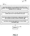
- FIG. 4 is a block diagram illustrating an example system 400 for improved uplink power management in a UE in accordance with some embodiments.
- system 400 may reside at least partially within a UE (e.g. UE 102 of FIG. 1 ), such as a UE or network entity (e.g. a network entity of PCell(s) 104 and/or SCell(s) 110 of FIG. 1 ).
- a UE e.g. UE 102 of FIG. 1
- network entity e.g. a network entity of PCell(s) 104 and/or SCell(s) 110 of FIG. 1
- system 400 is represented as including functional blocks, which may be functional blocks that represent functions implemented by a processor, software, or combination thereof (e.g. firmware).
- System 400 includes a logical grouping 402 of electrical modules that may act in conjunction.
- logical grouping 402 may include an electrical module 404 for determining whether a total desired transmission power exceeds a total configured maximum output power.
- electrical module 404 may comprise power comparison module 206 ( FIG. 2 ).
- logical grouping 402 may include an electrical module 406 for allocating a minimum proactive power limitation to each serving cell.
- electrical module 406 may comprise minimum proactive power allocating module 212 ( FIG. 2 ).
- logical grouping 402 may include an electrical module 408 for assigning a remaining power to one or more channels based on priority.
- electrical module 408 may comprise remaining power assigning module 226 ( FIG. 2 ).
- logical grouping 402 may include electrical module 410 for computing a total power assignment.
- electrical module 410 may comprise total power assignment computing module 234 ( FIG. 2 ).
- system 400 may include a memory 412 that retains instructions for executing functions associated with electrical modules 404, 406, 408, and 410, stores data used or obtained by electrical modules 404, 406, 408, and 410, etc. While shown as being external to memory 412, it is to be understood that one or more of electrical modules 404, 406, 408, and 410 may exist within memory 412. In one example, electrical modules 404, 406, 408, and 410 may comprise at least one processor, or each electrical module 404, 406, 408, and 410 may be a corresponding module or module of at least one processor. Moreover, in an additional or alternative example, one or more electrical modules 404, 406, 408, and 410 may be a computer program product including a computer readable medium, where the respective electrical module 404, 406, 408, and 410 may be corresponding code.
- FIG. 5 is a block diagram illustrating a machine in the example form of a computer system 500, within which a set or sequence of instructions for causing the machine to perform any one of the methodologies discussed herein may be executed, according to an example embodiment.
- the machine operates as a standalone device or may be connected (e.g. networked) to other machines.
- the machine may operate in the capacity of either a server or a client machine in server-client network environments, or it may act as a peer machine in peer-to-peer (or distributed) network environments.
- the machine may be a personal computer (PC), a tablet PC, a set-top box (STB), a Personal Digital Assistant (PDA), a mobile telephone, a web appliance, a network router, switch or bridge, or any machine capable of executing instructions (sequential or otherwise) that specify actions to be taken by that machine.
- PC personal computer
- PDA Personal Digital Assistant
- STB set-top box
- PDA Personal Digital Assistant
- mobile telephone a web appliance
- network router switch or bridge
- the storage device 515 includes a machine-readable medium 522 on which is stored one or more sets of data structures and instructions 524 (e.g. software) embodying or utilized by any one or more of the methodologies or functions described herein.
- the instructions 524 may also reside, completely or at least partially, within the main memory 504, static memory 505, and/or within the processor 502 during execution thereof by the computer system 500, with the main memory 504, static memory 505, and the processor 502 also constituting machine-readable media.
- machine-readable medium 522 is illustrated in an example embodiment to be a single medium, the term “machine-readable medium” may include a single medium or multiple media (e.g. a centralized or distributed database, and/or associated caches and servers) that store the one or more instructions 524.
- the term “machine-readable medium” shall also be taken to include any tangible medium that is capable of storing, encoding or carrying instructions for execution by the machine and that cause the machine to perform any one or more of the methodologies of the present disclosure or that is capable of storing, encoding or carrying data structures utilized by or associated with such instructions.
- the term “machine-readable medium” shall accordingly be taken to include, but not be limited to, solid-state memories, and optical and magnetic media.
- machine-readable media include nonvolatile memory, including, by way of example, semiconductor memory devices (e.g. Electrically Programmable Read-Only Memory (EPROM), Electrically Erasable Programmable Read-Only Memory (EEPROM)) and flash memory devices; magnetic disks such as internal hard disks and removable disks; magneto-optical disks; and CD-ROM and DVD-ROM disks.
- semiconductor memory devices e.g. Electrically Programmable Read-Only Memory (EPROM), Electrically Erasable Programmable Read-Only Memory (EEPROM)
- flash memory devices e.g. Electrically Programmable Read-Only Memory (EPROM), Electrically Erasable Programmable Read-Only Memory (EEPROM)
- EPROM Electrically Programmable Read-Only Memory
- EEPROM Electrically Erasable Programmable Read-Only Memory
- the instructions 524 may further be transmitted or received over a communications network 526 using a transmission medium via the network interface device 520 utilizing any one of a number of well-known transfer protocols (e.g. HTTP).
- Examples of communication networks include a local area network (LAN), a wide area network (WAN), the Internet, mobile telephone networks, Plain Old Telephone (POTS) networks, and wireless data networks (e.g. Wi-Fi, 3G, and 4G LTE/LTE-A or WiMAX networks).
- POTS Plain Old Telephone
- wireless data networks e.g. Wi-Fi, 3G, and 4G LTE/LTE-A or WiMAX networks.
- transmission medium shall be taken to include any intangible medium that is capable of storing, encoding, or carrying instructions for execution by the machine, and includes digital or analog communications signals or other intangible medium to facilitate communication of such software.
- Examples, as described herein, may include, or may operate on, logic or a number of modules, modules, or mechanisms.
- Modules are tangible entities capable of performing specified operations and may be configured or arranged in a certain manner.
- circuits may be arranged ( e.g. internally or with respect to external entities such as other circuits) in a specified manner as a module.
- the whole or part of one or more computer systems e.g. a standalone, client or server computer system
- one or more hardware processors may be configured by firmware or software (e.g. instructions, an application portion, or an application) as a module that operates to perform specified operations.
- the software may reside (1) on a non-transitory machine-readable medium or (2) in a transmission signal.
- the software when executed by the underlying hardware of the module, causes the hardware to perform the specified operations.
- Example 1 may include subject matter (such as an apparatus, mobile apparatus, user equipment, network device, communication apparatus or device, hardware, module, or module) comprising a power comparison module configured to determine whether a total desired transmission power exceeds a total configured maximum output power for a subframe, a minimum proactive power allocating module configured to allocate a minimum proactive power limitation to each serving cell, a remaining power assigning module configured to assign a remaining power to one or more channels based on priority, a total power assignment computing module configured to compute a total power assignment based on the allocating and the assigning.
- subject matter such as an apparatus, mobile apparatus, user equipment, network device, communication apparatus or device, hardware, module, or module
- a power comparison module configured to determine whether a total desired transmission power exceeds a total configured maximum output power for a subframe
- a minimum proactive power allocating module configured to allocate a minimum proactive power limitation to each serving cell
- a remaining power assigning module configured to assign a remaining power to one or more channels based on priority
- a total power assignment computing module
- Example 2 may include, or may optionally be combined with the subject matter of Example 1 to optionally include subject matter such that the minimum proactive power allocating module is further configured to assign at least a part of a physical uplink control channel (PUCCH) power as a first priority.
- PUCCH physical uplink control channel
- Example 3 may include, or may optionally combined with the subject matter of one or both of Examples 1 or 2 to optionally include subject matter such that the minimum proactive power allocating module is further configured to assign at least a part of a physical uplink shared channel (PUSCH) with downlink control information (DCI) power as a second priority.
- PUSCH physical uplink shared channel
- DCI downlink control information
- Example 4 may include, or may optionally combined with the subject matter of any of Examples 1-3 to optionally include subject matter such that the minimum proactive power allocating module is further configured to assign at least a part of a physical uplink shared channel without downlink control information power as a lowest priority.
- Example 6 may include, or may optionally combined with the subject matter of any of Examples 1-5 to optionally include subject matter such that the remaining power assigning module is further configured to assign a remaining physical uplink shared channel with downlink control information power as a second remaining power priority.
- Example 7 may include, or may optionally combined with the subject matter of any of Examples 1-6 to optionally include subject matter such that the remaining power assigning module is further configured to assign a remaining physical uplink shared channel without downlink control information power as a lowest remaining power priority.
- Example 2 may include, or may optionally be combined with the subject matter of Example 1 to optionally include a reset state determining module configured to determine whether a secure timer reset flag indicates a reset state, and a secure clock recovery procedure initiating module configured to initiate the secure clock recovery procedure where the secure timer reset flag indicates a reset state.
- a reset state determining module configured to determine whether a secure timer reset flag indicates a reset state
- a secure clock recovery procedure initiating module configured to initiate the secure clock recovery procedure where the secure timer reset flag indicates a reset state.
- Example 3 may include, or may optionally be combined with the subject matter of Examples 1 and/or 2 to optionally include a flag setting module configured to set the secure timer reset flag where secure timer reset occurs.
- Example 4 may include, or may optionally be combined with the subject matter of one or any combination of Examples 1 through 3 to optionally include a resynchronization requesting module configured to request a timer resynchronization message from a network entity.
- Example 5 may include, or may optionally be combined with the subject matter of one or any combination of Examples 1 through 4 to optionally include a message receiving module configured to receive a timer resynchronization message from a network entity.
- Example 6 may include, or may optionally be combined with the subject matter of one or any combination of Examples 1 through 5, wherein the timer resynchronization message is integrity protected.
- Example 7 may include, or may optionally be combined with the subject matter of one or any combination of Examples 1 through 6, wherein the reset delta obtaining module is further configured to obtain the reset delta by subtracting the second secure clock time and the timer offset from the second network time.
- Example 8 may include subject matter (such as a method, means for performing acts, machine readable medium including instructions that, when performed by a machine cause the machine to performs acts, or an apparatus configured to perform), which may optionally be in addition to any one or combination of Examples 1-7, comprising determining whether a total desired transmission power exceeds a total configured maximum output power for a subframe, and where the total desired transmission power exceeds the total configured maximum output power, further comprises: allocating a minimum proactive power limitation to each serving cell, assigning a remaining power to one or more channels based on priority, computing a total power assignment based on the allocating and the assigning.
- subject matter such as a method, means for performing acts, machine readable medium including instructions that, when performed by a machine cause the machine to performs acts, or an apparatus configured to perform
- Example 9 may include, or may optionally be combined with the subject matter of any of Examples 1-8 to optionally include assigning at least a part of a physical uplink control channel power as a first priority.
- Example 11 may include, or may optionally be combined with the subject matter of Examples 1-10 to optionally include assigning at least a part of a physical uplink shared channel without downlink control information power as a lowest priority.
- Example 12 may include, or may optionally be combined with the subject matter of Examples 1-11 to optionally include assigning a remaining physical uplink control channel power as a first remaining power priority.
- Example 14 may include, or may optionally be combined with the subject matter of Examples 1-13 to optionally include assigning a remaining physical uplink shared channel without downlink control information power as a lowest remaining power priority.
Abstract
processing circuitry; and transceiver circuitry configured to: receive signaling from a primary cell group (CG1) associated with a master eNB (MeNB), the signaling to configure the UE with a secondary cell group (CG2) for dual connectivity, the CG2 associated with a secondary eNB (SeNB); receive scheduling information, from the MeNB, for a scheduled uplink transmission in the CG1; receive scheduling information, from the SeNB, for a scheduled uplink transmission in the CG2; allocate a minimum power for the scheduled uplink transmission in the CG2 before allocating at least some remaining power to the scheduled uplink transmission in the CG1 if the scheduled uplink transmission in the CG2 includes control information and if the scheduled uplink transmission in the CG2 is determined to overlap in time with the scheduled uplink transmission in the CG1; and transmit the scheduled uplink transmission in the CG2 and the scheduled uplink transmission in the CG1 in accordance with respective power allocations.
Description
- This application claims the benefit of priority to
U.S. Patent Application Serial No. 13/971,971, filed on August 21, 2013 - Embodiments described herein pertain generally to wireless communications and in particular to methods and apparatus for uplink power control enhancement in Long-Term Evolution Advanced (LTE-A, LTE-Advanced) communications environments.
- Mobile devices (e.g. user equipment (UE)) in heterogeneous network environments, such as LTE-Advanced network environments, may simultaneously communicate with multiple access points, which may include a primary access point, or PCell, and one or more secondary access points, or SCells. In some systems, a macro cell may serve as the PCell, the primary access point governing mobility and other control processes, and one or more SCells (small cells or other macro cells) may serve as the one or more secondary access points that are utilized for data offloading. In such example systems, the maximum transmission power for a mobile device in a subframe can be easily reached by transmitting control messages to the PCell, leaving little to no power for data transmission to the SCells. Thus, there is a need for improved power allocation management in heterogeneous network environments.
-
-
FIG. 1 is a system diagram illustrating an LTE-Advanced wireless system in accordance with some embodiments; -
FIG. 2 is a block diagram illustrating an example UE including uplink power manager in accordance with some embodiments; -
FIG. 3 is a flowchart illustrating a method for improved uplink power management in UEs in accordance with some embodiments; -
FIG. 4 is a block diagram illustrating an example system for improved uplink power management in a UE in accordance with some embodiments; and -
FIG. 5 is a block diagram illustrating a machine in the example form of a computer system, within which a set or sequence of instructions for causing the machine to perform any one of the methodologies discussed herein may be executed in accordance with some embodiments. - The present disclosure presents example methods and apparatuses for improved uplink power control in LTE-Advanced wireless environments, wherein a UE may communicate with multiple cells, including a PCell and one or more SCells, over multiple component carriers using carrier aggregation (CA). In such environments, some examples of the improved uplink power control methods and apparatuses described herein may be based on a power allocation tradeoff strategy using a Minimum Proactive Power Limitation (MPLL) per component carrier, PCMIN,c . In an aspect, if the total transmit power of a UE in a subframe i over all cells and all component carriers would exceed a linear value of a configured maximum output power P̂CMAX (i), the UE may assign PCMIN,c, first to each serving cell c in subframe i, and the remaining power would be assigned to uplink channels, whether PCell or SCell channels, or control or data channels, based on priority. In some examples, this priority may be given first to a physical uplink control channel (PUCCH) (e.g. uplink channel to the primary macro cell, or PCell), then to a physical uplink shared channel
- (PUSCH) with downlink control information (DCI) (e.g. an uplink channel to the primary macro cell), and then to a PUSCH without DCI (e.g. an uplink channel to one or more SCells. This prioritization allows UEs in LTE-Advanced environments to offload data uplink transmissions to SCells (e.g. via PUSCH) while ensuring that necessary control signaling with the PCell remains intact in the uplink (e.g. via PUCCH), even in a restrictive UE power condition.
-
FIG. 1 is a system diagram illustrating an LTE-Advanced wireless system in accordance with some embodiments.FIG. 1 includes an example UE 102, which may communicate wirelessly with a PCell 104 over awireless communication link 108. In an aspect,communication link 108 may include one or more communication channels, which may include a PUCCH, a PUSCH with DCI transmitted on the downlink (or DCI not transmitted on the downlink), and any other channel for transmitting control (e.g. scheduling or power) information or data on the uplink or downlink. Becausesystem 100 may support carrier aggregation (e.g. may be an LTE-A system) these channels may be comprised of one or more component carriers that may be aggregated. - Furthermore, PCell 104 may be a cell associated with a macro network, such as, but not limited to, a radio access network or cellular network. For example, in some examples, PCell 104 may comprise a PCell in LTE-Advanced communication environments. In a further aspect, PCell 104 of
FIG. 1 may be associated with aPCell network entity 106, which may comprise or include one or more of any type of network module, such as an access point, a macro cell, including a base station (BS), node B, eNodeB (eNB), a relay, a peer-to-peer device, an authentication, authorization and accounting (AAA) server, a mobile switching center (MSC), a radio network controller (RNC). Additionally, the network entity associated with PCell 104 may communicate with one or more other network entities of wireless and/or core networks, such as, but not limited to, wide-area networks (WAN), wireless networks (e.g. 802.11 or cellular network), the Public Switched Telephone Network (PSTN) network, ad hoc networks, personal area networks (e.g. Bluetooth®) or other combinations or permutations of network protocols and network types. Such network(s) may include a single local area network (LAN) or wide-area network (WAN), or combinations of LANs or WANs, such as the Internet. - In an aspect, the UE 102 may be a mobile device, such as, but not limited to, a smartphone, cellular telephone, mobile phone, laptop computer, tablet computer, or other portable networked device. In addition, UE 102 may also be referred to by those skilled in the art as a mobile station, a subscriber station, a mobile unit, a subscriber unit, a wireless unit, a remote unit, a mobile device, a wireless device, a wireless communications device, a remote device, a mobile subscriber station, an access terminal, a mobile terminal, a wireless terminal, a remote terminal, a handset, a terminal, a user agent, a mobile client, a client, or some other suitable terminology. In general, UE 102 may be small and light enough to be considered portable. Furthermore, UE 102 may include an
uplink power manager 204, which may be configured to manage the transmission power of uplink transmissions associated with UE 102. - In a further aspect, UE 102 may communicate with one or more SCells 110 (dotted line indicating that a plurality of SCells is optional) via one or
more communication links 112. In some examples, the one ormore SCells 110 may include SCells in LTE-Advanced communication environments. In an aspect, UE 102 may be configured to communicate simultaneously with PCell 104 and the one or more SCells 110, for example, via a plurality of antennas of UE 102. In an aspect,communication link 108 may include one or more communication channels, which may include a PUCCH, a PUSCH with DCI transmitted on the downlink (or DCI not transmitted on the downlink), and any other channel for transmitting control (e.g. scheduling or power) information or data on the uplink or downlink. - In an aspect, SCells 110 may be small cells or low power cells, controlled by or otherwise associated with one or more network entities or modules, such as, but not limited to a low-power access point, such as a picocell, femtocell, microcell, WiFi hotspot, etc. Additionally, SCells 110 may communicate with one or more other network entities of wireless and/or core networks, such as, but not limited to, wide-area networks (WAN), wireless networks (e.g. 802.11 or cellular network), the Public Switched Telephone Network (PSTN) network, ad hoc networks, personal area networks (e.g. Bluetooth®) or other combinations or permutations of network protocols and network types. Such network(s) may include a single local area network (LAN) or wide-area network (WAN), or combinations of LANs or WANs, such as the Internet.
- Additionally,
system 100, which may include PCell 104 and one ormore SCells 110, may comprise a Wideband Code Division Multiple Access (W-CDMA) system, and PCell 104 and one or more SCells 110 may communicate with one ormore UEs 102 according to this standard. As those skilled in the art will readily appreciate, various aspects described throughout this disclosure may be extended to other telecommunication systems, network architectures and communication standards. By way of example, various aspects may be extended to other Universal Mobile Telecommunications System (UMTS) systems such as Time Division Synchronous Code Division Multiple Access (TD-SCDMA), High Speed Downlink Packet Access (HSDPA), High Speed Uplink Packet Access (HSUPA), High Speed Packet Access Plus (HSPA+) and Time-Division CDMA (TD-CDMA). Various aspects may also be extended to systems employing Long Term Evolution (LTE) (in FDD, TDD, or both modes), LTE-Advanced (LTE-A) (in FDD, TDD, or both modes), CDMA2000, Evolution-Data Optimized (EV-DO), Ultra Mobile Broadband (UMB), Institute of Electrical and Electronics Engineers (IEEE) 802.11 (Wi-Fi), IEEE 802.16 (WiMAX®), IEEE 802.20, Ultra-Wideband (UWB), Bluetooth, and/or other suitable systems. The actual telecommunication standard, network architecture, and/or communication standard employed will depend on the specific application and the overall design constraints imposed on the system. The various devices coupled to the network(s) (e.g. UE 102 and/or network entities serving PCell 104 and/or SCells 110) may be coupled to the network(s) via one or more wired or wireless connections. - In example embodiments, the UE 102 may comprise processing circuitry arranged to determine whether a total desired transmission power over a plurality of channels exceeds a total configured maximum output power for a subframe when the UE is scheduled for concurrent physical uplink control channel (PUCCH) and physical uplink shared channel (PUSCH) transmission by an enhanced node B (eNB) in the subframe. The processing circuitry may also be arranged to initially allocate a minimum proactive power to the channels. The processing circuitry may also be arranged to initially allocate any remaining power of a power budget to the channels based on priority. The UE 102 may also include a transceiver configured by the processing circuitry to transmit the channels in accordance the minimum proactive power and the remaining power allocations. In these embodiments, the PUCCH of a primary cell (PCell) is allocated power as a first priority, a physical uplink shared channel (PUSCH) with downlink control information (DCI) of the PCell is allocated power as a second priority, and the PUSCH without DCI of a secondary cell (SCell) is allocated power as a lowest priority.
- In some embodiments, the processing circuitry may also compute the total power assignment from the minimum proactive power and the remaining power allocations. In Some embodiments, the processing circuitry may also initially allocate the minimum proactive power to the channels based on the priorities.
-
FIG. 2 is a block diagram illustrating an example UE including uplink power manager in accordance with some embodiments, which may be configured to manage uplink power allocation associated with a UE (e.g. UE 102 ofFIG. 1 ). In an aspect,uplink power manager 204 may include apower comparison module 206, which may be configured to compare power values to determine whether a total desiredtransmission power 208 of the UE for a particular subframe i exceeds a total configured maximum output power 210 (represented herein as P̂CMAX (i)), for the subframe. In some examples, the total desiredtransmission power 208 of the UE may include the sum of multiple module transmission powers, which may include, but are not limited to: the sum of uplink PUSCH channel transmission powers to each serving cell in subframe i (represented herein as
power comparison module 206 may be configured to evaluate one or both of the following inequalities:

- In addition,
uplink power manager 204 may include a minimum proactivepower allocating module 212, which may be configured to allocate a minimum proactive power, PCMIN,c, to one or more uplink channels wherepower comparison module 206 determines that the total desired transmission power exceeds the total configured maximum output power. In an aspect, minimumproactive power module 212 may include a minimum proactivepower computing module 214, which may be configured to compute one or more minimum proactive power values corresponding to each serving channel c, PCMIN,c , which may be allocated to one or more uplink channels associated with a UE. In a non-limiting aspect, PCMIN,c may be allocated to one or more uplink channels to ensure a non-zero uplink power allocation to each such channel. Furthermore, in an aspect, the minimum proactive power PCMIN,c can be computed such that, when allocated and applied, it may have a minor impact to total power limitation. In one such non-limiting example, where the total power limitation is 23dBm, the PCMIN,c can be set to affect a maximum 0.5 dB degradation to the 23dBm total power limitation (e.g. (10^(23/10)) - (10^(22.5/10)) = 21.7 mw = 13.3 dBm). In another non-limiting aspect, the minimum proactive power PCMIN,c can be set as the uplink power to meet the coverage of a small cell, and may comprise one value among a set of potential configurable values (e.g. 0dBm, 10dBm). In an additional aspect, this value can be configurable for network optimization adjustment purposes. - In an additional aspect, minimum proactive
power allocating module 212 may allocate the minimum proactive power individually to two or more channels based on priority. This priority may conform to the power priority definition of existing standards, including, but not limited to standards promulgated by the Third Generation Partnership Project (3GPP), for example, in 3GPP TS 36.213 "E-UTRA, Physical Layer Procedures," V10.6.0 and 3GPP TS 36.101 "Evolved Universal Terrestrial Radio Access (E-UTRA); User Equipment (UE) Radio Transmission and Reception," which are hereby incorporated by reference. For example, in an aspect, the uplink transmission power priority exercised by minimum proactivepower allocating module 212 may allocate PCMIN,c to uplink channels according to the following priority:
- As such, minimum proactive power allocating module may include a PUCCH
power allocating module 214, which may be configured to allocate a portion of the limited uplink power budget of the UE as a first part of a PUCCH power as first priority. In a non-limiting example aspect, this first part of the PUCCH power may be allocated as a function of PCMIN,c in subframe i according to the following equation:
PCell 104 ofFIG. 1 ) for subframe i; and P̂ CMAX,c (i) represents the linear value of P CMAX,c (i), which may be defined by the requirements of a standard (e.g. 3GPP TS 36.101 "Evolved Universal Terrestrial Radio Access (E-UTRA); User Equipment (UE) Radio Transmission and Reception"). - Additionally,
uplink power manager 204 may include a remainingpower calculating module 222, which may be configured to calculate a linear value of a remaining power, represented herein as P̂REMAINING (i), of a limited uplink power budget for the uplink subframe i after a module of the minimum proactivepower allocating module 212 allocates uplink power to one or more channels. For example, in an aspect, after PUCCHpower allocating module 216 allocates P̂ PUCCH_Part1 according to Equation (3), remainingpower calculating module 222 may calculate P̂REMAINING (i) according to the following algorithm:
- Based on this P̂ REMAINING(i), the minimum proactive power allocating module may then allocate remaining uplink power to other channels. For example, minimum proactive
power allocating module 212 may include a PUSCH with DCI power allocating module 218, which may be configured to allocate uplink power to a PUSCH channel with DCI in the downlink (e.g. a channel for data communication with the PCell, which may be a macro cell) as a second priority. In an aspect, PUSCH with DCI power allocating module 218 may allocate a first part of such a PUSCH with DCI channel uplink power based on the following equation:
- In addition, once the P̂ PUSCHw/DCI_Part1 value has been calculated by PUSCH with DCI power allocating module 218, remaining
power calculating module 222 may update the remainingpower 224 value, as more available power for the subframe has been allocated to the PUSCH with DCI channel(s). In an aspect, remainingpower calculating module 222 may do so according to the following equation:
power 224 after the updating. - Additionally, minimum proactive
power allocating module 212 may include a PUSCH without DCI power allocating module 220, which may be configured to allocate uplink power to one or more PUSCH channels that do not transport DCI information on the downlink. In an aspect, such channels may facilitate communication between a UE and a SCell, which may be a small cell, though the present disclosure is not limited to such a scenario. Further, PUSCH without DCI power allocating module 220 may be configured to allocate remaining uplink power to such a channel as a lowest priority, or third priority, of the PUCCH, PUSCH with DCI, and PUSCH without DCI channels. For example, PUSCH without DCI power allocating module 220 may be configured to allocate a first part of a PUSCH without DCI power, P̂ PUSCHw/oDCI_Part1, according to the following algorithm:
- In addition, once the P̂ PUSCHw/loDCI_Part1 value has been calculated by PUSCH without DCI power allocating module 220, remaining
power calculating module 222 may update the remainingpower 224 value, as more available power for the subframe has been allocated to a first part of the PUSCH without DCI channel(s). In an aspect, remainingpower calculating module 222 may do so according to the following equation:
power 224 after the updating. - In addition,
uplink power manager 204 may include a remainingpower assigning module 226, which may be configured to assign remaining uplink power to one or more channels after an initial power allocation, which may be performed by minimum proactivepower allocating module 212. In an aspect, remainingpower assigning module 226 may include a remaining PUCCHpower assigning module 228, which may be configured to assign a second part of a PUCCH power, P̂ PUCCHPart2, to the PUCCH, for example, where the first part of the PUCCH uplink transmission power, P̂ PUCCH_Part1, is less than the standard-allocated maximum PUCCH power, P̂PUCCH (i), for subframe i. In other words, remaining PUCCHpower assigning module 228 may be configured to evaluate the inequality: P̂ PUCCH_Part1 < P̂PUCCH (i). Where this inequality is true, remaining PUCCHpower assigning module 228 may be configured to set P̂ PUCCH_Part2 according to the following equation:
- Additionally, once the P̂ PUCCH_Part2 value has been calculated by remaining PUCCH
power assigning module 228, remainingpower calculating module 222 may update the remainingpower 224 value, as more available power for the subframe has been allocated to the second part of the PUCCH channel(s). In an aspect, remainingpower calculating module 222 may do so according to the following equation:
- In a further aspect, remaining
power assigning module 226 may include a remaining PUSCH with DCI power assigning module 230, which may be configured to assign a second part of a PUSCH with DCI uplink transmission power, P̂ PUSCHw/DCI_Part2, to the PUSCH with DCI channel(s) as a second priority. Remaining PUSCH with DCI power assigning module 230 may be configured to do so, for example, where the first part of the PUSCH with DCI uplink transmission power, P̂ PUSCHw/DCI_Part1, is less than the standard-allocated maximum PUSCH with DCI per-channel power, P̂ PUSCHw/DCI,c (i), for subframe i and cell c. In other words, remaining PUSCH with DCI power assigning module 230 may be configured to evaluate the inequality: P̂ PUSCHw/DCI_Part1 < P̂ PUSCHwe/IDCI,c (i). Where this inequality is true, remaining PUSCH with DCI power assigning module 230 may be configured to set P̂ PUSCHw/DCI_Part2 according to the following equation:
- Additionally, once the P̂ PUSCHw/DCI_Part2 value has been calculated by remaining PUSCH with DCI power assigning module 230, remaining
power calculating module 222 may update the remainingpower 224 value, as more available power for the subframe has been allocated to the second part of the PUSCH with DCI channel(s). In an aspect, remainingpower calculating module 222 may do so according to the following equation:
- Moreover, remaining
power assigning module 226 may include a remaining PUSCH without DCI power assigning module 232, which may be configured to assign a second part of a PUSCH without DCI uplink transmission power, P̂ PUSCHw/oDCI_Part2, to the PUSCH without DCI channel(s) as a third (or least) priority. Remaining PUSCH without DCI power assigning module 232 may be configured to do so, for example, where the first part of the PUSCH without DCI uplink transmission power, P̂ PUSCHw/oDCI_Part1, is less than the standard-allocated maximum PUSCH without DCI per-channel power, P̂ PUSCHw/DCI,c (i), for subframe i and cell c. In other words, remaining PUSCH without DCI power assigning module 232 may be configured to evaluate the inequality: P̂ PUSCHw/oDCI_Part1 < P̂ PUSCHw/oDCI,c (i). Where this inequality is true, remaining PUSCH without DCI power assigning module 232 may be configured to set P̂ PUSCHw/oDCI_Part2 according to the following equation: (13) P̂ PUSCHw/oDCI_Part2 = min(P̂REMAINING (i),P̂CMAX,c (i),P̂ PUSCHw/oDCI,c(i) - P̂ PUSCHw/oDCI_Part1 (i), 0) - Additionally, once the P̂ PUSCHw/oDCI_Part2 value has been calculated by remaining PUSCH without DCI power assigning module 232, remaining
power calculating module 222 may update the remainingpower 224 value, as more available power for the subframe has been allocated to the second part of the PUSCH without DCI channel(s). In an aspect, remainingpower calculating module 222 may do so according to the following equation:
- Additionally,
uplink power manager 204 may include a total powerassignment computing module 234, which may be configured to compute a total power assignment for each uplink channel scheduled to transmit uplink data in a subframe. In an aspect, total powerassignment computing module 234 may be configured to compute these total power assignments by combining and/or summing component (e.g. Part 1, Part 2, and so on) power allocation or assignment values for one or more channels, which may have been assigned, allocated, and/or stored by one or more other modules of uplink power manager 204-such as, but not limited to, minimum proactivepower allocating module 212 and/or remainingpower assigning module 226. - For example, in an aspect, total power
assignment computing module 234 may be configured to compute a total PUCCH uplink assignment value, - P̂PUCCH_TOTAL, for subframe i according to the following equation:

- Likewise, total power
assignment computing module 234 may be configured to compute a total PUSCH with DCI uplink assignment value, - P̂ PUSCHw/DCI_TOTAL , for subframe i and for each channel c according to the following equation:

- Furthermore, total power
assignment computing module 234 may be configured to compute a total PUSCH without DCI uplink assignment value, P̂ PUSCHw/oDCI_TOTAL , for subframe i and for each channel c according to the following equation:
-
FIG. 3 is a flowchart illustrating amethod 300 for improved uplink transmission power management, according to some example embodiments. In some examples,method 300 and/or any of the methodsteps comprising method 300 may be configured to be performed by a processing apparatus, which may includeUE 102 ofFIG. 1 , a network device (e.g. a network entity of primary or SCells ofFIG. 1 ) and/or a method therein, for example. In some examples,method 300 may be performed during transmission scheduling procedures for each uplink transmission subframe i of a plurality of transmission subframes in a slot, frame, block, or any other transmission window, slot, or other temporal or wavelength transmission-organizing mechanism or procedure. - In an aspect,
method 300 may include a decision atblock 302, wherein the processing apparatus may determine whether a total desired transmission power exceeds a total configured maximum output power. Where the total desired transmission power does not exceed the total configured maximum output power (NO decision line),method 300 may proceed to end and the uplink power scheduling may proceed as normal (e.g. according to specification-defined uplink power methods and values). However, where the total desired transmission power exceeds the total configured maximum output power (YES decision line),method 300 may proceed to block 304. - In an aspect, at
block 304, a processing apparatus may allocate a minimum proactive power limitation to each serving cell. In an aspect, the minimum proactive power limitation may be based on a minimum proactive power value, PCMIN,c. In a non-limiting aspect, PCMIN,c may be allocated to one or more uplink channels to ensure a non-zero uplink power allocation to each such channel. Furthermore, in an aspect, the minimum proactive power PCMIN,c can be computed such that, when allocated and applied, it may have a minor impact to total power limitation. In another non-limiting aspect, the minimum proactive power PCMIN,c can be set as the uplink power to meet the coverage of a small cell, and may comprise one value among a set of potential configurable values (e.g. 0dBm, 10dBm). Furthermore, allocating the minimum proactive power limitation to each serving cell may comprise allocating a first part of total power assignment in the uplink for a particular cell for a subframe i. In an additional aspect, this value can be configurable for network optimization adjustment purposes. - In addition, at
block 304, the minimum proactive power limitation value may be allocated based on priority, such as, but not limited to, a priority scheme that takes the form of PUCCH > PUSCH (with DCI) > PUSCH (without DCI), as described in reference toFIG. 2 above. Furthermore, the allocation of the minimum proactive power limitation may be performed according to the methods, equations, or techniques performed by minimum proactivepower allocating module 212, remainingpower calculating module 222, and/or any of the modules therein (seeFIG. 2 ). - In addition, at
block 306, a processing apparatus may assign remaining power to one or more channels based on priority. In an aspect, the assigning ofblock 306 may comprise a second part of a total transmission power for one or more uplink channels. As with the allocation atblock 304, the remaining power may be assigned to one or more channels based on priority, such as, but not limited to, a priority scheme that takes the form of PUCCH > PUSCH (with DCI) > PUSCH (without DCI), as described in reference toFIG. 2 above. Moreover, the allocation of the minimum proactive power limitation may be performed according to the methods, equations, or techniques performed by remainingpower assigning module 226, remainingpower calculating module 222, and/or any of the modules therein (seeFIG. 2 ). - In addition, at
block 308, a processing apparatus may compute a total power assignment based on the allocating and assigning ofblocks block 308, the processing apparatus may compute total power assignments by combining and/or summing component (e.g. Part 1, Part 2, and so on) power allocation or assignment values for one or more channels, which may have been assigned, allocated, and/or stored atblocks 304 and/or 306 ofmethod 300. Additionally, once these total power assignments are computed atblock 308, thepower allocation method 300 may end and the processing apparatus may transmit one or more messages via one or more channels according to the channels' unique total power assignments allocated or otherwise computed bymethod 300. -
FIG. 4 is a block diagram illustrating anexample system 400 for improved uplink power management in a UE in accordance with some embodiments. For example,system 400 may reside at least partially within a UE (e.g. UE 102 ofFIG. 1 ), such as a UE or network entity (e.g. a network entity of PCell(s) 104 and/or SCell(s) 110 ofFIG. 1 ). It is to be appreciated thatsystem 400 is represented as including functional blocks, which may be functional blocks that represent functions implemented by a processor, software, or combination thereof (e.g. firmware).System 400 includes alogical grouping 402 of electrical modules that may act in conjunction. - For instance,
logical grouping 402 may include an electrical module 404 for determining whether a total desired transmission power exceeds a total configured maximum output power. In an aspect, electrical module 404 may comprise power comparison module 206 (FIG. 2 ). Additionally,logical grouping 402 may include anelectrical module 406 for allocating a minimum proactive power limitation to each serving cell. In an aspect,electrical module 406 may comprise minimum proactive power allocating module 212 (FIG. 2 ). In an additional aspect,logical grouping 402 may include anelectrical module 408 for assigning a remaining power to one or more channels based on priority. In an aspect,electrical module 408 may comprise remaining power assigning module 226 (FIG. 2 ). Furthermore,logical grouping 402 may includeelectrical module 410 for computing a total power assignment. In an aspect,electrical module 410 may comprise total power assignment computing module 234 (FIG. 2 ). - Additionally,
system 400 may include amemory 412 that retains instructions for executing functions associated withelectrical modules electrical modules memory 412, it is to be understood that one or more ofelectrical modules memory 412. In one example,electrical modules electrical module electrical modules electrical module -
FIG. 5 is a block diagram illustrating a machine in the example form of acomputer system 500, within which a set or sequence of instructions for causing the machine to perform any one of the methodologies discussed herein may be executed, according to an example embodiment. In alternative embodiments, the machine operates as a standalone device or may be connected (e.g. networked) to other machines. In a networked deployment, the machine may operate in the capacity of either a server or a client machine in server-client network environments, or it may act as a peer machine in peer-to-peer (or distributed) network environments. The machine may be a personal computer (PC), a tablet PC, a set-top box (STB), a Personal Digital Assistant (PDA), a mobile telephone, a web appliance, a network router, switch or bridge, or any machine capable of executing instructions (sequential or otherwise) that specify actions to be taken by that machine. Further, while only a single machine is illustrated, the term "machine" shall also be taken to include any collection of machines that individually or jointly execute a set (or multiple sets) of instructions to perform any one or more of the methodologies discussed herein. -
Example computer system 500 includes at least one processor 502 (e.g. a central processing unit (CPU), a graphics processing unit (GPU) or both, processor cores, compute nodes, etc.), amain memory 504 and a static memory 505, which communicate with each other via a link 508 (e.g. bus). Thecomputer system 500 may further include avideo display unit 510, an alphanumeric input device 512 (e.g. a keyboard), and a user interface (UI) navigation device 514 (e.g. a mouse). In one embodiment, thevideo display unit 510,input device 512 andUI navigation device 514 are incorporated into a touch screen display. Thecomputer system 500 may additionally include a storage device 515 (e.g. a drive unit), a signal generation device 518 (e.g. a speaker), anetwork interface device 520, and one or more sensors (not shown), such as a global positioning system (GPS) sensor, compass, accelerometer, or other sensor. - The storage device 515 includes a machine-
readable medium 522 on which is stored one or more sets of data structures and instructions 524 (e.g. software) embodying or utilized by any one or more of the methodologies or functions described herein. Theinstructions 524 may also reside, completely or at least partially, within themain memory 504, static memory 505, and/or within theprocessor 502 during execution thereof by thecomputer system 500, with themain memory 504, static memory 505, and theprocessor 502 also constituting machine-readable media. - While the machine-
readable medium 522 is illustrated in an example embodiment to be a single medium, the term "machine-readable medium" may include a single medium or multiple media (e.g. a centralized or distributed database, and/or associated caches and servers) that store the one ormore instructions 524. The term "machine-readable medium" shall also be taken to include any tangible medium that is capable of storing, encoding or carrying instructions for execution by the machine and that cause the machine to perform any one or more of the methodologies of the present disclosure or that is capable of storing, encoding or carrying data structures utilized by or associated with such instructions. The term "machine-readable medium" shall accordingly be taken to include, but not be limited to, solid-state memories, and optical and magnetic media. Specific examples of machine-readable media include nonvolatile memory, including, by way of example, semiconductor memory devices (e.g. Electrically Programmable Read-Only Memory (EPROM), Electrically Erasable Programmable Read-Only Memory (EEPROM)) and flash memory devices; magnetic disks such as internal hard disks and removable disks; magneto-optical disks; and CD-ROM and DVD-ROM disks. - The
instructions 524 may further be transmitted or received over acommunications network 526 using a transmission medium via thenetwork interface device 520 utilizing any one of a number of well-known transfer protocols (e.g. HTTP). Examples of communication networks include a local area network (LAN), a wide area network (WAN), the Internet, mobile telephone networks, Plain Old Telephone (POTS) networks, and wireless data networks (e.g. Wi-Fi, 3G, and 4G LTE/LTE-A or WiMAX networks). The term "transmission medium" shall be taken to include any intangible medium that is capable of storing, encoding, or carrying instructions for execution by the machine, and includes digital or analog communications signals or other intangible medium to facilitate communication of such software. - Examples, as described herein, may include, or may operate on, logic or a number of modules, modules, or mechanisms. Modules are tangible entities capable of performing specified operations and may be configured or arranged in a certain manner. In an example, circuits may be arranged (e.g. internally or with respect to external entities such as other circuits) in a specified manner as a module. In an example, the whole or part of one or more computer systems (e.g. a standalone, client or server computer system) or one or more hardware processors may be configured by firmware or software (e.g. instructions, an application portion, or an application) as a module that operates to perform specified operations. In an example, the software may reside (1) on a non-transitory machine-readable medium or (2) in a transmission signal. In an example, the software, when executed by the underlying hardware of the module, causes the hardware to perform the specified operations.
- Accordingly, the terms "module" and "module" are understood to encompass a tangible entity, be that an entity that is physically constructed, specifically configured (e.g. hardwired), or temporarily (e.g. transitorily) configured (e.g. programmed) to operate in a specified manner or to perform part or all of any operation described herein. Considering examples in which modules are temporarily configured, one instantiation of a module may not exist simultaneously with another instantiation of the same or different module. For example, where the modules comprise a general-purpose hardware processor configured using software, the general-purpose hardware processor may be configured as respective different modules at different times. Accordingly, software may configure a hardware processor, for example, to constitute a particular module at one instance of time and to constitute a different module at a different instance of time.
- Additional examples of the presently described method, system, and device embodiments include the following, non-limiting configurations. Each of the following non-limiting examples may stand on its own, or may be combined in any permutation or combination with any one or more of the other examples provided below or throughout the present disclosure. The preceding description and the drawings sufficiently illustrate specific embodiments to enable those skilled in the art to practice them. Other embodiments may incorporate structural, logical, electrical, process, and other changes. Portions and features of some embodiments may be included in, or substituted for, those of other embodiments.
- Example 1 may include subject matter (such as an apparatus, mobile apparatus, user equipment, network device, communication apparatus or device, hardware, module, or module) comprising a power comparison module configured to determine whether a total desired transmission power exceeds a total configured maximum output power for a subframe, a minimum proactive power allocating module configured to allocate a minimum proactive power limitation to each serving cell, a remaining power assigning module configured to assign a remaining power to one or more channels based on priority, a total power assignment computing module configured to compute a total power assignment based on the allocating and the assigning.
- Example 2 may include, or may optionally be combined with the subject matter of Example 1 to optionally include subject matter such that the minimum proactive power allocating module is further configured to assign at least a part of a physical uplink control channel (PUCCH) power as a first priority.
- Example 3 may include, or may optionally combined with the subject matter of one or both of Examples 1 or 2 to optionally include subject matter such that the minimum proactive power allocating module is further configured to assign at least a part of a physical uplink shared channel (PUSCH) with downlink control information (DCI) power as a second priority.
- Example 4 may include, or may optionally combined with the subject matter of any of Examples 1-3 to optionally include subject matter such that the minimum proactive power allocating module is further configured to assign at least a part of a physical uplink shared channel without downlink control information power as a lowest priority.
- Example 5 may include, or may optionally combined with the subject matter of any of Examples 1-4 to optionally include subject matter such that the remaining power assigning module is further configured to assign a remaining physical uplink control channel power as a first remaining power priority.
- Example 6 may include, or may optionally combined with the subject matter of any of Examples 1-5 to optionally include subject matter such that the remaining power assigning module is further configured to assign a remaining physical uplink shared channel with downlink control information power as a second remaining power priority.
- Example 7 may include, or may optionally combined with the subject matter of any of Examples 1-6 to optionally include subject matter such that the remaining power assigning module is further configured to assign a remaining physical uplink shared channel without downlink control information power as a lowest remaining power priority.
- Example 2 may include, or may optionally be combined with the subject matter of Example 1 to optionally include a reset state determining module configured to determine whether a secure timer reset flag indicates a reset state, and a secure clock recovery procedure initiating module configured to initiate the secure clock recovery procedure where the secure timer reset flag indicates a reset state.
- Example 3 may include, or may optionally be combined with the subject matter of Examples 1 and/or 2 to optionally include a flag setting module configured to set the secure timer reset flag where secure timer reset occurs.
- Example 4 may include, or may optionally be combined with the subject matter of one or any combination of Examples 1 through 3 to optionally include a resynchronization requesting module configured to request a timer resynchronization message from a network entity.
- Example 5 may include, or may optionally be combined with the subject matter of one or any combination of Examples 1 through 4 to optionally include a message receiving module configured to receive a timer resynchronization message from a network entity.
- Example 6 may include, or may optionally be combined with the subject matter of one or any combination of Examples 1 through 5, wherein the timer resynchronization message is integrity protected.
- Example 7 may include, or may optionally be combined with the subject matter of one or any combination of Examples 1 through 6, wherein the reset delta obtaining module is further configured to obtain the reset delta by subtracting the second secure clock time and the timer offset from the second network time.
- Example 8 may include subject matter (such as a method, means for performing acts, machine readable medium including instructions that, when performed by a machine cause the machine to performs acts, or an apparatus configured to perform), which may optionally be in addition to any one or combination of Examples 1-7, comprising determining whether a total desired transmission power exceeds a total configured maximum output power for a subframe, and where the total desired transmission power exceeds the total configured maximum output power, further comprises: allocating a minimum proactive power limitation to each serving cell, assigning a remaining power to one or more channels based on priority, computing a total power assignment based on the allocating and the assigning.
- Example 9 may include, or may optionally be combined with the subject matter of any of Examples 1-8 to optionally include assigning at least a part of a physical uplink control channel power as a first priority.
- Example 10 may include, or may optionally be combined with the subject matter of Examples 1-9 to optionally include assigning at least a part of a physical uplink shared channel with downlink control information power as a second priority.
- Example 11 may include, or may optionally be combined with the subject matter of Examples 1-10 to optionally include assigning at least a part of a physical uplink shared channel without downlink control information power as a lowest priority.
- Example 12 may include, or may optionally be combined with the subject matter of Examples 1-11 to optionally include assigning a remaining physical uplink control channel power as a first remaining power priority.
- Example 13 may include, or may optionally be combined with the subject matter of Examples 1-12 to optionally include assigning a remaining physical uplink shared channel with downlink control information power as a second remaining power priority.
- Example 14 may include, or may optionally be combined with the subject matter of Examples 1-13 to optionally include assigning a remaining physical uplink shared channel without downlink control information power as a lowest remaining power priority.
Claims (15)
- An apparatus of user equipment (UE) configurable for dual connectivity, the apparatus comprising:processing circuitry; andtransceiver circuitry configured to:receive signaling from a primary cell group (CG1) associated with a master eNB (MeNB), the signaling to configure the UE with a secondary cell group (CG2) for dual connectivity, the CG2 associated with a secondary eNB (SeNB);receive scheduling information, from the MeNB, for a scheduled uplink transmission in the CG1;receive scheduling information, from the SeNB, for a scheduled uplink transmission in the CG2;allocate a minimum power for the scheduled uplink transmission in the CG2 before allocating at least some remaining power to the scheduled uplink transmission in the CG1 if the scheduled uplink transmission in the CG2 includes control information and if the scheduled uplink transmission in the CG2 is determined to overlap in time with the scheduled uplink transmission in the CG1; andtransmit the scheduled uplink transmission in the CG2 and the scheduled uplink transmission in the CG1 in accordance with respective power allocations.
- The apparatus of claim 1, wherein the scheduled uplink transmission in the CG2 is either a physical uplink control channel (PUCCH) transmission with control information or a physical uplink shared channel (PUSCH) transmission with control information, and
wherein the scheduled uplink transmission in the CG1 is a PUSCH transmission with or without control information. - The apparatus of claim 2 wherein the scheduling information, from the MeNB, indicates a first subframe (i1) for the scheduled uplink transmission in the CG1,
wherein the scheduling information, from the SeNB, indicates a second subframe (i2) for the scheduled uplink transmission in the CG2, and
wherein the processing circuity is configured to determine if the first and second subframes overlap in time. - The apparatus of claim 3 wherein for subframes of the CG1 and CG2 that are scheduled to overlap in time, at least the minimum power is first allocated to uplink channels of the CG2 with control information, and at least some remaining power is allocated to other uplink channels based on priority, and
wherein a total power allocated per overlapping subframes is less than a maximum power (Pmax). - The apparatus of claim 4 wherein after at least the minimum power is first allocated to uplink channels of the CG2 with control information, the PUCCH of a primary cell (PCell) is allocated power as a first priority, a physical uplink shared channel (PUSCH) with uplink control information of the CG1 is allocated power as a second priority, and the PUSCH without UCI of the CG2 is allocated power as a lower priority.
- The apparatus of claim 3 wherein the CG2 comprises one or more smaller or lower power cells associated with the SeNB, and the CG1 comprises one or more larger or higher power cells associated with the MeNB, and
wherein the UE is configured to offload data traffic from the MeNB to SeNB. - The apparatus of claim 3 wherein the CG1 is a master cell group (MCG) comprising a primary cell (Pcell),
wherein the CG2 comprises a secondary cell (Scell), and
wherein wherein the UE is configured to offload data traffic from the Pcell to the Scell. - The apparatus of claim 3 wherein when configured for dual connectivity, uplink transmissions in the CG1 are scheduled on a first component carrier, and uplink transmissions in the CG2 are scheduled on a second component carrier.
- The apparatus of claim 8 wherein the first and second component carriers are configured to be aggregated in accordance with a carrier aggregation (CA) technique.
- The apparatus of claim 1 wherein the transceiver circuitry is configured to receive a component carrier from the MeNB and a component carrier from the SeNB, the component carriers being aggregated in accordance with a carrier aggregation (CA) technique.
- A non-transitory computer-readable storage medium that stores instructions for execution by processing circuitry of user equipment (UE) to configure the device for dual connectivity to perform operations to:receive signaling from a primary cell group (CG1) associated with a master eNB (MeNB), the signaling to configure the UE with a secondary cell group (CG2) for dual connectivity, the CG2 associated with a secondary eNB (SeNB);receive scheduling information, from the MeNB, for a scheduled uplink transmission in the CG1;receive scheduling information, from the SeNB, for a scheduled uplink transmission in the CG2;allocate a minimum power for the scheduled uplink transmission in the CG2 if the scheduled uplink transmission in the CG2 includes control information and if the scheduled uplink transmission in the CG2 is determined to overlap in time with the scheduled uplink transmission in the CG1;allocate at least some remaining power to the scheduled uplink transmission in the CG1; andtransmit the scheduled uplink transmission in the CG2 and the scheduled uplink transmission in the CG1 in accordance with respective power allocations.
- The non-transitory computer-readable storage medium of claim 11, wherein the scheduled uplink transmission in the CG2 is either a physical uplink control channel (PUCCH) transmission with control information or a physical uplink shared channel (PUSCH) transmission with control information, and
wherein the scheduled uplink transmission in the CG1 is a PUSCH transmission with or without control information. - The non-transitory computer-readable storage medium of claim 12 wherein the scheduling information, from the MeNB, indicates a first subframe (i1) for the scheduled uplink transmission in the CG1,
wherein the scheduling information, from the SeNB, indicates a second subframe (i2) for the scheduled uplink transmission in the CG2, and
wherein the processing circuity is configured to determine if the first and second subframes overlap in time. - The non-transitory computer-readable storage medium of claim 13 wherein for subframes of the CG1 and CG2 that are scheduled to overlap in time, at least the minimum power is first allocated to uplink channels of the CG2 with control information, and at least some remaining power is allocated to other uplink channels based on priority, and
wherein a total power allocated per overlapping subframes is less than a maximum power (Pmax). - An apparatus of user equipment (UE) configurable for dual connectivity, the apparatus comprising:processing circuitry and memory configured to:decode signaling from a primary cell group (CG1) associated with a master eNB (MeNB), the signaling to configure the UE with a secondary cell group (CG2) for dual connectivity, the CG2 associated with a secondary eNB (SeNB);decode scheduling information, from the MeNB, for a scheduled uplink transmission in the CG1;decode scheduling information, from the SeNB, for a scheduled uplink transmission in the CG2;allocate a minimum power for the scheduled uplink transmission in the CG2 before allocating power to the scheduled uplink transmission in the CG1 if the scheduled uplink transmission in the CG2 includes control information and if the scheduled uplink transmission in the CG2 is determined to overlap in time with the scheduled uplink transmission in the CG1; andconfigure the scheduled uplink transmission in the CG2 and the scheduled uplink transmission in the CG1 in accordance with respective power allocations.
Applications Claiming Priority (2)
| Application Number | Priority Date | Filing Date | Title |
|---|---|---|---|
| US13/971,971 US9264963B2 (en) | 2013-08-21 | 2013-08-21 | User equipment and method for enhanced uplink power control |
| EP14837515.7A EP3036946A4 (en) | 2013-08-21 | 2014-08-20 | User equipment and method for enhanced uplink power control |
Related Parent Applications (2)
| Application Number | Title | Priority Date | Filing Date |
|---|---|---|---|
| EP14837515.7A Division EP3036946A4 (en) | 2013-08-21 | 2014-08-20 | User equipment and method for enhanced uplink power control |
| EP14837515.7A Division-Into EP3036946A4 (en) | 2013-08-21 | 2014-08-20 | User equipment and method for enhanced uplink power control |
Publications (2)
| Publication Number | Publication Date |
|---|---|
| EP3099121A2 true EP3099121A2 (en) | 2016-11-30 |
| EP3099121A3 EP3099121A3 (en) | 2016-12-07 |
Family
ID=52480287
Family Applications (2)
| Application Number | Title | Priority Date | Filing Date |
|---|---|---|---|
| EP16168384.2A Pending EP3099121A3 (en) | 2013-08-21 | 2014-08-20 | User equipment and method for enhanced uplink power control |
| EP14837515.7A Withdrawn EP3036946A4 (en) | 2013-08-21 | 2014-08-20 | User equipment and method for enhanced uplink power control |
Family Applications After (1)
| Application Number | Title | Priority Date | Filing Date |
|---|---|---|---|
| EP14837515.7A Withdrawn EP3036946A4 (en) | 2013-08-21 | 2014-08-20 | User equipment and method for enhanced uplink power control |
Country Status (8)
| Country | Link |
|---|---|
| US (3) | US9264963B2 (en) |
| EP (2) | EP3099121A3 (en) |
| JP (1) | JP6333980B2 (en) |
| KR (2) | KR101903316B1 (en) |
| CN (1) | CN105432126B (en) |
| HK (1) | HK1222083A1 (en) |
| RU (3) | RU2627727C1 (en) |
| WO (1) | WO2015026943A1 (en) |
Families Citing this family (34)
| Publication number | Priority date | Publication date | Assignee | Title |
|---|---|---|---|---|
| US9264963B2 (en) | 2013-08-21 | 2016-02-16 | Intel Corporation | User equipment and method for enhanced uplink power control |
| KR102281142B1 (en) * | 2013-09-04 | 2021-07-23 | 엘지전자 주식회사 | Method and apparatus for transmitting power headroom report in wireless communication system |
| JP2015065621A (en) * | 2013-09-26 | 2015-04-09 | 株式会社Nttドコモ | User terminal, base station and radio communication method |
| US20150116161A1 (en) | 2013-10-28 | 2015-04-30 | Skycross, Inc. | Antenna structures and methods thereof for determining a frequency offset based on a signal magnitude measurement |
| KR101611825B1 (en) | 2013-11-08 | 2016-04-14 | 주식회사 케이티 | Methods for controlling transmit power in an uplink and apppartuses thereof |
| CN104683082B (en) * | 2013-12-03 | 2018-10-09 | 索尼公司 | Wireless communication system and the method carried out wireless communication in a wireless communication system |
| CN106105333B (en) * | 2014-03-24 | 2018-11-09 | 瑞典爱立信有限公司 | System and method for activating and deactivating multiple supplementary cells |
| CN106465289A (en) * | 2014-05-08 | 2017-02-22 | 富士通株式会社 | Power control method for uplink channel, user equipment and communication system |
| US10321335B2 (en) * | 2014-06-12 | 2019-06-11 | Lg Electronics Inc. | Method and user equipment for switching to dual connectivity in carrier aggregation |
| CN110855412B (en) | 2014-08-06 | 2022-06-07 | Lg电子株式会社 | Method for transmitting and receiving channel state information, user equipment and base station |
| US10433288B2 (en) | 2014-12-31 | 2019-10-01 | Lg Electronics Inc. | Uplink control information transmitting method and user equipment, and uplink control information receiving method and base station |
| US10455525B2 (en) * | 2015-01-28 | 2019-10-22 | Lg Electronics Inc. | Method for transmitting control information, and apparatus therefor |
| US9749970B2 (en) * | 2015-02-27 | 2017-08-29 | Qualcomm Incorporated | Power control and power headroom for component carrier |
| CN106304299A (en) | 2015-05-15 | 2017-01-04 | 北京三星通信技术研究有限公司 | The distribution method of a kind of ascending power and subscriber equipment |
| CN106817760B (en) * | 2015-11-27 | 2021-11-02 | 中兴通讯股份有限公司 | Power distribution method and device |
| EP3370358B1 (en) * | 2016-03-18 | 2020-11-25 | Guangdong Oppo Mobile Telecommunications Corp., Ltd. | Data transmission method, terminal device, and network device |
| CN107295666B (en) * | 2016-04-05 | 2021-10-15 | 中兴通讯股份有限公司 | Power distribution method and device |
| US10602461B2 (en) * | 2016-09-22 | 2020-03-24 | Lg Electronics Inc. | Method for power control for supporting reduced TTI in wireless communication system, and device therefor |
| JP6728485B2 (en) * | 2016-09-29 | 2020-07-22 | パナソニック インテレクチュアル プロパティ コーポレーション オブ アメリカPanasonic Intellectual Property Corporation of America | Wireless communication method, apparatus, and system |
| EP3554122B1 (en) * | 2016-12-14 | 2023-01-25 | Guangdong Oppo Mobile Telecommunications Corp., Ltd. | Transmission methods and device |
| KR101995434B1 (en) | 2017-05-04 | 2019-07-02 | 엘지전자 주식회사 | Method and apparatus for transmitting uplink signal in wireless system |
| WO2019030077A1 (en) * | 2017-08-10 | 2019-02-14 | Sony Corporation | Wireless communications system, communications device and wireless network infrastructure |
| CN109392067B (en) * | 2017-08-11 | 2021-01-12 | 中国移动通信有限公司研究院 | Power distribution method and communication equipment |
| US10999803B2 (en) * | 2017-08-16 | 2021-05-04 | Guangdong Oppo Mobile Telecommunications Corp., Ltd. | Signal transmission method and terminal device |
| CN110149705A (en) * | 2018-02-12 | 2019-08-20 | 维沃移动通信有限公司 | Ascending transmission method and equipment |
| CN110278608B (en) * | 2018-03-15 | 2022-06-03 | 成都鼎桥通信技术有限公司 | Uplink transmission method in multi-carrier aggregation system |
| CN108810885A (en) * | 2018-04-23 | 2018-11-13 | 浙江工业大学 | A kind of uplink dual link data distribution method based on joint privacy degrees and power consumption optimization |
| WO2020055098A1 (en) * | 2018-09-12 | 2020-03-19 | Lg Electronics Inc. | Method and apparatus for performing power control in wireless communication system |
| CN110933763B (en) | 2018-09-19 | 2022-02-08 | 维沃移动通信有限公司 | Transmission method and related equipment |
| US10687287B2 (en) | 2018-10-23 | 2020-06-16 | T-Mobile Usa, Inc. | Dynamic power sharing for dual connectivity |
| CN112399469B (en) * | 2019-08-15 | 2022-06-14 | 华为技术有限公司 | Information transmission method and device |
| EP3799518A1 (en) * | 2019-09-27 | 2021-03-31 | Apple Inc. | Secondary cell link recovery request transmission |
| CN112584443A (en) * | 2019-09-27 | 2021-03-30 | 苹果公司 | Secondary cell link recovery request transmission |
| CN112584532B (en) * | 2019-09-30 | 2023-01-10 | 大唐移动通信设备有限公司 | Information determination method of uplink channel, terminal and network side equipment |
Family Cites Families (14)
| Publication number | Priority date | Publication date | Assignee | Title |
|---|---|---|---|---|
| EP2087612A1 (en) * | 2006-11-30 | 2009-08-12 | QUALCOMM Incorporated | Reverse link traffic power control for lbc fdd |
| US8437792B2 (en) * | 2007-02-14 | 2013-05-07 | Qualcomm Incorporated | Uplink power control for LTE |
| KR100958286B1 (en) | 2007-11-15 | 2010-05-19 | 한국과학기술원 | A Method for the prevention and treatment of essential tremor by regulating a1G T?type calcium channel or by T?type calcium channel blockers |
| US8472967B2 (en) * | 2008-02-01 | 2013-06-25 | Qualcomm Incorporated | Allocating transmit power among two or more carriers assigned to a wireless communication device |
| JP5542971B2 (en) | 2010-02-25 | 2014-07-09 | エルジー エレクトロニクス インコーポレイティド | Apparatus and method for transmitting power headroom information in a multi-carrier system |
| US9083501B2 (en) * | 2010-04-05 | 2015-07-14 | Qualcomm Incorporated | Feedback of control information for multiple carriers |
| KR20120010188A (en) | 2010-07-21 | 2012-02-02 | 엘지전자 주식회사 | User equiment apparatus and method for transmitting power headroom report in wireless communication system supporting a pluraity of component carriers |
| KR101788324B1 (en) | 2010-08-10 | 2017-10-20 | 엘지전자 주식회사 | Method and apparatus of conrtolling transmission power in wireless communication system |
| WO2012154955A1 (en) * | 2011-05-10 | 2012-11-15 | Interdigital Patent Holdings Inc. | Method and apparatus for obtaining uplink timing alignment on a secondary cell |
| SG2014011043A (en) * | 2011-08-12 | 2014-07-30 | Interdigital Patent Holdings | Methods, apparatus and systems for power control and timing advance |
| WO2013065426A1 (en) | 2011-11-01 | 2013-05-10 | シャープ株式会社 | Mobile station, communication system, communication method and integrated circuit |
| US11356216B2 (en) * | 2013-01-10 | 2022-06-07 | Texas Instruments Incorporated | Methods and apparatus for dual connectivity operation in a wireless communication network |
| US9876620B2 (en) * | 2013-01-10 | 2018-01-23 | Samsung Electronics Co., Ltd. | Uplink control information transmissions/receptions in wireless networks |
| US9264963B2 (en) | 2013-08-21 | 2016-02-16 | Intel Corporation | User equipment and method for enhanced uplink power control |
-
2013
- 2013-08-21 US US13/971,971 patent/US9264963B2/en active Active
-
2014
- 2014-08-20 RU RU2016108853A patent/RU2627727C1/en active
- 2014-08-20 CN CN201480041374.6A patent/CN105432126B/en active Active
- 2014-08-20 JP JP2016536412A patent/JP6333980B2/en active Active
- 2014-08-20 KR KR1020177033389A patent/KR101903316B1/en active IP Right Grant
- 2014-08-20 WO PCT/US2014/051892 patent/WO2015026943A1/en active Application Filing
- 2014-08-20 EP EP16168384.2A patent/EP3099121A3/en active Pending
- 2014-08-20 RU RU2016101988A patent/RU2613169C1/en active
- 2014-08-20 EP EP14837515.7A patent/EP3036946A4/en not_active Withdrawn
- 2014-08-20 KR KR1020167001716A patent/KR101803664B1/en active IP Right Grant
-
2016
- 2016-01-14 US US14/995,227 patent/US9538487B2/en active Active
- 2016-08-26 HK HK16110186.5A patent/HK1222083A1/en not_active IP Right Cessation
- 2016-12-20 US US15/385,632 patent/US10349362B2/en active Active
-
2017
- 2017-07-20 RU RU2017125998A patent/RU2662735C1/en active
Non-Patent Citations (1)
| Title |
|---|
| None |
Also Published As
| Publication number | Publication date |
|---|---|
| KR20170130625A (en) | 2017-11-28 |
| KR101803664B1 (en) | 2017-11-30 |
| JP2016534632A (en) | 2016-11-04 |
| US9264963B2 (en) | 2016-02-16 |
| RU2627727C1 (en) | 2017-08-11 |
| EP3099121A3 (en) | 2016-12-07 |
| WO2015026943A1 (en) | 2015-02-26 |
| HK1222083A1 (en) | 2017-06-16 |
| RU2613169C1 (en) | 2017-03-15 |
| US20150055454A1 (en) | 2015-02-26 |
| US9538487B2 (en) | 2017-01-03 |
| KR101903316B1 (en) | 2018-10-01 |
| CN105432126A (en) | 2016-03-23 |
| US20160174170A1 (en) | 2016-06-16 |
| US10349362B2 (en) | 2019-07-09 |
| RU2662735C1 (en) | 2018-07-30 |
| EP3036946A1 (en) | 2016-06-29 |
| JP6333980B2 (en) | 2018-05-30 |
| EP3036946A4 (en) | 2016-11-30 |
| US20170265150A1 (en) | 2017-09-14 |
| KR20160022373A (en) | 2016-02-29 |
| CN105432126B (en) | 2019-06-28 |
Similar Documents
| Publication | Publication Date | Title |
|---|---|---|
| US10349362B2 (en) | User equipment and method for enhanced uplink power control | |
| US10701699B2 (en) | Uplink transmit power allocation and power headroom reporting by a user equipment in a multi-connectivity environment | |
| JP6513838B2 (en) | Listen Before Talk for Cellular Systems in Unlicensed Bands | |
| KR102335808B1 (en) | Uplink transmissions for dual connectivity | |
| RU2672673C1 (en) | Method of transmitting data of uplink channel in medium with double connection | |
| WO2019159294A1 (en) | User device and base station device | |
| WO2021079178A1 (en) | Method for dynamic spectrum sharing for loosely coupled systems | |
| KR20170109536A (en) | Power headroom reporting with channel selection | |
| JP2019212957A (en) | User apparatus and base station apparatus | |
| US20220240192A1 (en) | Power-efficient measurement reporting for multi/dual connectivity in cellular communication networks | |
| JPWO2019193729A1 (en) | User equipment and base station equipment | |
| US20230232286A1 (en) | Systems and methods for efficiently causing a secondary cell to become a primary cell | |
| WO2020211040A1 (en) | Method for communication, terminal device, and computer readable medium |
Legal Events
| Date | Code | Title | Description |
|---|---|---|---|
| PUAI | Public reference made under article 153(3) epc to a published international application that has entered the european phase |
Free format text: ORIGINAL CODE: 0009012 |
|
| PUAL | Search report despatched |
Free format text: ORIGINAL CODE: 0009013 |
|
| AC | Divisional application: reference to earlier application |
Ref document number: 3036946 Country of ref document: EP Kind code of ref document: P |
|
| AK | Designated contracting states |
Kind code of ref document: A2 Designated state(s): AL AT BE BG CH CY CZ DE DK EE ES FI FR GB GR HR HU IE IS IT LI LT LU LV MC MK MT NL NO PL PT RO RS SE SI SK SM TR |
|
| AX | Request for extension of the european patent |
Extension state: BA ME |
|
| AK | Designated contracting states |
Kind code of ref document: A3 Designated state(s): AL AT BE BG CH CY CZ DE DK EE ES FI FR GB GR HR HU IE IS IT LI LT LU LV MC MK MT NL NO PL PT RO RS SE SI SK SM TR |
|
| AX | Request for extension of the european patent |
Extension state: BA ME |
|
| RIC1 | Information provided on ipc code assigned before grant |
Ipc: H04W 52/34 20090101AFI20161031BHEP Ipc: H04W 88/02 20090101ALI20161031BHEP Ipc: H04W 72/10 20090101ALI20161031BHEP Ipc: H04W 52/14 20090101ALN20161031BHEP Ipc: H04W 52/24 20090101ALN20161031BHEP Ipc: H04W 52/36 20090101ALI20161031BHEP |
|
| STAA | Information on the status of an ep patent application or granted ep patent |
Free format text: STATUS: REQUEST FOR EXAMINATION WAS MADE |
|
| 17P | Request for examination filed |
Effective date: 20170607 |
|
| RBV | Designated contracting states (corrected) |
Designated state(s): AL AT BE BG CH CY CZ DE DK EE ES FI FR GB GR HR HU IE IS IT LI LT LU LV MC MK MT NL NO PL PT RO RS SE SI SK SM TR |
|
| STAA | Information on the status of an ep patent application or granted ep patent |
Free format text: STATUS: EXAMINATION IS IN PROGRESS |
|
| 17Q | First examination report despatched |
Effective date: 20180221 |
|
| STAA | Information on the status of an ep patent application or granted ep patent |
Free format text: STATUS: EXAMINATION IS IN PROGRESS |
|
| RAP1 | Party data changed (applicant data changed or rights of an application transferred) |
Owner name: APPLE INC. |
|
| STAA | Information on the status of an ep patent application or granted ep patent |
Free format text: STATUS: EXAMINATION IS IN PROGRESS |