EP3098908A1 - Electrical connector assembly - Google Patents
Electrical connector assembly Download PDFInfo
- Publication number
- EP3098908A1 EP3098908A1 EP16170406.9A EP16170406A EP3098908A1 EP 3098908 A1 EP3098908 A1 EP 3098908A1 EP 16170406 A EP16170406 A EP 16170406A EP 3098908 A1 EP3098908 A1 EP 3098908A1
- Authority
- EP
- European Patent Office
- Prior art keywords
- terminal
- cavity
- electrical connector
- tab
- connector assembly
- Prior art date
- Legal status (The legal status is an assumption and is not a legal conclusion. Google has not performed a legal analysis and makes no representation as to the accuracy of the status listed.)
- Withdrawn
Links
- 230000002401 inhibitory effect Effects 0.000 claims abstract description 13
- 230000013011 mating Effects 0.000 claims description 20
- 239000000758 substrate Substances 0.000 claims description 19
- 238000002485 combustion reaction Methods 0.000 claims description 9
- 238000004519 manufacturing process Methods 0.000 description 12
- 230000000712 assembly Effects 0.000 description 6
- 238000000429 assembly Methods 0.000 description 6
- 239000000463 material Substances 0.000 description 6
- 238000003780 insertion Methods 0.000 description 5
- 230000037431 insertion Effects 0.000 description 5
- 230000000670 limiting effect Effects 0.000 description 4
- 238000000034 method Methods 0.000 description 4
- 239000000919 ceramic Substances 0.000 description 3
- 229910010293 ceramic material Inorganic materials 0.000 description 2
- 239000003989 dielectric material Substances 0.000 description 2
- 239000002184 metal Substances 0.000 description 2
- 229910052751 metal Inorganic materials 0.000 description 2
- 238000000465 moulding Methods 0.000 description 2
- RYGMFSIKBFXOCR-UHFFFAOYSA-N Copper Chemical compound [Cu] RYGMFSIKBFXOCR-UHFFFAOYSA-N 0.000 description 1
- ATJFFYVFTNAWJD-UHFFFAOYSA-N Tin Chemical compound [Sn] ATJFFYVFTNAWJD-UHFFFAOYSA-N 0.000 description 1
- 238000013459 approach Methods 0.000 description 1
- 238000005056 compaction Methods 0.000 description 1
- 229910052802 copper Inorganic materials 0.000 description 1
- 239000010949 copper Substances 0.000 description 1
- 238000002788 crimping Methods 0.000 description 1
- 230000003247 decreasing effect Effects 0.000 description 1
- 230000001419 dependent effect Effects 0.000 description 1
- 230000000994 depressogenic effect Effects 0.000 description 1
- 230000000694 effects Effects 0.000 description 1
- 239000003822 epoxy resin Substances 0.000 description 1
- 239000004744 fabric Substances 0.000 description 1
- 239000000835 fiber Substances 0.000 description 1
- 239000011521 glass Substances 0.000 description 1
- 238000001746 injection moulding Methods 0.000 description 1
- 239000011159 matrix material Substances 0.000 description 1
- 238000004806 packaging method and process Methods 0.000 description 1
- 229920000647 polyepoxide Polymers 0.000 description 1
- 229920001721 polyimide Polymers 0.000 description 1
- 239000009719 polyimide resin Substances 0.000 description 1
- 229920000642 polymer Polymers 0.000 description 1
- 239000002861 polymer material Substances 0.000 description 1
- 238000003825 pressing Methods 0.000 description 1
- 230000001681 protective effect Effects 0.000 description 1
- 230000002829 reductive effect Effects 0.000 description 1
- 239000011347 resin Substances 0.000 description 1
- 229920005989 resin Polymers 0.000 description 1
- 229910001220 stainless steel Inorganic materials 0.000 description 1
- 239000010935 stainless steel Substances 0.000 description 1
Images




Classifications
-
- H—ELECTRICITY
- H01—ELECTRIC ELEMENTS
- H01R—ELECTRICALLY-CONDUCTIVE CONNECTIONS; STRUCTURAL ASSOCIATIONS OF A PLURALITY OF MUTUALLY-INSULATED ELECTRICAL CONNECTING ELEMENTS; COUPLING DEVICES; CURRENT COLLECTORS
- H01R13/00—Details of coupling devices of the kinds covered by groups H01R12/70 or H01R24/00 - H01R33/00
- H01R13/46—Bases; Cases
- H01R13/502—Bases; Cases composed of different pieces
- H01R13/508—Bases; Cases composed of different pieces assembled by a separate clip or spring
-
- H—ELECTRICITY
- H01—ELECTRIC ELEMENTS
- H01R—ELECTRICALLY-CONDUCTIVE CONNECTIONS; STRUCTURAL ASSOCIATIONS OF A PLURALITY OF MUTUALLY-INSULATED ELECTRICAL CONNECTING ELEMENTS; COUPLING DEVICES; CURRENT COLLECTORS
- H01R13/00—Details of coupling devices of the kinds covered by groups H01R12/70 or H01R24/00 - H01R33/00
- H01R13/02—Contact members
- H01R13/193—Means for increasing contact pressure at the end of engagement of coupling part, e.g. zero insertion force or no friction
-
- H—ELECTRICITY
- H01—ELECTRIC ELEMENTS
- H01R—ELECTRICALLY-CONDUCTIVE CONNECTIONS; STRUCTURAL ASSOCIATIONS OF A PLURALITY OF MUTUALLY-INSULATED ELECTRICAL CONNECTING ELEMENTS; COUPLING DEVICES; CURRENT COLLECTORS
- H01R13/00—Details of coupling devices of the kinds covered by groups H01R12/70 or H01R24/00 - H01R33/00
- H01R13/40—Securing contact members in or to a base or case; Insulating of contact members
- H01R13/42—Securing in a demountable manner
- H01R13/428—Securing in a demountable manner by resilient locking means on the contact members; by locking means on resilient contact members
- H01R13/432—Securing in a demountable manner by resilient locking means on the contact members; by locking means on resilient contact members by stamped-out resilient tongue snapping behind shoulder in base or case
-
- G—PHYSICS
- G01—MEASURING; TESTING
- G01N—INVESTIGATING OR ANALYSING MATERIALS BY DETERMINING THEIR CHEMICAL OR PHYSICAL PROPERTIES
- G01N27/00—Investigating or analysing materials by the use of electric, electrochemical, or magnetic means
- G01N27/26—Investigating or analysing materials by the use of electric, electrochemical, or magnetic means by investigating electrochemical variables; by using electrolysis or electrophoresis
- G01N27/403—Cells and electrode assemblies
- G01N27/406—Cells and probes with solid electrolytes
- G01N27/4062—Electrical connectors associated therewith
-
- H—ELECTRICITY
- H01—ELECTRIC ELEMENTS
- H01R—ELECTRICALLY-CONDUCTIVE CONNECTIONS; STRUCTURAL ASSOCIATIONS OF A PLURALITY OF MUTUALLY-INSULATED ELECTRICAL CONNECTING ELEMENTS; COUPLING DEVICES; CURRENT COLLECTORS
- H01R13/00—Details of coupling devices of the kinds covered by groups H01R12/70 or H01R24/00 - H01R33/00
- H01R13/66—Structural association with built-in electrical component
- H01R13/665—Structural association with built-in electrical component with built-in electronic circuit
- H01R13/6683—Structural association with built-in electrical component with built-in electronic circuit with built-in sensor
Definitions
- the invention relates to electrical connector assemblies, particularly to electrical connector assemblies providing tight lateral positional tolerances of terminals within cavities of connector housings.
- the terminal When incorporated with stop features elsewhere in the electrical connector design, the terminal is also inhibited from moving in the insertion direction; and thus becomes longitudinally locked into the connector housing cavity unless the lock tang is purposely depressed (with a screwdriver, for example) to allow removal of the terminal from the housing. While this design locates the terminal longitudinally within the connector housing, the difference in the cross sectional dimensions of the connector housing cavity and the body of the terminal needed to allow insertion of the terminal into the cavity can allow excessive or undesirable lateral positional tolerance of the terminal in the connector body.
- the size of electrical connectors continue decrease due to issues of cost, weight, and packaging of the connector.
- the smaller size of the connector would naturally require tighter manufacturing tolerances to assure proper fit relationship between a terminal and its mating connector cavity.
- the components in such miniaturized electrical connector designs preferably continue using the conventional fabrication processes and tolerances, such as injection molding or compaction pressing of the connector housing, and stamping and forming the terminal from sheet metal. Therefore, what is desired is a connection system that mimics the effects of tighter manufacturing tolerances while using existing manufacturing processes.
- an electrical connector assembly in accordance with a first embodiment of the invention, includes a dielectric connector body defining a cavity extending longitudinally therethrough from a connector body first end to an opposed connector body second end and a conductive terminal at least partially disposed within the cavity and longitudinally oriented within the cavity.
- the terminal defines a rigid stop tab that extends laterally from a body of the terminal. The stop tab is configured to engage the first end of the connector body, thereby inhibiting longitudinal movement of the terminal within the cavity in a first longitudinal direction.
- the terminal also defines a flexible lock tab having a fixed end that is attached to the body of the terminal and a free end that extends outward laterally from the body of the terminal.
- the lock tab is configured to flex inwardly when contacting a first inner cavity wall of the cavity and configured to flex outwardly when the stop tab engages the first end of the connector body, thereby engaging the second end of the connector body and inhibiting longitudinal movement of the terminal within the cavity in a second longitudinal direction that is opposite the first longitudinal direction.
- the terminal further defines a flexible bias tab having a fixed end attached to the body of the terminal and a free end extending outward laterally from the body of the terminal.
- the bias tab is configured to engage a second inner wall of the cavity and urge the body of the terminal into contact with a third inner wall of the cavity that is opposite the second inner wall, thereby inhibiting lateral movement of the terminal within the cavity.
- the bias tab does not engage a locking feature within the cavity.
- the terminal does not engage a locking feature within the cavity.
- a bias tab width is at least 50% of a second inner wall width, thereby inhibiting rotational movement of the terminal within the cavity.
- the terminal includes a second flexible bias tab having a fixed end attached to the body of the terminal and a free end extending outward laterally from the body of the terminal.
- the bias tab and the second bias tab are configured to engage two adjacent inner walls of the cavity and urge the body of the terminal into contact with two other inner walls of the cavity opposite the two adjacent inner walls, thereby further inhibiting lateral movement of the terminal within the cavity.
- the terminal defines a flexible contact tab configured to engage a mating contact feature of a mating electrical connector assembly.
- the connector body defines a plurality of cavities extending longitudinally therethrough from the first end to the opposed second end.
- the electrical connector assembly comprises a plurality of terminals as described above. One terminal of the plurality of terminals is disposed within each cavity of the plurality of cavities.
- the bias tab of each terminal in the plurality of terminals engages a distal inner wall of each cavity in the plurality of cavities and urges each terminal in the plurality of terminals toward a mesial inner wall of each cavity in the plurality of cavities.
- an electrical assembly in accordance with an eighth embodiment of the invention, includes a circuit board substrate having a mating electrical connector assembly defining a plurality of mating contact features and an electrical connector assembly as described above.
- the contact tabs of the plurality of terminals of the electrical connector assembly engage the plurality of mating contact features of the circuit board substrate, thus establishing an electrical connection between the circuit board substrate and the electrical connector assembly.
- the circuit board substrate may include an internal combustion exhaust sensor.
- the terminal includes a bias tab that protrudes from the connector body and contacts an inner wall of the connector housing cavity, forcing the connector body against the opposite inner wall of the cavity, thus inhibiting movement of the terminal within the cavity and limiting the lateral positional tolerance of the terminal in the connector housing in at least one of the lateral directions. If the width of the bias tab is sufficiently wide in relation to the width of the cavity inner wall, the bias tab may also inhibit rotational movement of the terminal within the cavity.
- This electrical connector may be produced using the same manufacturing methods (e.g. stamping, forming, molding) as prior art electrical connector assemblies providing an electrical connector assembly with tighter terminal location tolerances and comparable manufacturing costs compared to similar prior art electrical connector assemblies.
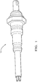
- Fig. 1 illustrates a non-limiting example of an application of electrical connector assembly used in an electrical assembly, in this example an automotive internal combustion exhaust sensor 10.
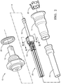
- the internal combustion exhaust sensor includes a front and rear housing 12, 14, an electrical connector assembly 16 configured to interconnect a circuit board substrate 18 containing the internal combustion exhaust sensor circuitry to a number of wire cables 20, a clip 22 configured to secure the electrical connector assembly 16 within the rear housing 14, a protective sleeve 24 to protect the wire cables 20, and a gasket 26 for mounting the front housing 12.
- the details of the electrical connector assembly 16, hereinafter referred to as the connector 16 are shown in Figs. 3 and 4 .
- the connector 16 is made up of an insulative connector body 28 and at least one electrically conductive terminal 30 that, when fully assembled, is at least partially disposed within a cavity 32 defined by the connector body 28.
- the cavity 32 is defined along a longitudinal axis X and extends from an opening 34 in a front surface 36 of the connector body 28 through to another opening in a rear surface (not shown due to perspective) of the connector body 28.
- the connector body 28 has four cavities 32 with a generally square cross section. Other embodiments with cavities having more or fewer cavities with generally rectangular, triangular, or round cross sections may also be envisioned.
- the connector body 28 is formed of a dielectric material, such as a polymeric or ceramic material.
- the choice of material will be primarily dependent on the intended application of the connector 16.
- the connector body 28 may be formed by molding the material into the desired shape. The design and fabrication of connector bodies of this type are well known to those skilled in the art.
- the terminal 30 is attached to an end of the wire cable 20, hereinafter the cable 20, and is configured to electrically interconnect to a mating terminal 38 of a mating electrical connector assembly 40.
- the terminal 30 is made up of an attachment portion 42, a connection portion 44, and a body portion 46.
- the attachment portion 42 is configured to attach the terminal 30 to the cable 20.
- the attachment portion 42 comprises a pair of crimping wings 48 that are folded and crimped to the cable 20.
- Other embodiments of the terminal 30 may be envisioned, for example in which the attachment portion 42 comprises a tubular section that is crimped or soldered to the cable 20 or a planar section to which the cable 20 is sonically welded.
- Other attachment means known to those skilled in the art may also be used for the attachment portion 42.
- connection portion 44 of the illustrated embodiment is a flexible member defining a generally triangular shape.
- the apex of the connection portion 44 defines a flexible contact tab 50 configured to contact the mating terminal 38 and flex the connection portion 44 to apply a normal force to the mating terminal 38 in order to provide a reliable electrical connection there between.
- Other embodiments of the terminal may be envisioned in which the connection portion is a male blade, a female socket, or another type of connection portion known to those skilled in the art.
- the body portion 46 of the terminal 30 is located intermediate the attachment portion 42 and the connection portion 44 and interconnects the two portions and has a generally square cross section.
- the body portion 46 defines a rigid stop tab 52 that extends laterally from one end of the body portion 46.
- the lateral direction Y is substantially orthogonal to the longitudinal direction X, i.e. ⁇ 10° of absolutely orthogonal.
- rigid means that the stop tab 52 is not deformed when subjected to forces typically experienced in the normal application of the terminal 30 and is plastically deformed when subjected to forces greater than those typically experienced in the normal application of the terminal 30.
- the body portion 46 also defines a flexible lock tab 54 on the other end of the body portion 46 that has a fixed end 56 attached to the body portion 46 and a free end 58 extending laterally outwardly, or away, from the body portion 46.
- the body portion 46 further defines a flexible bias tab 60 located intermediate the stop tab 52 and the lock tab 54.
- “flexible” means that the lock tab 54 and/or the bias tab 60 is elastically deformed when subjected to forces typically experienced in this application of the terminal 30.
- the bias tab 60 also has a fixed end 62 attached to the body portion 46 and a free end 64 extending laterally outwardly, or away, from the body portion 46.
- the terminal 30 may be formed from a tin plated copper sheet or stainless steel and the attachment portion 42, connection portion 44, body portion 46, stop tab 52, lock tab 54, and bias tab 60 may all be formed by a stamping and folding process. Other manufacturing process known to those skilled in the art may also be used to form the terminal 30.
- Figs 5 and 7 illustrate a non-limiting process of inserting the terminal 30 within the connector body 28.
- the attachment portion 42 of the terminal 30 is inserted into the opening 34 in the front surface 36 of the connector body 28.
- the free end 58 of the lock tab 54 engages a first inner cavity wall 66 and flexes inwardly toward the body portion 46 as seen with the upper terminal 30A.
- inwardly means that the free end 58 moves in a substantially lateral direction toward the longitudinal axis of the terminal 30.
- the terminal 30 is inserted into the cavity 32 until the stop tab 52 engages the front surface 36 of the connector body 28 inhibiting further longitudinal movement of the terminal 30 in the insertion direction 68.
- the lock tab 54 is located on the body portion 46 so that when the stop tab 52 engages the front surface 36, the free end 58 of the lock tab 54 is out of the cavity 32 and no longer engaging the first inner cavity wall 66 as seen with the lower terminal 30B.
- the free end 58 of the lock tab 54 then springs outwardly and engages the rear surface 70 of the connector body 28 inhibiting further longitudinal movement of the terminal 30 in the direction opposite 72 of the insertion direction 68, thereby inhibiting longitudinal movement of the terminal 30 within the cavity 32.
- "outwardly” means that the free end 58 moves in a substantially lateral direction away from the longitudinal axis of the terminal 30.
- the free end 64 of the bias tab 60 engages a second inner cavity wall 74 and urges the terminal 30 into contact with a third inner cavity wall 76 that is opposite the second inner cavity wall 74, thereby inhibiting lateral movement of the terminal 30 within the cavity 32 as seen.
- the first inner cavity wall 66 and the second inner cavity wall 74 may be different inner cavity walls or they may be the same inner cavity wall.
- the bias tab 60 does not engage any locking feature that protrudes from an inner wall within the cavity 32 nor does any other feature of the terminal 30 engage a locking feature within the cavity 32.
- the width of the bias tab 60 width is over 50% of the width of the second inner cavity wall 74. Without subscribing to any particular theory of operation, this width of the bias tab 60 inhibits rotational movement of the terminal 30 within the cavity 32.
- Other embodiments of the terminal may be envisioned having a pair of bias tabs located on the edges of the terminal that would cooperate to inhibit rotational movement of the terminal within the cavity.
- the terminals 30 are arranged in the cavities 32 of the connector body 28 such that the bias tab 60 of each one of the terminals 30 engages a distal inner cavity wall 78 of each cavity 32 and urges each of the terminals 30 toward a mesial inner cavity wall 80 of each cavity 32.
- distal inner wall refers to the inner wall of the cavity 32 that is farthest from the central longitudinal axis X of the connector body 28 and "mesial inner wall” refers to the inner wall of the cavity 32 that is closest to the central longitudinal axis X of the connector body 28. This provides the benefit of minimizing the lateral distance between the contact tabs 50 of each of the terminals 30 which further minimizes the distance between the corresponding mating terminals 38. This allows a smaller mating electrical connector assembly 40 to be used with this connector 16.
- the circuit board substrate 18 is formed of a ceramic material to accommodate the thermal environment to which the internal combustion exhaust sensor is subjected.
- Alternative electrical assemblies may use circuit board substrates formed of epoxy or polyimide resins.
- the resin may be reinforced with a woven glass cloth or other matrix such as chopped fibers.
- Substrates formed of such materials are typically ceramic or FR-4 or G-10 type circuit boards.
- the substrate may alternatively be constructed of rigid polymer materials. This listing of acceptable substrate materials is not exhaustive and other materials may also be used successfully.
- the materials and manufacturing techniques used to form circuit board substrates are well known to those skilled in the art.
- the circuit board substrate 18 defines a mating electrical connector assembly 40 with mating terminals 38 formed of conductive pads deposited near the edge of the circuit board substrate 18 that are configured to align with the contact tabs 50 of the connector 16 when the circuit board substrate 18 in fully inserted into the connector body 28 of the connector 16 as shown in Figs 6 and 8 .
- the terminal may include a second flexible bias tab (not shown).
- the bias tab and the second bias tab are configured to engage two adjacent inner walls of the cavity and urge the body of the terminal into contact with two other inner walls of the cavity opposite the two adjacent inner walls, thereby further inhibiting lateral movement of the terminal within the cavity.
- an electrical connector assembly 16 is provided.
- the bias tabs 60 defined by the terminals 30 urge the body portions 46 of the terminals 30 into contact with the inner walls of the cavities 32, thereby limiting lateral movement of the terminal 30 within the cavity 32 and decreasing the lateral positional tolerance required for the connector 16. This allows more precise lateral positioning of the terminals 30 which can successfully be used with smaller mating connector assemblies, such as the conductive pads on the edge of the circuit board substrate 18.
- the width of the bias tab 60 also is configured to limit rotational movement of the terminal 30 within the cavity 32.
- the inner walls of the cavities 32 do not define any lock features, thus simplifying the design and fabrication of the connector body 28 and reducing manufacturing cost.
- connector 16 illustrated herein is applied to interconnect a ceramic circuit board substrate 18 in an automotive internal combustion exhaust sensor 10, many other embodiments of the invention may be envisioned for many other applications of the connector.
Landscapes
- Connector Housings Or Holding Contact Members (AREA)
- Coupling Device And Connection With Printed Circuit (AREA)
- Engineering & Computer Science (AREA)
- Microelectronics & Electronic Packaging (AREA)
- Details Of Connecting Devices For Male And Female Coupling (AREA)
Abstract
An electrical connector assembly (16) having a connector body (28) and a conductive terminal (30) disposed within a cavity (32) in the connector body (28). The terminal (30) is held within the cavity (32) by a rigid stop tab (52) and a flexible lock tab (54) that engage the ends of the connector body (28). A flexible bias tab (60) having a fixed end (56) attached to the body of the terminal (30) and a free end (58) extending outward laterally from the body of the terminal (30) is configured to engage an inner wall of the cavity (32) and urge the body of the terminal (30) into contact with an opposite inner wall of the cavity (32), thereby inhibiting lateral movement of the terminal (30) within the cavity (32). The bias tab (60) may further limit rotational movement of the terminal (30) within the cavity (32). The bias tab (60) and/or any other feature of the terminal (30) do not engage a locking feature located within the cavity (32).
Description
- The invention relates to electrical connector assemblies, particularly to electrical connector assemblies providing tight lateral positional tolerances of terminals within cavities of connector housings.
- Conventional sheet metal terminals used with many different electrical connector designs have flexible lock tabs whose function is to retain and/or position the terminal in a cavity of a connector housing that is formed of a dielectric material, such as ceramic or polymer. The terminal is inserted into the cavity by pushing or pulling the terminal into the cavity, during which a free end of the lock tab contacts an inner wall of the cavity and is flexed inwardly, then the free end of the lock tab snaps (suddenly unflexes) into a pocket within the cavity or over a surface on the connector housing outside the cavity. The engagement of the lock tab with the pocket or surface inhibits the terminal from moving in the direction of insertion so that it cannot back out the way it came in. When incorporated with stop features elsewhere in the electrical connector design, the terminal is also inhibited from moving in the insertion direction; and thus becomes longitudinally locked into the connector housing cavity unless the lock tang is purposely depressed (with a screwdriver, for example) to allow removal of the terminal from the housing. While this design locates the terminal longitudinally within the connector housing, the difference in the cross sectional dimensions of the connector housing cavity and the body of the terminal needed to allow insertion of the terminal into the cavity can allow excessive or undesirable lateral positional tolerance of the terminal in the connector body.
- The size of electrical connectors continue decrease due to issues of cost, weight, and packaging of the connector. The smaller size of the connector would naturally require tighter manufacturing tolerances to assure proper fit relationship between a terminal and its mating connector cavity. However, to control manufacturing cost, the components in such miniaturized electrical connector designs preferably continue using the conventional fabrication processes and tolerances, such as injection molding or compaction pressing of the connector housing, and stamping and forming the terminal from sheet metal. Therefore, what is desired is a connection system that mimics the effects of tighter manufacturing tolerances while using existing manufacturing processes.
- The subject matter discussed in the background section should not be assumed to be prior art merely as a result of its mention in the background section. Similarly, a problem mentioned in the background section or associated with the subject matter of the background section should not be assumed to have been previously recognized in the prior art. The subject matter in the background section merely represents different approaches, which in and of themselves may also be inventions.
- In accordance with a first embodiment of the invention, an electrical connector assembly is provided. The electrical connector assembly includes a dielectric connector body defining a cavity extending longitudinally therethrough from a connector body first end to an opposed connector body second end and a conductive terminal at least partially disposed within the cavity and longitudinally oriented within the cavity. The terminal defines a rigid stop tab that extends laterally from a body of the terminal. The stop tab is configured to engage the first end of the connector body, thereby inhibiting longitudinal movement of the terminal within the cavity in a first longitudinal direction. The terminal also defines a flexible lock tab having a fixed end that is attached to the body of the terminal and a free end that extends outward laterally from the body of the terminal. The lock tab is configured to flex inwardly when contacting a first inner cavity wall of the cavity and configured to flex outwardly when the stop tab engages the first end of the connector body, thereby engaging the second end of the connector body and inhibiting longitudinal movement of the terminal within the cavity in a second longitudinal direction that is opposite the first longitudinal direction. The terminal further defines a flexible bias tab having a fixed end attached to the body of the terminal and a free end extending outward laterally from the body of the terminal. The bias tab is configured to engage a second inner wall of the cavity and urge the body of the terminal into contact with a third inner wall of the cavity that is opposite the second inner wall, thereby inhibiting lateral movement of the terminal within the cavity.
- In accordance with a second embodiment of the invention, the bias tab does not engage a locking feature within the cavity.
- In accordance with a third embodiment of the invention, the terminal does not engage a locking feature within the cavity.
- In accordance with a fourth embodiment of the invention, a bias tab width is at least 50% of a second inner wall width, thereby inhibiting rotational movement of the terminal within the cavity.
- In accordance with a fifth embodiment of the invention, the terminal includes a second flexible bias tab having a fixed end attached to the body of the terminal and a free end extending outward laterally from the body of the terminal. The bias tab and the second bias tab are configured to engage two adjacent inner walls of the cavity and urge the body of the terminal into contact with two other inner walls of the cavity opposite the two adjacent inner walls, thereby further inhibiting lateral movement of the terminal within the cavity.
- In accordance with a sixth embodiment of the invention, the terminal defines a flexible contact tab configured to engage a mating contact feature of a mating electrical connector assembly.
- In accordance with a seventh embodiment of the invention, the connector body defines a plurality of cavities extending longitudinally therethrough from the first end to the opposed second end. The electrical connector assembly comprises a plurality of terminals as described above. One terminal of the plurality of terminals is disposed within each cavity of the plurality of cavities. The bias tab of each terminal in the plurality of terminals engages a distal inner wall of each cavity in the plurality of cavities and urges each terminal in the plurality of terminals toward a mesial inner wall of each cavity in the plurality of cavities.
- In accordance with an eighth embodiment of the invention, an electrical assembly is provided. The electrical assembly includes a circuit board substrate having a mating electrical connector assembly defining a plurality of mating contact features and an electrical connector assembly as described above. The contact tabs of the plurality of terminals of the electrical connector assembly engage the plurality of mating contact features of the circuit board substrate, thus establishing an electrical connection between the circuit board substrate and the electrical connector assembly. The circuit board substrate may include an internal combustion exhaust sensor.
- The present invention will now be described, by way of example with reference to the accompanying drawings, in which:
-
Fig. 1 is a perspective view of an automotive internal combustion exhaust sensor according to one embodiment; -
Fig. 2 is an exploded perspective view of the automotive internal combustion exhaust sensor ofFig. 1 including an electrical connector assembly according to one embodiment; -
Fig 3 . is an exploded perspective view of the electrical connector assembly shown inFig. 2 according of one embodiment. -
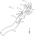
Fig. 4 is a perspective view of a terminal of the electrical connector assembly ofFig. 3 according to one embodiment; -
Fig. 5 is a cross sectional view of the electrical connector assembly ofFig. 3 along the plane A-A showing one terminal partially inserted into the connector housing and another terminal fully inserted according to one embodiment; -
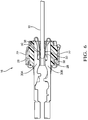
Fig. 6 is a cross sectional view of the electrical connector assembly ofFig. 3 along the plane A-A showing two terminals fully inserted into the connector housing and a circuit board substrate engaging the terminals according to one embodiment; -
Fig. 7 is a cross sectional view of the electrical connector assembly ofFig. 3 along the plane B-B showing one terminal partially inserted into the connector housing and another terminal fully inserted according to one embodiment; and -
Fig. 8 is a cross sectional view of the electrical connector assembly ofFig. 3 along the plane B-B showing two terminals fully inserted into the connector housing and a circuit board substrate engaging the terminals according to one embodiment; and -
Fig. 9 is an end view of the electrical connector assembly ofFig. 3 according to one embodiment. - Presented herein is an electrical connector assembly that provides reduced lateral positional tolerance over similar prior art connector designs. Besides the lock tab and the stop features of the terminal described in the background of the invention, the terminal includes a bias tab that protrudes from the connector body and contacts an inner wall of the connector housing cavity, forcing the connector body against the opposite inner wall of the cavity, thus inhibiting movement of the terminal within the cavity and limiting the lateral positional tolerance of the terminal in the connector housing in at least one of the lateral directions. If the width of the bias tab is sufficiently wide in relation to the width of the cavity inner wall, the bias tab may also inhibit rotational movement of the terminal within the cavity. This electrical connector may be produced using the same manufacturing methods (e.g. stamping, forming, molding) as prior art electrical connector assemblies providing an electrical connector assembly with tighter terminal location tolerances and comparable manufacturing costs compared to similar prior art electrical connector assemblies.
-
Fig. 1 illustrates a non-limiting example of an application of electrical connector assembly used in an electrical assembly, in this example an automotive internalcombustion exhaust sensor 10. As shown inFig. 2 , the internal combustion exhaust sensor includes a front andrear housing electrical connector assembly 16 configured to interconnect acircuit board substrate 18 containing the internal combustion exhaust sensor circuitry to a number ofwire cables 20, aclip 22 configured to secure theelectrical connector assembly 16 within therear housing 14, aprotective sleeve 24 to protect thewire cables 20, and agasket 26 for mounting thefront housing 12. - The details of the
electrical connector assembly 16, hereinafter referred to as theconnector 16 are shown inFigs. 3 and4 . Theconnector 16 is made up of aninsulative connector body 28 and at least one electricallyconductive terminal 30 that, when fully assembled, is at least partially disposed within acavity 32 defined by theconnector body 28. Thecavity 32 is defined along a longitudinal axis X and extends from anopening 34 in afront surface 36 of theconnector body 28 through to another opening in a rear surface (not shown due to perspective) of theconnector body 28. According to the illustrated embodiment, theconnector body 28 has fourcavities 32 with a generally square cross section. Other embodiments with cavities having more or fewer cavities with generally rectangular, triangular, or round cross sections may also be envisioned. - The
connector body 28 is formed of a dielectric material, such as a polymeric or ceramic material. The choice of material will be primarily dependent on the intended application of theconnector 16. Theconnector body 28 may be formed by molding the material into the desired shape. The design and fabrication of connector bodies of this type are well known to those skilled in the art. - As illustrated in
Fig. 4 , the terminal 30 is attached to an end of thewire cable 20, hereinafter thecable 20, and is configured to electrically interconnect to amating terminal 38 of a matingelectrical connector assembly 40. The terminal 30 is made up of anattachment portion 42, aconnection portion 44, and abody portion 46. - The
attachment portion 42 is configured to attach the terminal 30 to thecable 20. In the illustrated embodiment, theattachment portion 42 comprises a pair of crimpingwings 48 that are folded and crimped to thecable 20. Other embodiments of the terminal 30 may be envisioned, for example in which theattachment portion 42 comprises a tubular section that is crimped or soldered to thecable 20 or a planar section to which thecable 20 is sonically welded. Other attachment means known to those skilled in the art may also be used for theattachment portion 42. - The
connection portion 44 of the illustrated embodiment is a flexible member defining a generally triangular shape. The apex of theconnection portion 44 defines aflexible contact tab 50 configured to contact themating terminal 38 and flex theconnection portion 44 to apply a normal force to themating terminal 38 in order to provide a reliable electrical connection there between. Other embodiments of the terminal may be envisioned in which the connection portion is a male blade, a female socket, or another type of connection portion known to those skilled in the art. - The
body portion 46 of the terminal 30 is located intermediate theattachment portion 42 and theconnection portion 44 and interconnects the two portions and has a generally square cross section. Thebody portion 46 defines arigid stop tab 52 that extends laterally from one end of thebody portion 46. As used herein, the lateral direction Y is substantially orthogonal to the longitudinal direction X, i.e. ± 10° of absolutely orthogonal. Further, as used herein "rigid" means that thestop tab 52 is not deformed when subjected to forces typically experienced in the normal application of the terminal 30 and is plastically deformed when subjected to forces greater than those typically experienced in the normal application of the terminal 30. Thebody portion 46 also defines aflexible lock tab 54 on the other end of thebody portion 46 that has a fixedend 56 attached to thebody portion 46 and afree end 58 extending laterally outwardly, or away, from thebody portion 46. Thebody portion 46 further defines aflexible bias tab 60 located intermediate thestop tab 52 and thelock tab 54. As used herein "flexible" means that thelock tab 54 and/or thebias tab 60 is elastically deformed when subjected to forces typically experienced in this application of the terminal 30. Thebias tab 60 also has a fixedend 62 attached to thebody portion 46 and afree end 64 extending laterally outwardly, or away, from thebody portion 46. - The terminal 30 may be formed from a tin plated copper sheet or stainless steel and the
attachment portion 42,connection portion 44,body portion 46,stop tab 52,lock tab 54, andbias tab 60 may all be formed by a stamping and folding process. Other manufacturing process known to those skilled in the art may also be used to form the terminal 30. -
Figs 5 and7 illustrate a non-limiting process of inserting the terminal 30 within theconnector body 28. As shown inFig,. 5 theattachment portion 42 of the terminal 30 is inserted into theopening 34 in thefront surface 36 of theconnector body 28. As the terminal 30 is pushed through thecavity 32, thefree end 58 of thelock tab 54 engages a firstinner cavity wall 66 and flexes inwardly toward thebody portion 46 as seen with theupper terminal 30A. As used herein, "inwardly" means that thefree end 58 moves in a substantially lateral direction toward the longitudinal axis of the terminal 30. - The terminal 30 is inserted into the
cavity 32 until thestop tab 52 engages thefront surface 36 of theconnector body 28 inhibiting further longitudinal movement of the terminal 30 in theinsertion direction 68. Thelock tab 54 is located on thebody portion 46 so that when thestop tab 52 engages thefront surface 36, thefree end 58 of thelock tab 54 is out of thecavity 32 and no longer engaging the firstinner cavity wall 66 as seen with thelower terminal 30B. Thefree end 58 of thelock tab 54 then springs outwardly and engages therear surface 70 of theconnector body 28 inhibiting further longitudinal movement of the terminal 30 in the direction opposite 72 of theinsertion direction 68, thereby inhibiting longitudinal movement of the terminal 30 within thecavity 32. As used herein, "outwardly" means that thefree end 58 moves in a substantially lateral direction away from the longitudinal axis of the terminal 30. - As shown in
Fig. 7 , as theupper terminal 30C is inserted into thecavity 32, thefree end 64 of thebias tab 60 engages a secondinner cavity wall 74 and urges the terminal 30 into contact with a thirdinner cavity wall 76 that is opposite the secondinner cavity wall 74, thereby inhibiting lateral movement of the terminal 30 within thecavity 32 as seen. The firstinner cavity wall 66 and the secondinner cavity wall 74 may be different inner cavity walls or they may be the same inner cavity wall. - As illustrated in
Figs. 5 - 8 , thebias tab 60 does not engage any locking feature that protrudes from an inner wall within thecavity 32 nor does any other feature of the terminal 30 engage a locking feature within thecavity 32. - According to the illustrated embodiment, the width of the
bias tab 60 width is over 50% of the width of the secondinner cavity wall 74. Without subscribing to any particular theory of operation, this width of thebias tab 60 inhibits rotational movement of the terminal 30 within thecavity 32. Other embodiments of the terminal may be envisioned having a pair of bias tabs located on the edges of the terminal that would cooperate to inhibit rotational movement of the terminal within the cavity. - As illustrated in
Fig. 9 , theterminals 30 are arranged in thecavities 32 of theconnector body 28 such that thebias tab 60 of each one of theterminals 30 engages a distalinner cavity wall 78 of eachcavity 32 and urges each of theterminals 30 toward a mesialinner cavity wall 80 of eachcavity 32. As used herein, "distal inner wall" refers to the inner wall of thecavity 32 that is farthest from the central longitudinal axis X of theconnector body 28 and "mesial inner wall" refers to the inner wall of thecavity 32 that is closest to the central longitudinal axis X of theconnector body 28. This provides the benefit of minimizing the lateral distance between thecontact tabs 50 of each of theterminals 30 which further minimizes the distance between thecorresponding mating terminals 38. This allows a smaller matingelectrical connector assembly 40 to be used with thisconnector 16. - The
circuit board substrate 18 is formed of a ceramic material to accommodate the thermal environment to which the internal combustion exhaust sensor is subjected. Alternative electrical assemblies may use circuit board substrates formed of epoxy or polyimide resins. The resin may be reinforced with a woven glass cloth or other matrix such as chopped fibers. Substrates formed of such materials are typically ceramic or FR-4 or G-10 type circuit boards. The substrate may alternatively be constructed of rigid polymer materials. This listing of acceptable substrate materials is not exhaustive and other materials may also be used successfully. The materials and manufacturing techniques used to form circuit board substrates are well known to those skilled in the art. Thecircuit board substrate 18 defines a matingelectrical connector assembly 40 withmating terminals 38 formed of conductive pads deposited near the edge of thecircuit board substrate 18 that are configured to align with thecontact tabs 50 of theconnector 16 when thecircuit board substrate 18 in fully inserted into theconnector body 28 of theconnector 16 as shown inFigs 6 and8 . - In alternative embodiments of the connector, the terminal may include a second flexible bias tab (not shown). The bias tab and the second bias tab are configured to engage two adjacent inner walls of the cavity and urge the body of the terminal into contact with two other inner walls of the cavity opposite the two adjacent inner walls, thereby further inhibiting lateral movement of the terminal within the cavity.
- Accordingly an
electrical connector assembly 16 is provided. Thebias tabs 60 defined by theterminals 30 urge thebody portions 46 of theterminals 30 into contact with the inner walls of thecavities 32, thereby limiting lateral movement of the terminal 30 within thecavity 32 and decreasing the lateral positional tolerance required for theconnector 16. This allows more precise lateral positioning of theterminals 30 which can successfully be used with smaller mating connector assemblies, such as the conductive pads on the edge of thecircuit board substrate 18. The width of thebias tab 60 also is configured to limit rotational movement of the terminal 30 within thecavity 32. The inner walls of thecavities 32 do not define any lock features, thus simplifying the design and fabrication of theconnector body 28 and reducing manufacturing cost. - While the
connector 16 illustrated herein is applied to interconnect a ceramiccircuit board substrate 18 in an automotive internalcombustion exhaust sensor 10, many other embodiments of the invention may be envisioned for many other applications of the connector. - While this invention has been described in terms of the preferred embodiments thereof, it is not intended to be so limited, but rather only to the extent set forth in the claims that follow. Moreover, the use of the terms first, second, etc. does not denote any order of importance, but rather the terms first, second, etc. are used to distinguish one element from another. Furthermore, the use of the terms a, an, etc. do not denote a limitation of quantity, but rather denote the presence of at least one of the referenced items.
Claims (8)
- An electrical connector assembly (16), comprising:a connector body (28) defining a cavity (32) extending longitudinally therethrough from a connector body (28) first end to an opposed connector body (28) second end; anda terminal (30) at least partially disposed within the cavity (32) and longitudinally oriented within the cavity (32), said terminal (30) comprising:a rigid stop tab (52) extending laterally from a terminal body (46) and configured to engage the first end,a flexible lock tab (54) having a fixed end (56) attached to the terminal body (46) and a free end (58) extending outward laterally from the terminal body (46) and configured to flex inwardly when contacting a first cavity wall (66) and configured to flex outwardly when the stop tab (52) engages the first end, anda flexible bias tab (60) having a fixed end (62) attached to the body of the terminal (30) and a free end (64) extending outward laterally from the terminal body (46) and configured to engage a second cavity wall (74) and urge the terminal body (46) into contact with a third cavity wall (76) opposite the second cavity wall (74).
- The electrical connector assembly (16) according to claim 1, wherein the bias tab (60) does not engage a locking feature within the cavity (32).
- The electrical connector assembly (16) according to claim 1 or 2, wherein the terminal (30) does not engage a locking feature within the cavity (32).
- The electrical connector assembly (16) according to any one of the preceding claims, wherein a bias tab (60) width is at least 50% of a second cavity wall (74) width, thereby inhibiting rotational movement of the terminal (30) within the cavity (32).
- The electrical connector assembly (16) according to any one of the preceding claims, wherein the terminal (30) defines a flexible contact tab (50) configured to engage a mating contact feature of a mating electrical connector assembly (40).
- The electrical connector assembly (16) according to according to any one of the preceding claims, wherein the connector body (28) defines a plurality of cavities (32) extending longitudinally therethrough from the first end to the second end, wherein the electrical connector assembly (16) comprises a plurality of terminals (30) according to claim 5, wherein one terminal (30) of the plurality of terminals (30) is disposed within each cavity (32) of the plurality of cavities (32), and wherein the bias tab (60) of each terminal (30) in the plurality of terminals (30) engages a distal inner wall (78) of each cavity (32) in the plurality of cavities (32) and urges each terminal (30) in the plurality of terminals (30) toward a mesial inner wall (80) of each cavity (32) in the plurality of cavities (32).
- An electrical assembly, comprising:the electrical connector assembly (16) according to any one of the preceding claims, wherein the contact tabs (50) of the plurality of terminals (30) engage the plurality of mating contact features; anda circuit board substrate (18) having a mating electrical connector assembly (40) defining a plurality of mating contact features.
- The electrical assembly according to claim 7, further comprising an internal combustion exhaust sensor.
Applications Claiming Priority (1)
| Application Number | Priority Date | Filing Date | Title |
|---|---|---|---|
| US14/723,669 US9407047B1 (en) | 2015-05-28 | 2015-05-28 | Electrical connector assembly |
Publications (1)
| Publication Number | Publication Date |
|---|---|
| EP3098908A1 true EP3098908A1 (en) | 2016-11-30 |
Family
ID=56024189
Family Applications (1)
| Application Number | Title | Priority Date | Filing Date |
|---|---|---|---|
| EP16170406.9A Withdrawn EP3098908A1 (en) | 2015-05-28 | 2016-05-19 | Electrical connector assembly |
Country Status (3)
| Country | Link |
|---|---|
| US (1) | US9407047B1 (en) |
| EP (1) | EP3098908A1 (en) |
| JP (1) | JP6811550B2 (en) |
Cited By (1)
| Publication number | Priority date | Publication date | Assignee | Title |
|---|---|---|---|---|
| DE102018111036A1 (en) * | 2018-05-08 | 2019-11-14 | Tdk Electronics Ag | sensor device |
Families Citing this family (4)
| Publication number | Priority date | Publication date | Assignee | Title |
|---|---|---|---|---|
| JP2015053226A (en) * | 2013-09-09 | 2015-03-19 | タイコエレクトロニクスジャパン合同会社 | Terminal of electric connector, and electric connector |
| JP6760177B2 (en) * | 2017-03-30 | 2020-09-23 | 株式会社オートネットワーク技術研究所 | Female terminal |
| US11499467B2 (en) * | 2019-08-12 | 2022-11-15 | Delphi Technologies Ip Limited | Exhaust sensor with high-temperature terminal |
| US11757225B2 (en) * | 2021-03-11 | 2023-09-12 | Delphi Technologies Ip Limited | Electrical terminal |
Citations (4)
| Publication number | Priority date | Publication date | Assignee | Title |
|---|---|---|---|---|
| DE102004059110A1 (en) * | 2004-12-08 | 2006-06-14 | Robert Bosch Gmbh | Gas sensor |
| US7563118B1 (en) * | 2008-06-20 | 2009-07-21 | Delphi Technologies, Inc. | High temperature connector |
| DE102009036807A1 (en) * | 2009-08-10 | 2011-03-03 | Tyco Electronics Amp Gmbh | Electrical plug connector arrangement has electrical plug with contact and mating plug, where mating plug has pressing unit |
| EP2784496A2 (en) * | 2013-03-29 | 2014-10-01 | NGK Insulators, Ltd. | Electrical contact member of a sensor and method of manufacture of said sensor |
Family Cites Families (20)
| Publication number | Priority date | Publication date | Assignee | Title |
|---|---|---|---|---|
| JPS62152375U (en) * | 1986-03-18 | 1987-09-26 | ||
| JP3534230B2 (en) * | 1998-09-07 | 2004-06-07 | 住友電装株式会社 | connector |
| US6415647B1 (en) * | 1998-10-30 | 2002-07-09 | Denso Corporation | Compact structure of gas sensor and production method thereof |
| JP4542723B2 (en) * | 2001-04-27 | 2010-09-15 | 日本特殊陶業株式会社 | Sensor |
| US6527573B2 (en) * | 2001-05-22 | 2003-03-04 | Delphi Technologies, Inc. | Slide contact electrical connector |
| JP2002367714A (en) * | 2001-06-04 | 2002-12-20 | Yazaki Corp | Wire harness and method of manufacturing wire harness |
| JP4670197B2 (en) * | 2001-08-01 | 2011-04-13 | 株式会社デンソー | Gas sensor |
| JP4126179B2 (en) * | 2002-02-01 | 2008-07-30 | 住友電装株式会社 | connector |
| US6733326B2 (en) * | 2002-05-23 | 2004-05-11 | Super Link Electronics Co., Ltd. | Flexible printed circuit connector capable of resisting against lateral pressure |
| JP2006300920A (en) * | 2005-03-23 | 2006-11-02 | Denso Corp | Gas sensor |
| JP2006344458A (en) * | 2005-06-08 | 2006-12-21 | Hirose Electric Co Ltd | Surface mount type electrical connector |
| JP4723309B2 (en) * | 2005-08-11 | 2011-07-13 | 日本特殊陶業株式会社 | Sensor |
| DE102005040952A1 (en) * | 2005-08-30 | 2007-03-08 | Kostal Kontakt Systeme Gmbh | Electrical zero force connector |
| DE102006022488B4 (en) * | 2006-05-15 | 2018-07-12 | Robert Bosch Gmbh | Contact housing for an electrical connector |
| JP2007315952A (en) * | 2006-05-26 | 2007-12-06 | Denso Corp | Gas sensor |
| US8172624B2 (en) * | 2008-12-05 | 2012-05-08 | Hubbell Incorporated | Wiring device assembly with contact stabilizing structure |
| DE102009057688A1 (en) * | 2009-12-09 | 2011-06-16 | Kostal Kontakt Systeme Gmbh | Electrical zero force connector |
| DE102012002145A1 (en) * | 2012-02-04 | 2013-08-08 | Kostal Kontakt Systeme Gmbh | Sleeve contact for a zero-force electrical connector |
| TWM472352U (en) * | 2013-08-30 | 2014-02-11 | Switchlab Inc | Improved structure of wiring terminals |
| KR20150048522A (en) * | 2013-10-28 | 2015-05-07 | 주식회사 현대케피코 | Terminal for oxygen sensor |
-
2015
- 2015-05-28 US US14/723,669 patent/US9407047B1/en active Active
-
2016
- 2016-05-19 EP EP16170406.9A patent/EP3098908A1/en not_active Withdrawn
- 2016-05-25 JP JP2016103841A patent/JP6811550B2/en active Active
Patent Citations (4)
| Publication number | Priority date | Publication date | Assignee | Title |
|---|---|---|---|---|
| DE102004059110A1 (en) * | 2004-12-08 | 2006-06-14 | Robert Bosch Gmbh | Gas sensor |
| US7563118B1 (en) * | 2008-06-20 | 2009-07-21 | Delphi Technologies, Inc. | High temperature connector |
| DE102009036807A1 (en) * | 2009-08-10 | 2011-03-03 | Tyco Electronics Amp Gmbh | Electrical plug connector arrangement has electrical plug with contact and mating plug, where mating plug has pressing unit |
| EP2784496A2 (en) * | 2013-03-29 | 2014-10-01 | NGK Insulators, Ltd. | Electrical contact member of a sensor and method of manufacture of said sensor |
Cited By (1)
| Publication number | Priority date | Publication date | Assignee | Title |
|---|---|---|---|---|
| DE102018111036A1 (en) * | 2018-05-08 | 2019-11-14 | Tdk Electronics Ag | sensor device |
Also Published As
| Publication number | Publication date |
|---|---|
| US9407047B1 (en) | 2016-08-02 |
| JP6811550B2 (en) | 2021-01-13 |
| JP2016225289A (en) | 2016-12-28 |
Similar Documents
| Publication | Publication Date | Title |
|---|---|---|
| US9153889B2 (en) | Electrical connector system connectable in a straight or right angle configuration | |
| US7887350B2 (en) | Floating connector with a fixture to limit vertical movement of the connector | |
| JP2887579B2 (en) | Locking electrical connector and method of manufacturing the same | |
| CN102687346B (en) | Electrical terminal | |
| US7374432B2 (en) | Connector | |
| KR101364231B1 (en) | Connector | |
| EP2819248B1 (en) | Electrical connector with integrated moveable terminal stabilizer | |
| US9407047B1 (en) | Electrical connector assembly | |
| EP2893596B1 (en) | Electrical connector and electrical connector assembly | |
| US10530089B2 (en) | Electrical contact device, electrical contact unit as well as electrical connector | |
| JP2016062836A (en) | Connection structure of connector terminal | |
| EP1604429A1 (en) | Two-piece right angle contact edge card connector | |
| EP4228100B1 (en) | Connector assembly with an unseated terminal detection feature | |
| CN212323275U (en) | Floating connector | |
| WO2014047547A1 (en) | Floating low profile modular electrical connector system | |
| JP2007149504A (en) | Female terminals and connectors | |
| JP2014191882A (en) | Electric connector | |
| EP2162958B1 (en) | Low profile shorting bar for electrical connector | |
| WO2011077264A2 (en) | Floating connector and system | |
| US9437946B2 (en) | Printed circuit board assembly having improved terminals | |
| US7540770B2 (en) | Electrical connector | |
| CN108736212B (en) | Contact terminal assembled from at least two components | |
| US12003054B2 (en) | Terminal system of a connector system | |
| JP2012069469A (en) | connector | |
| EP4657672A1 (en) | Interlocking connector design for electrical connectors and method of assembling thereof |
Legal Events
| Date | Code | Title | Description |
|---|---|---|---|
| PUAI | Public reference made under article 153(3) epc to a published international application that has entered the european phase |
Free format text: ORIGINAL CODE: 0009012 |
|
| AK | Designated contracting states |
Kind code of ref document: A1 Designated state(s): AL AT BE BG CH CY CZ DE DK EE ES FI FR GB GR HR HU IE IS IT LI LT LU LV MC MK MT NL NO PL PT RO RS SE SI SK SM TR |
|
| AX | Request for extension of the european patent |
Extension state: BA ME |
|
| STAA | Information on the status of an ep patent application or granted ep patent |
Free format text: STATUS: THE APPLICATION IS DEEMED TO BE WITHDRAWN |
|
| 18D | Application deemed to be withdrawn |
Effective date: 20170531 |