EP3098631B1 - Small bending radius single-mode optical fiber with compatibility - Google Patents
Small bending radius single-mode optical fiber with compatibility Download PDFInfo
- Publication number
- EP3098631B1 EP3098631B1 EP14879549.5A EP14879549A EP3098631B1 EP 3098631 B1 EP3098631 B1 EP 3098631B1 EP 14879549 A EP14879549 A EP 14879549A EP 3098631 B1 EP3098631 B1 EP 3098631B1
- Authority
- EP
- European Patent Office
- Prior art keywords
- layer
- refraction
- optical fiber
- transition
- difference
- Prior art date
- Legal status (The legal status is an assumption and is not a legal conclusion. Google has not performed a legal analysis and makes no representation as to the accuracy of the status listed.)
- Active
Links
Images

Classifications
-
- G—PHYSICS
- G02—OPTICS
- G02B—OPTICAL ELEMENTS, SYSTEMS OR APPARATUS
- G02B6/00—Light guides; Structural details of arrangements comprising light guides and other optical elements, e.g. couplings
- G02B6/02—Optical fibres with cladding with or without a coating
- G02B6/036—Optical fibres with cladding with or without a coating core or cladding comprising multiple layers
- G02B6/03616—Optical fibres characterised both by the number of different refractive index layers around the central core segment, i.e. around the innermost high index core layer, and their relative refractive index difference
- G02B6/03638—Optical fibres characterised both by the number of different refractive index layers around the central core segment, i.e. around the innermost high index core layer, and their relative refractive index difference having 3 layers only
- G02B6/0365—Optical fibres characterised both by the number of different refractive index layers around the central core segment, i.e. around the innermost high index core layer, and their relative refractive index difference having 3 layers only arranged - - +
-
- G—PHYSICS
- G02—OPTICS
- G02B—OPTICAL ELEMENTS, SYSTEMS OR APPARATUS
- G02B6/00—Light guides; Structural details of arrangements comprising light guides and other optical elements, e.g. couplings
- G02B6/02—Optical fibres with cladding with or without a coating
- G02B6/036—Optical fibres with cladding with or without a coating core or cladding comprising multiple layers
- G02B6/03605—Highest refractive index not on central axis
- G02B6/03611—Highest index adjacent to central axis region, e.g. annular core, coaxial ring, centreline depression affecting waveguiding
-
- C—CHEMISTRY; METALLURGY
- C03—GLASS; MINERAL OR SLAG WOOL
- C03B—MANUFACTURE, SHAPING, OR SUPPLEMENTARY PROCESSES
- C03B2201/00—Type of glass produced
- C03B2201/02—Pure silica glass, e.g. pure fused quartz
-
- C—CHEMISTRY; METALLURGY
- C03—GLASS; MINERAL OR SLAG WOOL
- C03B—MANUFACTURE, SHAPING, OR SUPPLEMENTARY PROCESSES
- C03B2201/00—Type of glass produced
- C03B2201/06—Doped silica-based glasses
- C03B2201/08—Doped silica-based glasses doped with boron or fluorine or other refractive index decreasing dopant
- C03B2201/12—Doped silica-based glasses doped with boron or fluorine or other refractive index decreasing dopant doped with fluorine
-
- C—CHEMISTRY; METALLURGY
- C03—GLASS; MINERAL OR SLAG WOOL
- C03B—MANUFACTURE, SHAPING, OR SUPPLEMENTARY PROCESSES
- C03B2201/00—Type of glass produced
- C03B2201/06—Doped silica-based glasses
- C03B2201/30—Doped silica-based glasses doped with metals, e.g. Ga, Sn, Sb, Pb or Bi
- C03B2201/31—Doped silica-based glasses doped with metals, e.g. Ga, Sn, Sb, Pb or Bi doped with germanium
-
- C—CHEMISTRY; METALLURGY
- C03—GLASS; MINERAL OR SLAG WOOL
- C03B—MANUFACTURE, SHAPING, OR SUPPLEMENTARY PROCESSES
- C03B2203/00—Fibre product details, e.g. structure, shape
- C03B2203/10—Internal structure or shape details
- C03B2203/22—Radial profile of refractive index, composition or softening point
-
- C—CHEMISTRY; METALLURGY
- C03—GLASS; MINERAL OR SLAG WOOL
- C03B—MANUFACTURE, SHAPING, OR SUPPLEMENTARY PROCESSES
- C03B2203/00—Fibre product details, e.g. structure, shape
- C03B2203/10—Internal structure or shape details
- C03B2203/22—Radial profile of refractive index, composition or softening point
- C03B2203/23—Double or multiple optical cladding profiles
Definitions
- the present invention relates to the field of single-mode optical fibers, and specifically to a small bending radius single-mode optical fiber with compatibility with conventional optical fibres.
- Improving the resistance-to-bending performance of optical fibers can not only be good for guaranteeing the high-quality transmission of optical signals, but also reduce the overall heating value of the communication system of the optical fibers so as to promote the overall performance of the system.
- Global leading enterprises of optical fibers have carried out in-depth studies on the requirements of the hotspot ODN technology of communication networks upon super-strong bending-resistant optical fibers.
- Domestic optical fiber and cable enterprises have currently focused on the technical studies of a 10mm bending radius required by the ITUT-G.657 or a smaller bending radius single-mode optical fiber, like G.657B2/3.
- Optical fibers for FTTH actually need two key characteristics, one is resistance to bending, a fundamental characteristic to achieve the small bending radius and low loss transmission of optical signals, the other is certain compatibility with conventional G.652 optical fibers. Nearly all the optical fibers arranged in a large number at the front end of the current backbone network and metropolitan area network or even access network are G.652 optical fibers.
- the optical fibers chosen for the FTTH section cannot be well compatible with the G.652 optical fibers, even though they have high bending performance, a large loss can be caused when they are fused with the conventional G.652 optical fibers, and the optical signals can also be largely depleted at the connection of the two optical fibers, thus an additionally greater optical gain is needed, or else the G.652 optical fibers will still be used at the FTTH end. Therefore, although bending-resistant optical fibers have been supplied now, as they cannot be well compatibility with the conventional G.652 optical fibers, they are not massively adopted in the FTTH market.
- a small bending radius single mode optical fibre is known from US2007189699 .
- the present invention provides a small bending radius single-mode optical fiber with compatibility with conventional G.652 optical fibres, which achieves a quite strong resistance to bending, the radius of which is below 2mm, and is well compatible with conventional single-mode optical fibers.
- the ratio of the thickness of the germanium-doped core layer to the thickness of the first wrapping layer is from 0.5 to 2.0.
- the ratio of the thickness of the germanium-doped core layer to the thickness of the second wrapping layer is from 0.2 to 1.0.
- the difference of relative index of refraction of the germanium-doped core layer is from 0.2% to 0.8%.
- the difference of relative index of refraction of the first wrapping layer is from 0 to 0.1%.
- the difference of relative index of refraction of the second wrapping layer is from -1.3% to -0.3%.
- the diameter of the third wrapping layer, a quartz wrapping layer is 80 ⁇ m or 125 ⁇ m.
- the attenuation of the small bending radius single-mode optical fiber is below 0.2dB/km, and when the bending radius is below 2mm, the additional loss is below 0.35dB.
- a small bending radius single-mode optical fiber with compatibility with conventional G.652 optical fibres of the present invention comprises a core gradient layer 1, a germanium-doped core layer 2, a first transition layer 3, a first wrapping layer 4, a second transition layer 5, a second wrapping layer 6, a third transition layer 7 and a third wrapping layer 8, said layers being arranged concentrically from the inner to the outer, wherein the core gradient layer 1 is arranged inside the germanium-doped core layer 2, the first transition layer 3 is located between the core gradient layer 1 and the first wrapping layer 4, the second transition layer 5 is located between the first wrapping layer 4 and the second wrapping layer 6, and the third transition layer 7 is located between the second wrapping layer 6 and the third wrapping layer 8; the ratio of the thickness L2 of the germanium-doped core layer 2 to the thickness L4 of the first wrapping layer 4 is from 0.5 to 2.0; the ratio of the thickness L2 of the germanium-doped core layer 2 to the thickness L6 of the second wrapping layer 6 is from 0.2 to
- the index of refraction of the core gradient layer 1 is n1
- the index of refraction of the germanium-doped layer 2 is n2
- the index of refraction of the first transition layer 3 is n3
- the index of refraction of the first wrapping layer 4 is n4
- the index of refraction of the third transition layer 5 is n5
- the index of refraction of the second wrapping layer 6 is n6
- the index of refraction of the third wrapping layer 7 is n7
- the index of refraction of the third wrapping layer 8 is n8
- the index of refraction of the third wrapping layer 8, namely n8 is chosen as the index of refraction of an equivalent quartz wrapping layer, namely n.
- n the index of refraction of the quartz wrapping layer, namely the index of refraction of the third wrapping layer 8 of the present invention, n8, and n' is the index of refraction of the corresponding layer.
- n' in the equation adopts the index of refraction of the fiber core, namely n1; to calculate the difference of relative index of refraction of the germanium-doped core layer and the quartz wrapping layer, n' in the equation adopts the index of refraction of the fiber core, namely n2; to calculate the difference of relative index of refraction of the core of the first transition layer 3 and the quartz wrapping layer, n' in the equation adopts the index of refraction of the first transition layer, namely n3; to calculate the difference of relative index of refraction of the first wrapping layer 4 and the quartz wrapping layer, n' in the equation adopts the index of refraction of the first wrapping layer, namely n4; to calculate the difference of relative index of refraction of the second transition layer 5 and the quartz wrapping layer, n' in the equation adopts the index of refraction of the second transition layer, namely n5
- the difference of relative index of refraction of the core gradient layer 1 is ⁇ n1
- the difference of relative index of refraction of the germanium-doped core layer 2 is ⁇ n2
- the difference of relative index of refraction of the first transition layer 3 is ⁇ n3
- the difference of relative index of refraction of the first wrapping layer 4 is ⁇ n4
- the difference of relative index of refraction of the second transition layer 5 is ⁇ n5
- the difference of relative index of refraction of the second wrapping layer 6 is ⁇ n6
- the difference of relative index of refraction of the third transition layer 7 is ⁇ n7.
- the difference of relative index of refraction of the germanium-doped core layer 2 is between 0.2% and 0.8%; the difference of relative index of refraction of the first wrapping layer 4, a low germanium-doped wrapping layer, is between 0 and 0.1%; the difference of relative index of refraction of the second wrapping layer 6, a high fluorine-doped wrapping layer, is between -1.3% and -0.3%.
- ⁇ n1 a 1 (x 1 + x 1 2 + x 1 3 ) + b 1 , wherein x 1 is the distance from any point within the core gradient layer 1 to the axis of said layer, a 1 is gradient factor of the core gradient layer 1, ranging from 0.5% to 2%, and b 1 is gradient stability factor of the core gradient layer 1, ranging from 0 to 0.2%.
- a triplex control is applied to the mode field of the small bending radius optical fiber through the germanium-doped fiber core 2, the first wrapping layer 4, the second wrapping layer 6 and the third wrapping layer 8, and the characteristics of the mode field are optimized to adapt to G.652 through the core gradient layer 1, the first transition layer 3, the second transition layer 5 and the third transition layer 7, thus the epitaxial mode field of the optical fiber is approximate to the mode field of G.652, and the central mode field is the characteristic mode field of the small bending radius optical fiber.
Landscapes
- Physics & Mathematics (AREA)
- General Physics & Mathematics (AREA)
- Optics & Photonics (AREA)
- Manufacture, Treatment Of Glass Fibers (AREA)
- Optical Communication System (AREA)
- Glass Compositions (AREA)
- Lasers (AREA)
Description
- The present invention relates to the field of single-mode optical fibers, and specifically to a small bending radius single-mode optical fiber with compatibility with conventional optical fibres.
- At present, the construction of communication networks has mobilized the rapid development of fiber-to-the-home (FTTH) and ODN technology, which put forward a high requirement upon the resistance-to-bending performance of optical fibers. When the optical fibers are bent, some light of power leaks to make optical signals attenuated. Materials such as the coating absorb the leaked light and thus are heated. Studies have found that after running for a long time under the bending radius of 15mm, a jumper made of conventional G.652D single-mode optical fibers will be destroyed between two connection end points due to continued heating, thus leading to the continued reduction of splicing loss and non-recoverable damage. In the ODN, a great number of optical fibers are arranged in a bending manner in a small distributor. As the bending of the optical fibers leads to the leak of optical power, heating is resulted. It will severely influence the communication stability of the ODN.
- Improving the resistance-to-bending performance of optical fibers can not only be good for guaranteeing the high-quality transmission of optical signals, but also reduce the overall heating value of the communication system of the optical fibers so as to promote the overall performance of the system. Global leading enterprises of optical fibers have carried out in-depth studies on the requirements of the hotspot ODN technology of communication networks upon super-strong bending-resistant optical fibers. Domestic optical fiber and cable enterprises have currently focused on the technical studies of a 10mm bending radius required by the ITUT-G.657 or a smaller bending radius single-mode optical fiber, like G.657B2/3.
- However, to meet the floor space requirement of the construction of optical fiber networks and 3G networks, the ODN technology demands that a great number of devices are disposed in a rather small distributor. As a consequence, the space for the optical fibers for high-speed high-bandwidth communication connection between the devices is narrowed, and the bending performance of the optical fibers must be higher. Super-strong bending-resistant single-mode optical fibers, of which the bending radius is 3mm or even 2mm below, are needed in more and more applications. Besides, such super-strong bending-resistant single-mode optical fibers must be well compatible with common single-mode optical fibers; their single-point fusion loss must be controlled within an acceptable small range.
- Optical fibers for FTTH actually need two key characteristics, one is resistance to bending, a fundamental characteristic to achieve the small bending radius and low loss transmission of optical signals, the other is certain compatibility with conventional G.652 optical fibers. Nearly all the optical fibers arranged in a large number at the front end of the current backbone network and metropolitan area network or even access network are G.652 optical fibers. If the optical fibers chosen for the FTTH section cannot be well compatible with the G.652 optical fibers, even though they have high bending performance, a large loss can be caused when they are fused with the conventional G.652 optical fibers, and the optical signals can also be largely depleted at the connection of the two optical fibers, thus an additionally greater optical gain is needed, or else the G.652 optical fibers will still be used at the FTTH end. Therefore, although bending-resistant optical fibers have been supplied now, as they cannot be well compatibility with the conventional G.652 optical fibers, they are not massively adopted in the FTTH market.
- A small bending radius single mode optical fibre is known from
US2007189699 . - Aiming to overcome the defects of the prior art, the present invention provides a small bending radius single-mode optical fiber with compatibility with conventional G.652 optical fibres, which achieves a quite strong resistance to bending, the radius of which is below 2mm, and is well compatible with conventional single-mode optical fibers.
- To achieve the above-mentioned aim, the present invention adopts a technical scheme as follows: a small bending radius single-mode optical fiber with compatibility with conventional G.652 optical fibres comprises a core gradient layer and a germanium-doped core layer arranged concentrically, and a first wrapping layer, a second wrapping layer and a third wrapping layer arranged concentrically from the inner to the outer; a first transition layer is arranged between the germanium-doped core layer and the first wrapping layer, a second transition layer is arranged between the first wrapping layer and the second wrapping layer, and a third transition layer is arranged between the second wrapping layer and the third wrapping layer; the difference of relative index of refraction of the core gradient layer is Δn1, which is realized through an equation: Δn1 = a1(x1 + x1 2 + x1 3) + b1, wherein x1 is the distance from any point within the core gradient layer to the axis of said layer, a1 is gradient factor of the core gradient layer, ranging from 0.5% to 2%, and b1 is gradient stability factor of the core gradient layer, ranging from 0 to 0.2%; the difference of relative index of refraction of the first transition layer is Δn3, which is realized through an equation: Δn3 = b3(1 - a3x3 2)0.5, wherein x3 is the distance from a concentric circle around the centre of an optical fiber at any point within the
first transition layer 3 to the outer edge of the germanium-dopedcore layer 2, and a3 and b3 are transition factors, both ranging from 0.3% to 0.8%; the difference of relative index of refraction of the second transition layer is Δn5, which is realized through an equation: Δn5 = a5x5 2 + b5, wherein x5 is the distance from a concentric circle around the centre of an optical fiber at any point within thesecond transition layer 5 to the outer edge of thefirst wrapping layer 4, and as and b5 are transition factors, as ranging from -1.0% to -0.3%, and b5 ranging from 0 to 0.1%; and the difference of relative index of refraction of the third transition layer is Δn7, which is realized through an equation: Δn7 = a7x7 2 + b7, wherein x7 is the distance from a concentric circle around the centre of an optical fiber at any point within thethird transition layer 7 to the outer edge of thesecond wrapping layer 6, and a7 and b7 are transition factors, a7 ranging from 0.1% to 0.4%, and b7 ranging from -1.3% to -0.3%. - Based on the above-mentioned technical scheme, the ratio of the thickness of the germanium-doped core layer to the thickness of the first wrapping layer is from 0.5 to 2.0.
- Based on the above-mentioned technical scheme, the ratio of the thickness of the germanium-doped core layer to the thickness of the second wrapping layer is from 0.2 to 1.0.
- Based on the above-mentioned technical scheme, the difference of relative index of refraction of the germanium-doped core layer is from 0.2% to 0.8%.
- Based on the above-mentioned technical scheme, the difference of relative index of refraction of the first wrapping layer is from 0 to 0.1%.
- Based on the above-mentioned technical scheme, the difference of relative index of refraction of the second wrapping layer is from -1.3% to -0.3%.
- Based on the above-mentioned technical scheme, the diameter of the third wrapping layer, a quartz wrapping layer, is 80µm or 125µm.
- Based on the above-mentioned technical scheme, when the operating wavelength is 1550nm, the attenuation of the small bending radius single-mode optical fiber is below 0.2dB/km, and when the bending radius is below 2mm, the additional loss is below 0.35dB.
- The present invention has the following beneficial effects:
- 1. a plurality of wrapping layers, namely a first wrapping layer doped with low germanium, a second wrapping layer doped with high fluorine and a third wrapping layer composed of quartz, are arranged outside a germanium-doped core layer to form a mountain-shaped waveguide structure, thus strengthening the resistance to bending of the optical fiber through the reduction of macrobend and microbend losses; and
- 2. a transition layer is arranged between the germanium-doped core layer and the first wrapping layer, as well as between the first and the second wrapping layers and between the second and the third wrapping layers, and a core gradient layer is arranged inside the germanium-doped core layer, so that the mode and stress characteristics of the optical fiber are optimized; therefore, when the small bending radius single-mode optical fiber is fused with conventional G.652 single-mode optical fibers, the loss at the fusion point can be controlled to the minimum, and the small bending radius single-mode optical fiber is well compatible with the conventional single-mode optical fibers, thus laying the foundation for optical fibers for FTTH and ODN technology.
-
-
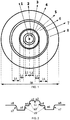
FIG. 1 is a schematic structural diagram of an end face of a small bending radius single-mode optical fiber with compatibility of the present invention; -
FIG. 2 is a schematic structural diagram of a waveguide of a small bending radius single-mode optical fiber with compatibility of the present invention; -
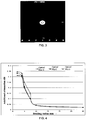
FIG. 3 is a schematic structural diagram of mode field control of a small bending radius single-mode optical fiber with compatibility; -
FIG. 4 is an additional loss for optical fiber bending when a wrapping layer inFIG. 1 is 125µm in diameter; and -
FIG. 5 is an additional loss for optical fiber bending when a wrapping layer inFIG. 1 is 80µm in diameter. - The following will further describe the present invention according to drawings.
- As shown in
FIG. 1 , a small bending radius single-mode optical fiber with compatibility with conventional G.652 optical fibres of the present invention comprises acore gradient layer 1, a germanium-dopedcore layer 2, afirst transition layer 3, afirst wrapping layer 4, asecond transition layer 5, asecond wrapping layer 6, athird transition layer 7 and athird wrapping layer 8, said layers being arranged concentrically from the inner to the outer, wherein thecore gradient layer 1 is arranged inside the germanium-dopedcore layer 2, thefirst transition layer 3 is located between thecore gradient layer 1 and thefirst wrapping layer 4, thesecond transition layer 5 is located between thefirst wrapping layer 4 and thesecond wrapping layer 6, and thethird transition layer 7 is located between thesecond wrapping layer 6 and thethird wrapping layer 8; the ratio of the thickness L2 of the germanium-dopedcore layer 2 to the thickness L4 of thefirst wrapping layer 4 is from 0.5 to 2.0; the ratio of the thickness L2 of the germanium-dopedcore layer 2 to the thickness L6 of thesecond wrapping layer 6 is from 0.2 to 1.0; the diameter D8 of thethird wrapping layer 8, a quartz wrapping layer, is 80µm or 125µm; after being coated, the small bending radius single-mode optical fiber of the present invention has the diameter of 200µm or 245µm. - As shown in
FIG. 2 , the index of refraction of thecore gradient layer 1 is n1, the index of refraction of the germanium-dopedlayer 2 is n2, the index of refraction of thefirst transition layer 3 is n3, the index of refraction of thefirst wrapping layer 4 is n4, the index of refraction of thethird transition layer 5 is n5, the index of refraction of thesecond wrapping layer 6 is n6, the index of refraction of thethird wrapping layer 7 is n7, and the index of refraction of thethird wrapping layer 8 is n8; the index of refraction of thethird wrapping layer 8, namely n8, is chosen as the index of refraction of an equivalent quartz wrapping layer, namely n. To realize these indexes of refraction, a method of difference of relative index of refraction is adopted. On the basis of the index of refraction of the quartz wrapping layer, namely n, a difference of relative index of refraction occurs between each waveguide layer and the quartz wrapping layer. Accordingly, the index of refraction of each layer included in the mountain-shaped waveguide structure of the present invention is measured and realized. An equation is adopted for the difference of relative index of refraction:
third wrapping layer 8 of the present invention, n8, and n' is the index of refraction of the corresponding layer. - As for the present invention, to calculate the difference of relative index of refraction of the
core gradient layer 1 and the quartz wrapping layer, n' in the equation adopts the index of refraction of the fiber core, namely n1; to calculate the difference of relative index of refraction of the germanium-doped core layer and the quartz wrapping layer, n' in the equation adopts the index of refraction of the fiber core, namely n2; to calculate the difference of relative index of refraction of the core of thefirst transition layer 3 and the quartz wrapping layer, n' in the equation adopts the index of refraction of the first transition layer, namely n3; to calculate the difference of relative index of refraction of thefirst wrapping layer 4 and the quartz wrapping layer, n' in the equation adopts the index of refraction of the first wrapping layer, namely n4; to calculate the difference of relative index of refraction of thesecond transition layer 5 and the quartz wrapping layer, n' in the equation adopts the index of refraction of the second transition layer, namely n5; to calculate the difference of index of refraction of thesecond wrapping layer 6 and the fluorine-doped wrapping layer, n' in the equation adopts the index of refraction of the second wrapping layer, namely n6; to calculate the difference of index of refraction of thethird transition layer 7 and the quartz wrapping layer, n' in the equation adopts the index of refraction of the second transition layer, namely n7. - Accordingly, it can be figured out by the equation (1) that the difference of relative index of refraction of the
core gradient layer 1 is Δn1, the difference of relative index of refraction of the germanium-dopedcore layer 2 is Δn2, the difference of relative index of refraction of thefirst transition layer 3 is Δn3, the difference of relative index of refraction of thefirst wrapping layer 4 is Δn4, the difference of relative index of refraction of thesecond transition layer 5 is Δn5, the difference of relative index of refraction of thesecond wrapping layer 6 is Δn6, and the difference of relative index of refraction of thethird transition layer 7 is Δn7. The difference of relative index of refraction of the germanium-dopedcore layer 2 is between 0.2% and 0.8%; the difference of relative index of refraction of thefirst wrapping layer 4, a low germanium-doped wrapping layer, is between 0 and 0.1%; the difference of relative index of refraction of thesecond wrapping layer 6, a high fluorine-doped wrapping layer, is between -1.3% and -0.3%. - The difference of relative index of refraction of the
core gradient layer 1 is Δn1, which is realized through an equation: Δn1 = a1(x1 + x1 2 + x1 3) + b1, wherein x1 is the distance from any point within thecore gradient layer 1 to the axis of said layer, a1 is gradient factor of thecore gradient layer 1, ranging from 0.5% to 2%, and b1 is gradient stability factor of thecore gradient layer 1, ranging from 0 to 0.2%. - The difference of relative index of refraction of the
first transition layer 3 is Δn3, which is realized through an equation: Δn3 = b3(1 - a3x3 2)0.5, wherein x3 is the distance from a concentric circle around the centre of an optical fiber at any point within thefirst transition layer 3 to the outer edge of the germanium-dopedcore layer 2, and a3 and b3 are transition factors, both ranging from 0.3% to 0.8%. - The difference of relative index of refraction of the
second transition layer 5 is Δn5, which is realized through an equation: Δn5 = a5x5 2 + b5, wherein x5 is the distance from a concentric circle around the centre of an optical fiber at any point within thesecond transition layer 5 to the outer edge of thefirst wrapping layer 4, and as and b5 are transition factors, as ranging from -1.0% to -0.3%, and b5 ranging from 0 to 0.1%. - The difference of relative index of refraction of the
third transition layer 7 is Δn7, which is realized through an equation: Δn7 = a7x7 2 + b7, wherein x7 is the distance from a concentric circle around the centre of an optical fiber at any point within thethird transition layer 7 to the outer edge of thesecond wrapping layer 6, and a7 and b7 are transition factors, a7 ranging from 0.1% to 0.4%, and b7 ranging from -1.3% to -0.3%. - As shown in
FIG. 3 , according to the present invention, a triplex control is applied to the mode field of the small bending radius optical fiber through the germanium-dopedfiber core 2, thefirst wrapping layer 4, thesecond wrapping layer 6 and thethird wrapping layer 8, and the characteristics of the mode field are optimized to adapt to G.652 through thecore gradient layer 1, thefirst transition layer 3, thesecond transition layer 5 and thethird transition layer 7, thus the epitaxial mode field of the optical fiber is approximate to the mode field of G.652, and the central mode field is the characteristic mode field of the small bending radius optical fiber. - The following will further describe the present invention according to embodiments.
- Embodiment 1:
- in this embodiment, a small bending radius single-mode optical fiber, the diameter D8 of a
third wrapping layer 8 is 125µm; the difference of relative index of refraction of acore gradient layer 1 is Δn1, which is realized through an equation: Δn1 = a1(x1 + x1 2 + x1 3) + b1, wherein x1 is the distance from any point within thecore gradient layer 1 to the axis of said layer, a1 is gradient factor of thecore gradient layer 1, falling within 0.5%, and b1 is gradient stability factor of thecore gradient layer 1, falling within 0; - the difference of relative index of refraction of a germanium-doped
core layer 2, namely Δn2, keeps stable, constantly 0.2%; - the difference of relative index of refraction of a
first transition layer 3 is Δn3, which is realized through an equation: Δn3 = b3(1 -a3x32)0.5, wherein x3 is the distance from a concentric circle around the centre of an optical fiber at any point within thefirst transition layer 3 to the outer edge of the germanium-dopedcore layer 2, and as and b3 are transition factors, a3 falling within 0.8%, and b3 falling within 0.3%; - the difference of relative index of refraction of a
first wrapping layer 4, namely Δn4, keeps stable, constantly 0; the ratio of the thickness L2 of the germanium-dopedcore layer 2 to the thickness L4 of thefirst wrapping layer 4 is 2.0; - the difference of relative index of refraction of a
second transition layer 5 is Δn5, which is realized through an equation: Δn5 = a5x5 2 + b5, wherein x5 is the distance from a concentric circle around the centre of an optical fiber at any point within thesecond transition layer 5 to the outer edge of thefirst wrapping layer 4, and a5 and b5 are transition factors, a5 falling within -0.65%, and b5 falling within 0.05%; - the difference of relative index of refraction of a
second wrapping layer 6, namely Δn6, keeps stable, constantly -0.8%; the ratio of the thickness L2 of the germanium-dopedcore layer 2 to the thickness L4 of thesecond wrapping layer 6 is 1.0; - the difference of relative index of refraction of a
third transition layer 7 is Δn7, which is realized through an equation: Δn7 = a7x7 2 + b7, wherein x7 is the distance from a concentric circle around the centre of an optical fiber at any point within thethird transition layer 7 to the outer edge of thesecond wrapping layer 6, and a7 and b7 are transition factors, a7 falling within 0.25%, and b7 falling within -0.8%; - according to
FIG. 4 , in this embodiment, the 1550nm attenuation of the small bending radius single-mode optical fiber is 0.191dB/km, the fusion loss between the small bending radius single-mode optical fiber and a conventional G.652 optical fiber reaches 0.08dB, and the additional loss under the bending radius of 2mm is below 0.345dB.
- in this embodiment, a small bending radius single-mode optical fiber, the diameter D8 of a
- Embodiment 2:
- this embodiment is of a structure basically the same as
embodiment 1; the diameter D8 of athird wrapping layer 8 is 125µm; the difference of relative index of refraction of acore gradient layer 1 is Δn1, which is realized through an equation: Δn1 = a1(x1 + x1 2 + x1 3) + b1, wherein x1 is the distance from any point within thecore gradient layer 1 to the axis of said layer, a1 is gradient factor of thecore gradient layer 1, falling within 1%, and b1 is gradient stability factor of thecore gradient layer 1, falling within 0.2; - the difference of relative index of refraction of a germanium-doped
core layer 2, namely Δn2, keeps stable, constantly 0.5%; - the difference of relative index of refraction of a
first transition layer 3 is Δn3, which is realized through an equation: Δn3 = b3(1 - a3x3 2)0.5, wherein x3 is the distance from a concentric circle around the centre of an optical fiber at any point within thefirst transition layer 3 to the outer edge of the germanium-dopedcore layer 2, and a3 and b3 are transition factors, a3 falling within 0.5, and b3 falling within 0.5%; - the difference of relative index of refraction of a
first wrapping layer 4, namely Δn4, keeps stable, constantly 0; the ratio of the thickness L2 of the germanium-dopedcore layer 2 to the thickness L4 of thefirst wrapping layer 4 is 1.0; - the difference of relative index of refraction of a
second transition layer 5 is Δn5, which is realized through an equation: Δn5 = a5x5 2 + b5, wherein x5 is the distance from a concentric circle around the centre of an optical fiber at any point within thesecond transition layer 5 to the outer edge of thefirst wrapping layer 4, and a5 and b5 are transition factors, a5 falling within -0.3%, and b5 falling within 0.1%; - the difference of relative index of refraction of a
second wrapping layer 6, namely Δn6, keeps stable, constantly -0.3%; the ratio of the thickness L2 of the germanium-dopedcore layer 2 to the thickness L4 of thesecond wrapping layer 6 is 0.5; - the difference of relative index of refraction of a
third transition layer 7 is Δn7, which is realized through an equation: Δn7 = a7x7 2 + b7, wherein x7 is the distance from a concentric circle around the centre of an optical fiber at any point within thethird transition layer 7 to the outer edge of thesecond wrapping layer 6, and a7 and b7 are transition factors, a7 falling within 0.1%, and b7 falling within -0.3%; - according to
FIG. 4 , in this embodiment, the 1550nm attenuation of the small bending radius single-mode optical fiber is 0.193dB/km, the fusion loss between the small bending radius single-mode optical fiber and a conventional G.652 optical fiber reaches 0.11dB, and the additional loss under the bending radius of 2mm is below 0.332dB.
- this embodiment is of a structure basically the same as
- Embodiment 3:
- this embodiment is of a structure basically the same as
embodiment 1; the diameter D8 of athird wrapping layer 8 is 125µm; the difference of relative index of refraction of acore gradient layer 1 is Δn1, which is realized through an equation: Δn1 = a1(x1 + x1 2 + x1 3) + b1, wherein x1 is the distance from any point within thecore gradient layer 1 to the axis of said layer, a1 is gradient factor of thecore gradient layer 1, falling within 2%, and b1 is gradient stability factor of thecore gradient layer 1, falling within 0.1; - the difference of relative index of refraction of a germanium-doped
core layer 2, namely Δn2, keeps stable, constantly 0.8%; - the difference of relative index of refraction of a
first transition layer 3 is Δn3, which is realized through an equation: Δn3 = b3(1 - a3x3 2)0.5, wherein x3 is the distance from a concentric circle around the centre of an optical fiber at any point within thefirst transition layer 3 to the outer edge of the germanium-dopedcore layer 2, and a3 and b3 are transition factors, a3 falling within 0.3, and b3 falling within 0.8%; - the difference of relative index of refraction of a
first wrapping layer 4, namely Δn4, keeps stable, constantly 0; the ratio of the thickness L2 of the germanium-dopedcore layer 2 to the thickness L4 of thefirst wrapping layer 4 is 0.5; - the difference of relative index of refraction of a
second transition layer 5 is Δn5, which is realized through an equation: Δn5 = a5x5 2 + b5, wherein x5 is the distance from a concentric circle around the centre of an optical fiber at any point within thesecond transition layer 5 to the outer edge of thefirst wrapping layer 4, and a5 and b5 are transition factors, a5 falling within -1.3%, and b5 falling within 0%; - the difference of relative index of refraction of a
second wrapping layer 6, namely Δn6, keeps stable, constantly -1.3%; the ratio of the thickness L2 of the germanium-dopedcore layer 2 to the thickness L4 of thesecond wrapping layer 6 is 0.2; - the difference of relative index of refraction of a
third transition layer 7 is Δn7, which is realized through an equation: Δn7 = a7x7 2 + b7, wherein x7 is the distance from a concentric circle around the centre of an optical fiber at any point within thethird transition layer 7 to the outer edge of thesecond wrapping layer 6, and a7 and b7 are transition factors, a7 falling within 0.4%, and b7 falling within -1.3%; - according to
FIG. 4 , in this embodiment, the 1550nm attenuation of the small bending radius single-mode optical fiber is 0.194dB/km, the fusion loss between the small bending radius single-mode optical fiber and a conventional G.652 optical fiber reaches 0.15dB, and the additional loss under the bending radius of 2mm is below 0.311dB.
- this embodiment is of a structure basically the same as
- Embodiment 4:
- in this embodiment, the diameter D8 of a
third wrapping layer 8 is 80µm; the difference of relative index of refraction of acore gradient layer 1 is Δn1, which is realized through an equation: Δn1 = a1(x1 + x1 2 + x1 3) + b1, wherein x1 is the distance from any point within thecore gradient layer 1 to the axis of said layer, a1 is gradient factor of thecore gradient layer 1, falling within 0.5%, and b1 is gradient stability factor of thecore gradient layer 1, falling within 0; - the difference of relative index of refraction of a germanium-doped
core layer 2, namely Δn2, keeps stable, constantly 0.2%; - the difference of relative index of refraction of a
first transition layer 3 is Δn3, which is realized through an equation: Δn3 = b3(1 - a3x3 2)0.5, wherein x3 is the distance from a concentric circle around the centre of an optical fiber at any point within thefirst transition layer 3 to the outer edge of the germanium-dopedcore layer 2, and a3 and b3 are transition factors, a3 falling within 0.8, and b3 falling within 0.3%; - the difference of relative index of refraction of a
first wrapping layer 4, namely Δn4, keeps stable, constantly 0; the ratio of the thickness L2 of the germanium-dopedcore layer 2 to the thickness L4 of thefirst wrapping layer 4 is 2.0; - the difference of relative index of refraction of a
second transition layer 5 is Δn5, which is realized through an equation: Δn5 = a5x5 2 + b5, wherein x5 is the distance from a concentric circle around the centre of an optical fiber at any point within thesecond transition layer 5 to the outer edge of thefirst wrapping layer 4, and a5 and b5 are transition factors, a5 falling within -0.75%, and b5 falling within 0.06%; - the difference of relative index of refraction of a
second wrapping layer 6, namely Δn6, keeps stable, constantly -0.9%; the ratio of the thickness L2 of the germanium-dopedcore layer 2 to the thickness L4 of thesecond wrapping layer 6 is 1.0; - the difference of relative index of refraction of a
third transition layer 7 is Δn7, which is realized through an equation: Δn7 = a7x7 2 + b7, wherein x7 is the distance from a concentric circle around the centre of an optical fiber at any point within thethird transition layer 7 to a concentric circle around the centre of an optical fiber at the outer edge of thesecond wrapping layer 6, and a7 and b7 are transition factors, a7 falling within 0.3%, and b7 falling within -0.9%; - according to
FIG. 5 , in this embodiment, the 1550nm attenuation of the small bending radius single-mode optical fiber is 0.195dB/km, the fusion loss between the small bending radius single-mode optical fiber and a conventional G.652 optical fiber reaches 0.13dB, and the additional loss under the bending radius of 2mm is below 0.332dB.
- in this embodiment, the diameter D8 of a
- Embodiment 5:
- this embodiment is of a structure basically the same as
embodiment 5; the diameter D8 of athird wrapping layer 8 is 80µm; the difference of relative index of refraction of acore gradient layer 1 is Δn1, which is realized through an equation: Δn1 = a1(x1 + x1 2 + x1 3) + b1, wherein x1 is the distance from any point within thecore gradient layer 1 to the axis of said layer, a1 is gradient factor of thecore gradient layer 1, falling within 1.3%, and b1 is gradient stability factor of thecore gradient layer 1, falling within 0.2; - the difference of relative index of refraction of a germanium-doped
core layer 2, namely Δn2, keeps stable, constantly 0.6%; - the difference of relative index of refraction of a
first transition layer 3 is Δn3, which is realized through an equation: Δn3 = b3(1 - a3x3 2)0.5, wherein x3 is the distance from a concentric circle around the centre of an optical fiber at any point within thefirst transition layer 3 to the outer edge of the germanium-dopedcore layer 2, and a3 and b3 are transition factors, a3 falling within 0.6, and b3 falling within 0.45%; - the difference of relative index of refraction of a
first wrapping layer 4, namely Δn4, keeps stable, constantly 0; the ratio of the thickness L2 of the germanium-dopedcore layer 2 to the thickness L4 of thefirst wrapping layer 4 is 0.9; - the difference of relative index of refraction of a
second transition layer 5 is Δn5, which is realized through an equation: Δn5 = a5x5 2 + b5, wherein x5 is the distance from a concentric circle around the centre of an optical fiber at any point within thesecond transition layer 5 to the outer edge of thefirst wrapping layer 4, and as and b5 are transition factors, as falling within -0.3%, and b5 falling within 0.1%; - the difference of relative index of refraction of a
second wrapping layer 6, namely Δn6, keeps stable, constantly -0.3%; the ratio of the thickness L2 of the germanium-dopedcore layer 2 to the thickness L4 of thesecond wrapping layer 6 is 0.4; - the difference of relative index of refraction of a
third transition layer 7 is Δn7, which is realized through an equation: Δn7 = a7x7 2 + b7, wherein x7 is the distance from a concentric circle around the centre of an optical fiber at any point within thethird transition layer 7 to the outer edge of thesecond wrapping layer 6, and a7 and b7 are transition factors, a7 falling within 0.1%, and b7 falling within -0.3%; - according to
FIG. 5 , in this embodiment, the 1550nm attenuation of the small bending radius single-mode optical fiber is 0.197dB/km, the fusion loss between the small bending radius single-mode optical fiber and a conventional G.652 optical fiber reaches 0.16dB, and the additional loss under the bending radius of 2mm is below 0.312dB.
- this embodiment is of a structure basically the same as
- Embodiment 6:
- this embodiment is of a structure basically the same as
embodiment 5; the diameter D8 of athird wrapping layer 8 is 80µm; the difference of relative index of refraction of acore gradient layer 1 is Δn1, which is realized through an equation: Δn1 = a1(x1 + x1 2 + x1 3) + b1, wherein x1 is the distance from any point within thecore gradient layer 1 to the axis of said layer, a1 is gradient factor of thecore gradient layer 1, falling within 2%, and b1 is gradient stability factor of thecore gradient layer 1, falling within 0.1%; - the difference of relative index of refraction of a germanium-doped
core layer 2, namely Δn2, keeps stable, constantly 0.8%; - the difference of relative index of refraction of a
first transition layer 3 is Δn3, which is realized through an equation: Δn3 = b3(1 - a3x3 2)0.5, wherein x3 is the distance from a concentric circle around the centre of an optical fiber at any point within thefirst transition layer 3 to the outer edge of the germanium-dopedcore layer 2, and a3 and b3 are transition factors, a3 falling within 0.3, and b3 falling within 0.8%; - the difference of relative index of refraction of a
first wrapping layer 4, namely Δn4, keeps stable, constantly 0.1%, the ratio of the thickness L2 of the germanium-dopedcore layer 2 to the thickness L4 of thefirst wrapping layer 4 is 0.5; - the difference of relative index of refraction of a
second transition layer 5 is Δn5, which is realized through an equation: Δn5 = a5x5 2 + b5, wherein x5 is the distance from a concentric circle around the centre of an optical fiber at any point within thesecond transition layer 5 to the outer edge of thefirst wrapping layer 4, and a5 and b5 are transition factors, a5 falling within -1.3%, and b5 falling within 0; - the difference of relative index of refraction of a
second wrapping layer 6, namely Δn6, keeps stable, constantly -1.3%; the ratio of the thickness L2 of the germanium-dopedcore layer 2 to the thickness L4 of thesecond wrapping layer 6 is 0.2; - the difference of relative index of refraction of a
third transition layer 7 is Δn7, which is realized through an equation: Δn7 = a7x7 2 + b7, wherein x7 is the distance from a concentric circle around the centre of an optical fiber at any point within thethird transition layer 7 to the outer edge of thesecond wrapping layer 6, and a7 and b7 are transition factors, a7 falling within 0.4%, and b7 falling within -1.3%; - according to
FIG. 5 , in this embodiment, the 1550nm attenuation of the small bending radius single-mode optical fiber is 0.199dB/km, the fusion loss between the small bending radius single-mode optical fiber and a conventional G.652 optical fiber reaches 0.19dB, and the additional loss under the bending radius of 2mm is below 0.297dB.
- this embodiment is of a structure basically the same as
- The present invention is not limited to the above-mentioned embodiments. A person of ordinary skill in the technical field may make certain improvements without departing from the principle of the present invention; the improvements shall fall within the protection scope of the present invention. Those not described in detail in the specification shall be prior art known to persons professionally skilled in the field.
Claims (8)
- A small bending radius single-mode optical fiber with compatibility with conventional G.652 optical fibers, comprising a core gradient layer (1) and a germanium-doped core layer (2) arranged concentrically, and a first wrapping layer (4), a second wrapping layer (6) and a third wrapping layer (8) arranged concentrically from the inner to the outer, wherein a first transition layer (3) is arranged between the germanium-doped core layer (2) and the first wrapping layer (4), a second transition layer (5) is arranged between the first wrapping layer (5) and the second wrapping layer (6), and a third transition layer (7) is arranged between the second wrapping layer (6) and the third wrapping layer (8); characterized in thatthe difference of relative index of refraction of the core gradient layer (1) is Δn1, which is realized through an equation: Δn1 = a1(x1 + x1 2 + x1 3) + b1, wherein x1 is the distance from any point within the core gradient layer (1) to the axis of said layer, a1 is gradient factor of the core gradient layer (1), ranging from 0.5% to 2%, and b1 is gradient stability factor of the core gradient layer (1), ranging from 0 to 0.2%;the difference of relative index of refraction of the first transition layer (3) is Δn3, which is realized through an equation: Δn3 = b3(1 - a3x3 2)0.5, wherein x3 is the distance from a concentric circle around the centre of an optical fiber at any point within the first transition layer (3) to the outer edge of the germanium-doped core layer (2), and a3 and b3 are transition factors, both ranging from 0.3% to 0.8%;the difference of relative index of refraction of the second transition layer (5) is Δn5, which is realized through an equation: Δn5 = a5x5 2 + b5, wherein x5 is the distance from a concentric circle around the centre of an optical fiber at any point within the second transition layer (5) to the outer edge of the first wrapping layer (4), and a5 and b5 are transition factors, a5 ranging from -1.0% to -0.3%, and b5 ranging from 0 to 0.1%; andthe difference of relative index of refraction of the third transition layer (7) is Δn7, which is realized through an equation: Δn7 = a7x7 2 + b7, wherein x7 is the distance from a concentric circle around the centre of an optical fiber at any point within the third transition layer (7) to the outer edge of the second wrapping layer (6), and a7 and b7 are transition factors, a7 ranging from 0.1% to 0.4%, and b7 ranging from -1.3% to -0.3%.
- The small bending radius single-mode optical fiber according to claim 1, characterized in that the ratio of the thickness of the germanium-doped core layer (2) to the thickness of the first wrapping layer (4) is from 0.5 to 2.0.
- The small bending radius single-mode optical fiber according to claim 1, characterized in that the ratio of the thickness of the germanium-doped core layer (2) to the thickness of the second wrapping layer (6) is from 0.2 to 1.0.
- The small bending radius single-mode optical fiber according to claim 1, characterized in that the difference of relative index of refraction of the germanium-doped core layer (2) is from 0.2% to 0.8%.
- The small bending radius single-mode optical fiber according to claim 1, characterized in that the difference of relative index of refraction of the first wrapping layer (4) is from 0 to 0.1%.
- The small bending radius single-mode optical fiber according to claim 1, characterized in that the difference of relative index of refraction of the second wrapping layer (6) is from - 1.3% to -0.3%.
- The small bending radius single-mode optical fiber according to claim 1, characterized in that the diameter of the third wrapping layer (8), a quartz wrapping layer, is 80µm or 125µm.
- The small bending radius single-mode optical fiber according to claim 1, characterized in that when the operating wavelength is 1550nm, the attenuation of the small bending radius single-mode optical fiber is below 0.2dB/km, and when the bending radius is below 2mm, the additional loss is below 0.35dB.
Applications Claiming Priority (2)
| Application Number | Priority Date | Filing Date | Title |
|---|---|---|---|
| CN201410037490.2A CN103869410B (en) | 2014-01-26 | 2014-01-26 | A kind of have compatible small-bend radius single-mode fiber |
| PCT/CN2014/087158 WO2015109861A1 (en) | 2014-01-26 | 2014-09-23 | Small bending radius single-mode optical fiber with compatibility |
Publications (3)
| Publication Number | Publication Date |
|---|---|
| EP3098631A1 EP3098631A1 (en) | 2016-11-30 |
| EP3098631A4 EP3098631A4 (en) | 2017-08-30 |
| EP3098631B1 true EP3098631B1 (en) | 2019-03-06 |
Family
ID=50908139
Family Applications (1)
| Application Number | Title | Priority Date | Filing Date |
|---|---|---|---|
| EP14879549.5A Active EP3098631B1 (en) | 2014-01-26 | 2014-09-23 | Small bending radius single-mode optical fiber with compatibility |
Country Status (6)
| Country | Link |
|---|---|
| EP (1) | EP3098631B1 (en) |
| KR (1) | KR101835249B1 (en) |
| CN (1) | CN103869410B (en) |
| CA (1) | CA2928115C (en) |
| ES (1) | ES2718879T3 (en) |
| WO (1) | WO2015109861A1 (en) |
Families Citing this family (8)
| Publication number | Priority date | Publication date | Assignee | Title |
|---|---|---|---|---|
| CN103869410B (en) * | 2014-01-26 | 2015-12-30 | 烽火通信科技股份有限公司 | A kind of have compatible small-bend radius single-mode fiber |
| CN105204110B (en) * | 2015-10-31 | 2018-06-12 | 长飞光纤光缆股份有限公司 | A kind of less fundamental mode optical fibre with relatively low differential mode group delay |
| EP3876010A4 (en) * | 2018-10-30 | 2022-07-06 | Furukawa Electric Co., Ltd. | OPTICAL FIBER |
| JP7145814B2 (en) * | 2019-05-27 | 2022-10-03 | 古河電気工業株式会社 | optical fiber |
| CN113820783B (en) * | 2021-08-12 | 2023-08-25 | 江苏法尔胜光电科技有限公司 | High-power photosensitive erbium-ytterbium co-doped optical fiber and preparation method thereof |
| CN115047559B (en) * | 2022-06-15 | 2023-04-21 | 烽火通信科技股份有限公司 | Multiband attenuation flat optical fiber |
| CN114966959B (en) * | 2022-06-15 | 2023-09-08 | 烽火通信科技股份有限公司 | Small-diameter single-mode optical fiber |
| CN115417593B (en) * | 2022-09-20 | 2024-06-25 | 中天科技光纤有限公司 | Optical fiber preform, optical fiber drawing device and optical fiber drawing method |
Family Cites Families (15)
| Publication number | Priority date | Publication date | Assignee | Title |
|---|---|---|---|---|
| JPH08136756A (en) * | 1994-09-16 | 1996-05-31 | Furukawa Electric Co Ltd:The | Single mode optical fiber |
| US6771865B2 (en) * | 2002-03-20 | 2004-08-03 | Corning Incorporated | Low bend loss optical fiber and components made therefrom |
| EP2348344B1 (en) * | 2004-08-30 | 2013-02-20 | Fujikura Ltd. | Single-mode optical fiber |
| WO2006043698A1 (en) * | 2004-10-22 | 2006-04-27 | Fujikura Ltd. | Optical fiber, transmission system and multiple wavelength transmission system |
| CN100371747C (en) * | 2006-03-07 | 2008-02-27 | 江苏亨通光纤科技有限公司 | Bend-insensitive optical fiber with waveguide structure |
| US8374472B2 (en) * | 2007-06-15 | 2013-02-12 | Ofs Fitel, Llc | Bend insensitivity in single mode optical fibers |
| US7773848B2 (en) | 2008-07-30 | 2010-08-10 | Corning Incorporated | Low bend loss single mode optical fiber |
| US7876990B1 (en) * | 2009-11-25 | 2011-01-25 | Corning Incorporated | Low loss optical fiber |
| EP2791718B1 (en) * | 2011-12-14 | 2024-10-09 | Ofs Fitel Llc | Bend compensated filter fiber |
| KR20130116009A (en) * | 2012-04-12 | 2013-10-22 | 신에쓰 가가꾸 고교 가부시끼가이샤 | Optical fiber |
| CN102645699B (en) * | 2012-05-02 | 2015-03-04 | 长飞光纤光缆股份有限公司 | Low-attenuation bend-insensitive single-mode fiber |
| CN102944910B (en) * | 2012-10-30 | 2015-07-22 | 长飞光纤光缆股份有限公司 | Single-mode fiber with larger effective area |
| CN103472529B (en) * | 2013-09-10 | 2015-06-10 | 烽火通信科技股份有限公司 | Low-loss optical fiber and manufacturing method thereof |
| CN103472525B (en) * | 2013-09-10 | 2015-05-13 | 烽火通信科技股份有限公司 | Low-loss large-effective area single mode fiber and manufacturing method thereof |
| CN103869410B (en) * | 2014-01-26 | 2015-12-30 | 烽火通信科技股份有限公司 | A kind of have compatible small-bend radius single-mode fiber |
-
2014
- 2014-01-26 CN CN201410037490.2A patent/CN103869410B/en active Active
- 2014-09-23 KR KR1020167019158A patent/KR101835249B1/en active Active
- 2014-09-23 EP EP14879549.5A patent/EP3098631B1/en active Active
- 2014-09-23 ES ES14879549T patent/ES2718879T3/en active Active
- 2014-09-23 CA CA2928115A patent/CA2928115C/en active Active
- 2014-09-23 WO PCT/CN2014/087158 patent/WO2015109861A1/en not_active Ceased
Non-Patent Citations (1)
| Title |
|---|
| None * |
Also Published As
| Publication number | Publication date |
|---|---|
| CN103869410B (en) | 2015-12-30 |
| CN103869410A (en) | 2014-06-18 |
| EP3098631A1 (en) | 2016-11-30 |
| ES2718879T3 (en) | 2019-07-05 |
| KR101835249B1 (en) | 2018-03-06 |
| CA2928115C (en) | 2018-01-16 |
| KR20160113601A (en) | 2016-09-30 |
| CA2928115A1 (en) | 2015-07-30 |
| EP3098631A4 (en) | 2017-08-30 |
| WO2015109861A1 (en) | 2015-07-30 |
Similar Documents
| Publication | Publication Date | Title |
|---|---|---|
| EP3098631A1 (en) | Small bending radius single-mode optical fiber with compatibility | |
| US9671553B2 (en) | Bend-resistant multimode optical fiber | |
| US7676129B1 (en) | Bend-insensitive fiber with two-segment core | |
| US8983260B2 (en) | Non-zero dispersion shifted optical fiber having a large effective area | |
| US8676015B2 (en) | Non-zero dispersion shifted optical fiber having a short cutoff wavelength | |
| US8971682B2 (en) | Few mode optical fibers | |
| US8639079B2 (en) | Multimode optical fiber | |
| US9638867B2 (en) | Skew managed multi-core optical fiber interconnects | |
| US8385704B2 (en) | High-bandwidth multimode optical fiber with reduced cladding effect | |
| US8406593B2 (en) | Multimode optical fiber with low bending losses and reduced cladding effect | |
| US8483535B2 (en) | High-bandwidth, dual-trench-assisted multimode optical fiber | |
| CN105683790B (en) | Few Mode Fibers for Space Division Multiplexing | |
| CN105425335B (en) | A kind of communication bending resistance multi-core optical fiber | |
| RU2018137801A (en) | OPTICAL FIBER WITH LOW BENDING | |
| WO2011112846A1 (en) | Multicore fibers and associated structures and techniques | |
| KR101731743B1 (en) | Optical fiber with large effective area | |
| JP2002365464A (en) | Positive dispersion optical fiber with large effective area | |
| EP3519870A1 (en) | Low bend loss single mode optical fiber with bromine up-doped cladding | |
| CN104360435A (en) | Bend-insensitive multimode fiber | |
| CN109937372A (en) | Couple less fundamental mode optical fibre and corresponding optical link and optical system | |
| CN202171655U (en) | Dispersion optimizing single mode fiber suitable for ultra high speed long-distance dense wavelength division multiplexing | |
| Seraji et al. | Design of dispersion compensating fibers with high negative dispersion and low bending loss: A comparative analysis | |
| Chen et al. | Optical Fiber Bendable at 3-mm Diameter for Optical Transceivers and Silicon Photonic Packaging | |
| Saito et al. | Optimum mechanical splice conditions for fiber with hole-assisted structure | |
| Begum et al. | Large effective area photonic crystal fiber for Fiber-To-The-Home Optical communication applications |
Legal Events
| Date | Code | Title | Description |
|---|---|---|---|
| PUAI | Public reference made under article 153(3) epc to a published international application that has entered the european phase |
Free format text: ORIGINAL CODE: 0009012 |
|
| 17P | Request for examination filed |
Effective date: 20160708 |
|
| AK | Designated contracting states |
Kind code of ref document: A1 Designated state(s): AL AT BE BG CH CY CZ DE DK EE ES FI FR GB GR HR HU IE IS IT LI LT LU LV MC MK MT NL NO PL PT RO RS SE SI SK SM TR |
|
| AX | Request for extension of the european patent |
Extension state: BA ME |
|
| DAX | Request for extension of the european patent (deleted) | ||
| A4 | Supplementary search report drawn up and despatched |
Effective date: 20170802 |
|
| RIC1 | Information provided on ipc code assigned before grant |
Ipc: G02B 6/028 20060101ALI20170727BHEP Ipc: G02B 6/036 20060101AFI20170727BHEP |
|
| GRAP | Despatch of communication of intention to grant a patent |
Free format text: ORIGINAL CODE: EPIDOSNIGR1 |
|
| STAA | Information on the status of an ep patent application or granted ep patent |
Free format text: STATUS: GRANT OF PATENT IS INTENDED |
|
| INTG | Intention to grant announced |
Effective date: 20180906 |
|
| GRAS | Grant fee paid |
Free format text: ORIGINAL CODE: EPIDOSNIGR3 |
|
| GRAA | (expected) grant |
Free format text: ORIGINAL CODE: 0009210 |
|
| STAA | Information on the status of an ep patent application or granted ep patent |
Free format text: STATUS: THE PATENT HAS BEEN GRANTED |
|
| AK | Designated contracting states |
Kind code of ref document: B1 Designated state(s): AL AT BE BG CH CY CZ DE DK EE ES FI FR GB GR HR HU IE IS IT LI LT LU LV MC MK MT NL NO PL PT RO RS SE SI SK SM TR |
|
| RAP1 | Party data changed (applicant data changed or rights of an application transferred) |
Owner name: FIBERHOME TELECOMMUNICATION TECHNOLOGIES CO. LTD |
|
| REG | Reference to a national code |
Ref country code: GB Ref legal event code: FG4D |
|
| REG | Reference to a national code |
Ref country code: CH Ref legal event code: EP Ref country code: AT Ref legal event code: REF Ref document number: 1105307 Country of ref document: AT Kind code of ref document: T Effective date: 20190315 |
|
| REG | Reference to a national code |
Ref country code: DE Ref legal event code: R096 Ref document number: 602014042598 Country of ref document: DE |
|
| REG | Reference to a national code |
Ref country code: IE Ref legal event code: FG4D |
|
| REG | Reference to a national code |
Ref country code: ES Ref legal event code: FG2A Ref document number: 2718879 Country of ref document: ES Kind code of ref document: T3 Effective date: 20190705 |
|
| REG | Reference to a national code |
Ref country code: NL Ref legal event code: MP Effective date: 20190306 |
|
| REG | Reference to a national code |
Ref country code: LT Ref legal event code: MG4D |
|
| PG25 | Lapsed in a contracting state [announced via postgrant information from national office to epo] |
Ref country code: NO Free format text: LAPSE BECAUSE OF FAILURE TO SUBMIT A TRANSLATION OF THE DESCRIPTION OR TO PAY THE FEE WITHIN THE PRESCRIBED TIME-LIMIT Effective date: 20190606 Ref country code: LT Free format text: LAPSE BECAUSE OF FAILURE TO SUBMIT A TRANSLATION OF THE DESCRIPTION OR TO PAY THE FEE WITHIN THE PRESCRIBED TIME-LIMIT Effective date: 20190306 Ref country code: SE Free format text: LAPSE BECAUSE OF FAILURE TO SUBMIT A TRANSLATION OF THE DESCRIPTION OR TO PAY THE FEE WITHIN THE PRESCRIBED TIME-LIMIT Effective date: 20190306 Ref country code: FI Free format text: LAPSE BECAUSE OF FAILURE TO SUBMIT A TRANSLATION OF THE DESCRIPTION OR TO PAY THE FEE WITHIN THE PRESCRIBED TIME-LIMIT Effective date: 20190306 |
|
| PG25 | Lapsed in a contracting state [announced via postgrant information from national office to epo] |
Ref country code: LV Free format text: LAPSE BECAUSE OF FAILURE TO SUBMIT A TRANSLATION OF THE DESCRIPTION OR TO PAY THE FEE WITHIN THE PRESCRIBED TIME-LIMIT Effective date: 20190306 Ref country code: NL Free format text: LAPSE BECAUSE OF FAILURE TO SUBMIT A TRANSLATION OF THE DESCRIPTION OR TO PAY THE FEE WITHIN THE PRESCRIBED TIME-LIMIT Effective date: 20190306 Ref country code: HR Free format text: LAPSE BECAUSE OF FAILURE TO SUBMIT A TRANSLATION OF THE DESCRIPTION OR TO PAY THE FEE WITHIN THE PRESCRIBED TIME-LIMIT Effective date: 20190306 Ref country code: RS Free format text: LAPSE BECAUSE OF FAILURE TO SUBMIT A TRANSLATION OF THE DESCRIPTION OR TO PAY THE FEE WITHIN THE PRESCRIBED TIME-LIMIT Effective date: 20190306 Ref country code: BG Free format text: LAPSE BECAUSE OF FAILURE TO SUBMIT A TRANSLATION OF THE DESCRIPTION OR TO PAY THE FEE WITHIN THE PRESCRIBED TIME-LIMIT Effective date: 20190606 Ref country code: GR Free format text: LAPSE BECAUSE OF FAILURE TO SUBMIT A TRANSLATION OF THE DESCRIPTION OR TO PAY THE FEE WITHIN THE PRESCRIBED TIME-LIMIT Effective date: 20190607 |
|
| REG | Reference to a national code |
Ref country code: AT Ref legal event code: MK05 Ref document number: 1105307 Country of ref document: AT Kind code of ref document: T Effective date: 20190306 |
|
| PG25 | Lapsed in a contracting state [announced via postgrant information from national office to epo] |
Ref country code: PT Free format text: LAPSE BECAUSE OF FAILURE TO SUBMIT A TRANSLATION OF THE DESCRIPTION OR TO PAY THE FEE WITHIN THE PRESCRIBED TIME-LIMIT Effective date: 20190706 Ref country code: AL Free format text: LAPSE BECAUSE OF FAILURE TO SUBMIT A TRANSLATION OF THE DESCRIPTION OR TO PAY THE FEE WITHIN THE PRESCRIBED TIME-LIMIT Effective date: 20190306 Ref country code: SK Free format text: LAPSE BECAUSE OF FAILURE TO SUBMIT A TRANSLATION OF THE DESCRIPTION OR TO PAY THE FEE WITHIN THE PRESCRIBED TIME-LIMIT Effective date: 20190306 Ref country code: CZ Free format text: LAPSE BECAUSE OF FAILURE TO SUBMIT A TRANSLATION OF THE DESCRIPTION OR TO PAY THE FEE WITHIN THE PRESCRIBED TIME-LIMIT Effective date: 20190306 Ref country code: RO Free format text: LAPSE BECAUSE OF FAILURE TO SUBMIT A TRANSLATION OF THE DESCRIPTION OR TO PAY THE FEE WITHIN THE PRESCRIBED TIME-LIMIT Effective date: 20190306 Ref country code: IT Free format text: LAPSE BECAUSE OF FAILURE TO SUBMIT A TRANSLATION OF THE DESCRIPTION OR TO PAY THE FEE WITHIN THE PRESCRIBED TIME-LIMIT Effective date: 20190306 Ref country code: EE Free format text: LAPSE BECAUSE OF FAILURE TO SUBMIT A TRANSLATION OF THE DESCRIPTION OR TO PAY THE FEE WITHIN THE PRESCRIBED TIME-LIMIT Effective date: 20190306 |
|
| PG25 | Lapsed in a contracting state [announced via postgrant information from national office to epo] |
Ref country code: SM Free format text: LAPSE BECAUSE OF FAILURE TO SUBMIT A TRANSLATION OF THE DESCRIPTION OR TO PAY THE FEE WITHIN THE PRESCRIBED TIME-LIMIT Effective date: 20190306 Ref country code: PL Free format text: LAPSE BECAUSE OF FAILURE TO SUBMIT A TRANSLATION OF THE DESCRIPTION OR TO PAY THE FEE WITHIN THE PRESCRIBED TIME-LIMIT Effective date: 20190306 |
|
| REG | Reference to a national code |
Ref country code: DE Ref legal event code: R097 Ref document number: 602014042598 Country of ref document: DE |
|
| PG25 | Lapsed in a contracting state [announced via postgrant information from national office to epo] |
Ref country code: IS Free format text: LAPSE BECAUSE OF FAILURE TO SUBMIT A TRANSLATION OF THE DESCRIPTION OR TO PAY THE FEE WITHIN THE PRESCRIBED TIME-LIMIT Effective date: 20190706 Ref country code: AT Free format text: LAPSE BECAUSE OF FAILURE TO SUBMIT A TRANSLATION OF THE DESCRIPTION OR TO PAY THE FEE WITHIN THE PRESCRIBED TIME-LIMIT Effective date: 20190306 |
|
| PLBE | No opposition filed within time limit |
Free format text: ORIGINAL CODE: 0009261 |
|
| STAA | Information on the status of an ep patent application or granted ep patent |
Free format text: STATUS: NO OPPOSITION FILED WITHIN TIME LIMIT |
|
| PG25 | Lapsed in a contracting state [announced via postgrant information from national office to epo] |
Ref country code: DK Free format text: LAPSE BECAUSE OF FAILURE TO SUBMIT A TRANSLATION OF THE DESCRIPTION OR TO PAY THE FEE WITHIN THE PRESCRIBED TIME-LIMIT Effective date: 20190306 |
|
| 26N | No opposition filed |
Effective date: 20191209 |
|
| PG25 | Lapsed in a contracting state [announced via postgrant information from national office to epo] |
Ref country code: SI Free format text: LAPSE BECAUSE OF FAILURE TO SUBMIT A TRANSLATION OF THE DESCRIPTION OR TO PAY THE FEE WITHIN THE PRESCRIBED TIME-LIMIT Effective date: 20190306 |
|
| PG25 | Lapsed in a contracting state [announced via postgrant information from national office to epo] |
Ref country code: TR Free format text: LAPSE BECAUSE OF FAILURE TO SUBMIT A TRANSLATION OF THE DESCRIPTION OR TO PAY THE FEE WITHIN THE PRESCRIBED TIME-LIMIT Effective date: 20190306 |
|
| PG25 | Lapsed in a contracting state [announced via postgrant information from national office to epo] |
Ref country code: MC Free format text: LAPSE BECAUSE OF FAILURE TO SUBMIT A TRANSLATION OF THE DESCRIPTION OR TO PAY THE FEE WITHIN THE PRESCRIBED TIME-LIMIT Effective date: 20190306 |
|
| REG | Reference to a national code |
Ref country code: CH Ref legal event code: PL |
|
| PG25 | Lapsed in a contracting state [announced via postgrant information from national office to epo] |
Ref country code: LI Free format text: LAPSE BECAUSE OF NON-PAYMENT OF DUE FEES Effective date: 20190930 Ref country code: CH Free format text: LAPSE BECAUSE OF NON-PAYMENT OF DUE FEES Effective date: 20190930 Ref country code: LU Free format text: LAPSE BECAUSE OF NON-PAYMENT OF DUE FEES Effective date: 20190923 Ref country code: IE Free format text: LAPSE BECAUSE OF NON-PAYMENT OF DUE FEES Effective date: 20190923 |
|
| REG | Reference to a national code |
Ref country code: BE Ref legal event code: MM Effective date: 20190930 |
|
| PG25 | Lapsed in a contracting state [announced via postgrant information from national office to epo] |
Ref country code: BE Free format text: LAPSE BECAUSE OF NON-PAYMENT OF DUE FEES Effective date: 20190930 |
|
| GBPC | Gb: european patent ceased through non-payment of renewal fee |
Effective date: 20190923 |
|
| PG25 | Lapsed in a contracting state [announced via postgrant information from national office to epo] |
Ref country code: FR Free format text: LAPSE BECAUSE OF NON-PAYMENT OF DUE FEES Effective date: 20190930 Ref country code: GB Free format text: LAPSE BECAUSE OF NON-PAYMENT OF DUE FEES Effective date: 20190923 |
|
| PG25 | Lapsed in a contracting state [announced via postgrant information from national office to epo] |
Ref country code: CY Free format text: LAPSE BECAUSE OF FAILURE TO SUBMIT A TRANSLATION OF THE DESCRIPTION OR TO PAY THE FEE WITHIN THE PRESCRIBED TIME-LIMIT Effective date: 20190306 |
|
| PG25 | Lapsed in a contracting state [announced via postgrant information from national office to epo] |
Ref country code: MT Free format text: LAPSE BECAUSE OF FAILURE TO SUBMIT A TRANSLATION OF THE DESCRIPTION OR TO PAY THE FEE WITHIN THE PRESCRIBED TIME-LIMIT Effective date: 20190306 Ref country code: HU Free format text: LAPSE BECAUSE OF FAILURE TO SUBMIT A TRANSLATION OF THE DESCRIPTION OR TO PAY THE FEE WITHIN THE PRESCRIBED TIME-LIMIT; INVALID AB INITIO Effective date: 20140923 |
|
| PG25 | Lapsed in a contracting state [announced via postgrant information from national office to epo] |
Ref country code: MK Free format text: LAPSE BECAUSE OF FAILURE TO SUBMIT A TRANSLATION OF THE DESCRIPTION OR TO PAY THE FEE WITHIN THE PRESCRIBED TIME-LIMIT Effective date: 20190306 |
|
| PGFP | Annual fee paid to national office [announced via postgrant information from national office to epo] |
Ref country code: DE Payment date: 20250916 Year of fee payment: 12 |
|
| PGFP | Annual fee paid to national office [announced via postgrant information from national office to epo] |
Ref country code: ES Payment date: 20251015 Year of fee payment: 12 |