EP3098516A1 - Injection boss for a unibody combustor - Google Patents
Injection boss for a unibody combustor Download PDFInfo
- Publication number
- EP3098516A1 EP3098516A1 EP16160819.5A EP16160819A EP3098516A1 EP 3098516 A1 EP3098516 A1 EP 3098516A1 EP 16160819 A EP16160819 A EP 16160819A EP 3098516 A1 EP3098516 A1 EP 3098516A1
- Authority
- EP
- European Patent Office
- Prior art keywords
- fuel injection
- combustor
- boss
- transition piece
- fuel
- Prior art date
- Legal status (The legal status is an assumption and is not a legal conclusion. Google has not performed a legal analysis and makes no representation as to the accuracy of the status listed.)
- Withdrawn
Links
- 238000002347 injection Methods 0.000 title claims abstract description 103
- 239000007924 injection Substances 0.000 title claims abstract description 103
- 239000000446 fuel Substances 0.000 claims abstract description 122
- 230000007704 transition Effects 0.000 claims abstract description 34
- 238000010309 melting process Methods 0.000 claims abstract description 9
- 239000002184 metal Substances 0.000 claims abstract description 9
- 238000002485 combustion reaction Methods 0.000 claims description 16
- 238000004519 manufacturing process Methods 0.000 claims description 7
- 238000003466 welding Methods 0.000 claims description 3
- 239000007789 gas Substances 0.000 description 17
- 239000000567 combustion gas Substances 0.000 description 4
- 238000000034 method Methods 0.000 description 3
- 239000000203 mixture Substances 0.000 description 3
- VNWKTOKETHGBQD-UHFFFAOYSA-N methane Chemical compound C VNWKTOKETHGBQD-UHFFFAOYSA-N 0.000 description 2
- 230000008569 process Effects 0.000 description 2
- 238000010586 diagram Methods 0.000 description 1
- 239000007788 liquid Substances 0.000 description 1
- 238000002844 melting Methods 0.000 description 1
- 230000008018 melting Effects 0.000 description 1
- 238000012986 modification Methods 0.000 description 1
- 230000004048 modification Effects 0.000 description 1
- 239000003345 natural gas Substances 0.000 description 1
- 238000010248 power generation Methods 0.000 description 1
- 238000011144 upstream manufacturing Methods 0.000 description 1
Images

Classifications
-
- F—MECHANICAL ENGINEERING; LIGHTING; HEATING; WEAPONS; BLASTING
- F23—COMBUSTION APPARATUS; COMBUSTION PROCESSES
- F23R—GENERATING COMBUSTION PRODUCTS OF HIGH PRESSURE OR HIGH VELOCITY, e.g. GAS-TURBINE COMBUSTION CHAMBERS
- F23R3/00—Continuous combustion chambers using liquid or gaseous fuel
- F23R3/28—Continuous combustion chambers using liquid or gaseous fuel characterised by the fuel supply
- F23R3/34—Feeding into different combustion zones
- F23R3/346—Feeding into different combustion zones for staged combustion
-
- F—MECHANICAL ENGINEERING; LIGHTING; HEATING; WEAPONS; BLASTING
- F23—COMBUSTION APPARATUS; COMBUSTION PROCESSES
- F23R—GENERATING COMBUSTION PRODUCTS OF HIGH PRESSURE OR HIGH VELOCITY, e.g. GAS-TURBINE COMBUSTION CHAMBERS
- F23R3/00—Continuous combustion chambers using liquid or gaseous fuel
- F23R3/28—Continuous combustion chambers using liquid or gaseous fuel characterised by the fuel supply
-
- B—PERFORMING OPERATIONS; TRANSPORTING
- B23—MACHINE TOOLS; METAL-WORKING NOT OTHERWISE PROVIDED FOR
- B23K—SOLDERING OR UNSOLDERING; WELDING; CLADDING OR PLATING BY SOLDERING OR WELDING; CUTTING BY APPLYING HEAT LOCALLY, e.g. FLAME CUTTING; WORKING BY LASER BEAM
- B23K26/00—Working by laser beam, e.g. welding, cutting or boring
- B23K26/20—Bonding
- B23K26/32—Bonding taking account of the properties of the material involved
-
- B—PERFORMING OPERATIONS; TRANSPORTING
- B23—MACHINE TOOLS; METAL-WORKING NOT OTHERWISE PROVIDED FOR
- B23P—METAL-WORKING NOT OTHERWISE PROVIDED FOR; COMBINED OPERATIONS; UNIVERSAL MACHINE TOOLS
- B23P15/00—Making specific metal objects by operations not covered by a single other subclass or a group in this subclass
-
- F—MECHANICAL ENGINEERING; LIGHTING; HEATING; WEAPONS; BLASTING
- F23—COMBUSTION APPARATUS; COMBUSTION PROCESSES
- F23R—GENERATING COMBUSTION PRODUCTS OF HIGH PRESSURE OR HIGH VELOCITY, e.g. GAS-TURBINE COMBUSTION CHAMBERS
- F23R3/00—Continuous combustion chambers using liquid or gaseous fuel
- F23R3/002—Wall structures
-
- F—MECHANICAL ENGINEERING; LIGHTING; HEATING; WEAPONS; BLASTING
- F23—COMBUSTION APPARATUS; COMBUSTION PROCESSES
- F23R—GENERATING COMBUSTION PRODUCTS OF HIGH PRESSURE OR HIGH VELOCITY, e.g. GAS-TURBINE COMBUSTION CHAMBERS
- F23R3/00—Continuous combustion chambers using liquid or gaseous fuel
- F23R3/28—Continuous combustion chambers using liquid or gaseous fuel characterised by the fuel supply
- F23R3/283—Attaching or cooling of fuel injecting means including supports for fuel injectors, stems, or lances
-
- F—MECHANICAL ENGINEERING; LIGHTING; HEATING; WEAPONS; BLASTING
- F23—COMBUSTION APPARATUS; COMBUSTION PROCESSES
- F23R—GENERATING COMBUSTION PRODUCTS OF HIGH PRESSURE OR HIGH VELOCITY, e.g. GAS-TURBINE COMBUSTION CHAMBERS
- F23R3/00—Continuous combustion chambers using liquid or gaseous fuel
- F23R3/42—Continuous combustion chambers using liquid or gaseous fuel characterised by the arrangement or form of the flame tubes or combustion chambers
- F23R3/44—Combustion chambers comprising a single tubular flame tube within a tubular casing
-
- F—MECHANICAL ENGINEERING; LIGHTING; HEATING; WEAPONS; BLASTING
- F23—COMBUSTION APPARATUS; COMBUSTION PROCESSES
- F23R—GENERATING COMBUSTION PRODUCTS OF HIGH PRESSURE OR HIGH VELOCITY, e.g. GAS-TURBINE COMBUSTION CHAMBERS
- F23R2900/00—Special features of, or arrangements for continuous combustion chambers; Combustion processes therefor
- F23R2900/00018—Manufacturing combustion chamber liners or subparts
Definitions
- the present application and the resultant patent relate generally to a gas turbine engine and more particularly relate to a gas turbine engine with an injection boss positioned on or about a transition piece of a unibody combustor liner for low combustion residence times.
- a combustion section of a gas turbine engine generally includes a number of combustors arranged in an annular array about a compressor discharge casing.
- a typical combustor may include an end cover coupled to the compressor discharge casing, an annular cap assembly that extends radially and axially within the compressor discharge casing, an annular liner that extends downstream from the cap assembly, and a transition piece that extends between the liner and a first stage of a turbine section.
- An aft frame portion of the transition piece may be coupled to the turbine casing for positioning and support.
- the transition piece and the combustor liner may be combined into a unibody component.
- Late lean injectors may be positioned about the unibody liner. Due to limitations in the manufacturing processes, these injectors are currently position upstream of the transition piece. Such positioning, however, may increase the combustion residence time therein.
- Such an improved unibody liner may have increased flexibility in the positioning of the late lean injectors including positioning the injectors about the transition piece so as to provide very low late lean injection residence times for increased performance and lower emissions.
- the present application and the resultant patent thus provide a combustor.
- the combustor includes a unibody liner with a transition piece, a fuel injection portion, and a fuel injection opening.
- a fuel injection boss may be positioned within the fuel injection opening.
- the fuel injection boss may be manufactured in a direct metal laser melting process.
- the present application and the resultant patent further provide a method of manufacturing a combustor with low secondary combustion residence times.
- the method may include the steps of manufacturing a fuel injection boss in a direct metal laser melting process, positioning a fuel injection opening in a transition piece of a combustor liner, welding the fuel injection boss within the fuel injection opening, and positioning a late lean fuel injector in the fuel injection boss.
- the present application and the resultant patent further provide a combustor.
- the combustor may include a unibody liner with a transition piece, an overlapping fuel injection portion, and a fuel injection opening.
- a contoured fuel injection boss may be positioned within the fuel injection opening.
- the contoured fuel injection boss may be manufactured in a direct metal laser melting process.
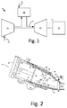
- Fig. 1 shows a schematic view of gas turbine engine 10 as may be used herein.
- the gas turbine engine 10 may include a compressor 15.
- the compressor 15 compresses an incoming flow of air 20.
- the compressor 15 delivers the compressed flow of air 20 to a combustor 25.
- the combustor 25 mixes the compressed flow of air 20 with a pressurized flow of fuel 30 and ignites the mixture to create a flow of combustion gases 35.
- the gas turbine engine 10 may include any number of the combustors 25 arranged in a circumferential array or otherwise.
- the flow of combustion gases 35 is delivered in turn to a turbine 40.
- the flow of combustion gases 35 drives the turbine 40 so as to produce mechanical work.
- the mechanical work produced in the turbine 40 drives the compressor 15 via a shaft 45 and an external load 50 such as an electrical generator and the like.
- the gas turbine engine 10 may use natural gas, liquid fuels, various types of syngas, and/or other types of fuels and blends thereof.
- the gas turbine engine 10 may be any one of a number of different gas turbine engines offered by General Electric Company of Schenectady, New York, including, but not limited to, those such as a 7 or a 9 series heavy duty gas turbine engine and the like.
- the gas turbine engine 10 may have different configurations and may use other types of components. Other types of gas turbine engines also may be used herein. Multiple gas turbine engines, other types of turbines, and other types of power generation equipment also may be used herein together.
- Fig. 2 shows an example of the combustor 25 that may be used with the gas turbine engine 10.
- the combustor 25 may extend from an end cover 52 at a head end to a transition piece 54 at an aft end about the turbine 40.
- a number of fuel nozzles 56 may be positioned about the end cover 52.
- a unibody liner 58 may extend from the fuel nozzles 56 towards the transition piece 54.
- the unibody liner 58 may define a primary combustion zone 60 therein.
- a flow sleeve 62 may surround the unibody liner 58.
- the unibody liner 58 and the flow sleeve 62 may define a flow path 64 therebetween for the flow of air 20 from the compressor 15 or from other sources.
- the combustor 15 also may include one or more late lean fuel injectors 66.
- the late lean fuel injectors 66 may extend radially through the flow sleeve 62 and the unibody liner 58 about a secondary combustion zone 68.
- the unibody liner 58 generally terminates about a first stage nozzle 70 of the turbine 40.
- Other components and other configurations may be used herein.
- the flow of air 20 from the compressor 15 may be routed through the flow path 64.
- a portion of the flow of air 20 may be directed to the head end of the combustor 25 so as to reverse direction and flow through the fuel nozzles 56.
- the flow of air 20 may be mixed with the flow of fuel 30 in the fuel nozzles 56 such that the air and fuel may be combusted in the primary combustion zone 60.
- a second portion of the flow of air 20 may be directed through the late lean injectors 66 where the air may be mixed with the fuel and ignited within the secondary combustion zone 68.
- the flow of the combustion gases 35 from the primary combustion zone 60 and the secondary combustion zone 68 may mix and flow towards the first stage 70 of the turbine 40 so as to produce useful work.
- the unibody liner 58 may include a main body 72.
- the main body 72 may have a substantially annular shape.
- the unibody 72 may include a forward end 74, an aft end 76, a generally conical portion 78, a fuel injection portion 80, and the transition piece 54 described above.
- the conical portion 78 may extend between the forward end 74 and the fuel injection portion 80.
- the transition piece 54 generally extends downstream from the fuel injection portion 80 and terminates about the aft end 76.
- the fuel injection portion 80 generally extends across the secondary combustion zone 68.
- the unibody liner 58 may include a number of fuel injection openings 82.
- the fuel injection openings 82 may be sized to accommodate the late lean fuel injector 66.
- a number of fuel injection bosses 84 may be positioned about the fuel injection openings 82 so as to position the late lean fuel injector 66 therein.
- the combustor 25 and the unibody liner 58 described herein are for the purpose of example only. Many other types of combustors and unibody liners may be known.
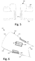
- Figs. 4-6 show an example of a portion of a combustor 100 as may be described herein.
- the combustor 100 may include a unibody liner 110.
- the unibody liner 110 may include a main body 120.
- the main body 120 may extend from a forward end 130 to an aft end 140.
- the main body 120 further may include a conical portion 150, a fuel injection portion 160, and a transition piece 170.
- the conical portion 150 may extend from the forward end 130 towards the fuel injection portion 160.
- the transition portion 170 may extend from the fuel injection portion 160 towards the aft end 140.
- the fuel injection portion 160 may include one or more fuel injection openings 180.
- Each of the fuel injection openings 180 may have a fuel injection boss 190 positioned therein.
- the fuel injection bosses 190 may be welded or otherwise secured within the fuel injection openings 180.
- a late lean fuel injector 66 and the like may be positioned within the fuel injection boss 190.
- Other components and other configurations may be used herein.
- the fuel injection portion 160 of the unibody liner 110 may extend into part or all of the transition piece 170.
- the fuel injection bosses 190 may be positioned within the transition piece 170 near the first stage nozzle 70 of the turbine 40. Such positioning may provide low combustion residence times therein given the proximity to the first stage 70 of the turbine 40.
- the fuel injection bosses 190 may include a highly contoured shape 200.
- the contoured shape 200 may include a downward flange 210 extending into the fuel injection opening 180.
- the downward flange 210 may define an injection boss opening 220 for the late lean fuel injector 66.
- the fuel injection bosses 190 also may include an outwardly projecting flange 230.
- the outwardly projecting flange 230 may extend along the flow sleeve 62 for support therewith.
- the fuel injection bosses 190, and the components thereof, may have any suitable size, shape, or configuration. Other components and other configurations may be used herein.
- the fuel injection bosses 190 may be manufactured in a Direct Metal Laser Melting ("DMLM") process.
- DMLM Direct Metal Laser Melting
- Laser scanning and the DMLM processes may provide the ability to create highly contoured and accurate shapes that may be easily welded to the unibody liner 110, particularly about the transition part 170. This positioning thus provides the very low late lean injection residence times. Moreover, this positioning benefits both single and multiple planes of late lean injection within the overall combustor 100.
- the use of DMLM thus permits the fuel injection bosses 180 to be positioned anywhere along the unibody liner 110.
Landscapes
- Engineering & Computer Science (AREA)
- Mechanical Engineering (AREA)
- Chemical & Material Sciences (AREA)
- Combustion & Propulsion (AREA)
- General Engineering & Computer Science (AREA)
- Physics & Mathematics (AREA)
- Optics & Photonics (AREA)
- Plasma & Fusion (AREA)
- Laser Beam Processing (AREA)
Abstract
Description
- The present application and the resultant patent relate generally to a gas turbine engine and more particularly relate to a gas turbine engine with an injection boss positioned on or about a transition piece of a unibody combustor liner for low combustion residence times.
- A combustion section of a gas turbine engine generally includes a number of combustors arranged in an annular array about a compressor discharge casing. A typical combustor may include an end cover coupled to the compressor discharge casing, an annular cap assembly that extends radially and axially within the compressor discharge casing, an annular liner that extends downstream from the cap assembly, and a transition piece that extends between the liner and a first stage of a turbine section. An aft frame portion of the transition piece may be coupled to the turbine casing for positioning and support.
- In an effort to decrease the number of individual components within the combustor of the gas turbine, the transition piece and the combustor liner may be combined into a unibody component. Late lean injectors may be positioned about the unibody liner. Due to limitations in the manufacturing processes, these injectors are currently position upstream of the transition piece. Such positioning, however, may increase the combustion residence time therein.
- There is thus a desire for an improved unibody liner for a combustor. Such an improved unibody liner may have increased flexibility in the positioning of the late lean injectors including positioning the injectors about the transition piece so as to provide very low late lean injection residence times for increased performance and lower emissions.
- The present application and the resultant patent thus provide a combustor. The combustor includes a unibody liner with a transition piece, a fuel injection portion, and a fuel injection opening. A fuel injection boss may be positioned within the fuel injection opening. The fuel injection boss may be manufactured in a direct metal laser melting process.
- The present application and the resultant patent further provide a method of manufacturing a combustor with low secondary combustion residence times. The method may include the steps of manufacturing a fuel injection boss in a direct metal laser melting process, positioning a fuel injection opening in a transition piece of a combustor liner, welding the fuel injection boss within the fuel injection opening, and positioning a late lean fuel injector in the fuel injection boss.
- The present application and the resultant patent further provide a combustor. The combustor may include a unibody liner with a transition piece, an overlapping fuel injection portion, and a fuel injection opening. A contoured fuel injection boss may be positioned within the fuel injection opening. The contoured fuel injection boss may be manufactured in a direct metal laser melting process.
- These and other features and improvements of the present application and the resultant patent will become apparent to one of ordinary skill in the art upon review of the following detailed description when taken in conjunction with the several drawings and the appended claims.
-
-
Fig. 1 is a schematic diagram of a gas turbine engine showing a compressor, a combustor, a turbine, and a load. -
Fig. 2 is a perspective view of a combustor that may be used with the gas turbine engine ofFig. 1 . -
Fig. 3 is a side view of a unibody liner that may be used with the combustor ofFig. 2 . -
Fig. 4 is a perspective view of a unibody liner as may be described herein with a DMLM formed injection boss. -
Fig. 5 is a sectional view of the DMLM formed injection boss ofFig. 4 . -
Fig. 6 is a perspective view of a unibody liner with an injection positioned within the DMLM injector boss. - Referring now to the drawings, in which like numerals refer to like elements throughout the several views,
Fig. 1 shows a schematic view ofgas turbine engine 10 as may be used herein. Thegas turbine engine 10 may include acompressor 15. Thecompressor 15 compresses an incoming flow ofair 20. Thecompressor 15 delivers the compressed flow ofair 20 to acombustor 25. Thecombustor 25 mixes the compressed flow ofair 20 with a pressurized flow offuel 30 and ignites the mixture to create a flow ofcombustion gases 35. Although only asingle combustor 25 is shown, thegas turbine engine 10 may include any number of thecombustors 25 arranged in a circumferential array or otherwise. The flow ofcombustion gases 35 is delivered in turn to aturbine 40. The flow ofcombustion gases 35 drives theturbine 40 so as to produce mechanical work. The mechanical work produced in theturbine 40 drives thecompressor 15 via ashaft 45 and anexternal load 50 such as an electrical generator and the like. - The
gas turbine engine 10 may use natural gas, liquid fuels, various types of syngas, and/or other types of fuels and blends thereof. Thegas turbine engine 10 may be any one of a number of different gas turbine engines offered by General Electric Company of Schenectady, New York, including, but not limited to, those such as a 7 or a 9 series heavy duty gas turbine engine and the like. Thegas turbine engine 10 may have different configurations and may use other types of components. Other types of gas turbine engines also may be used herein. Multiple gas turbine engines, other types of turbines, and other types of power generation equipment also may be used herein together. -
Fig. 2 shows an example of thecombustor 25 that may be used with thegas turbine engine 10. Generally described, thecombustor 25 may extend from anend cover 52 at a head end to atransition piece 54 at an aft end about theturbine 40. A number offuel nozzles 56 may be positioned about theend cover 52. Aunibody liner 58 may extend from thefuel nozzles 56 towards thetransition piece 54. Theunibody liner 58 may define aprimary combustion zone 60 therein. Aflow sleeve 62 may surround theunibody liner 58. Theunibody liner 58 and theflow sleeve 62 may define aflow path 64 therebetween for the flow ofair 20 from thecompressor 15 or from other sources. Thecombustor 15 also may include one or more latelean fuel injectors 66. The latelean fuel injectors 66 may extend radially through theflow sleeve 62 and theunibody liner 58 about asecondary combustion zone 68. Theunibody liner 58 generally terminates about afirst stage nozzle 70 of theturbine 40. Other components and other configurations may be used herein. - In use, the flow of
air 20 from thecompressor 15 may be routed through theflow path 64. A portion of the flow ofair 20 may be directed to the head end of thecombustor 25 so as to reverse direction and flow through thefuel nozzles 56. The flow ofair 20 may be mixed with the flow offuel 30 in thefuel nozzles 56 such that the air and fuel may be combusted in theprimary combustion zone 60. A second portion of the flow ofair 20 may be directed through the latelean injectors 66 where the air may be mixed with the fuel and ignited within thesecondary combustion zone 68. The flow of thecombustion gases 35 from theprimary combustion zone 60 and thesecondary combustion zone 68 may mix and flow towards thefirst stage 70 of theturbine 40 so as to produce useful work. -
Fig. 3 shows an example of theunibody liner 58. Generally described, theunibody liner 58 may include amain body 72. Themain body 72 may have a substantially annular shape. Theunibody 72 may include aforward end 74, anaft end 76, a generallyconical portion 78, afuel injection portion 80, and thetransition piece 54 described above. Theconical portion 78 may extend between theforward end 74 and thefuel injection portion 80. Thetransition piece 54 generally extends downstream from thefuel injection portion 80 and terminates about theaft end 76. Thefuel injection portion 80 generally extends across thesecondary combustion zone 68. - The
unibody liner 58 may include a number offuel injection openings 82. Thefuel injection openings 82 may be sized to accommodate the latelean fuel injector 66. A number of fuel injection bosses 84 may be positioned about thefuel injection openings 82 so as to position the latelean fuel injector 66 therein. Thecombustor 25 and theunibody liner 58 described herein are for the purpose of example only. Many other types of combustors and unibody liners may be known. -
Figs. 4-6 show an example of a portion of acombustor 100 as may be described herein. Thecombustor 100 may include aunibody liner 110. In a manner similar to that described above, theunibody liner 110 may include amain body 120. Themain body 120 may extend from aforward end 130 to anaft end 140. Themain body 120 further may include aconical portion 150, afuel injection portion 160, and atransition piece 170. Theconical portion 150 may extend from theforward end 130 towards thefuel injection portion 160. Likewise, thetransition portion 170 may extend from thefuel injection portion 160 towards theaft end 140. Thefuel injection portion 160 may include one or morefuel injection openings 180. Each of thefuel injection openings 180 may have afuel injection boss 190 positioned therein. Thefuel injection bosses 190 may be welded or otherwise secured within thefuel injection openings 180. A latelean fuel injector 66 and the like may be positioned within thefuel injection boss 190. Other components and other configurations may be used herein. - In this example, the
fuel injection portion 160 of theunibody liner 110 may extend into part or all of thetransition piece 170. Specifically, thefuel injection bosses 190 may be positioned within thetransition piece 170 near thefirst stage nozzle 70 of theturbine 40. Such positioning may provide low combustion residence times therein given the proximity to thefirst stage 70 of theturbine 40. - The
fuel injection bosses 190 may include a highly contoured shape 200. The contoured shape 200 may include adownward flange 210 extending into the fuel injection opening 180. Thedownward flange 210 may define an injection boss opening 220 for the latelean fuel injector 66. Thefuel injection bosses 190 also may include an outwardly projectingflange 230. The outwardly projectingflange 230 may extend along theflow sleeve 62 for support therewith. Thefuel injection bosses 190, and the components thereof, may have any suitable size, shape, or configuration. Other components and other configurations may be used herein. - The
fuel injection bosses 190 may be manufactured in a Direct Metal Laser Melting ("DMLM") process. Laser scanning and the DMLM processes may provide the ability to create highly contoured and accurate shapes that may be easily welded to theunibody liner 110, particularly about thetransition part 170. This positioning thus provides the very low late lean injection residence times. Moreover, this positioning benefits both single and multiple planes of late lean injection within theoverall combustor 100. The use of DMLM thus permits thefuel injection bosses 180 to be positioned anywhere along theunibody liner 110. - It should be apparent that the foregoing relates only to certain embodiments of the present application and the resultant patent. Numerous changes and modifications may be made herein by one of ordinary skill in the art without departing from the general spirit and scope of the invention as defined by the following claims and the equivalents thereof.
- Various aspects and embodiments of the present invention are defined by the following numbered clauses:
- 1. A combustor, comprising:
- a unibody liner;
- the unibody liner comprising a transition piece, a fuel injection portion, and a fuel injection opening; and
- a fuel injection boss positioned within the fuel injection opening;
- wherein the fuel injection boss is manufactured in a direct metal laser melting process.
- 2. The combustor of clause 1, wherein the fuel injection portion overlaps the transition piece in whole or in part.
- 3. The combustor of any preceding clause, wherein the fuel injection opening is positioned within the transition piece.
- 4. The combustor of any preceding clause, further comprising a plurality of fuel injection openings and fuel injection bosses.
- 5. The combustor of any preceding clause, wherein the unibody liner comprises a forward end and an aft end.
- 6. The combustor of any preceding clause, wherein the unibody liner comprises a conical portion about the forward end and the transition piece about the aft end.
- 7. The combustor of any preceding clause, wherein the transition piece is positioned about a first turbine stage.
- 8. The combustor of any preceding clause, wherein the fuel injection boss comprises a contoured shape.
- 9. The combustor of any preceding clause, wherein the fuel injection boss comprises a downward flange and an outwardly extending flange.
- 10. The combustor of any preceding clause, wherein the downwardly extending flange defines a fuel injection boss opening.
- 11. The combustor of any preceding clause, further comprising a fuel injector positioned within the fuel injection boss.
- 12. The combustor of any preceding clause, wherein the fuel injector is positioned about a secondary combustion zone.
- 13. The combustor of any preceding clause, wherein the fuel injector comprises a late lean fuel injector.
- 14. The combustor of any preceding clause, further comprising a flow sleeve surrounding the unibody liner and defining a flow path therethrough.
- 15. A method of manufacturing a combustor with low secondary combustion residence times, comprising:
- manufacturing a fuel injection boss in a direct metal laser melting process;
- positioning a fuel injection opening in a transition piece of a combustor liner;
- welding the fuel injection boss within the fuel injection opening; and
- positioning a late lean fuel injector in the fuel injection boss.
- 16. A combustor, comprising:
- a unibody liner;
- the unibody liner comprising a transition piece, a fuel injection portion, and a fuel injection opening;
- wherein the fuel injection portion overlaps the transition piece; and
- a contoured fuel injection boss positioned within the fuel injection opening;
- wherein the contoured fuel injection boss is manufactured in a direct metal laser melting process.
- 17. The combustor of any preceding clause, wherein the fuel injection opening is positioned within the transition piece.
- 18. The combustor of any preceding clause, further comprising a plurality of fuel injection openings and fuel injection bosses.
- 19. The combustor of any preceding clause, wherein the fuel injection boss comprises a downward flange, an outwardly extending flange, and wherein the downwardly extending flange defines a fuel injection boss opening.
- 20. The combustor of any preceding clause, further comprising a fuel injector positioned within the fuel injection boss.
Claims (15)
- A combustor, comprising:a unibody liner;the unibody liner comprising a transition piece, a fuel injection portion, and a fuel injection opening; anda fuel injection boss positioned within the fuel injection opening;wherein the fuel injection boss is manufactured in a direct metal laser melting process.
- The combustor of claim 1, wherein the fuel injection portion overlaps the transition piece in whole or in part.
- The combustor of claim 1, wherein the fuel injection opening is positioned within the transition piece.
- The combustor of claim 1, 2 or 3, further comprising a plurality of fuel injection openings and fuel injection bosses.
- The combustor of any preceding claim, wherein the unibody liner comprises a forward end and an aft end.
- The combustor of claim 5, wherein the unibody liner comprises a conical portion about the forward end and the transition piece about the aft end.
- The combustor of any preceding claim, wherein the transition piece is positioned about a first turbine stage.
- The combustor of any preceding claim, wherein the fuel injection boss comprises a contoured shape.
- The combustor of any of claims 1 to 7, wherein the fuel injection boss comprises a downward flange and an outwardly extending flange.
- The combustor of claim 9, wherein the downwardly extending flange defines a fuel injection boss opening.
- The combustor of any preceding claim, further comprising a fuel injector positioned within the fuel injection boss.
- The combustor of claim 11, wherein the fuel injector is positioned about a secondary combustion zone.
- The combustor of claim 11, wherein the fuel injector comprises a late lean fuel injector.
- The combustor of any preceding claim, further comprising a flow sleeve surrounding the unibody liner and defining a flow path therethrough.
- A method of manufacturing a combustor with low secondary combustion residence times, comprising:manufacturing a fuel injection boss in a direct metal laser melting process;positioning a fuel injection opening in a transition piece of a combustor liner;welding the fuel injection boss within the fuel injection opening; andpositioning a late lean fuel injector in the fuel injection boss.
Applications Claiming Priority (1)
| Application Number | Priority Date | Filing Date | Title |
|---|---|---|---|
| US14/666,358 US20160281992A1 (en) | 2015-03-24 | 2015-03-24 | Injection boss for a unibody combustor |
Publications (1)
| Publication Number | Publication Date |
|---|---|
| EP3098516A1 true EP3098516A1 (en) | 2016-11-30 |
Family
ID=55542562
Family Applications (1)
| Application Number | Title | Priority Date | Filing Date |
|---|---|---|---|
| EP16160819.5A Withdrawn EP3098516A1 (en) | 2015-03-24 | 2016-03-17 | Injection boss for a unibody combustor |
Country Status (4)
| Country | Link |
|---|---|
| US (1) | US20160281992A1 (en) |
| EP (1) | EP3098516A1 (en) |
| JP (1) | JP2016180584A (en) |
| CN (1) | CN106016359A (en) |
Cited By (2)
| Publication number | Priority date | Publication date | Assignee | Title |
|---|---|---|---|---|
| US11156164B2 (en) | 2019-05-21 | 2021-10-26 | General Electric Company | System and method for high frequency accoustic dampers with caps |
| US11174792B2 (en) | 2019-05-21 | 2021-11-16 | General Electric Company | System and method for high frequency acoustic dampers with baffles |
Families Citing this family (5)
| Publication number | Priority date | Publication date | Assignee | Title |
|---|---|---|---|---|
| EP3325887A1 (en) * | 2015-07-24 | 2018-05-30 | Siemens Aktiengesellschaft | Gas turbine transition duct with late lean injection having reduced combustion residence time |
| US11067281B1 (en) * | 2020-09-25 | 2021-07-20 | General Electric Company | Fuel injection assembly for a turbomachine combustor |
| US11333360B2 (en) * | 2020-09-25 | 2022-05-17 | General Electric Company | Fuel injector for a turbomachine |
| US12270543B2 (en) | 2021-08-20 | 2025-04-08 | Rtx Corporation | Multi-function monolithic combustion liner |
| US20250216076A1 (en) * | 2023-12-29 | 2025-07-03 | Ge Infrastructure Technology Llc | Additively manufactured combustor body with resonating tube |
Citations (5)
| Publication number | Priority date | Publication date | Assignee | Title |
|---|---|---|---|---|
| US20140250917A1 (en) * | 2013-03-08 | 2014-09-11 | Rolls-Royce Plc | Combustion chamber heat shield and seal assembly and a method of manufacturing a combustion chamber heat shield and seal assembly |
| US20140260264A1 (en) * | 2013-03-18 | 2014-09-18 | General Electric Company | System for controlling a flow rate of a compressed working fluid to a combustor fuel injector |
| US20140260273A1 (en) * | 2013-03-18 | 2014-09-18 | General Electric Company | Continuous combustion liner for a combustor of a gas turbine |
| WO2014160299A1 (en) * | 2013-03-14 | 2014-10-02 | United Technologies Corporation | Combustor panel with increased durability |
| WO2014189602A2 (en) * | 2013-03-14 | 2014-11-27 | United Technologies Corporation | Hollow-wall heat shield for fuel injector component |
Family Cites Families (10)
| Publication number | Priority date | Publication date | Assignee | Title |
|---|---|---|---|---|
| US7082766B1 (en) * | 2005-03-02 | 2006-08-01 | General Electric Company | One-piece can combustor |
| GB0616116D0 (en) * | 2006-08-12 | 2006-09-20 | Rolls Royce Plc | A method of forming a component on a substrate |
| US8387398B2 (en) * | 2007-09-14 | 2013-03-05 | Siemens Energy, Inc. | Apparatus and method for controlling the secondary injection of fuel |
| JP2010085052A (en) * | 2008-10-01 | 2010-04-15 | Mitsubishi Heavy Ind Ltd | Combustor tail pipe, designing method therefor, and gas turbine |
| US8683808B2 (en) * | 2009-01-07 | 2014-04-01 | General Electric Company | Late lean injection control strategy |
| US8201412B2 (en) * | 2010-09-13 | 2012-06-19 | General Electric Company | Apparatus and method for cooling a combustor |
| US8919137B2 (en) * | 2011-08-05 | 2014-12-30 | General Electric Company | Assemblies and apparatus related to integrating late lean injection into combustion turbine engines |
| US8407892B2 (en) * | 2011-08-05 | 2013-04-02 | General Electric Company | Methods relating to integrating late lean injection into combustion turbine engines |
| EP2742291B1 (en) * | 2011-08-11 | 2020-07-08 | General Electric Company | System for injecting fuel in a gas turbine engine |
| US9303872B2 (en) * | 2011-09-15 | 2016-04-05 | General Electric Company | Fuel injector |
-
2015
- 2015-03-24 US US14/666,358 patent/US20160281992A1/en not_active Abandoned
-
2016
- 2016-03-16 JP JP2016051792A patent/JP2016180584A/en active Pending
- 2016-03-17 EP EP16160819.5A patent/EP3098516A1/en not_active Withdrawn
- 2016-03-24 CN CN201610172086.5A patent/CN106016359A/en active Pending
Patent Citations (5)
| Publication number | Priority date | Publication date | Assignee | Title |
|---|---|---|---|---|
| US20140250917A1 (en) * | 2013-03-08 | 2014-09-11 | Rolls-Royce Plc | Combustion chamber heat shield and seal assembly and a method of manufacturing a combustion chamber heat shield and seal assembly |
| WO2014160299A1 (en) * | 2013-03-14 | 2014-10-02 | United Technologies Corporation | Combustor panel with increased durability |
| WO2014189602A2 (en) * | 2013-03-14 | 2014-11-27 | United Technologies Corporation | Hollow-wall heat shield for fuel injector component |
| US20140260264A1 (en) * | 2013-03-18 | 2014-09-18 | General Electric Company | System for controlling a flow rate of a compressed working fluid to a combustor fuel injector |
| US20140260273A1 (en) * | 2013-03-18 | 2014-09-18 | General Electric Company | Continuous combustion liner for a combustor of a gas turbine |
Cited By (2)
| Publication number | Priority date | Publication date | Assignee | Title |
|---|---|---|---|---|
| US11156164B2 (en) | 2019-05-21 | 2021-10-26 | General Electric Company | System and method for high frequency accoustic dampers with caps |
| US11174792B2 (en) | 2019-05-21 | 2021-11-16 | General Electric Company | System and method for high frequency acoustic dampers with baffles |
Also Published As
| Publication number | Publication date |
|---|---|
| CN106016359A (en) | 2016-10-12 |
| US20160281992A1 (en) | 2016-09-29 |
| JP2016180584A (en) | 2016-10-13 |
Similar Documents
| Publication | Publication Date | Title |
|---|---|---|
| EP3098516A1 (en) | Injection boss for a unibody combustor | |
| EP2626635B1 (en) | Combustor assembly with trapped vortex cavity | |
| EP3341656B1 (en) | Fuel nozzle assembly for a gas turbine | |
| CN106016365B (en) | System and method for creating a seal around a liquid fuel injector | |
| US20190170355A1 (en) | Fuel injector | |
| US8733108B2 (en) | Combustor and combustor screech mitigation methods | |
| EP3220047A1 (en) | Gas turbine flow sleeve mounting | |
| EP2813763A1 (en) | A fuel injector and a combustion chamber | |
| EP3312510A1 (en) | Combustor assembly with air shield for a radial fuel injector | |
| US9989254B2 (en) | Combustor leakage control system | |
| EP3220053A1 (en) | Axially staged fuel injector assembly and method of mounting | |
| US9696037B2 (en) | Liner retaining feature for a combustor | |
| EP2505921B1 (en) | Combustor crossfire tube having purge holes | |
| US20170356652A1 (en) | Combustor Effusion Plate Assembly | |
| US9145778B2 (en) | Combustor with non-circular head end | |
| EP2578940A2 (en) | Combustor and method for supplying flow to a combustor | |
| EP2618052A1 (en) | Fuel Nozzle | |
| US9528703B2 (en) | Micro-mixer fuel plenum and methods for fuel tube installation | |
| EP3586062B1 (en) | Combustion system with axially staged fuel injection | |
| US9175855B2 (en) | Combustion nozzle with floating aft plate | |
| US9500367B2 (en) | Combustion casing manifold for high pressure air delivery to a fuel nozzle pilot system |
Legal Events
| Date | Code | Title | Description |
|---|---|---|---|
| PUAI | Public reference made under article 153(3) epc to a published international application that has entered the european phase |
Free format text: ORIGINAL CODE: 0009012 |
|
| AK | Designated contracting states |
Kind code of ref document: A1 Designated state(s): AL AT BE BG CH CY CZ DE DK EE ES FI FR GB GR HR HU IE IS IT LI LT LU LV MC MK MT NL NO PL PT RO RS SE SI SK SM TR |
|
| AX | Request for extension of the european patent |
Extension state: BA ME |
|
| 17P | Request for examination filed |
Effective date: 20170530 |
|
| RBV | Designated contracting states (corrected) |
Designated state(s): AL AT BE BG CH CY CZ DE DK EE ES FI FR GB GR HR HU IE IS IT LI LT LU LV MC MK MT NL NO PL PT RO RS SE SI SK SM TR |
|
| STAA | Information on the status of an ep patent application or granted ep patent |
Free format text: STATUS: THE APPLICATION IS DEEMED TO BE WITHDRAWN |
|
| 18D | Application deemed to be withdrawn |
Effective date: 20191001 |