EP3098467A1 - Roller bearing device - Google Patents
Roller bearing device Download PDFInfo
- Publication number
- EP3098467A1 EP3098467A1 EP15740447.6A EP15740447A EP3098467A1 EP 3098467 A1 EP3098467 A1 EP 3098467A1 EP 15740447 A EP15740447 A EP 15740447A EP 3098467 A1 EP3098467 A1 EP 3098467A1
- Authority
- EP
- European Patent Office
- Prior art keywords
- lubrication oil
- spacer
- rolling bearing
- bag
- oil tank
- Prior art date
- Legal status (The legal status is an assumption and is not a legal conclusion. Google has not performed a legal analysis and makes no representation as to the accuracy of the status listed.)
- Withdrawn
Links
- 238000005461 lubrication Methods 0.000 claims abstract description 59
- 125000006850 spacer group Chemical group 0.000 claims abstract description 55
- 238000005096 rolling process Methods 0.000 claims abstract description 50
- 239000011347 resin Substances 0.000 claims description 23
- 229920005989 resin Polymers 0.000 claims description 23
- 238000003466 welding Methods 0.000 claims description 9
- 238000010030 laminating Methods 0.000 claims description 4
- 239000002184 metal Substances 0.000 abstract description 5
- 229910052751 metal Inorganic materials 0.000 abstract description 5
- 239000003921 oil Substances 0.000 description 65
- 239000004020 conductor Substances 0.000 description 13
- 238000009413 insulation Methods 0.000 description 12
- 239000000758 substrate Substances 0.000 description 12
- 239000000463 material Substances 0.000 description 6
- RYGMFSIKBFXOCR-UHFFFAOYSA-N Copper Chemical compound [Cu] RYGMFSIKBFXOCR-UHFFFAOYSA-N 0.000 description 4
- XEEYBQQBJWHFJM-UHFFFAOYSA-N Iron Chemical group [Fe] XEEYBQQBJWHFJM-UHFFFAOYSA-N 0.000 description 4
- 239000000853 adhesive Substances 0.000 description 4
- 230000001070 adhesive effect Effects 0.000 description 4
- 239000003990 capacitor Substances 0.000 description 4
- 229910052802 copper Inorganic materials 0.000 description 4
- 239000010949 copper Substances 0.000 description 4
- 230000004907 flux Effects 0.000 description 4
- 239000004519 grease Substances 0.000 description 4
- 230000005678 Seebeck effect Effects 0.000 description 3
- 230000015572 biosynthetic process Effects 0.000 description 3
- 229920001971 elastomer Polymers 0.000 description 3
- 239000004615 ingredient Substances 0.000 description 3
- 238000003860 storage Methods 0.000 description 3
- 239000004952 Polyamide Substances 0.000 description 2
- 238000007599 discharging Methods 0.000 description 2
- 230000005674 electromagnetic induction Effects 0.000 description 2
- 239000004744 fabric Substances 0.000 description 2
- 238000004519 manufacturing process Methods 0.000 description 2
- 229920002647 polyamide Polymers 0.000 description 2
- -1 polyethylene Polymers 0.000 description 2
- 244000025254 Cannabis sativa Species 0.000 description 1
- 235000012766 Cannabis sativa ssp. sativa var. sativa Nutrition 0.000 description 1
- 235000012765 Cannabis sativa ssp. sativa var. spontanea Nutrition 0.000 description 1
- 229910000881 Cu alloy Inorganic materials 0.000 description 1
- YCKRFDGAMUMZLT-UHFFFAOYSA-N Fluorine atom Chemical compound [F] YCKRFDGAMUMZLT-UHFFFAOYSA-N 0.000 description 1
- 229920000571 Nylon 11 Polymers 0.000 description 1
- 229920000299 Nylon 12 Polymers 0.000 description 1
- 239000004698 Polyethylene Substances 0.000 description 1
- 239000004743 Polypropylene Substances 0.000 description 1
- 102100026827 Protein associated with UVRAG as autophagy enhancer Human genes 0.000 description 1
- 101710102978 Protein associated with UVRAG as autophagy enhancer Proteins 0.000 description 1
- BQCADISMDOOEFD-UHFFFAOYSA-N Silver Chemical compound [Ag] BQCADISMDOOEFD-UHFFFAOYSA-N 0.000 description 1
- 239000002199 base oil Substances 0.000 description 1
- 235000009120 camo Nutrition 0.000 description 1
- 235000005607 chanvre indien Nutrition 0.000 description 1
- 238000005520 cutting process Methods 0.000 description 1
- 238000010586 diagram Methods 0.000 description 1
- 230000000694 effects Effects 0.000 description 1
- 239000000806 elastomer Substances 0.000 description 1
- 239000003822 epoxy resin Substances 0.000 description 1
- 239000011737 fluorine Substances 0.000 description 1
- 229910052731 fluorine Inorganic materials 0.000 description 1
- PCHJSUWPFVWCPO-UHFFFAOYSA-N gold Chemical compound [Au] PCHJSUWPFVWCPO-UHFFFAOYSA-N 0.000 description 1
- 229910052737 gold Inorganic materials 0.000 description 1
- 239000010931 gold Substances 0.000 description 1
- 239000011487 hemp Substances 0.000 description 1
- 230000006698 induction Effects 0.000 description 1
- 230000003993 interaction Effects 0.000 description 1
- 238000000034 method Methods 0.000 description 1
- 239000000088 plastic resin Substances 0.000 description 1
- 230000010287 polarization Effects 0.000 description 1
- 229920000647 polyepoxide Polymers 0.000 description 1
- 229920000728 polyester Polymers 0.000 description 1
- 229920000573 polyethylene Polymers 0.000 description 1
- 229920001155 polypropylene Polymers 0.000 description 1
- 229920001296 polysiloxane Polymers 0.000 description 1
- 238000010248 power generation Methods 0.000 description 1
- 230000005855 radiation Effects 0.000 description 1
- 229910052709 silver Inorganic materials 0.000 description 1
- 239000004332 silver Substances 0.000 description 1
Images






Classifications
-
- F—MECHANICAL ENGINEERING; LIGHTING; HEATING; WEAPONS; BLASTING
- F16—ENGINEERING ELEMENTS AND UNITS; GENERAL MEASURES FOR PRODUCING AND MAINTAINING EFFECTIVE FUNCTIONING OF MACHINES OR INSTALLATIONS; THERMAL INSULATION IN GENERAL
- F16C—SHAFTS; FLEXIBLE SHAFTS; ELEMENTS OR CRANKSHAFT MECHANISMS; ROTARY BODIES OTHER THAN GEARING ELEMENTS; BEARINGS
- F16C33/00—Parts of bearings; Special methods for making bearings or parts thereof
- F16C33/30—Parts of ball or roller bearings
- F16C33/66—Special parts or details in view of lubrication
- F16C33/6637—Special parts or details in view of lubrication with liquid lubricant
- F16C33/664—Retaining the liquid in or near the bearing
-
- F—MECHANICAL ENGINEERING; LIGHTING; HEATING; WEAPONS; BLASTING
- F16—ENGINEERING ELEMENTS AND UNITS; GENERAL MEASURES FOR PRODUCING AND MAINTAINING EFFECTIVE FUNCTIONING OF MACHINES OR INSTALLATIONS; THERMAL INSULATION IN GENERAL
- F16C—SHAFTS; FLEXIBLE SHAFTS; ELEMENTS OR CRANKSHAFT MECHANISMS; ROTARY BODIES OTHER THAN GEARING ELEMENTS; BEARINGS
- F16C19/00—Bearings with rolling contact, for exclusively rotary movement
- F16C19/02—Bearings with rolling contact, for exclusively rotary movement with bearing balls essentially of the same size in one or more circular rows
- F16C19/14—Bearings with rolling contact, for exclusively rotary movement with bearing balls essentially of the same size in one or more circular rows for both radial and axial load
- F16C19/16—Bearings with rolling contact, for exclusively rotary movement with bearing balls essentially of the same size in one or more circular rows for both radial and axial load with a single row of balls
- F16C19/163—Bearings with rolling contact, for exclusively rotary movement with bearing balls essentially of the same size in one or more circular rows for both radial and axial load with a single row of balls with angular contact
-
- F—MECHANICAL ENGINEERING; LIGHTING; HEATING; WEAPONS; BLASTING
- F16—ENGINEERING ELEMENTS AND UNITS; GENERAL MEASURES FOR PRODUCING AND MAINTAINING EFFECTIVE FUNCTIONING OF MACHINES OR INSTALLATIONS; THERMAL INSULATION IN GENERAL
- F16C—SHAFTS; FLEXIBLE SHAFTS; ELEMENTS OR CRANKSHAFT MECHANISMS; ROTARY BODIES OTHER THAN GEARING ELEMENTS; BEARINGS
- F16C33/00—Parts of bearings; Special methods for making bearings or parts thereof
- F16C33/30—Parts of ball or roller bearings
- F16C33/66—Special parts or details in view of lubrication
- F16C33/6637—Special parts or details in view of lubrication with liquid lubricant
- F16C33/6659—Details of supply of the liquid to the bearing, e.g. passages or nozzles
-
- F—MECHANICAL ENGINEERING; LIGHTING; HEATING; WEAPONS; BLASTING
- F16—ENGINEERING ELEMENTS AND UNITS; GENERAL MEASURES FOR PRODUCING AND MAINTAINING EFFECTIVE FUNCTIONING OF MACHINES OR INSTALLATIONS; THERMAL INSULATION IN GENERAL
- F16C—SHAFTS; FLEXIBLE SHAFTS; ELEMENTS OR CRANKSHAFT MECHANISMS; ROTARY BODIES OTHER THAN GEARING ELEMENTS; BEARINGS
- F16C41/00—Other accessories, e.g. devices integrated in the bearing not relating to the bearing function as such
- F16C41/004—Electro-dynamic machines, e.g. motors, generators, actuators
Definitions
- the present invention relates to rolling bearing devices used in machine tools, industrial machinery, etc., and particularly to a rolling bearing device constituted as a combination of a rolling bearing and an oil supply unit.
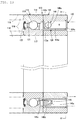
- a rolling bearing device 110 is shown in Fig. 13 , which is composed of a rolling bearing 111; a spacer 112 contacted to an axial end thereof; and an oil supply unit 113 incorporated in the spacer 112 (Patent Literature 1).
- the rolling bearing device 110 is assembled between a rotation shaft 114 and a housing 115 when utilized.
- the rolling bearing 111 has another end contacted by another spacer 116. Both of the spacers 112, 116 determine an axial position of the rolling bearing 111.
- the rolling bearing 111 is provided by an angular contact ball bearing or a deep groove ball bearing, and includes: an inner ring 117 serving as a rotating track ring; an outer ring 118 serving as a fixed one; a predetermined number of rolling elements 119 placed between these track rings; and a retainer 121 which keeps these rolling elements 119 at a constant distance from each other.
- the rolling bearing 111 is pre-packed with a desirable type of grease, and an end on the spacer 116 side has a seal plate 122 attached thereto.
- the spacer 112 includes an inner-ring-side spacer 112a and an outer-ring-side spacer 112b.
- the inner-ring-side spacer 112a is fitted in and fixed to the rotation shaft 114 side and is contacted onto an end surface of the inner ring 117.
- the outer-ring-side spacer 112b is fitted in and fixed to an inner diameter surface of the housing 115, and is contacted onto an end surface of the outer ring 118.
- the other spacer 116 is also fitted in and fixed to the rotation shaft 114 side and the housing 115 side in the same fashion, and is contacted onto the other end surfaces of the inner ring 17 and of the outer ring 118.
- the oil supply unit 113 includes an annular housing 124 and various components housed therein in a circumferential direction.
- the components include a generator section 141, a charging section 142, a controller 143, a driving section 144, a pump 145, a lubrication oil tank 146, and others.
- Patent Literature 1 JP-A 2013-60999 Gazette
- the lubrication oil tank 146 is housed in a housing main body 124a, is provided by a bag, and is disposed in an arc shape along the annular housing 124.
- the arc-shaped bag 146a is made, for instance, by first laminating two sheets 146b, 146b which are cut into an arc-like shape, and then as shown in Fig. 16 , thermally welding an outer perimeter of the two mutually laminated sheets 146b, 146b. Note that the thermally welded region is indicated by a reference symbol 146c and is cross-hatched in Fig. 16 .
- Another problem is that making the lubrication oil tank 146, i.e., the arc-shaped resin bag 146a, requires cutting of the sheets into the arc shape, and performing thermal welding, which requires an arc-shaped metal mold that follows a specific arc shape, for each of the bearing size.
- the present invention provides a rolling bearing device comprising a combination of a rolling bearing and an oil supply unit which includes at least: a lubrication oil tank having a lubrication oil discharge port, a pump; a driving section; an electric power source section; and a controller.
- the oil supply unit is between an inner ring and an outer ring of a spacer adjacent to the rolling bearing.
- a space for the lubrication oil tank in the oil supply unit has a width equal to an axial width of the spacer and is within a range of a center angle ⁇ in an axial view of the spacer; and the lubrication oil tank in the oil supply unit is provided by a bag which has a width equal to an axial width of the spacer and a length equal to A ⁇ ( ⁇ /360), where A represents a center diameter of the spacer.
- the lubrication oil tank is a rectangular, elastic bag which has approximately the same width as the axial width of the housing space and approximately the same length as the length given by A ⁇ ( ⁇ /360), where A represents a center diameter of the spacer, there is no dead space in the housing space, i.e., the housing space is effectively utilized.
- the rectangular bag can be made, for example, by laminating two strip-like sheets and then bonding four perimeter sides of the laminated sheets straightly, or by folding a strip-like sheets which has two times the width of the spacer and then bonding three perimeter sides of the folded sheet straightly.
- the bag which serves as the lubrication oil tank may be made of any material such as woven cloth of hemp for example; resin; woven cloth coated with resin or rubber, or others.
- resin is a preferred material due to its ease of handling and manufacture, as well as cost.
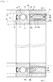
- a rolling bearing device 10 according to an embodiment shown in Fig. 1 through Fig. 3 includes a rolling bearing 11; a spacer 12 contacted onto an axial end of the rolling bearing; and an oil supply unit 13 incorporated in the spacer 12; and when used, is assembled into a space between a rotation shaft 14 and a housing 15.
- the rolling bearing 11 has another end, on which another spacer 16 is contacted. These two spacers 12, 16 provide axial positioning of the rolling bearing 11.
- the rotation shaft 14 in this embodiment is horizontal.
- the rolling bearing 11 may be provided by whichever of an angular contact ball bearing and a deep groove roller bearing, and includes a rotation-side track ring provided by an inner ring 17; an outer ring 18 on a fixed side; a predetermined number of rolling elements 19 placed between these track rings; and a retainer 21 which keeps a predetermined distance between the rolling elements 19.
- the rolling bearing 11 is pre-packed with desirable grease, and a seal plate 22 is attached to an end on the spacer 16 side.
- the spacer 12 includes an inner-ring-side spacer 12a and an outer-ring-side spacer 12b.
- the inner-ring-side spacer 12a is fitted in and fixed to the rotation shaft 14 side and is contacted onto an end surface of the inner ring 17.
- the outer-ring-side spacer 12b is fitted in and fixed to an inner diameter surface of the housing 15, and is contacted onto an end surface of the outer ring 18.
- the other spacer 16 is also fitted in and fixed to the rotation shaft 14 side and the housing 15 side in the same fashion, and is contacted onto the other end surfaces of the inner ring 17 and of the outer ring 18.
- the oil supply unit 13 includes an annular housing 24 and various components housed therein in a circumferential direction.
- the components include a generator section 41, a charging section 42, a controller section 43, a driving section 44, a pump 45, a lubrication oil tank 46 and so on.
- the annular housing 24 of the oil supply unit 13 is an assembly of a housing main body 24a which has a generally U-shaped section with an open end facing away from the rolling bearing 11; and a lid 24b which closes the open end of the housing main body 24a and is detachable from/attachable to the housing main body 24a.
- the housing main body 24a and the lid 24b are made of the same thermally plastic resin material such as PPS.
- the lid 24b of the housing 24 is fixed to the housing main body 24a using screws 24c. By unscrewing the screws 24c and removing the lid 24b, it becomes possible to replenish the lubrication oil tank 46 housed inside the housing main body 24a with lubrication oil, without removing the entire oil supply unit 13.
- the housing main body 24a has its outer circumferential surface adhesively fixed to an inner diameter surface of the outer-ring-side spacer 12b.
- the adhesive for fixing the housing main body 24a may be provided by epoxy resin for example.
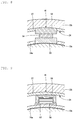
- Fig. 4 shows an embodiment in which the housing 24 is fixed to the inner diameter surface of the outer-ring-side spacer 12b without using an adhesive.
- a pair of recesses 12c, 12d receding in an outer diameter direction are formed on both axial sides of an inner diameter surface of the outer ring-side spacer 12b;
- the housing main body 24a has an outer diameter surface on the rolling bearing 11 side, where there is formed a ridge 24d to fit into the recess 12c, and this ridge 24d is fitted into the recess 12c;
- the other recess 12d is fitted by an outer diameter portion of the lid 24b which is fixed to the housing main body 24a with the screws 24c, so that the lid 24b is screw-fixed to the housing main body 24a by the screws 24c.
- the inner diameter surface of the outer ring-side spacer 12b is sandwiched by the ridge 24d of the housing main body 24a and the outer diameter portion of the lid 24b, thereby fixing the housing 24 to the inner diameter surface of the outer ring-side spacer 12b, without using an adhesive.
- the lubrication oil tank 46 inside the housing main body 24a is provided by a bag 46a of an elastic resin, and is disposed in an arcuate form along the annular housing 24.
- the resin bag 46a can be made by first laminating two strip-like resin sheets 46b, 46b each having an approximately the same width as a width L of the housing main body 24a and the same length as a circumferential length of a housing space for the bag 46a in the housing main body 24a, the length specifically being given by A ⁇ ( ⁇ /360), where A representing a center diameter of the spacer 12, and ⁇ representing a center angle ( ⁇ °) of the pacer 12 of the housing space for the bag 46a; and then thermally welding four outer perimeter sides of the sheets straightly as shown in Fig. 5(b) .
- a reference symbol 46c indicates the thermally welded region.
- Fig. 6 (a) shows another example: A strip-like resin sheet 46b, having a width which is two times the width L of the housing main body 24a is two-folded, and then as shown in Fig. 6(b) , three perimeter sides are thermally welded straightly.
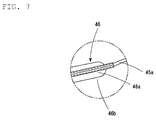
- the bag 46a is provided with a suction tube 45a which leads to the pump 45.
- the suction tube 45a can be integrated with the bag 46a by sandwiching the tube between two sheets of resin for forming the bag 46a and then performing the thermal welding to complete the bag 46a.
- the bag 46a which constitutes the lubrication oil tank 46 can be formed of such a material as polyamide (for example, polyamide 11 and polyamide 12), fluorine-containing rubber (FKM), polyamide elastomer, polyethylene, polyester and polypropylene.
- polyamide for example, polyamide 11 and polyamide 12
- FKM fluorine-containing rubber
- polyamide elastomer polyethylene
- polyester polyester
- polypropylene There is no specific limitation to the material as far as the material is compatible with lubrication oil stored in the bag 46a.
- the suction tube 45a which is provided in the bag 46a of the lubrication oil tank 46 is preferably detachable from the pump 45.
- the suction tube 45a which is detachable from the pump 45 allows the suction tube 45a to be removed from the pump 45 for replenishing lubrication oil from the suction tube 45a into the bag 46a when lubrication oil level becomes low in the lubrication oil tank 46.
- the bag 46a which is detachable from the pump 45 allows such a replacement system that lubrication oil is loaded in a replacement bag 46a, and when there is no more lubrication oil left in the original bag 46a, then the used bag 46a is taken out and is replaced with the replacement bag 46a. In this way, replenishing lubrication oil can be finished within a short time. Since the replacement bag 46a can be loaded with lubrication oil under a controlled environment at a lubrication oil manufacturing plant, it is possible to reduce such a risk as foreign matter inclusion in the bag 46a at the time of loading oil. It should be noted here that a lid should desirably be placed to the suction tube 45a of the replacement bag 46a in order to prevent foreign matter inclusion during storage.
- Lubrication oil which is loaded in the lubrication oil tank 46 desirably has a viscosity of VG22 for example, since an excessively high viscosity will bear too much burden on the pump and the power source.
- the annular housing 24 houses the generator section 41, the charging section 42, the controller 43, the driving section 44, the pump 45, and so on in the circumferential direction, in addition to the lubrication oil tank 46.
- the generator section 41 may be provided by, for example, one which generates electric power by way of Seebeck effect.
- temperature of the inner ring 17 and the outer ring 18 increases due to friction heat with the rolling elements 19 (see Fig. 1 ).
- the outer ring 18 is assembled into the housing 15 of the machine it serves, and therefore loses heat by thermal conduction, resulting in temperature difference between the inner ring 17 and the outer ring 18.
- Different temperatures conducted to the respective heat conductors 52, 53 cause the Seebeck element 54 to have temperature difference between its two end surfaces, causing the element to generate electric power according to the Seebeck effect.
- heat conductors 52, 53 are provided to penetrate the inner circumferential surface and the outer circumferential surface of the housing main body 24a respectively and a Seebeck element 54 is placed between these heat conductors 52, 53
- an adhesive having good heat conductivity should desirably be used on a surface where the heat conductor 52 which penetrates the outer circumferential surface of the housing main body 24a makes contact with the inner diameter surface of the outer ring side spacer 12b.
- the heat conductor 52 which is on the outer ring side has an outer diameter equal to an inner diameter of the outer ring spacer 12b and is fitted thereto for improved heat release.
- the heat conductor 53 which is on the inner ring side has its inner diameter surface not in contact with the inner ring spacer 12a. If possible, it is desirable that the outer ring-side and the inner ring-side heat conductors 52, 53 have the same volume.
- thermal grease for example, should be applied between the inner diameter surface of the outer-ring-side spacer 12b and the heat conductor 52; between the heat conductor 52 and the Seebeck element 54; and between the Seebeck element 54 and the inner-ring-side heat conductor 53, for improved contact and heat conductivity.
- Thermal grease generally contains silicone as a primary ingredient.
- the heat conductors 52, 53 should be made of a metal which has a high heat conductivity rate. For example, silver, copper, gold, etc. are good candidates, among which copper is the most common due to cost reasons.
- copper alloys which contain copper as a primary ingredient can also be used. Further, sintered bodies containing copper as a primary ingredient are also usable.
- the generator section 41 can also be provided by any of those shown in Fig. 9 , Fig. 10 and Fig. 11 .
- the one in Fig. 9 is applicable when there is an alternating magnetic field inside the rolling bearing device 10.
- This leakage flux is utilized to generate electric power by way of electromagnetic induction.
- an iron core 55 which has an E-shaped profile with one of its sides open is combined with a coil 56 to catch the alternating magnetic field efficiently to generate power by way of electromagnetic induction.
- the open surface of the iron core 55 is provided with an insulating base 57. If the leakage flux has a known frequency, then the iron core 55 may be eliminated while the coil 56 is configured to resonate with the frequency of the leakage flux.
- a fixed-side insulation substrate 58 is opposed by a moving-side insulation substrate 59, with each of the substrates being formed with a large number of electrodes 60 and only the electrodes 60 on the fixed-side insulation substrate 58 being laminated with electrets 61 to oppose to the electrodes 60 on the moving-side insulation substrate 59, with a gap.
- the moving-side insulation substrate 59 is movable in only one direction indicated by Arrow "a" in the drawing, by a mover 62.
- the mover 62 causes the moving-side insulation substrate 59 to oscillate in the direction indicated by Arrow "a". This generates electric charge between the electrodes 60 due to electrostatic induction caused by relative movement between the fixed-side insulation substrate 58 and the moving-side insulation substrate 59 and the electrets 61. The generated charge is tapped for use as electric power.
- the one shown in Fig. 11 is applicable also when there is vibration inside the rolling bearing device 10.
- an elastic sheet of piezoelectric body 64 is disposed between a fixed-side insulation substrate 58 and a weight 63.
- interaction between the weight 63 and the piezoelectric body 64 causes the weight 63 to vibrate in a direction indicated by an arrow "a".
- the piezoelectric body 64 is twisted, generating electromotive force based on dielectric polarization.
- the electromotive force is tapped for use as electric power.
- Electric charge generated by the generator section 41 is stored in the charging section 42 which may be provided by a battery, capacitor, etc. If a capacitor is employed, an electric double layer condenser (capacitor) is desirably used.
- the driving section 40 has sensors such as a bearing temperature sensor 47a, a bearing rotation sensor 47b, a lubrication oil quantity sensor 47c, and a lubrication oil temperature sensor 47d. Signals from these sensors are inputted to a CPU 51, which then automatically controls the pump 45 in accordance with temperature and rotation status of the rolling bearing 11, thereby controlling the amount of lubrication oil supply.
- sensors such as a bearing temperature sensor 47a, a bearing rotation sensor 47b, a lubrication oil quantity sensor 47c, and a lubrication oil temperature sensor 47d.
- the pump 45 has a suction tube 45a which sucks lubrication oil from the lubrication oil tank 46; and a discharge tube 45b from which the sucked lubrication oil is discharged.
- the discharge tube 45b has a discharge nozzle 45c at its tip, from which lubrication oil is supplied to between the fixed-side track ring and the rotation-side track ring of the rolling bearing 11.
- the pump 45 is driven whenever the electric power stored in the capacitor of the charging section 42 has attained a predetermined voltage. If power charge time is too short in relation to power generation efficiency, the power may be discharged to a resistor for example, upon a time when a predetermined power storage voltage has been reached, thereby introducing an interval in the operation timing of the pump 45. In this case, there are cycles of charging and discharging before the pump 45 is operated. The number of this charge-discharge cycles can be used in controlling the operation interval of the pump 45. Alternatively, a timer function may be used to trigger when the power storage voltage is reached a predetermined value, to provide an interval in the operation cycle of the pump 45. In this case, the above-described charge-discharge cycle is not repeated.
- the suction tube 45a which is connected to the suction side of the pump 45, extends into the lubrication oil tank 46 to suck lubrication oil stored in the lubrication oil tank 46.
- the discharge tube 45b which is connected to the discharge side has its tip connected to a discharge nozzle 45c for discharging lubrication oil into the rolling bearing. It is desirable that the discharge nozzle 45c has its tip disposed at a location between the inner and the outer rings of the bearing, closely to the inner ring's outer circumferential surface.
- the discharge nozzle 45c has a nozzle hole of an appropriate inner diameter based on a relationship between surface tension due to base oil viscosity and the amount of discharge.
- the above embodiment is an example of inner ring rotation. Also, it has a horizontal rotation axis; however, the axis may be vertical. Further, it may be incorporated in a machine tool spindle.
Landscapes
- Engineering & Computer Science (AREA)
- General Engineering & Computer Science (AREA)
- Mechanical Engineering (AREA)
- Rolling Contact Bearings (AREA)
Abstract
Description
- The present invention relates to rolling bearing devices used in machine tools, industrial machinery, etc., and particularly to a rolling bearing device constituted as a combination of a rolling bearing and an oil supply unit.
- As an example of this type of device, a rolling bearing
device 110 is shown inFig. 13 , which is composed of a rollingbearing 111; aspacer 112 contacted to an axial end thereof; and anoil supply unit 113 incorporated in the spacer 112 (Patent Literature 1). - The rolling bearing
device 110 is assembled between arotation shaft 114 and ahousing 115 when utilized. The rolling bearing 111 has another end contacted by anotherspacer 116. Both of thespacers bearing 111. - The rolling
bearing 111 is provided by an angular contact ball bearing or a deep groove ball bearing, and includes: aninner ring 117 serving as a rotating track ring; anouter ring 118 serving as a fixed one; a predetermined number of rolling elements 119 placed between these track rings; and aretainer 121 which keeps these rolling elements 119 at a constant distance from each other. The rollingbearing 111 is pre-packed with a desirable type of grease, and an end on thespacer 116 side has aseal plate 122 attached thereto. - The
spacer 112 includes an inner-ring-side spacer 112a and an outer-ring-side spacer 112b. The inner-ring-side spacer 112a is fitted in and fixed to therotation shaft 114 side and is contacted onto an end surface of theinner ring 117. The outer-ring-side spacer 112b is fitted in and fixed to an inner diameter surface of thehousing 115, and is contacted onto an end surface of theouter ring 118. Theother spacer 116 is also fitted in and fixed to therotation shaft 114 side and thehousing 115 side in the same fashion, and is contacted onto the other end surfaces of theinner ring 17 and of theouter ring 118. - As shown in
Fig. 14 , theoil supply unit 113 includes anannular housing 124 and various components housed therein in a circumferential direction. The components include agenerator section 141, acharging section 142, acontroller 143, adriving section 144, apump 145, alubrication oil tank 146, and others. - Patent Literature 1:
JP-A 2013-60999 - The
lubrication oil tank 146 is housed in a housingmain body 124a, is provided by a bag, and is disposed in an arc shape along theannular housing 124. - As shown in
Fig. 15 , the arc-shaped bag 146a is made, for instance, by first laminating twosheets Fig. 16 , thermally welding an outer perimeter of the two mutually laminatedsheets reference symbol 146c and is cross-hatched inFig. 16 . - In such a layout, in which the
bag 146a is made of twosheets annular housing 124, there is a problem as shown inFig. 13 , if thespacer 112 has a large width, there is a large dead space S on an axial side of thelubrication oil tank 146 which is provided by thebag 146a. In other words, the housing space for thelubrication oil tank 146 in theannular housing 124 is not used effectively. - Another problem is that making the
lubrication oil tank 146, i.e., the arc-shaped resin bag 146a, requires cutting of the sheets into the arc shape, and performing thermal welding, which requires an arc-shaped metal mold that follows a specific arc shape, for each of the bearing size. - It is therefore an object of the present invention to make improvement on the shape of the bag which provides the lubrication oil tank, so as to eliminate the need for the arc-shaped metal mold specific to the bearing size, and to allow effective use of the lubrication oil tank housing space in the annular housing even if the spacer has a large width.
- In order to achieve the object described above, the present invention provides a rolling bearing device comprising a combination of a rolling bearing and an oil supply unit which includes at least: a lubrication oil tank having a lubrication oil discharge port, a pump; a driving section; an electric power source section; and a controller. The oil supply unit is between an inner ring and an outer ring of a spacer adjacent to the rolling bearing. In this device, a space for the lubrication oil tank in the oil supply unit has a width equal to an axial width of the spacer and is within a range of a center angle θ in an axial view of the spacer; and the lubrication oil tank in the oil supply unit is provided by a bag which has a width equal to an axial width of the spacer and a length equal to A×π×(θ/360), where A represents a center diameter of the spacer.
- Since the lubrication oil tank is a rectangular, elastic bag which has approximately the same width as the axial width of the housing space and approximately the same length as the length given by A×π× (θ/360), where A represents a center diameter of the spacer, there is no dead space in the housing space, i.e., the housing space is effectively utilized.
- Also, there is no need for a metal mold dedicated to a specific shape since the rectangular bag can be made, for example, by laminating two strip-like sheets and then bonding four perimeter sides of the laminated sheets straightly, or by folding a strip-like sheets which has two times the width of the spacer and then bonding three perimeter sides of the folded sheet straightly.
- The bag which serves as the lubrication oil tank may be made of any material such as woven cloth of hemp for example; resin; woven cloth coated with resin or rubber, or others. However, resin is a preferred material due to its ease of handling and manufacture, as well as cost.
-
-
Fig. 1 is a sectional view taken in lines A-A inFig. 3 . -
Fig. 2 is a partial sectional view taken in lines B-B inFig. 3 . -
Fig. 3 is a sectional view of an oil supply unit taken in lines X1-X1 inFig. 1 . -
Fig. 4 is a sectional view of a housing of the oil supply unit as another embodiment. -
Fig. 5 (a) is a plan view showing a state where two strip-like resin sheets for formation of a resin bag to be used in the present invention are laminated to each other;Fig. 5 (b) is a plan view of the resin bag to be used in the present invention which is formed by thermally welding four perimeter sides of the mutually laminated two strip-like resin sheets. -
Fig. 6 (a) is a plan view showing a state where a strip-like resin sheet for formation of a resin bag to be used in the present invention is two-folded;Fig. 6(b) is a plan view of the resin bag to be used in the present invention which is formed by thermally welding three perimeter sides of the two-folded sheet. -
Fig. 7 is an enlarged view of a bag which is shown circled by an alternate long and two short dashes line inFig. 3 . -
Fig. 8 is an enlarged sectional view showing an example of an electric power source section of the oil supply unit. -
Fig. 9 is an enlarged sectional view showing an example of the electric power source section of the oil supply unit. -
Fig. 10 is an enlarged sectional view showing an example of the electric power source section of the oil supply unit. -
Fig. 11 is an enlarged sectional view showing an example of the electric power source section of the oil supply unit. -
Fig. 12 is a detailed block diagram of a driving section. -
Fig. 13 is a sectional view of a conventional rolling bearing device taken in lines A-A inFig. 14 . -
Fig. 14 is a sectional view of a conventional oil supply unit taken in lines X1-X1 inFig. 13 . -
Fig. 15 is a plan view showing a state where two arc-like resin sheets for formation of a resin bag to be used in a conventional bearing are laminated to each other. -
Fig. 16 is a plan view of a conventional resin bag formed by thermally welding a perimeter of two, mutually laminated arc-shaped resin sheets. - Hereinafter, embodiments of the present invention will be described based on the attached drawings.
- A rolling bearing
device 10 according to an embodiment shown inFig. 1 through Fig. 3 includes a rollingbearing 11; aspacer 12 contacted onto an axial end of the rolling bearing; and anoil supply unit 13 incorporated in thespacer 12; and when used, is assembled into a space between arotation shaft 14 and ahousing 15. The rolling bearing 11 has another end, on which anotherspacer 16 is contacted. These twospacers rotation shaft 14 in this embodiment is horizontal. - The rolling
bearing 11 may be provided by whichever of an angular contact ball bearing and a deep groove roller bearing, and includes a rotation-side track ring provided by aninner ring 17; anouter ring 18 on a fixed side; a predetermined number ofrolling elements 19 placed between these track rings; and aretainer 21 which keeps a predetermined distance between therolling elements 19. The rollingbearing 11 is pre-packed with desirable grease, and aseal plate 22 is attached to an end on thespacer 16 side. - The
spacer 12 includes an inner-ring-side spacer 12a and an outer-ring-side spacer 12b. The inner-ring-side spacer 12a is fitted in and fixed to therotation shaft 14 side and is contacted onto an end surface of theinner ring 17. The outer-ring-side spacer 12b is fitted in and fixed to an inner diameter surface of thehousing 15, and is contacted onto an end surface of theouter ring 18. Theother spacer 16 is also fitted in and fixed to therotation shaft 14 side and thehousing 15 side in the same fashion, and is contacted onto the other end surfaces of theinner ring 17 and of theouter ring 18. - As shown in
Fig. 3 , theoil supply unit 13 includes anannular housing 24 and various components housed therein in a circumferential direction. The components include agenerator section 41, acharging section 42, acontroller section 43, adriving section 44, apump 45, alubrication oil tank 46 and so on. - As shown in
Fig. 2 , theannular housing 24 of theoil supply unit 13 is an assembly of a housingmain body 24a which has a generally U-shaped section with an open end facing away from the rollingbearing 11; and alid 24b which closes the open end of the housingmain body 24a and is detachable from/attachable to the housingmain body 24a. The housingmain body 24a and thelid 24b are made of the same thermally plastic resin material such as PPS. - The
lid 24b of thehousing 24 is fixed to the housingmain body 24a using screws 24c. By unscrewing thescrews 24c and removing thelid 24b, it becomes possible to replenish thelubrication oil tank 46 housed inside the housingmain body 24a with lubrication oil, without removing the entireoil supply unit 13. - The housing
main body 24a has its outer circumferential surface adhesively fixed to an inner diameter surface of the outer-ring-side spacer 12b. The adhesive for fixing the housingmain body 24a may be provided by epoxy resin for example. -
Fig. 4 shows an embodiment in which thehousing 24 is fixed to the inner diameter surface of the outer-ring-side spacer 12b without using an adhesive. - In this example in
Fig. 4 , a pair ofrecesses side spacer 12b; the housingmain body 24a has an outer diameter surface on the rollingbearing 11 side, where there is formed aridge 24d to fit into therecess 12c, and thisridge 24d is fitted into therecess 12c; theother recess 12d is fitted by an outer diameter portion of thelid 24b which is fixed to the housingmain body 24a with thescrews 24c, so that thelid 24b is screw-fixed to the housingmain body 24a by thescrews 24c. Thus, the inner diameter surface of the outer ring-side spacer 12b is sandwiched by theridge 24d of the housingmain body 24a and the outer diameter portion of thelid 24b, thereby fixing thehousing 24 to the inner diameter surface of the outer ring-side spacer 12b, without using an adhesive. - Next, the
lubrication oil tank 46 inside the housingmain body 24a is provided by abag 46a of an elastic resin, and is disposed in an arcuate form along theannular housing 24. - As shown in
Fig. 5(a) , for example, theresin bag 46a can be made by first laminating two strip-like resin sheets main body 24a and the same length as a circumferential length of a housing space for thebag 46a in the housingmain body 24a, the length specifically being given by A×π× (θ/360), where A representing a center diameter of thespacer 12, and θ representing a center angle (θ°) of thepacer 12 of the housing space for thebag 46a; and then thermally welding four outer perimeter sides of the sheets straightly as shown inFig. 5(b) . Areference symbol 46c indicates the thermally welded region. -
Fig. 6 (a) shows another example: A strip-like resin sheet 46b, having a width which is two times the width L of the housingmain body 24a is two-folded, and then as shown inFig. 6(b) , three perimeter sides are thermally welded straightly. - As shown enlarged in
Fig. 7 , thebag 46a is provided with asuction tube 45a which leads to thepump 45. Thesuction tube 45a can be integrated with thebag 46a by sandwiching the tube between two sheets of resin for forming thebag 46a and then performing the thermal welding to complete thebag 46a. - The
bag 46a which constitutes thelubrication oil tank 46 can be formed of such a material as polyamide (for example,polyamide 11 and polyamide 12), fluorine-containing rubber (FKM), polyamide elastomer, polyethylene, polyester and polypropylene. There is no specific limitation to the material as far as the material is compatible with lubrication oil stored in thebag 46a. - The
suction tube 45a which is provided in thebag 46a of thelubrication oil tank 46 is preferably detachable from thepump 45. Thesuction tube 45a which is detachable from thepump 45 allows thesuction tube 45a to be removed from thepump 45 for replenishing lubrication oil from thesuction tube 45a into thebag 46a when lubrication oil level becomes low in thelubrication oil tank 46. - Also, the
bag 46a which is detachable from thepump 45 allows such a replacement system that lubrication oil is loaded in areplacement bag 46a, and when there is no more lubrication oil left in theoriginal bag 46a, then the usedbag 46a is taken out and is replaced with thereplacement bag 46a. In this way, replenishing lubrication oil can be finished within a short time. Since thereplacement bag 46a can be loaded with lubrication oil under a controlled environment at a lubrication oil manufacturing plant, it is possible to reduce such a risk as foreign matter inclusion in thebag 46a at the time of loading oil. It should be noted here that a lid should desirably be placed to thesuction tube 45a of thereplacement bag 46a in order to prevent foreign matter inclusion during storage. - Lubrication oil which is loaded in the
lubrication oil tank 46 desirably has a viscosity of VG22 for example, since an excessively high viscosity will bear too much burden on the pump and the power source. - In each embodiment described thus far, the
annular housing 24 houses thegenerator section 41, the chargingsection 42, thecontroller 43, the drivingsection 44, thepump 45, and so on in the circumferential direction, in addition to thelubrication oil tank 46. - As shown in
Fig. 8 , thegenerator section 41 may be provided by, for example, one which generates electric power by way of Seebeck effect. Specifically, when the rollingbearing device 10 is operating, temperature of theinner ring 17 and theouter ring 18 increases due to friction heat with the rolling elements 19 (seeFig. 1 ). In general configuration, theouter ring 18 is assembled into thehousing 15 of the machine it serves, and therefore loses heat by thermal conduction, resulting in temperature difference between theinner ring 17 and theouter ring 18. Different temperatures conducted to therespective heat conductors Seebeck element 54 to have temperature difference between its two end surfaces, causing the element to generate electric power according to the Seebeck effect. - When using the above configuration where
heat conductors main body 24a respectively and aSeebeck element 54 is placed between theseheat conductors heat conductor 52 which penetrates the outer circumferential surface of the housingmain body 24a makes contact with the inner diameter surface of the outerring side spacer 12b. It should be noted here that theheat conductor 52 which is on the outer ring side has an outer diameter equal to an inner diameter of theouter ring spacer 12b and is fitted thereto for improved heat release. On the other hand, theheat conductor 53 which is on the inner ring side has its inner diameter surface not in contact with theinner ring spacer 12a. If possible, it is desirable that the outer ring-side and the inner ring-side heat conductors - Preferably, thermal grease, for example, should be applied between the inner diameter surface of the outer-ring-
side spacer 12b and theheat conductor 52; between theheat conductor 52 and theSeebeck element 54; and between theSeebeck element 54 and the inner-ring-side heat conductor 53, for improved contact and heat conductivity. Thermal grease generally contains silicone as a primary ingredient. Theheat conductors - In addition to those which generate electric power by way of Seebeck effect as described above, the
generator section 41 can also be provided by any of those shown inFig. 9 ,Fig. 10 and Fig. 11 . - The one in
Fig. 9 is applicable when there is an alternating magnetic field inside the rollingbearing device 10. Inside built-in spindles of machine tools, or near a high-frequency apparatus which handles a large amount of electric power, there is leakage magnetic flux or high-frequency radiation. This leakage flux is utilized to generate electric power by way of electromagnetic induction. Specifically, an iron core 55 which has an E-shaped profile with one of its sides open is combined with acoil 56 to catch the alternating magnetic field efficiently to generate power by way of electromagnetic induction. The open surface of the iron core 55 is provided with an insulatingbase 57. If the leakage flux has a known frequency, then the iron core 55 may be eliminated while thecoil 56 is configured to resonate with the frequency of the leakage flux. - The one shown in
Fig. 10 is applicable when there is vibration inside the rollingbearing device 10. Specifically, a fixed-side insulation substrate 58 is opposed by a moving-side insulation substrate 59, with each of the substrates being formed with a large number ofelectrodes 60 and only theelectrodes 60 on the fixed-side insulation substrate 58 being laminated withelectrets 61 to oppose to theelectrodes 60 on the moving-side insulation substrate 59, with a gap. The moving-side insulation substrate 59 is movable in only one direction indicated by Arrow "a" in the drawing, by amover 62. - When there is vibration in the rolling
bearing device 10, themover 62 causes the moving-side insulation substrate 59 to oscillate in the direction indicated by Arrow "a". This generates electric charge between theelectrodes 60 due to electrostatic induction caused by relative movement between the fixed-side insulation substrate 58 and the moving-side insulation substrate 59 and theelectrets 61. The generated charge is tapped for use as electric power. - The one shown in
Fig. 11 is applicable also when there is vibration inside the rollingbearing device 10. Specifically, an elastic sheet ofpiezoelectric body 64 is disposed between a fixed-side insulation substrate 58 and aweight 63. When there is vibration in the rollingbearing device 10, interaction between theweight 63 and thepiezoelectric body 64 causes theweight 63 to vibrate in a direction indicated by an arrow "a". In this process, thepiezoelectric body 64 is twisted, generating electromotive force based on dielectric polarization. The electromotive force is tapped for use as electric power. - Electric charge generated by the
generator section 41 is stored in the chargingsection 42 which may be provided by a battery, capacitor, etc. If a capacitor is employed, an electric double layer condenser (capacitor) is desirably used. - As shown in
Fig. 12 , the driving section 40 has sensors such as abearing temperature sensor 47a, abearing rotation sensor 47b, a lubricationoil quantity sensor 47c, and a lubricationoil temperature sensor 47d. Signals from these sensors are inputted to aCPU 51, which then automatically controls thepump 45 in accordance with temperature and rotation status of the rollingbearing 11, thereby controlling the amount of lubrication oil supply. - The
pump 45 has asuction tube 45a which sucks lubrication oil from thelubrication oil tank 46; and adischarge tube 45b from which the sucked lubrication oil is discharged. Thedischarge tube 45b has adischarge nozzle 45c at its tip, from which lubrication oil is supplied to between the fixed-side track ring and the rotation-side track ring of the rollingbearing 11. - For example, the
pump 45 is driven whenever the electric power stored in the capacitor of the chargingsection 42 has attained a predetermined voltage. If power charge time is too short in relation to power generation efficiency, the power may be discharged to a resistor for example, upon a time when a predetermined power storage voltage has been reached, thereby introducing an interval in the operation timing of thepump 45. In this case, there are cycles of charging and discharging before thepump 45 is operated. The number of this charge-discharge cycles can be used in controlling the operation interval of thepump 45. Alternatively, a timer function may be used to trigger when the power storage voltage is reached a predetermined value, to provide an interval in the operation cycle of thepump 45. In this case, the above-described charge-discharge cycle is not repeated. - The
suction tube 45a, which is connected to the suction side of thepump 45, extends into thelubrication oil tank 46 to suck lubrication oil stored in thelubrication oil tank 46. - On the other hand, the
discharge tube 45b which is connected to the discharge side has its tip connected to adischarge nozzle 45c for discharging lubrication oil into the rolling bearing. It is desirable that thedischarge nozzle 45c has its tip disposed at a location between the inner and the outer rings of the bearing, closely to the inner ring's outer circumferential surface. Thedischarge nozzle 45c has a nozzle hole of an appropriate inner diameter based on a relationship between surface tension due to base oil viscosity and the amount of discharge. - It should be noted here that the above embodiment is an example of inner ring rotation. Also, it has a horizontal rotation axis; however, the axis may be vertical. Further, it may be incorporated in a machine tool spindle.
-
- 10
- : Rolling Bearing Device
- 11
- : Rolling Bearing
- 12
- : Spacer
- 12a
- : Inner Ring Side Spacer
- 12b
- : Outer Ring Side Spacer
- 12c
- : Recess
- 12d
- : Recess
- 13
- : Oil Supply Unit
- 14
- : Rotation Shaft
- 15
- : Housing
- 16
- : Spacer
- 17
- : Inner Ring
- 18
- : Outer Ring
- 19
- : Rolling Element
- 21
- : Retainer
- 22
- : Seal Plate
- 24
- : Housing
- 24a
- : Housing Main Body
- 24b
- : Lid
- 24c
- : Screw
- 24d
- : Ridge
- 40
- : Driving Section
- 41
- : Generator Section
- 42
- : Charging Section
- 43
- : Controller
- 44
- : Driving Section
- 45
- : Pump
- 45a
- : Suction Tube
- 45b
- : Discharge Tube
- 45c
- : Discharge Nozzle
- 46
- : Lubrication Oil Tank
- 46a
- : Bag
- 46b
- : Resin Sheet
- 46c
- : Thermally Welded Portion
- 47a
- : Bearing Temperature Sensor
- 47b
- : Bearing Rotation Sensor
- 47c
- : Lubrication Oil Quantity Sensor
- 47d
- : Lubrication Oil Temperature Sensor
- 51
- : CPU
- 52
- : Heat Conductor
- 53
- : Heat Conductor
- 54
- : Seebeck Element
- 55
- : Iron Core
- 56
- : Coil
- 57
- : Insulation Base
- 58
- : Fixed-Side Insulation Substrate
- 59
- :Moving-Side Insulation Substrate
- 60
- :Electrodes
- 61
- :Electrets
- 62
- : Mover
- 64
- : Piezoelectric Body
Claims (5)
- A rolling bearing device comprising a combination of a rolling bearing and an oil supply unit which includes at least: a lubrication oil tank having a lubrication oil discharge port, a pump; a driving section; an electric source section; and a controller; the oil supply unit being between an inner ring and an outer ring of a spacer adjacent to the rolling bearing; wherein a space for the lubrication oil tank in the oil supply unit has a width equal to an axial width of the spacer and is within a range of a center angle θ in an axial view of the spacer; and the lubrication oil tank in the oil supply unit is provided by a bag which has a width equal to an axial width of the spacer and a length equal to A×π× (θ/360), where A represents a center diameter of the spacer.
- The rolling bearing device according to Claim 1, wherein the bag which constitutes the lubrication oil tank is provided by a rectangular, elastic bag.
- The rolling bearing device according to Claim 2, wherein the bag which constitutes the lubrication oil tank is made by first laminating two rectangular resin sheets each other, and then welding perimeter regions.
- The rolling bearing device according to Claim 2, wherein the bag which constitutes the lubrication oil tank is made by first folding a rectangular resin sheet, causing one half thereof placed on the other half, and then welding three perimeter sides.
- The rolling bearing device according to one of Claims 1 through 4, wherein the sheets for forming the bag are welded to each other with a suction tube sandwiched therebetween for connection of the lubrication oil tank and a pump with each other.
Applications Claiming Priority (2)
| Application Number | Priority Date | Filing Date | Title |
|---|---|---|---|
| JP2014008353A JP2015137668A (en) | 2014-01-21 | 2014-01-21 | rolling bearing device |
| PCT/JP2015/051040 WO2015111511A1 (en) | 2014-01-21 | 2015-01-16 | Roller bearing device |
Publications (2)
| Publication Number | Publication Date |
|---|---|
| EP3098467A1 true EP3098467A1 (en) | 2016-11-30 |
| EP3098467A4 EP3098467A4 (en) | 2017-07-19 |
Family
ID=53681315
Family Applications (1)
| Application Number | Title | Priority Date | Filing Date |
|---|---|---|---|
| EP15740447.6A Withdrawn EP3098467A4 (en) | 2014-01-21 | 2015-01-16 | Roller bearing device |
Country Status (7)
| Country | Link |
|---|---|
| US (1) | US20160333937A1 (en) |
| EP (1) | EP3098467A4 (en) |
| JP (1) | JP2015137668A (en) |
| KR (1) | KR20160108364A (en) |
| CN (1) | CN105917130A (en) |
| TW (1) | TW201540976A (en) |
| WO (1) | WO2015111511A1 (en) |
Families Citing this family (6)
| Publication number | Priority date | Publication date | Assignee | Title |
|---|---|---|---|---|
| JP6686473B2 (en) * | 2016-01-29 | 2020-04-22 | 株式会社ジェイテクト | Bearing device and method of supplying lubricating oil to bearing |
| JP2018076924A (en) * | 2016-11-10 | 2018-05-17 | Ntn株式会社 | Bearing device |
| DE102017125950A1 (en) * | 2016-11-11 | 2018-05-17 | Jtekt Corporation | Rolling device |
| JP6772789B2 (en) * | 2016-11-29 | 2020-10-21 | 株式会社ジェイテクト | Rolling bearing equipment, lubrication unit, lubricating oil supply method, and program |
| CN107605954A (en) * | 2017-09-27 | 2018-01-19 | 镇江金利源轴承有限公司 | A kind of deep groove ball bearing for adding grease |
| JP7290530B2 (en) * | 2019-09-26 | 2023-06-13 | Ntn株式会社 | Bearing device and spacer |
Family Cites Families (14)
| Publication number | Priority date | Publication date | Assignee | Title |
|---|---|---|---|---|
| JP4090561B2 (en) * | 1998-03-17 | 2008-05-28 | 大日本印刷株式会社 | Liquid sachet packaging |
| JP2000281092A (en) * | 1999-04-01 | 2000-10-10 | Shigeo Kai | Spout |
| KR20040068150A (en) * | 2001-11-22 | 2004-07-30 | 후지모리 고교 가부시키가이샤 | Packaging bag and method for production thereof |
| JP2005289466A (en) * | 2004-03-31 | 2005-10-20 | Yoshino Kogyosho Co Ltd | Thin-walled container |
| CN101080582B (en) * | 2004-12-14 | 2010-07-14 | 株式会社捷太格特 | Rolling bearing device |
| KR20070098994A (en) * | 2005-01-17 | 2007-10-08 | 가부시키가이샤 제이텍트 | Rolling Bearing and Rotator |
| EP2071203B1 (en) * | 2007-12-10 | 2015-02-25 | JTEKT Corporation | Rolling bearing and rolling bearing assembly |
| JP2010179956A (en) * | 2009-02-09 | 2010-08-19 | Fujimori Kogyo Co Ltd | Packaging method |
| JP5568336B2 (en) * | 2010-03-05 | 2014-08-06 | Ntn株式会社 | Tapered roller bearing |
| KR20140060318A (en) * | 2011-09-13 | 2014-05-19 | 엔티엔 가부시키가이샤 | Bearing device |
| JP2013060999A (en) | 2011-09-13 | 2013-04-04 | Ntn Corp | Rolling bearing device |
| JP2013104529A (en) * | 2011-11-16 | 2013-05-30 | Ntn Corp | Rolling bearing device |
| JP5989454B2 (en) * | 2012-08-20 | 2016-09-07 | Ntn株式会社 | Rolling bearing device |
| JP6215569B2 (en) * | 2013-05-10 | 2017-10-18 | Ntn株式会社 | Rolling bearing device |
-
2014
- 2014-01-21 JP JP2014008353A patent/JP2015137668A/en active Pending
-
2015
- 2015-01-14 TW TW104101159A patent/TW201540976A/en unknown
- 2015-01-16 CN CN201580005132.6A patent/CN105917130A/en active Pending
- 2015-01-16 EP EP15740447.6A patent/EP3098467A4/en not_active Withdrawn
- 2015-01-16 WO PCT/JP2015/051040 patent/WO2015111511A1/en not_active Ceased
- 2015-01-16 KR KR1020167019988A patent/KR20160108364A/en not_active Withdrawn
- 2015-01-16 US US15/112,255 patent/US20160333937A1/en not_active Abandoned
Also Published As
| Publication number | Publication date |
|---|---|
| WO2015111511A1 (en) | 2015-07-30 |
| KR20160108364A (en) | 2016-09-19 |
| JP2015137668A (en) | 2015-07-30 |
| EP3098467A4 (en) | 2017-07-19 |
| CN105917130A (en) | 2016-08-31 |
| US20160333937A1 (en) | 2016-11-17 |
| TW201540976A (en) | 2015-11-01 |
Similar Documents
| Publication | Publication Date | Title |
|---|---|---|
| EP2995828A1 (en) | Rolling bearing device | |
| EP3098467A1 (en) | Roller bearing device | |
| US9377053B2 (en) | Rolling bearing device | |
| US9624978B2 (en) | Bearing device | |
| US10603149B2 (en) | Drive system for personal-care appliance and method of operation thereof | |
| JP2014031810A (en) | Rolling bearing device | |
| TWI640699B (en) | Rolling bearing apparatus and lubrication unit | |
| JP6054095B2 (en) | Rolling bearing device | |
| KR102599685B1 (en) | bearing device | |
| JP2013060999A (en) | Rolling bearing device | |
| JP2014152902A (en) | Rolling bearing device | |
| US11289947B2 (en) | Electric power transmission system, and manufacturing method for electric power transmission system | |
| US9509192B1 (en) | Dynamic system for generating electricity | |
| JP6366396B2 (en) | Static induction generator | |
| JPH0488208A (en) | Oil impregnated sintered metal |
Legal Events
| Date | Code | Title | Description |
|---|---|---|---|
| PUAI | Public reference made under article 153(3) epc to a published international application that has entered the european phase |
Free format text: ORIGINAL CODE: 0009012 |
|
| 17P | Request for examination filed |
Effective date: 20160629 |
|
| AK | Designated contracting states |
Kind code of ref document: A1 Designated state(s): AL AT BE BG CH CY CZ DE DK EE ES FI FR GB GR HR HU IE IS IT LI LT LU LV MC MK MT NL NO PL PT RO RS SE SI SK SM TR |
|
| AX | Request for extension of the european patent |
Extension state: BA ME |
|
| DAX | Request for extension of the european patent (deleted) | ||
| A4 | Supplementary search report drawn up and despatched |
Effective date: 20170616 |
|
| RIC1 | Information provided on ipc code assigned before grant |
Ipc: F16C 33/66 20060101AFI20170609BHEP Ipc: F16N 29/00 20060101ALI20170609BHEP Ipc: F16N 7/38 20060101ALI20170609BHEP Ipc: F16N 29/02 20060101ALI20170609BHEP Ipc: F16N 13/00 20060101ALI20170609BHEP Ipc: F16N 9/02 20060101ALI20170609BHEP Ipc: F16C 19/16 20060101ALI20170609BHEP |
|
| STAA | Information on the status of an ep patent application or granted ep patent |
Free format text: STATUS: THE APPLICATION HAS BEEN WITHDRAWN |
|
| 18W | Application withdrawn |
Effective date: 20180215 |