EP3098407A1 - Reducing-agent injector gasket and exhaust-gas posttreatment apparatus including same - Google Patents
Reducing-agent injector gasket and exhaust-gas posttreatment apparatus including same Download PDFInfo
- Publication number
- EP3098407A1 EP3098407A1 EP16168050.9A EP16168050A EP3098407A1 EP 3098407 A1 EP3098407 A1 EP 3098407A1 EP 16168050 A EP16168050 A EP 16168050A EP 3098407 A1 EP3098407 A1 EP 3098407A1
- Authority
- EP
- European Patent Office
- Prior art keywords
- reducing
- injector
- agent
- plate
- heat insulation
- Prior art date
- Legal status (The legal status is an assumption and is not a legal conclusion. Google has not performed a legal analysis and makes no representation as to the accuracy of the status listed.)
- Granted
Links
Images

Classifications
-
- F—MECHANICAL ENGINEERING; LIGHTING; HEATING; WEAPONS; BLASTING
- F01—MACHINES OR ENGINES IN GENERAL; ENGINE PLANTS IN GENERAL; STEAM ENGINES
- F01N—GAS-FLOW SILENCERS OR EXHAUST APPARATUS FOR MACHINES OR ENGINES IN GENERAL; GAS-FLOW SILENCERS OR EXHAUST APPARATUS FOR INTERNAL-COMBUSTION ENGINES
- F01N3/00—Exhaust or silencing apparatus having means for purifying, rendering innocuous, or otherwise treating exhaust
- F01N3/08—Exhaust or silencing apparatus having means for purifying, rendering innocuous, or otherwise treating exhaust for rendering innocuous
- F01N3/10—Exhaust or silencing apparatus having means for purifying, rendering innocuous, or otherwise treating exhaust for rendering innocuous by thermal or catalytic conversion of noxious components of exhaust
- F01N3/24—Exhaust or silencing apparatus having means for purifying, rendering innocuous, or otherwise treating exhaust for rendering innocuous by thermal or catalytic conversion of noxious components of exhaust characterised by constructional aspects of converting apparatus
- F01N3/28—Construction of catalytic reactors
- F01N3/2839—Arrangements for mounting catalyst support in housing, e.g. with means for compensating thermal expansion or vibration
- F01N3/2853—Arrangements for mounting catalyst support in housing, e.g. with means for compensating thermal expansion or vibration using mats or gaskets between catalyst body and housing
-
- F—MECHANICAL ENGINEERING; LIGHTING; HEATING; WEAPONS; BLASTING
- F01—MACHINES OR ENGINES IN GENERAL; ENGINE PLANTS IN GENERAL; STEAM ENGINES
- F01N—GAS-FLOW SILENCERS OR EXHAUST APPARATUS FOR MACHINES OR ENGINES IN GENERAL; GAS-FLOW SILENCERS OR EXHAUST APPARATUS FOR INTERNAL-COMBUSTION ENGINES
- F01N3/00—Exhaust or silencing apparatus having means for purifying, rendering innocuous, or otherwise treating exhaust
- F01N3/08—Exhaust or silencing apparatus having means for purifying, rendering innocuous, or otherwise treating exhaust for rendering innocuous
- F01N3/10—Exhaust or silencing apparatus having means for purifying, rendering innocuous, or otherwise treating exhaust for rendering innocuous by thermal or catalytic conversion of noxious components of exhaust
- F01N3/18—Exhaust or silencing apparatus having means for purifying, rendering innocuous, or otherwise treating exhaust for rendering innocuous by thermal or catalytic conversion of noxious components of exhaust characterised by methods of operation; Control
- F01N3/20—Exhaust or silencing apparatus having means for purifying, rendering innocuous, or otherwise treating exhaust for rendering innocuous by thermal or catalytic conversion of noxious components of exhaust characterised by methods of operation; Control specially adapted for catalytic conversion
- F01N3/206—Adding periodically or continuously substances to exhaust gases for promoting purification, e.g. catalytic material in liquid form, NOx reducing agents
- F01N3/2066—Selective catalytic reduction [SCR]
- F01N3/2073—Means for generating a reducing substance from the exhaust gases
-
- F—MECHANICAL ENGINEERING; LIGHTING; HEATING; WEAPONS; BLASTING
- F01—MACHINES OR ENGINES IN GENERAL; ENGINE PLANTS IN GENERAL; STEAM ENGINES
- F01N—GAS-FLOW SILENCERS OR EXHAUST APPARATUS FOR MACHINES OR ENGINES IN GENERAL; GAS-FLOW SILENCERS OR EXHAUST APPARATUS FOR INTERNAL-COMBUSTION ENGINES
- F01N13/00—Exhaust or silencing apparatus characterised by constructional features
- F01N13/18—Construction facilitating manufacture, assembly, or disassembly
- F01N13/1805—Fixing exhaust manifolds, exhaust pipes or pipe sections to each other, to engine or to vehicle body
- F01N13/1827—Sealings specially adapted for exhaust systems
-
- F—MECHANICAL ENGINEERING; LIGHTING; HEATING; WEAPONS; BLASTING
- F01—MACHINES OR ENGINES IN GENERAL; ENGINE PLANTS IN GENERAL; STEAM ENGINES
- F01N—GAS-FLOW SILENCERS OR EXHAUST APPARATUS FOR MACHINES OR ENGINES IN GENERAL; GAS-FLOW SILENCERS OR EXHAUST APPARATUS FOR INTERNAL-COMBUSTION ENGINES
- F01N3/00—Exhaust or silencing apparatus having means for purifying, rendering innocuous, or otherwise treating exhaust
- F01N3/02—Exhaust or silencing apparatus having means for purifying, rendering innocuous, or otherwise treating exhaust for cooling, or for removing solid constituents of, exhaust
- F01N3/021—Exhaust or silencing apparatus having means for purifying, rendering innocuous, or otherwise treating exhaust for cooling, or for removing solid constituents of, exhaust by means of filters
- F01N3/033—Exhaust or silencing apparatus having means for purifying, rendering innocuous, or otherwise treating exhaust for cooling, or for removing solid constituents of, exhaust by means of filters in combination with other devices
- F01N3/035—Exhaust or silencing apparatus having means for purifying, rendering innocuous, or otherwise treating exhaust for cooling, or for removing solid constituents of, exhaust by means of filters in combination with other devices with catalytic reactors
-
- F—MECHANICAL ENGINEERING; LIGHTING; HEATING; WEAPONS; BLASTING
- F01—MACHINES OR ENGINES IN GENERAL; ENGINE PLANTS IN GENERAL; STEAM ENGINES
- F01N—GAS-FLOW SILENCERS OR EXHAUST APPARATUS FOR MACHINES OR ENGINES IN GENERAL; GAS-FLOW SILENCERS OR EXHAUST APPARATUS FOR INTERNAL-COMBUSTION ENGINES
- F01N3/00—Exhaust or silencing apparatus having means for purifying, rendering innocuous, or otherwise treating exhaust
- F01N3/08—Exhaust or silencing apparatus having means for purifying, rendering innocuous, or otherwise treating exhaust for rendering innocuous
- F01N3/10—Exhaust or silencing apparatus having means for purifying, rendering innocuous, or otherwise treating exhaust for rendering innocuous by thermal or catalytic conversion of noxious components of exhaust
- F01N3/18—Exhaust or silencing apparatus having means for purifying, rendering innocuous, or otherwise treating exhaust for rendering innocuous by thermal or catalytic conversion of noxious components of exhaust characterised by methods of operation; Control
- F01N3/20—Exhaust or silencing apparatus having means for purifying, rendering innocuous, or otherwise treating exhaust for rendering innocuous by thermal or catalytic conversion of noxious components of exhaust characterised by methods of operation; Control specially adapted for catalytic conversion
- F01N3/206—Adding periodically or continuously substances to exhaust gases for promoting purification, e.g. catalytic material in liquid form, NOx reducing agents
- F01N3/2066—Selective catalytic reduction [SCR]
-
- F—MECHANICAL ENGINEERING; LIGHTING; HEATING; WEAPONS; BLASTING
- F01—MACHINES OR ENGINES IN GENERAL; ENGINE PLANTS IN GENERAL; STEAM ENGINES
- F01N—GAS-FLOW SILENCERS OR EXHAUST APPARATUS FOR MACHINES OR ENGINES IN GENERAL; GAS-FLOW SILENCERS OR EXHAUST APPARATUS FOR INTERNAL-COMBUSTION ENGINES
- F01N3/00—Exhaust or silencing apparatus having means for purifying, rendering innocuous, or otherwise treating exhaust
- F01N3/08—Exhaust or silencing apparatus having means for purifying, rendering innocuous, or otherwise treating exhaust for rendering innocuous
- F01N3/10—Exhaust or silencing apparatus having means for purifying, rendering innocuous, or otherwise treating exhaust for rendering innocuous by thermal or catalytic conversion of noxious components of exhaust
- F01N3/18—Exhaust or silencing apparatus having means for purifying, rendering innocuous, or otherwise treating exhaust for rendering innocuous by thermal or catalytic conversion of noxious components of exhaust characterised by methods of operation; Control
- F01N3/20—Exhaust or silencing apparatus having means for purifying, rendering innocuous, or otherwise treating exhaust for rendering innocuous by thermal or catalytic conversion of noxious components of exhaust characterised by methods of operation; Control specially adapted for catalytic conversion
- F01N3/206—Adding periodically or continuously substances to exhaust gases for promoting purification, e.g. catalytic material in liquid form, NOx reducing agents
- F01N3/208—Control of selective catalytic reduction [SCR], e.g. by adjusting the dosing of reducing agent
-
- F—MECHANICAL ENGINEERING; LIGHTING; HEATING; WEAPONS; BLASTING
- F01—MACHINES OR ENGINES IN GENERAL; ENGINE PLANTS IN GENERAL; STEAM ENGINES
- F01N—GAS-FLOW SILENCERS OR EXHAUST APPARATUS FOR MACHINES OR ENGINES IN GENERAL; GAS-FLOW SILENCERS OR EXHAUST APPARATUS FOR INTERNAL-COMBUSTION ENGINES
- F01N2250/00—Combinations of different methods of purification
- F01N2250/02—Combinations of different methods of purification filtering and catalytic conversion
-
- F—MECHANICAL ENGINEERING; LIGHTING; HEATING; WEAPONS; BLASTING
- F01—MACHINES OR ENGINES IN GENERAL; ENGINE PLANTS IN GENERAL; STEAM ENGINES
- F01N—GAS-FLOW SILENCERS OR EXHAUST APPARATUS FOR MACHINES OR ENGINES IN GENERAL; GAS-FLOW SILENCERS OR EXHAUST APPARATUS FOR INTERNAL-COMBUSTION ENGINES
- F01N2260/00—Exhaust treating devices having provisions not otherwise provided for
- F01N2260/10—Exhaust treating devices having provisions not otherwise provided for for avoiding stress caused by expansions or contractions due to temperature variations
-
- F—MECHANICAL ENGINEERING; LIGHTING; HEATING; WEAPONS; BLASTING
- F01—MACHINES OR ENGINES IN GENERAL; ENGINE PLANTS IN GENERAL; STEAM ENGINES
- F01N—GAS-FLOW SILENCERS OR EXHAUST APPARATUS FOR MACHINES OR ENGINES IN GENERAL; GAS-FLOW SILENCERS OR EXHAUST APPARATUS FOR INTERNAL-COMBUSTION ENGINES
- F01N2260/00—Exhaust treating devices having provisions not otherwise provided for
- F01N2260/20—Exhaust treating devices having provisions not otherwise provided for for heat or sound protection, e.g. using a shield or specially shaped outer surface of exhaust device
-
- F—MECHANICAL ENGINEERING; LIGHTING; HEATING; WEAPONS; BLASTING
- F01—MACHINES OR ENGINES IN GENERAL; ENGINE PLANTS IN GENERAL; STEAM ENGINES
- F01N—GAS-FLOW SILENCERS OR EXHAUST APPARATUS FOR MACHINES OR ENGINES IN GENERAL; GAS-FLOW SILENCERS OR EXHAUST APPARATUS FOR INTERNAL-COMBUSTION ENGINES
- F01N2450/00—Methods or apparatus for fitting, inserting or repairing different elements
- F01N2450/24—Methods or apparatus for fitting, inserting or repairing different elements by bolts, screws, rivets or the like
-
- F—MECHANICAL ENGINEERING; LIGHTING; HEATING; WEAPONS; BLASTING
- F01—MACHINES OR ENGINES IN GENERAL; ENGINE PLANTS IN GENERAL; STEAM ENGINES
- F01N—GAS-FLOW SILENCERS OR EXHAUST APPARATUS FOR MACHINES OR ENGINES IN GENERAL; GAS-FLOW SILENCERS OR EXHAUST APPARATUS FOR INTERNAL-COMBUSTION ENGINES
- F01N2510/00—Surface coverings
- F01N2510/02—Surface coverings for thermal insulation
-
- F—MECHANICAL ENGINEERING; LIGHTING; HEATING; WEAPONS; BLASTING
- F01—MACHINES OR ENGINES IN GENERAL; ENGINE PLANTS IN GENERAL; STEAM ENGINES
- F01N—GAS-FLOW SILENCERS OR EXHAUST APPARATUS FOR MACHINES OR ENGINES IN GENERAL; GAS-FLOW SILENCERS OR EXHAUST APPARATUS FOR INTERNAL-COMBUSTION ENGINES
- F01N2610/00—Adding substances to exhaust gases
- F01N2610/01—Adding substances to exhaust gases the substance being catalytic material in liquid form
-
- F—MECHANICAL ENGINEERING; LIGHTING; HEATING; WEAPONS; BLASTING
- F01—MACHINES OR ENGINES IN GENERAL; ENGINE PLANTS IN GENERAL; STEAM ENGINES
- F01N—GAS-FLOW SILENCERS OR EXHAUST APPARATUS FOR MACHINES OR ENGINES IN GENERAL; GAS-FLOW SILENCERS OR EXHAUST APPARATUS FOR INTERNAL-COMBUSTION ENGINES
- F01N2610/00—Adding substances to exhaust gases
- F01N2610/02—Adding substances to exhaust gases the substance being ammonia or urea
-
- F—MECHANICAL ENGINEERING; LIGHTING; HEATING; WEAPONS; BLASTING
- F01—MACHINES OR ENGINES IN GENERAL; ENGINE PLANTS IN GENERAL; STEAM ENGINES
- F01N—GAS-FLOW SILENCERS OR EXHAUST APPARATUS FOR MACHINES OR ENGINES IN GENERAL; GAS-FLOW SILENCERS OR EXHAUST APPARATUS FOR INTERNAL-COMBUSTION ENGINES
- F01N2610/00—Adding substances to exhaust gases
- F01N2610/03—Adding substances to exhaust gases the substance being hydrocarbons, e.g. engine fuel
-
- F—MECHANICAL ENGINEERING; LIGHTING; HEATING; WEAPONS; BLASTING
- F01—MACHINES OR ENGINES IN GENERAL; ENGINE PLANTS IN GENERAL; STEAM ENGINES
- F01N—GAS-FLOW SILENCERS OR EXHAUST APPARATUS FOR MACHINES OR ENGINES IN GENERAL; GAS-FLOW SILENCERS OR EXHAUST APPARATUS FOR INTERNAL-COMBUSTION ENGINES
- F01N2610/00—Adding substances to exhaust gases
- F01N2610/14—Arrangements for the supply of substances, e.g. conduits
- F01N2610/1453—Sprayers or atomisers; Arrangement thereof in the exhaust apparatus
-
- Y—GENERAL TAGGING OF NEW TECHNOLOGICAL DEVELOPMENTS; GENERAL TAGGING OF CROSS-SECTIONAL TECHNOLOGIES SPANNING OVER SEVERAL SECTIONS OF THE IPC; TECHNICAL SUBJECTS COVERED BY FORMER USPC CROSS-REFERENCE ART COLLECTIONS [XRACs] AND DIGESTS
- Y02—TECHNOLOGIES OR APPLICATIONS FOR MITIGATION OR ADAPTATION AGAINST CLIMATE CHANGE
- Y02T—CLIMATE CHANGE MITIGATION TECHNOLOGIES RELATED TO TRANSPORTATION
- Y02T10/00—Road transport of goods or passengers
- Y02T10/10—Internal combustion engine [ICE] based vehicles
- Y02T10/12—Improving ICE efficiencies
Definitions
- the present invention relates to a reducing-agent injector gasket and an exhaust-gas posttreatment apparatus including the same.
- a urea selective catalytic reduction (SCR) system has been introduced as a technique for purifying nitrogen oxide (NOx) contained in an exhaust gas of a work machine, etc.
- the urea SCR system utilizes a chemical reaction of ammonia with nitrogen oxide to reduce the ammonia to nitrogen and water.
- the urea water is stored in a tank and mounted on the work machine or the like with the tank, and the urea water is injected into an exhaust gas having a temperature of approximately 200°.
- the injected urea water is hydrolyzed at a high temperature, whereby ammonia gas is generated.
- the chemical reaction of ammonia gas and nitrogen oxide reduces the nitrogen oxide, thereby generating nitrogen gas and water vapor.
- Japanese Patent No. 4928304 discloses an exhaust-gas posttreatment apparatus including a gas collection chamber, a mixing pipe having a rear end face closed by a downstream-side end portion of the gas collection chamber, and an injector for urea water addition, the injector concentrically attached to the rear end face.
- the injector for urea water addition supplies urea water to the center position of rear end portion of the mixing pipe. This addition requires measures to suppress heat transfer from the mixing pipe to the injector for urea water addition because the temperature of the mixing pipe is generally raised by contact thereof with an exhaust gas.
- Japanese Patent No. 5349715 discloses an apparatus including a heat insulation section for suppression of the heat transfer.
- the apparatus includes an injector for supply of reducing agent, an elbow pipe including an injector retention section, and a gasket interposed between the injector and the injector retention section.
- the gasket includes an inner plate in contact with a retaining wall of the injector retention section and having an inner opening corresponding to an injection opening, an outer plate in contact with the injector and having an outer opening corresponding to the injection opening, an annular outer-circumference-side support ring held between respective outer circumferential portions of the inner plate and the outer plate, and an annular inner-circumference-side heat insulating ring held between a circumferential edge section of the inner opening of the inner plate and a circumferential edge portion of the outer opening of the outer plate.
- Inside the gasket is formed an intra-gasket heat insulation space covered with the inner plate, the outer plate, and the outer circumference side and inner circumference side rings.
- the intra-gasket heat insulation space though having a heat insulating function, is completely closed, which causes heat accumulation in the intra-gasket heat insulation space; this may rather deteriorate cooling efficiency, i.e., heat insulation efficiency.
- a reducing-agent injector gasket to be interposed between a reducing-agent injector capable of injecting a reducing agent and an injector retention section provided to an exhaust pipe, the injector retention section including a retaining wall having an injector opening that allows the reducing agent to be injected from the reducing-agent injector into the exhaust pipe and a retention bolt projecting beyond the retaining wall to retain the reducing-agent injector.
- the reducing-agent injector gasket includes: a first plate to make contact with the retaining wall, the first plate having a first opening that allows the reducing agent to be injected, in cooperation with the injector opening of the retaining wall, and a first bolt insert-through hole that allows the retention bolt to be inserted through the first bolt insert-through hole; a second plate disposed in a position closer to the reducing-agent injector than the first plate, the second plate having a second opening that allows the reducing agent to be injected, in cooperation with the injector opening, and a second bolt insert-through hole that allows the retention bolt to be insert through the second bolt insert-through hole; and a spacing keeping member that keeps a spacing between the first plate and the second plate so as to form a heat insulation space between the first plate and the second plate.
- the heat insulation space has a shape that enables at least a part of the heat insulation space to communicate with the outside of the reducing-agent injector gasket between the first plate and the second plate in a state in which the reducing-agent injector is retained by the injector retention section via the reducing-agent injector gasket.
- FIGS. 2 and 3 show an exhaust-gas posttreatment apparatus 1 according to this embodiment.
- the exhaust-gas posttreatment apparatus 1 includes a diesel particulate filter (DPF) device 2, which is a filtering device for exhaust gas purification, a reducing-agent-water-solution mixing device (hereinafter referred to as "mixing device") 3, and a selective catalytic reduction (SCR) device 4.
- DPF diesel particulate filter
- mixing device reducing-agent-water-solution mixing device
- SCR selective catalytic reduction
- the mixing device 3 and the SCR device 4 constitute a urea SCR system.
- the DPF device 2, the mixing device 3, and the SCR device 4 are connected in this order from an upstream side of a flowing direction of an exhaust gas along an exhaust pipe in which the exhaust gas discharged from a not-shown diesel engine flows.
- the exhaust-gas posttreatment apparatus 1 is housed in an engine room of a construction machine such as a hydraulic shovel together with the diesel engine.
- the DPF device 2 which is located on the upstream-most side in the exhaust-gas posttreatment apparatus 1, includes a cylindrical casing 2a and a not-shown DPF housed in the casing 2a.
- the DPF plays a role of collecting particulate matters in an exhaust gas passing through the DPF.
- an oxidation catalyst located upstream of the DPF. The oxidation catalyst makes the particulate matters collected by the DPF self-burn with the exhaust gas having a high temperature to thus enable the DPF to be refreshed.
- the mixing device 3 is connected to an outlet of the DPF device 2 and adds a urea water solution, which is a reducing-agent water solution, to the flowing exhaust gas.
- the mixing device 3 includes a plurality of pipes configuring an exhaust pipe that allows the exhaust gas discharged from the DPF device 2 to flow through the pipes and a reducing-agent injector (hereinafter referred to as "injector") 5 capable of injecting urea water serving as a reducing agent into the exhaust pipe.
- the plurality of pipes include a first elbow pipe 3a, a straight pipe 3b, and a second elbow pipe 3c.
- the straight pipe 3b is connected to a downstream end of the first elbow pipe 3a and extends substantially in parallel to a flowing direction of the exhaust gas in the DPF device 2.
- the second elbow pipe 3c is connected to a downstream end of the straight pipe 3b.
- the exhaust pipe according to the present invention is, however, not limited to a specific form thereof.
- the injector 5 is attached to the first elbow pipe 3a and injects the urea water solution into the exhaust gas in the first elbow pipe 3a in a direction toward the straight pipe 3b.
- the urea water solution comes into contact with the high-temperature exhaust gas to be thereby brought into thermal decomposition into ammonia and is supplied to the downstream SCR device 4, together with the exhaust gas, as a reducing agent.
- the SCR device 4 includes a cylindrical case 4a and a not-shown SCR catalyst housed in the case 4a.
- the SCR catalyst plays a role of promoting a chemical reaction for purifying the exhaust gas, that is, an oxidation-reduction reaction of ammonia, which is a reducing agent generated by the mixing device 3, and a nitrogen oxide in the exhaust gas. It is desirable to provide, for example, an ammonia reducing catalyst for promoting oxidation of the ammonia, which has not fully reacted with the nitrogen oxide, and detoxifying the ammonia, in the case 4a.
- the exhaust-gas posttreatment apparatus 1 further includes a reducing-agent-injector retention section (hereinafter simply referred to as "injector retention section") 6 and a reducing-agent injector gasket (hereinafter simply referred to as "gasket”) 10.
- injector retention section a reducing-agent-injector retention section
- gasket a reducing-agent injector gasket
- the injector retention section 6 includes a retaining wall 6a provided in the first elbow pipe 3a as shown in FIGS. 2 and 3 and fixed to the first elbow pipe 3a and a plurality of (e.g., three) retention bolts 6c that retain the injector 5.
- the retaining wall 6a is formed of, for example, a circular plate member and surrounds a substantially circular injector opening 6b that pierces through a center part of the retaining wall 6a.
- the injector 5 includes an injection nozzle 5a.
- the injector 5 is supported by the plurality of retention bolts 6c of the injector retention section 6 in a position which makes the injection nozzle 5a coincident with the injector opening 6b.
- the injector opening 6b allows the reducing agent (the urea water) to be injected into the exhaust pipe from the injector 5 through the injector opening 6b.
- the plurality of retention bolts 6c are fixed to the retaining wall 6a so as to project beyond the retaining wall 6a toward the injector 5 around the injector opening 6b.
- the specific number of the plurality of retention bolts 6c is set according to the specifications of the injector 5.
- the retaining wall 6a has an inner circumferential edge portion surrounding the injector opening 6b, the inner circumferential edge portion constituting a recessed portion 6d recessed toward the injector 5 beyond the other portions.
- the recessed section 6d has a shape with a diameter gradually increasing toward the straight pipe 3b.
- the gasket 10 is disposed between the injector retention section 6 and the injector 5.
- the gasket 10 is formed in, for example, a polygonal shape.
- the gasket 10 shown in FIG. 4 is formed in an octagonal shape, the shape of the gasket according to the present invention is not limited.
- the shape of the gasket may be another polygonal shape, a circular shape, or an elliptical shape.
- the gasket 10 includes a first plate 11, a second plate 12, and a heat insulation member 14.
- Each of the first and second plates 11 and 12 is formed of, for example, a thin plate made of stainless steel.
- the heat insulation member 14 is made of a material having thermal conductivity lower than the thermal conductivity of the first and second plates 11 and 12.
- the first plate 11 is disposed in contact with the retaining wall 6a of the injector retention section 6.
- the first plate 11 is formed with a first opening 11a corresponding to the injector opening 6b of the retaining wall 6a and a plurality of (e.g., three) first bolt insert-through holes 11b as many as the retention bolts 6c.
- the first opening 11a allows the reducing agent to be injected from the injector 5 through the first opening 11a.
- the first bolt insert-through holes 11b allow the respective retention bolts 6c to be inserted through.
- the second plate 12 is disposed in contact with the distal end of the injector 5.
- the second plate 12 is formed with a second opening 12a corresponding to the injector opening 6b and a plurality of (e.g., three) second bolt insert-through holes 12b as many as the retention bolts 6c.
- the second opening 12a allows the reducing agent to be injected from the injector 5 through the second opening 12a, specifically, allows the injection nozzle 5a to be inserted into the second opening 12a.
- the second bolt insert-through holes 12b allow respective retention bolts 6c to be inserted through.
- the first and second plates 11 and 12 include a plurality of (e.g., four) joining protrusions 13 for joining the plates 11 and 12, respectively.
- Each of the joining protrusions 13 includes a base portion projecting from each of outer circumferential sections of the first and second plates 11 and 12 toward the plate 12 or 11 on the other side and a distal end portion projecting outward from the projecting end of the base portion.
- the joining protrusions 13 opposed to each other also serve as a spacing keeping member for keeping a predetermined space between the first plate 11 and the second plate 12 by mutual contact of the distal end portions of the joining protrusions 13.
- the heat insulation member 14 is held between the first plate 11 and the second plate 12.
- the heat insulation member 14 integrally includes a main body section 14A in the center and a plurality of bolt insert-through sections 14B arranged around the main body section 14A.
- the main body section 14A has an annular shape surrounding a heat insulation member opening 14a.
- the heat insulation member opening 14a coincides with the first opening 11a and the second opening 12a to thereby allow, in cooperation with the first and second openings 11a and 12a, the reducing agent to be injected from the injector 5 through the injector opening 6b.
- the heat insulation member opening 14a according to this embodiment allows, in cooperation with the second opening 12a, the injection nozzle 5a of the injector 5 to be inserted into the openings 12a and 14a.
- Each of the bolt insert-through sections 14B has an annular shape surrounding a heat-insulation-member-bolt insert-through hole 14b.
- the heat-insulation-member-bolt insert-through hole 14b coincides with the first bolt insert-though holes 11b and the second bolt insert-through holes 12b to thereby allow the retention bolt 6c to be inserted through, in cooperation with the first and second bolt insert-through holes 11b and 12b.
- the heat insulation member 14 is, for example, formed of a graphite sheet for high temperature and replaced every time a predetermined operation time elapses.
- each of the main body section 14A and the bolt insert-through sections 14B may include a linear section 14c shown in FIG. 1 .
- the bolt insert-through sections 14B are disposed so as to surround the main body section 14A and integrally joined to the main body section 14A.
- the main body section 14A and the bolt insert-through sections 14B may be joined such that respective parts of respective annular portions thereof mutually overlap as indicated by two bolt insert-through sections 14B on the upper side in FIG. 1 or may be joined, for example, through a linear coupling section 14d as indicated by the bolt insert-through sections 14B on the lower side in FIG. 1 .
- the heat insulation member 14 has a shape of allowing at least a part of the heat insulation member 14 to communicate with the outside air in a state in which the injector 5 is retained by the injector retention section 6, that is, a shape being opened to the outside of the gasket 10.
- respective distal end portions (flat portions) of the joining protrusions 13 in the outer circumferential sections of the first and second plates 12 make contact with each other and joined by, for example, caulking, welding, or the like, while, in a region where the joining protrusions 13 are absent, the substantially entire outer circumferential section of the heat insulation member 14 is opened to the outside, thus allowed to be exposed to the outside air.
- the heat insulation member 14 does not have an external shape of occupying the entire space between the first plate 11 and the second plate 12 but has an external shape capable of forming a heat insulation space 15, in which the heat insulation member 14 is absent, between the first plate 11 and the second plate 12; the heat insulation member 14 in this embodiment has an external shape smaller than the external shape of the first and second plates 11 and 12.
- the heat insulation member 14 though including the annular main body section 14A surrounding the heat insulation member opening 14a that allows the injection nozzle 5a to be inserted through and the plurality of annular bolt insert-through sections 14B surrounding the heat-insulation-member-bolt insert-through holes 14b that allow insertion-through of the retention bolts 6c, allows the heat insulation space 15 communicating with the outside air to be formed in a region where the heat insulation member 14 is absent, specifically, a region between the bolt insert-through sections 14B adjacent to each other.
- the thus configured gasket 10 can be surely fixed between the retaining wall 6a and the injector 5 by inserting the retention bolts 6c through the first bolt insert-through holes 11b, the second bolt insert-through holes 12b, and the heat-insulation-member-bolt insert-through holes 14b of the gasket 10, inserting the retention bolts 6c through the plurality of bolt insert-through holes provided in the injector 5, and attaching and fastening, for example, washers 7 and nuts 8 to the retention bolts 6c.
- the gasket 10 interposed between the injector 5 and the retaining wall 6a forms the heat insulation space 15, which suppresses heat transfer from exhaust gas to the injector 5 to thereby enable the urea water solution in the injector 5 to be prevented from deterioration due to high temperature.
- the heat insulation space 15 communicating with the outside air is capable of suitable radiation, which allows a high heat insulation effect to be achieved, compared with a closed heat insulation space.
- the heat insulation member 14 interposed between the first and second plates 11 and 12 further suppresses the heat transfer from the exhaust gas to the injector 5.
- the heat insulation member 14, exposed to the outside air, is capable of suitable radiation, which allows a high heat insulation effect to be achieved, compared with a heat insulation member closed in a gasket.
- the heat insulation member 14, integrally including the main body section 14A surrounding the heat insulation member opening 14a corresponding to the injection nozzle 5a of the injector 5 and the plurality of bolt insert-through sections 14B through which the retention bolts 6c can be inserted, can have the small number of components and can be easily positioned. Specifically, only by respective insertions of the retention bolts 6c corresponding to the bolt insert-through holes 14b through the respective bolt insert-through holes 14b, the heat insulation member opening 14a in the center and the injector opening 6b can be automatically aligned with each other. This enables assembly efficiency to be markedly improved.
- the gasket (the reducing-agent injector gasket) 10 effectively suppresses, with a simple configuration, heat transfer from the first elbow pipe 3a and the like to the injector 5. This makes it possible to provide the high-quality exhaust-gas posttreatment apparatus 1 capable of restraining urea water solution in the injector 5 from deterioration.
- the heat insulation space 15 may be secured by a spacer made of a material having heat transfer properties instead of the heat insulation member 14 according to the embodiment.
- the spacer if being made of a metal material such as a stainless steel material, can suppress heat transfer less than the embodiment but has an advantage of eliminating the necessity for exchange of the spacer and having high rigidity of the spacer is high.
- the main body section 14A and the plurality of bolt insert-through sections 14B according to the embodiment may be configured as a plurality of heat insulation members independent of each other. Although increasing the number of heat insulation members, the configuration has an advantage of a larger total heat radiation area of the heat insulation members than that of a single heat insulation member.
- a reducing-agent injector gasket capable of effectively suppressing heat transfer from an exhaust pipe to a reducing-agent injector and an exhaust-gas posttreatment apparatus including the same.
- a reducing-agent injector gasket to be interposed between a reducing-agent injector capable of injecting a reducing agent and an injector retention section provided to an exhaust pipe, the injector retention section including a retaining wall having an injector opening that allows the reducing agent to be injected from the reducing-agent injector into the exhaust pipe and a retention bolt projecting beyond the retaining wall to retain the reducing-agent injector.
- the reducing-agent injector gasket includes: a first plate to make contact with the retaining wall, the first plate having a first opening that allows the reducing agent to be injected, in cooperation with the injector opening of the retaining wall, and a first bolt insert-through hole that allows the retention bolt to be inserted through the first bolt insert-through hole; a second plate disposed in a position closer to the reducing-agent injector than the first plate, the second plate having a second opening that allows the reducing agent to be injected, in cooperation with the injector opening, and a second bolt insert-through hole that allows the retention bolt to be insert through the second bolt insert-through hole; and a spacing keeping member that keeps a spacing between the first plate and the second plate so as to form a heat insulation space between the first plate and the second plate.
- the heat insulation space has a shape that enables at least a part of the heat insulation space to communicate with the outside of the reducing-agent injector gasket between the first plate and the second plate in a state in which the reducing-agent injector is retained by the injector retention section via the reducing-agent injector gasket.
- the heat insulation space formed between the first and second plates in the reducing-agent injector gasket interposed between the reducing-agent injector and the retaining wall as explained above can effectively suppress heat transfer from the exhaust gas in the exhaust pipe to the reducing-agent injector, thereby preventing the reducing agent, for example, a urea water solution in the injector from deterioration due to a high temperature.
- the heat insulation space exposed to the outside air between the first plate and the second plate is capable of suitable radiation, which allows a high heat insulation effect to be achieved, compared with a closed heat insulation space.
- the spacing keeping member is suitably a heat insulation member interposed between the first plate and the second plate and having an external shape smaller than respective external shapes of the first plate and the second plate so as to form the heat insulation space around the heat insulation member.
- the heat insulation member can further improve the heat insulation effect in cooperation with the heat insulation space formed on the outer side of the heat insulation member.
- the heat insulation member is suitably a heat insulation member including an annular main body section surrounding a heat insulation member opening that allows the reducing agent to be injected from the reducing-agent injector, in cooperation with the first opening and the second opening, and an annular bolt insert-through section surrounding a heat-insulation-member-bolt insert-through hole that allows the retention bolt to be inserted through, in cooperation with the first bolt insert-through hole and the second bolt insert-through hole.
- the heat insulation member can be efficiently disposed in a region between the first and second plates while allowing the injection of the reducing agent and the insertion-through of the retention bolt.
- the "annular shape" only has to be a shape surrounding the heat insulation member opening and the heat-insulation-member-bolt insert-through hole, not required to have a circular outer circumference.
- the main body section of the heat insulation member and the bolt insert-through section are integrally joined. This enables the number of components of the heat insulation member to be decreased and facilitates positioning the heat insulation member between the first plate and the second plate to allow assembly efficiency to be improved.
- the present invention also provides an exhaust-gas posttreatment apparatus for performing posttreatment of an exhaust gas flowing in an exhaust pipe.
- the apparatus includes a reducing-agent injector capable of injecting a reducing agent into the exhaust pipe, an injector retention section provided in the exhaust pipe and including a retaining wall having an injector opening that allows the reducing agent to be injected into the exhaust pipe from the reducing-agent injector and a retention bolt that projects beyond the retaining wall to retain the reducing-agent injector, and a reducing-agent injector gasket to be interposed between the reducing-agent injector and the injector retention section, the gasket having the above-described configuration.
- the gasket (10) includes a first plate (11) to contact a retaining wall of the injector retention section, the first plate (11) having a first opening (11a) allowing the reducing agent to be injected and a first bolt insert-through hole 11b), a second plate (12) disposed closer to the reducing-agent injector than the first plate (11), the second plate (12) having a second opening (12a) allowing the reducing agent to be injected and a second bolt insert-through hole (12b), and a spacing keeping member (14) that retains a spacing between the first and second plates (11, 12) to form a heat insulation space (15) therebetween.
- the heat insulation space (15) has a shape allowing at least a part of the heat insulation space (15) to communicate with the outside of the gasket between the first and second plates (11, 12).
Landscapes
- Engineering & Computer Science (AREA)
- Chemical & Material Sciences (AREA)
- Chemical Kinetics & Catalysis (AREA)
- Combustion & Propulsion (AREA)
- Mechanical Engineering (AREA)
- General Engineering & Computer Science (AREA)
- Health & Medical Sciences (AREA)
- Toxicology (AREA)
- Exhaust Gas After Treatment (AREA)
- Exhaust Gas Treatment By Means Of Catalyst (AREA)
Abstract
Description
- The present invention relates to a reducing-agent injector gasket and an exhaust-gas posttreatment apparatus including the same.
- In recent years, a urea selective catalytic reduction (SCR) system has been introduced as a technique for purifying nitrogen oxide (NOx) contained in an exhaust gas of a work machine, etc. The urea SCR system utilizes a chemical reaction of ammonia with nitrogen oxide to reduce the ammonia to nitrogen and water. For the safety, not ammonia but urea water is stored in a tank and mounted on the work machine or the like with the tank, and the urea water is injected into an exhaust gas having a temperature of approximately 200°. The injected urea water is hydrolyzed at a high temperature, whereby ammonia gas is generated. The chemical reaction of ammonia gas and nitrogen oxide reduces the nitrogen oxide, thereby generating nitrogen gas and water vapor.
- For example,
Japanese Patent No. 4928304 -
Japanese Patent No. 5349715 - The intra-gasket heat insulation space, though having a heat insulating function, is completely closed, which causes heat accumulation in the intra-gasket heat insulation space; this may rather deteriorate cooling efficiency, i.e., heat insulation efficiency.
- It is an object of the present invention to provide a reducing-agent injector gasket capable of effective suppression of heat transfer from an exhaust pipe to a reducing-agent injector and an exhaust-gas posttreatment apparatus including the same.
- Provided is a reducing-agent injector gasket to be interposed between a reducing-agent injector capable of injecting a reducing agent and an injector retention section provided to an exhaust pipe, the injector retention section including a retaining wall having an injector opening that allows the reducing agent to be injected from the reducing-agent injector into the exhaust pipe and a retention bolt projecting beyond the retaining wall to retain the reducing-agent injector. The reducing-agent injector gasket includes: a first plate to make contact with the retaining wall, the first plate having a first opening that allows the reducing agent to be injected, in cooperation with the injector opening of the retaining wall, and a first bolt insert-through hole that allows the retention bolt to be inserted through the first bolt insert-through hole; a second plate disposed in a position closer to the reducing-agent injector than the first plate, the second plate having a second opening that allows the reducing agent to be injected, in cooperation with the injector opening, and a second bolt insert-through hole that allows the retention bolt to be insert through the second bolt insert-through hole; and a spacing keeping member that keeps a spacing between the first plate and the second plate so as to form a heat insulation space between the first plate and the second plate. The heat insulation space has a shape that enables at least a part of the heat insulation space to communicate with the outside of the reducing-agent injector gasket between the first plate and the second plate in a state in which the reducing-agent injector is retained by the injector retention section via the reducing-agent injector gasket.
-
-
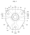
FIG. 1 is a front view of a reducing-agent injector gasket according to an embodiment of the present invention; -
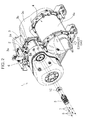
FIG. 2 is an exploded perspective view showing an exhaust-gas posttreatment apparatus including the reducing-agent injector gasket; -
FIG. 3 is a plan view of the exhaust-gas posttreatment apparatus; and -
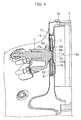
FIG. 4 is a sectional view showing the reducing-agent injector and the periphery of the reducing-agent injector in enlargement. - An embodiment of the present invention is explained below with reference to the drawings.
-
FIGS. 2 and3 show an exhaust-gas posttreatment apparatus 1 according to this embodiment. The exhaust-gas posttreatment apparatus 1 includes a diesel particulate filter (DPF)device 2, which is a filtering device for exhaust gas purification, a reducing-agent-water-solution mixing device (hereinafter referred to as "mixing device") 3, and a selective catalytic reduction (SCR)device 4. Themixing device 3 and theSCR device 4 constitute a urea SCR system. TheDPF device 2, themixing device 3, and theSCR device 4 are connected in this order from an upstream side of a flowing direction of an exhaust gas along an exhaust pipe in which the exhaust gas discharged from a not-shown diesel engine flows. The exhaust-gas posttreatment apparatus 1 is housed in an engine room of a construction machine such as a hydraulic shovel together with the diesel engine. - The
DPF device 2, which is located on the upstream-most side in the exhaust-gas posttreatment apparatus 1, includes acylindrical casing 2a and a not-shown DPF housed in thecasing 2a. The DPF plays a role of collecting particulate matters in an exhaust gas passing through the DPF. In thecasing 2a is disposed an oxidation catalyst located upstream of the DPF. The oxidation catalyst makes the particulate matters collected by the DPF self-burn with the exhaust gas having a high temperature to thus enable the DPF to be refreshed. - The
mixing device 3 is connected to an outlet of theDPF device 2 and adds a urea water solution, which is a reducing-agent water solution, to the flowing exhaust gas. Themixing device 3 includes a plurality of pipes configuring an exhaust pipe that allows the exhaust gas discharged from theDPF device 2 to flow through the pipes and a reducing-agent injector (hereinafter referred to as "injector") 5 capable of injecting urea water serving as a reducing agent into the exhaust pipe. The plurality of pipes include afirst elbow pipe 3a, astraight pipe 3b, and asecond elbow pipe 3c. Thestraight pipe 3b is connected to a downstream end of thefirst elbow pipe 3a and extends substantially in parallel to a flowing direction of the exhaust gas in theDPF device 2. Thesecond elbow pipe 3c is connected to a downstream end of thestraight pipe 3b. The exhaust pipe according to the present invention is, however, not limited to a specific form thereof. Theinjector 5 is attached to thefirst elbow pipe 3a and injects the urea water solution into the exhaust gas in thefirst elbow pipe 3a in a direction toward thestraight pipe 3b. The urea water solution comes into contact with the high-temperature exhaust gas to be thereby brought into thermal decomposition into ammonia and is supplied to thedownstream SCR device 4, together with the exhaust gas, as a reducing agent. - The
SCR device 4 includes acylindrical case 4a and a not-shown SCR catalyst housed in thecase 4a. The SCR catalyst plays a role of promoting a chemical reaction for purifying the exhaust gas, that is, an oxidation-reduction reaction of ammonia, which is a reducing agent generated by themixing device 3, and a nitrogen oxide in the exhaust gas. It is desirable to provide, for example, an ammonia reducing catalyst for promoting oxidation of the ammonia, which has not fully reacted with the nitrogen oxide, and detoxifying the ammonia, in thecase 4a. - The exhaust-gas posttreatment apparatus 1 further includes a reducing-agent-injector retention section (hereinafter simply referred to as "injector retention section") 6 and a reducing-agent injector gasket (hereinafter simply referred to as "gasket") 10.
- The
injector retention section 6 includes aretaining wall 6a provided in thefirst elbow pipe 3a as shown inFIGS. 2 and3 and fixed to thefirst elbow pipe 3a and a plurality of (e.g., three)retention bolts 6c that retain theinjector 5. - The
retaining wall 6a is formed of, for example, a circular plate member and surrounds a substantially circular injector opening 6b that pierces through a center part of theretaining wall 6a. Theinjector 5 includes aninjection nozzle 5a. Theinjector 5 is supported by the plurality ofretention bolts 6c of theinjector retention section 6 in a position which makes theinjection nozzle 5a coincident with the injector opening 6b. The injector opening 6b allows the reducing agent (the urea water) to be injected into the exhaust pipe from theinjector 5 through the injector opening 6b. - The plurality of
retention bolts 6c are fixed to theretaining wall 6a so as to project beyond theretaining wall 6a toward theinjector 5 around the injector opening 6b. The specific number of the plurality ofretention bolts 6c is set according to the specifications of theinjector 5. Theretaining wall 6a has an inner circumferential edge portion surrounding the injector opening 6b, the inner circumferential edge portion constituting a recessedportion 6d recessed toward theinjector 5 beyond the other portions. The recessedsection 6d has a shape with a diameter gradually increasing toward thestraight pipe 3b. - The
gasket 10 is disposed between theinjector retention section 6 and theinjector 5. Thegasket 10 is formed in, for example, a polygonal shape. Although thegasket 10 shown inFIG. 4 is formed in an octagonal shape, the shape of the gasket according to the present invention is not limited. The shape of the gasket may be another polygonal shape, a circular shape, or an elliptical shape. - As shown in
FIGS. 1 and4 in enlargement, thegasket 10 includes afirst plate 11, asecond plate 12, and aheat insulation member 14. Each of the first andsecond plates heat insulation member 14 is made of a material having thermal conductivity lower than the thermal conductivity of the first andsecond plates - The
first plate 11 is disposed in contact with the retainingwall 6a of theinjector retention section 6. Thefirst plate 11 is formed with afirst opening 11a corresponding to theinjector opening 6b of theretaining wall 6a and a plurality of (e.g., three) first bolt insert-throughholes 11b as many as theretention bolts 6c. Thefirst opening 11a allows the reducing agent to be injected from theinjector 5 through thefirst opening 11a. The first bolt insert-throughholes 11b allow therespective retention bolts 6c to be inserted through. - The
second plate 12 is disposed in contact with the distal end of theinjector 5. Thesecond plate 12 is formed with asecond opening 12a corresponding to theinjector opening 6b and a plurality of (e.g., three) second bolt insert-throughholes 12b as many as theretention bolts 6c. Thesecond opening 12a allows the reducing agent to be injected from theinjector 5 through thesecond opening 12a, specifically, allows theinjection nozzle 5a to be inserted into thesecond opening 12a. The second bolt insert-throughholes 12b allowrespective retention bolts 6c to be inserted through. - The first and
second plates protrusions 13 for joining theplates protrusions 13 includes a base portion projecting from each of outer circumferential sections of the first andsecond plates plate protrusions 13 opposed to each other also serve as a spacing keeping member for keeping a predetermined space between thefirst plate 11 and thesecond plate 12 by mutual contact of the distal end portions of the joiningprotrusions 13. - The
heat insulation member 14 is held between thefirst plate 11 and thesecond plate 12. Theheat insulation member 14 integrally includes amain body section 14A in the center and a plurality of bolt insert-throughsections 14B arranged around themain body section 14A. Themain body section 14A has an annular shape surrounding a heatinsulation member opening 14a. The heatinsulation member opening 14a coincides with thefirst opening 11a and thesecond opening 12a to thereby allow, in cooperation with the first andsecond openings injector 5 through theinjector opening 6b. The heatinsulation member opening 14a according to this embodiment allows, in cooperation with thesecond opening 12a, theinjection nozzle 5a of theinjector 5 to be inserted into theopenings sections 14B has an annular shape surrounding a heat-insulation-member-bolt insert-throughhole 14b. The heat-insulation-member-bolt insert-throughhole 14b coincides with the first bolt insert-thoughholes 11b and the second bolt insert-throughholes 12b to thereby allow theretention bolt 6c to be inserted through, in cooperation with the first and second bolt insert-throughholes - It is desirable that the
heat insulation member 14 is, for example, formed of a graphite sheet for high temperature and replaced every time a predetermined operation time elapses. - Although being annular, each of the
main body section 14A and the bolt insert-throughsections 14B may include alinear section 14c shown inFIG. 1 . The bolt insert-throughsections 14B are disposed so as to surround themain body section 14A and integrally joined to themain body section 14A. Themain body section 14A and the bolt insert-throughsections 14B may be joined such that respective parts of respective annular portions thereof mutually overlap as indicated by two bolt insert-throughsections 14B on the upper side inFIG. 1 or may be joined, for example, through alinear coupling section 14d as indicated by the bolt insert-throughsections 14B on the lower side inFIG. 1 . - The
heat insulation member 14 has a shape of allowing at least a part of theheat insulation member 14 to communicate with the outside air in a state in which theinjector 5 is retained by theinjector retention section 6, that is, a shape being opened to the outside of thegasket 10. In this embodiment, respective distal end portions (flat portions) of the joiningprotrusions 13 in the outer circumferential sections of the first andsecond plates 12 make contact with each other and joined by, for example, caulking, welding, or the like, while, in a region where the joiningprotrusions 13 are absent, the substantially entire outer circumferential section of theheat insulation member 14 is opened to the outside, thus allowed to be exposed to the outside air. - The
heat insulation member 14 does not have an external shape of occupying the entire space between thefirst plate 11 and thesecond plate 12 but has an external shape capable of forming aheat insulation space 15, in which theheat insulation member 14 is absent, between thefirst plate 11 and thesecond plate 12; theheat insulation member 14 in this embodiment has an external shape smaller than the external shape of the first andsecond plates heat insulation member 14 according to this embodiment, though including the annularmain body section 14A surrounding the heatinsulation member opening 14a that allows theinjection nozzle 5a to be inserted through and the plurality of annular bolt insert-throughsections 14B surrounding the heat-insulation-member-bolt insert-throughholes 14b that allow insertion-through of theretention bolts 6c, allows theheat insulation space 15 communicating with the outside air to be formed in a region where theheat insulation member 14 is absent, specifically, a region between the bolt insert-throughsections 14B adjacent to each other. - As shown in
FIG. 2 , the thus configuredgasket 10 can be surely fixed between the retainingwall 6a and theinjector 5 by inserting theretention bolts 6c through the first bolt insert-throughholes 11b, the second bolt insert-throughholes 12b, and the heat-insulation-member-bolt insert-throughholes 14b of thegasket 10, inserting theretention bolts 6c through the plurality of bolt insert-through holes provided in theinjector 5, and attaching and fastening, for example, washers 7 andnuts 8 to theretention bolts 6c. - As explained above, in this embodiment, the
gasket 10 interposed between theinjector 5 and theretaining wall 6a forms theheat insulation space 15, which suppresses heat transfer from exhaust gas to theinjector 5 to thereby enable the urea water solution in theinjector 5 to be prevented from deterioration due to high temperature. Moreover, theheat insulation space 15 communicating with the outside air is capable of suitable radiation, which allows a high heat insulation effect to be achieved, compared with a closed heat insulation space. - In particular, according to the
gasket 10 in this embodiment, theheat insulation member 14 interposed between the first andsecond plates injector 5. Also theheat insulation member 14, exposed to the outside air, is capable of suitable radiation, which allows a high heat insulation effect to be achieved, compared with a heat insulation member closed in a gasket. - The
heat insulation member 14, integrally including themain body section 14A surrounding the heatinsulation member opening 14a corresponding to theinjection nozzle 5a of theinjector 5 and the plurality of bolt insert-throughsections 14B through which theretention bolts 6c can be inserted, can have the small number of components and can be easily positioned. Specifically, only by respective insertions of theretention bolts 6c corresponding to the bolt insert-throughholes 14b through the respective bolt insert-throughholes 14b, the heatinsulation member opening 14a in the center and theinjector opening 6b can be automatically aligned with each other. This enables assembly efficiency to be markedly improved. - As explained above, the gasket (the reducing-agent injector gasket) 10 according to this embodiment effectively suppresses, with a simple configuration, heat transfer from the
first elbow pipe 3a and the like to theinjector 5. This makes it possible to provide the high-quality exhaust-gas posttreatment apparatus 1 capable of restraining urea water solution in theinjector 5 from deterioration. - The embodiment explained above is essentially a preferred illustration and is not meant to limit the present invention, applications of the present invention, and a range of use of the present invention.
- For example, the
heat insulation space 15 may be secured by a spacer made of a material having heat transfer properties instead of theheat insulation member 14 according to the embodiment. The spacer, if being made of a metal material such as a stainless steel material, can suppress heat transfer less than the embodiment but has an advantage of eliminating the necessity for exchange of the spacer and having high rigidity of the spacer is high. - The
main body section 14A and the plurality of bolt insert-throughsections 14B according to the embodiment may be configured as a plurality of heat insulation members independent of each other. Although increasing the number of heat insulation members, the configuration has an advantage of a larger total heat radiation area of the heat insulation members than that of a single heat insulation member. - As explained above, provided is a reducing-agent injector gasket capable of effectively suppressing heat transfer from an exhaust pipe to a reducing-agent injector and an exhaust-gas posttreatment apparatus including the same.
- Provided is a reducing-agent injector gasket to be interposed between a reducing-agent injector capable of injecting a reducing agent and an injector retention section provided to an exhaust pipe, the injector retention section including a retaining wall having an injector opening that allows the reducing agent to be injected from the reducing-agent injector into the exhaust pipe and a retention bolt projecting beyond the retaining wall to retain the reducing-agent injector. The reducing-agent injector gasket includes: a first plate to make contact with the retaining wall, the first plate having a first opening that allows the reducing agent to be injected, in cooperation with the injector opening of the retaining wall, and a first bolt insert-through hole that allows the retention bolt to be inserted through the first bolt insert-through hole; a second plate disposed in a position closer to the reducing-agent injector than the first plate, the second plate having a second opening that allows the reducing agent to be injected, in cooperation with the injector opening, and a second bolt insert-through hole that allows the retention bolt to be insert through the second bolt insert-through hole; and a spacing keeping member that keeps a spacing between the first plate and the second plate so as to form a heat insulation space between the first plate and the second plate. The heat insulation space has a shape that enables at least a part of the heat insulation space to communicate with the outside of the reducing-agent injector gasket between the first plate and the second plate in a state in which the reducing-agent injector is retained by the injector retention section via the reducing-agent injector gasket.
- The heat insulation space formed between the first and second plates in the reducing-agent injector gasket interposed between the reducing-agent injector and the retaining wall as explained above can effectively suppress heat transfer from the exhaust gas in the exhaust pipe to the reducing-agent injector, thereby preventing the reducing agent, for example, a urea water solution in the injector from deterioration due to a high temperature. Besides, the heat insulation space exposed to the outside air between the first plate and the second plate is capable of suitable radiation, which allows a high heat insulation effect to be achieved, compared with a closed heat insulation space.
- The spacing keeping member is suitably a heat insulation member interposed between the first plate and the second plate and having an external shape smaller than respective external shapes of the first plate and the second plate so as to form the heat insulation space around the heat insulation member. The heat insulation member can further improve the heat insulation effect in cooperation with the heat insulation space formed on the outer side of the heat insulation member.
- In this case, the heat insulation member is suitably a heat insulation member including an annular main body section surrounding a heat insulation member opening that allows the reducing agent to be injected from the reducing-agent injector, in cooperation with the first opening and the second opening, and an annular bolt insert-through section surrounding a heat-insulation-member-bolt insert-through hole that allows the retention bolt to be inserted through, in cooperation with the first bolt insert-through hole and the second bolt insert-through hole. The heat insulation member can be efficiently disposed in a region between the first and second plates while allowing the injection of the reducing agent and the insertion-through of the retention bolt. The "annular shape" only has to be a shape surrounding the heat insulation member opening and the heat-insulation-member-bolt insert-through hole, not required to have a circular outer circumference.
- It is more desirable that the main body section of the heat insulation member and the bolt insert-through section are integrally joined. This enables the number of components of the heat insulation member to be decreased and facilitates positioning the heat insulation member between the first plate and the second plate to allow assembly efficiency to be improved.
- The present invention also provides an exhaust-gas posttreatment apparatus for performing posttreatment of an exhaust gas flowing in an exhaust pipe. The apparatus includes a reducing-agent injector capable of injecting a reducing agent into the exhaust pipe, an injector retention section provided in the exhaust pipe and including a retaining wall having an injector opening that allows the reducing agent to be injected into the exhaust pipe from the reducing-agent injector and a retention bolt that projects beyond the retaining wall to retain the reducing-agent injector, and a reducing-agent injector gasket to be interposed between the reducing-agent injector and the injector retention section, the gasket having the above-described configuration.
- This application is based on
Japanese Patent application No. 2015-106647 filed in Japan Patent Office on May 26,2015 - Although the present invention has been fully described by way of example with reference to the accompanying drawings, it is to be understood that various changes and modifications will be apparent to those skilled in the art. Therefore, unless otherwise such changes and modifications depart from the scope of the present invention hereinafter defined, they should be construed as being included therein.
Provided is a gasket (10) effectively suppressing heat transfer from an exhaust pipe with an injector retention section to a reducing-agent injector. The gasket (10) includes a first plate (11) to contact a retaining wall of the injector retention section, the first plate (11) having a first opening (11a) allowing the reducing agent to be injected and a first bolt insert-throughhole 11b), a second plate (12) disposed closer to the reducing-agent injector than the first plate (11), the second plate (12) having a second opening (12a) allowing the reducing agent to be injected and a second bolt insert-through hole (12b), and a spacing keeping member (14) that retains a spacing between the first and second plates (11, 12) to form a heat insulation space (15) therebetween. The heat insulation space (15) has a shape allowing at least a part of the heat insulation space (15) to communicate with the outside of the gasket between the first and second plates (11, 12).
Claims (5)
- A reducing-agent injector gasket to be interposed between a reducing-agent injector capable of injecting a reducing agent and an injector retention section provided in an exhaust pipe, the injector retention section including a retaining wall having an injector opening that allows the reducing agent to be injected from the reducing-agent injector into the exhaust pipe and a retention bolt projecting beyond the retaining wall to retain the reducing-agent injector, the reducing-agent injector gasket comprising:a first plate to make contact with the retaining wall, the first plate having a first opening that allows the reducing agent to be injected, in cooperation with the injector opening of the retaining wall, and a first bolt insert-through hole that allows the retention bolt to be inserted through the first bolt insert-through hole;a second plate disposed in a position closer to the reducing-agent injector than the first plate, the second plate having a second opening that allows the reducing agent to be injected, in cooperation with the injector opening, and a second bolt insert-through hole that allows the retention bolt to be insert through the second bolt insert-through hole; anda spacing keeping member that keeps a spacing between the first plate and the second plate so as to form a heat insulation space between the first plate and the second plate, the heat insulation space having a shape that enables at least a part of the heat insulation space to communicate with the outside of the reducing-agent injector gasket between the first plate and the second plate in a state in which the reducing-agent injector is retained by the injector retention section via the reducing-agent injector gasket.
- The reducing-agent injector gasket according to claim 1, wherein the spacing keeping member includes a heat insulation member interposed between the first plate and the second plate, and the heat insulation space is formed around the heat insulation member.
- The reducing-agent injector gasket according to claim 2, wherein the heat insulation member includes an annular main body section surrounding a heat insulation member opening that allows the reducing agent to be injected from the reducing-agent injector, in cooperation with the first opening and the second opening and an annular bolt insert-through section surrounding a heat-insulation-member-bolt insert-through hole that allows the retention bolt to be inserted through, in cooperation with the first bolt insert-through hole and the second bolt insert-through hole.
- The reducing-agent injector gasket according to claim 3, wherein the main body section of the heat insulation member and the bolt insert-through section are integrally joined.
- An exhaust-gas posttreatment apparatus for performing posttreatment of an exhaust gas flowing in an exhaust pipe, the exhaust-gas posttreatment apparatus comprising:a reducing-agent injector capable of injecting a reducing agent into the exhaust pipe;an injector retention section provided in the exhaust pipe and including a retaining wall having an injector opening that allows the reducing agent to be injected into the exhaust pipe from the reducing-agent injector and a retention bolt that projects beyond the retaining wall to retain the reducing-agent injector; andthe reducing-agent injector gasket according to any one of claims 1 to 4 interposed between the reducing-agent injector and the injector retention section.
Applications Claiming Priority (1)
| Application Number | Priority Date | Filing Date | Title |
|---|---|---|---|
| JP2015106647A JP6345628B2 (en) | 2015-05-26 | 2015-05-26 | Gasket for reducing agent injector and exhaust gas aftertreatment device having the same |
Publications (2)
| Publication Number | Publication Date |
|---|---|
| EP3098407A1 true EP3098407A1 (en) | 2016-11-30 |
| EP3098407B1 EP3098407B1 (en) | 2018-01-03 |
Family
ID=55910826
Family Applications (1)
| Application Number | Title | Priority Date | Filing Date |
|---|---|---|---|
| EP16168050.9A Active EP3098407B1 (en) | 2015-05-26 | 2016-05-03 | Reducing-agent injector gasket and exhaust-gas posttreatment apparatus including same |
Country Status (4)
| Country | Link |
|---|---|
| US (1) | US10030563B2 (en) |
| EP (1) | EP3098407B1 (en) |
| JP (1) | JP6345628B2 (en) |
| CN (1) | CN106194343B (en) |
Cited By (2)
| Publication number | Priority date | Publication date | Assignee | Title |
|---|---|---|---|---|
| AT520706A1 (en) * | 2017-12-01 | 2019-06-15 | Avl List Gmbh | AFTERTREATMENT SYSTEM |
| IT202100006143A1 (en) * | 2021-03-15 | 2022-09-15 | Fpt Ind Spa | SYSTEM FOR INTERCONNECTION OF A UREA-BASED REDUCING AGENT INJECTOR TO A WASTE GAS POST-TREATMENT DEVICE |
Families Citing this family (5)
| Publication number | Priority date | Publication date | Assignee | Title |
|---|---|---|---|---|
| JP7086333B2 (en) * | 2018-01-30 | 2022-06-20 | 三菱ふそうトラック・バス株式会社 | Exhaust gas purification device |
| UA127461C2 (en) * | 2018-09-30 | 2023-08-30 | Вейчай Пауер Ко., Лтд. | Nozzle mounting assembly and post-treatment system |
| KR102617319B1 (en) * | 2019-01-21 | 2023-12-21 | 에이치디현대인프라코어 주식회사 | Adapter for injection module |
| BR112021017695A2 (en) * | 2019-03-14 | 2021-11-16 | Cummins Emission Solutions Inc | Systems and methods for mounting a doser on a component of an exhaust gas aftertreatment system |
| DE102019128193A1 (en) | 2019-10-18 | 2021-04-22 | Eberspächer Exhaust Technology GmbH | Mixer arrangement |
Citations (6)
| Publication number | Priority date | Publication date | Assignee | Title |
|---|---|---|---|---|
| JP2009138627A (en) * | 2007-12-06 | 2009-06-25 | Hino Motors Ltd | Urea water addition nozzle |
| JP4928304B2 (en) | 2007-02-23 | 2012-05-09 | 日野自動車株式会社 | Exhaust purification device |
| JP5349715B1 (en) | 2013-01-17 | 2013-11-20 | 株式会社小松製作所 | Reducing agent aqueous solution mixing device and exhaust gas aftertreatment device having the same |
| WO2013178321A1 (en) * | 2012-06-01 | 2013-12-05 | Daimler Ag | System for adding and processing reducing agent in a motor vehicle |
| US20140237998A1 (en) * | 2013-02-22 | 2014-08-28 | Caterpillar Inc. | Mounting assembly for reductant injector with thermal isolation and sealing gasket |
| JP2014163276A (en) * | 2013-02-25 | 2014-09-08 | Toyota Motor Corp | Addition valve supporting device |
Family Cites Families (6)
| Publication number | Priority date | Publication date | Assignee | Title |
|---|---|---|---|---|
| DE19806265C5 (en) * | 1998-02-16 | 2004-07-22 | Siemens Ag | dosing |
| US6279603B1 (en) * | 1998-10-01 | 2001-08-28 | Ambac International | Fluid-cooled injector |
| JP2005264756A (en) * | 2004-03-16 | 2005-09-29 | Toyota Industries Corp | Exhaust emission control device |
| US7467749B2 (en) * | 2004-04-26 | 2008-12-23 | Tenneco Automotive Operating Company Inc. | Methods and apparatus for injecting atomized reagent |
| JP2007321647A (en) * | 2006-05-31 | 2007-12-13 | Hitachi Ltd | Exhaust treatment equipment for engines |
| JP2008014213A (en) * | 2006-07-05 | 2008-01-24 | Hitachi Ltd | Exhaust treatment device |
-
2015
- 2015-05-26 JP JP2015106647A patent/JP6345628B2/en active Active
-
2016
- 2016-04-28 US US15/141,071 patent/US10030563B2/en active Active
- 2016-05-03 EP EP16168050.9A patent/EP3098407B1/en active Active
- 2016-05-06 CN CN201610298838.2A patent/CN106194343B/en active Active
Patent Citations (7)
| Publication number | Priority date | Publication date | Assignee | Title |
|---|---|---|---|---|
| JP4928304B2 (en) | 2007-02-23 | 2012-05-09 | 日野自動車株式会社 | Exhaust purification device |
| JP2009138627A (en) * | 2007-12-06 | 2009-06-25 | Hino Motors Ltd | Urea water addition nozzle |
| WO2013178321A1 (en) * | 2012-06-01 | 2013-12-05 | Daimler Ag | System for adding and processing reducing agent in a motor vehicle |
| JP5349715B1 (en) | 2013-01-17 | 2013-11-20 | 株式会社小松製作所 | Reducing agent aqueous solution mixing device and exhaust gas aftertreatment device having the same |
| US20140196442A1 (en) * | 2013-01-17 | 2014-07-17 | Komatsu Ltd. | Reductant aqueous solution mixing device and exhaust aftertreatment device provided with the same |
| US20140237998A1 (en) * | 2013-02-22 | 2014-08-28 | Caterpillar Inc. | Mounting assembly for reductant injector with thermal isolation and sealing gasket |
| JP2014163276A (en) * | 2013-02-25 | 2014-09-08 | Toyota Motor Corp | Addition valve supporting device |
Cited By (5)
| Publication number | Priority date | Publication date | Assignee | Title |
|---|---|---|---|---|
| AT520706A1 (en) * | 2017-12-01 | 2019-06-15 | Avl List Gmbh | AFTERTREATMENT SYSTEM |
| AT520706B1 (en) * | 2017-12-01 | 2020-10-15 | Avl List Gmbh | EXHAUST AFTER-TREATMENT SYSTEM |
| IT202100006143A1 (en) * | 2021-03-15 | 2022-09-15 | Fpt Ind Spa | SYSTEM FOR INTERCONNECTION OF A UREA-BASED REDUCING AGENT INJECTOR TO A WASTE GAS POST-TREATMENT DEVICE |
| WO2022195397A1 (en) * | 2021-03-15 | 2022-09-22 | Fpt Industrial S.P.A. | Interconnection system of a urea-based reducing agent injector to an after-treatment an exhaust gas device |
| US12286914B2 (en) | 2021-03-15 | 2025-04-29 | Fpt Industrial S.P.A | Interconnection system of a urea-based reducing agent injector to an after-treatment an exhaust gas device |
Also Published As
| Publication number | Publication date |
|---|---|
| EP3098407B1 (en) | 2018-01-03 |
| US20160348559A1 (en) | 2016-12-01 |
| CN106194343A (en) | 2016-12-07 |
| JP2016217337A (en) | 2016-12-22 |
| US10030563B2 (en) | 2018-07-24 |
| JP6345628B2 (en) | 2018-06-20 |
| CN106194343B (en) | 2020-03-06 |
Similar Documents
| Publication | Publication Date | Title |
|---|---|---|
| US10030563B2 (en) | Reducing-agent injector gasket and exhaust-gas posttreatment apparatus including same | |
| US8893481B2 (en) | Reductant aqueous solution mixing device and exhaust aftertreatment device provided with the same | |
| US8991160B2 (en) | Reductant aqueous solution mixing device and exhaust aftertreatment device provided with the same | |
| US9062589B2 (en) | Reductant aqueous solution mixing device and exhaust aftertreatment device provided with the same | |
| US8955312B2 (en) | Reductant aqueous solution mixing device and exhaust aftertreatment device provided with the same | |
| US8916101B2 (en) | Reducing agent aqueous solution mixing device and exhaust gas post-treatment device | |
| EP2984308B1 (en) | Mixer and emissions cleaning module | |
| CN103282616B (en) | Reducing agent aqueous solution mixing device and exhaust gas after-treatment device | |
| JP6208192B2 (en) | Exhaust gas treatment equipment | |
| CN103282615A (en) | Mixing device for reducing agent aqueous solution and exhaust gas post-processing device | |
| EP2573349B1 (en) | Exhaust pipe | |
| US9593613B2 (en) | Recessed exhaust reductant injector with cover plate | |
| CN111742122B (en) | Reducing agent injection device | |
| KR20150099893A (en) | Reducing agent dosing module and selective catalyst reduction system using the same | |
| KR102232267B1 (en) | An apparatus for reducing nitrogen oxide | |
| JP2018200040A (en) | Aftertreatment device of engine | |
| WO2019208449A1 (en) | Exhaust purification device | |
| JP2019132149A (en) | Exhaust emission control device | |
| JP2019218924A (en) | Exhaust emission control device |
Legal Events
| Date | Code | Title | Description |
|---|---|---|---|
| PUAI | Public reference made under article 153(3) epc to a published international application that has entered the european phase |
Free format text: ORIGINAL CODE: 0009012 |
|
| AK | Designated contracting states |
Kind code of ref document: A1 Designated state(s): AL AT BE BG CH CY CZ DE DK EE ES FI FR GB GR HR HU IE IS IT LI LT LU LV MC MK MT NL NO PL PT RO RS SE SI SK SM TR |
|
| AX | Request for extension of the european patent |
Extension state: BA ME |
|
| 17P | Request for examination filed |
Effective date: 20170427 |
|
| RBV | Designated contracting states (corrected) |
Designated state(s): AL AT BE BG CH CY CZ DE DK EE ES FI FR GB GR HR HU IE IS IT LI LT LU LV MC MK MT NL NO PL PT RO RS SE SI SK SM TR |
|
| RIC1 | Information provided on ipc code assigned before grant |
Ipc: F01N 3/28 20060101ALI20170621BHEP Ipc: F01N 3/035 20060101ALI20170621BHEP Ipc: F16J 15/00 20060101ALI20170621BHEP Ipc: F01N 3/20 20060101AFI20170621BHEP Ipc: F01N 13/18 20100101ALI20170621BHEP |
|
| GRAP | Despatch of communication of intention to grant a patent |
Free format text: ORIGINAL CODE: EPIDOSNIGR1 |
|
| INTG | Intention to grant announced |
Effective date: 20170728 |
|
| GRAS | Grant fee paid |
Free format text: ORIGINAL CODE: EPIDOSNIGR3 |
|
| GRAA | (expected) grant |
Free format text: ORIGINAL CODE: 0009210 |
|
| AK | Designated contracting states |
Kind code of ref document: B1 Designated state(s): AL AT BE BG CH CY CZ DE DK EE ES FI FR GB GR HR HU IE IS IT LI LT LU LV MC MK MT NL NO PL PT RO RS SE SI SK SM TR |
|
| REG | Reference to a national code |
Ref country code: GB Ref legal event code: FG4D |
|
| REG | Reference to a national code |
Ref country code: CH Ref legal event code: EP Ref country code: AT Ref legal event code: REF Ref document number: 960484 Country of ref document: AT Kind code of ref document: T Effective date: 20180115 |
|
| REG | Reference to a national code |
Ref country code: IE Ref legal event code: FG4D |
|
| REG | Reference to a national code |
Ref country code: DE Ref legal event code: R096 Ref document number: 602016001269 Country of ref document: DE |
|
| REG | Reference to a national code |
Ref country code: NL Ref legal event code: MP Effective date: 20180103 |
|
| REG | Reference to a national code |
Ref country code: FR Ref legal event code: PLFP Year of fee payment: 3 |
|
| REG | Reference to a national code |
Ref country code: LT Ref legal event code: MG4D |
|
| REG | Reference to a national code |
Ref country code: AT Ref legal event code: MK05 Ref document number: 960484 Country of ref document: AT Kind code of ref document: T Effective date: 20180103 |
|
| PG25 | Lapsed in a contracting state [announced via postgrant information from national office to epo] |
Ref country code: NL Free format text: LAPSE BECAUSE OF FAILURE TO SUBMIT A TRANSLATION OF THE DESCRIPTION OR TO PAY THE FEE WITHIN THE PRESCRIBED TIME-LIMIT Effective date: 20180103 |
|
| PG25 | Lapsed in a contracting state [announced via postgrant information from national office to epo] |
Ref country code: NO Free format text: LAPSE BECAUSE OF FAILURE TO SUBMIT A TRANSLATION OF THE DESCRIPTION OR TO PAY THE FEE WITHIN THE PRESCRIBED TIME-LIMIT Effective date: 20180403 Ref country code: ES Free format text: LAPSE BECAUSE OF FAILURE TO SUBMIT A TRANSLATION OF THE DESCRIPTION OR TO PAY THE FEE WITHIN THE PRESCRIBED TIME-LIMIT Effective date: 20180103 Ref country code: LT Free format text: LAPSE BECAUSE OF FAILURE TO SUBMIT A TRANSLATION OF THE DESCRIPTION OR TO PAY THE FEE WITHIN THE PRESCRIBED TIME-LIMIT Effective date: 20180103 Ref country code: HR Free format text: LAPSE BECAUSE OF FAILURE TO SUBMIT A TRANSLATION OF THE DESCRIPTION OR TO PAY THE FEE WITHIN THE PRESCRIBED TIME-LIMIT Effective date: 20180103 Ref country code: CY Free format text: LAPSE BECAUSE OF FAILURE TO SUBMIT A TRANSLATION OF THE DESCRIPTION OR TO PAY THE FEE WITHIN THE PRESCRIBED TIME-LIMIT Effective date: 20180103 Ref country code: FI Free format text: LAPSE BECAUSE OF FAILURE TO SUBMIT A TRANSLATION OF THE DESCRIPTION OR TO PAY THE FEE WITHIN THE PRESCRIBED TIME-LIMIT Effective date: 20180103 |
|
| PG25 | Lapsed in a contracting state [announced via postgrant information from national office to epo] |
Ref country code: GR Free format text: LAPSE BECAUSE OF FAILURE TO SUBMIT A TRANSLATION OF THE DESCRIPTION OR TO PAY THE FEE WITHIN THE PRESCRIBED TIME-LIMIT Effective date: 20180404 Ref country code: IS Free format text: LAPSE BECAUSE OF FAILURE TO SUBMIT A TRANSLATION OF THE DESCRIPTION OR TO PAY THE FEE WITHIN THE PRESCRIBED TIME-LIMIT Effective date: 20180503 Ref country code: PL Free format text: LAPSE BECAUSE OF FAILURE TO SUBMIT A TRANSLATION OF THE DESCRIPTION OR TO PAY THE FEE WITHIN THE PRESCRIBED TIME-LIMIT Effective date: 20180103 Ref country code: LV Free format text: LAPSE BECAUSE OF FAILURE TO SUBMIT A TRANSLATION OF THE DESCRIPTION OR TO PAY THE FEE WITHIN THE PRESCRIBED TIME-LIMIT Effective date: 20180103 Ref country code: AT Free format text: LAPSE BECAUSE OF FAILURE TO SUBMIT A TRANSLATION OF THE DESCRIPTION OR TO PAY THE FEE WITHIN THE PRESCRIBED TIME-LIMIT Effective date: 20180103 Ref country code: SE Free format text: LAPSE BECAUSE OF FAILURE TO SUBMIT A TRANSLATION OF THE DESCRIPTION OR TO PAY THE FEE WITHIN THE PRESCRIBED TIME-LIMIT Effective date: 20180103 Ref country code: RS Free format text: LAPSE BECAUSE OF FAILURE TO SUBMIT A TRANSLATION OF THE DESCRIPTION OR TO PAY THE FEE WITHIN THE PRESCRIBED TIME-LIMIT Effective date: 20180103 Ref country code: BG Free format text: LAPSE BECAUSE OF FAILURE TO SUBMIT A TRANSLATION OF THE DESCRIPTION OR TO PAY THE FEE WITHIN THE PRESCRIBED TIME-LIMIT Effective date: 20180403 |
|
| REG | Reference to a national code |
Ref country code: DE Ref legal event code: R097 Ref document number: 602016001269 Country of ref document: DE |
|
| PG25 | Lapsed in a contracting state [announced via postgrant information from national office to epo] |
Ref country code: EE Free format text: LAPSE BECAUSE OF FAILURE TO SUBMIT A TRANSLATION OF THE DESCRIPTION OR TO PAY THE FEE WITHIN THE PRESCRIBED TIME-LIMIT Effective date: 20180103 Ref country code: AL Free format text: LAPSE BECAUSE OF FAILURE TO SUBMIT A TRANSLATION OF THE DESCRIPTION OR TO PAY THE FEE WITHIN THE PRESCRIBED TIME-LIMIT Effective date: 20180103 Ref country code: RO Free format text: LAPSE BECAUSE OF FAILURE TO SUBMIT A TRANSLATION OF THE DESCRIPTION OR TO PAY THE FEE WITHIN THE PRESCRIBED TIME-LIMIT Effective date: 20180103 |
|
| PLBE | No opposition filed within time limit |
Free format text: ORIGINAL CODE: 0009261 |
|
| STAA | Information on the status of an ep patent application or granted ep patent |
Free format text: STATUS: NO OPPOSITION FILED WITHIN TIME LIMIT |
|
| PG25 | Lapsed in a contracting state [announced via postgrant information from national office to epo] |
Ref country code: CZ Free format text: LAPSE BECAUSE OF FAILURE TO SUBMIT A TRANSLATION OF THE DESCRIPTION OR TO PAY THE FEE WITHIN THE PRESCRIBED TIME-LIMIT Effective date: 20180103 Ref country code: SM Free format text: LAPSE BECAUSE OF FAILURE TO SUBMIT A TRANSLATION OF THE DESCRIPTION OR TO PAY THE FEE WITHIN THE PRESCRIBED TIME-LIMIT Effective date: 20180103 Ref country code: DK Free format text: LAPSE BECAUSE OF FAILURE TO SUBMIT A TRANSLATION OF THE DESCRIPTION OR TO PAY THE FEE WITHIN THE PRESCRIBED TIME-LIMIT Effective date: 20180103 Ref country code: SK Free format text: LAPSE BECAUSE OF FAILURE TO SUBMIT A TRANSLATION OF THE DESCRIPTION OR TO PAY THE FEE WITHIN THE PRESCRIBED TIME-LIMIT Effective date: 20180103 |
|
| 26N | No opposition filed |
Effective date: 20181005 |
|
| REG | Reference to a national code |
Ref country code: BE Ref legal event code: MM Effective date: 20180531 |
|
| PG25 | Lapsed in a contracting state [announced via postgrant information from national office to epo] |
Ref country code: MC Free format text: LAPSE BECAUSE OF FAILURE TO SUBMIT A TRANSLATION OF THE DESCRIPTION OR TO PAY THE FEE WITHIN THE PRESCRIBED TIME-LIMIT Effective date: 20180103 |
|
| REG | Reference to a national code |
Ref country code: IE Ref legal event code: MM4A |
|
| PG25 | Lapsed in a contracting state [announced via postgrant information from national office to epo] |
Ref country code: SI Free format text: LAPSE BECAUSE OF FAILURE TO SUBMIT A TRANSLATION OF THE DESCRIPTION OR TO PAY THE FEE WITHIN THE PRESCRIBED TIME-LIMIT Effective date: 20180103 |
|
| PG25 | Lapsed in a contracting state [announced via postgrant information from national office to epo] |
Ref country code: LU Free format text: LAPSE BECAUSE OF NON-PAYMENT OF DUE FEES Effective date: 20180503 |
|
| PG25 | Lapsed in a contracting state [announced via postgrant information from national office to epo] |
Ref country code: IE Free format text: LAPSE BECAUSE OF NON-PAYMENT OF DUE FEES Effective date: 20180503 |
|
| PG25 | Lapsed in a contracting state [announced via postgrant information from national office to epo] |
Ref country code: BE Free format text: LAPSE BECAUSE OF NON-PAYMENT OF DUE FEES Effective date: 20180531 |
|
| REG | Reference to a national code |
Ref country code: CH Ref legal event code: PL |
|
| PG25 | Lapsed in a contracting state [announced via postgrant information from national office to epo] |
Ref country code: CH Free format text: LAPSE BECAUSE OF NON-PAYMENT OF DUE FEES Effective date: 20190531 Ref country code: MT Free format text: LAPSE BECAUSE OF NON-PAYMENT OF DUE FEES Effective date: 20180503 Ref country code: LI Free format text: LAPSE BECAUSE OF NON-PAYMENT OF DUE FEES Effective date: 20190531 |
|
| PG25 | Lapsed in a contracting state [announced via postgrant information from national office to epo] |
Ref country code: TR Free format text: LAPSE BECAUSE OF FAILURE TO SUBMIT A TRANSLATION OF THE DESCRIPTION OR TO PAY THE FEE WITHIN THE PRESCRIBED TIME-LIMIT Effective date: 20180103 |
|
| PG25 | Lapsed in a contracting state [announced via postgrant information from national office to epo] |
Ref country code: PT Free format text: LAPSE BECAUSE OF FAILURE TO SUBMIT A TRANSLATION OF THE DESCRIPTION OR TO PAY THE FEE WITHIN THE PRESCRIBED TIME-LIMIT Effective date: 20180103 |
|
| PG25 | Lapsed in a contracting state [announced via postgrant information from national office to epo] |
Ref country code: MK Free format text: LAPSE BECAUSE OF NON-PAYMENT OF DUE FEES Effective date: 20180103 Ref country code: HU Free format text: LAPSE BECAUSE OF FAILURE TO SUBMIT A TRANSLATION OF THE DESCRIPTION OR TO PAY THE FEE WITHIN THE PRESCRIBED TIME-LIMIT; INVALID AB INITIO Effective date: 20160503 |
|
| REG | Reference to a national code |
Ref country code: FR Ref legal event code: PLFP Year of fee payment: 8 |
|
| PGFP | Annual fee paid to national office [announced via postgrant information from national office to epo] |
Ref country code: IT Payment date: 20240411 Year of fee payment: 9 |
|
| PGFP | Annual fee paid to national office [announced via postgrant information from national office to epo] |
Ref country code: GB Payment date: 20250327 Year of fee payment: 10 |
|
| PGFP | Annual fee paid to national office [announced via postgrant information from national office to epo] |
Ref country code: DE Payment date: 20250402 Year of fee payment: 10 |
|
| PGFP | Annual fee paid to national office [announced via postgrant information from national office to epo] |
Ref country code: FR Payment date: 20250401 Year of fee payment: 10 |
|
| PG25 | Lapsed in a contracting state [announced via postgrant information from national office to epo] |
Ref country code: IT Free format text: LAPSE BECAUSE OF NON-PAYMENT OF DUE FEES Effective date: 20250503 |