EP3098192A1 - An arrangement and a method for installing or uninstalling elevator ropes - Google Patents
An arrangement and a method for installing or uninstalling elevator ropes Download PDFInfo
- Publication number
- EP3098192A1 EP3098192A1 EP15169081.5A EP15169081A EP3098192A1 EP 3098192 A1 EP3098192 A1 EP 3098192A1 EP 15169081 A EP15169081 A EP 15169081A EP 3098192 A1 EP3098192 A1 EP 3098192A1
- Authority
- EP
- European Patent Office
- Prior art keywords
- rope
- rollers
- electric motor
- elevator
- reel
- Prior art date
- Legal status (The legal status is an assumption and is not a legal conclusion. Google has not performed a legal analysis and makes no representation as to the accuracy of the status listed.)
- Granted
Links
- 238000000034 method Methods 0.000 title claims description 25
- 229910000831 Steel Inorganic materials 0.000 claims description 6
- 239000010959 steel Substances 0.000 claims description 6
- 238000005096 rolling process Methods 0.000 description 6
- 230000032258 transport Effects 0.000 description 6
- 239000011248 coating agent Substances 0.000 description 5
- 238000000576 coating method Methods 0.000 description 5
- 239000000725 suspension Substances 0.000 description 5
- 238000009434 installation Methods 0.000 description 3
- 239000000463 material Substances 0.000 description 2
- 230000001105 regulatory effect Effects 0.000 description 2
- 239000007787 solid Substances 0.000 description 2
- 239000002131 composite material Substances 0.000 description 1
- 230000001276 controlling effect Effects 0.000 description 1
- 239000011159 matrix material Substances 0.000 description 1
- 230000004048 modification Effects 0.000 description 1
- 238000012986 modification Methods 0.000 description 1
- 229920000642 polymer Polymers 0.000 description 1
- 239000012783 reinforcing fiber Substances 0.000 description 1
Images


Classifications
-
- B—PERFORMING OPERATIONS; TRANSPORTING
- B66—HOISTING; LIFTING; HAULING
- B66B—ELEVATORS; ESCALATORS OR MOVING WALKWAYS
- B66B19/00—Mining-hoist operation
- B66B19/02—Installing or exchanging ropes or cables
Definitions
- the rope reeling process corresponds as such to the rope reeling process described in figure 3 .
- the rope reeling unit 100 controls now directly the rotation of the rope reel 200 via the shaft 140 and thereby indirectly the reeling of the rope R.
- the rope reeling unit 100 controls in figure 3 directly the reeling of the rope R and indirectly the rotation of the rope reel 200.
- the elevator could have a hoisting height of over 30 meters, preferably 30-80 meters, most preferably 40-80 meters.
Landscapes
- Lift-Guide Devices, And Elevator Ropes And Cables (AREA)
Abstract
Description
- The invention relates to an arrangement and a method for installing or uninstalling elevator ropes.
- An elevator comprises an elevator car, lifting machinery, ropes, and a counter weight. The elevator car is supported on a transport frame being formed by a sling or a car frame. The transport frame surrounds the elevator car. The lifting machinery comprises a sheave, a machinery brake and an electric motor for rotating the sheave. The lifting machinery moves the car upwards and downwards in a vertically extending elevator shaft. The transport frame and thereby also the elevator car are carried by the ropes, which connect the elevator car to the counter weight. The transport frame of the elevator car is further supported with gliding means at guide rails extending in the vertical direction in the elevator shaft. The gliding means can comprise rolls rolling on the guide rails or gliding shoes gliding on the guide rails when the elevator car is mowing upwards and downwards in the elevator shaft. The guide rails are supported with support means on the side wall structures of the elevator shaft. The gliding means engaging with the guide rails keep the elevator car in position in the horizontal plane when the elevator car moves upwards and downwards in the elevator shaft. The counter weight is supported in a corresponding way on guide rails supported with support means on the wall structure of the elevator shaft. The elevator car transports people and/or goods between the landings in the building. The elevator shaft can be formed so that the wall structure is formed of solid walls or so that the wall structure is formed of an open steel structure.
- When an elevator installation in a high rise building is performed, the roping process requires a lot of manual work. The ropes are in a new elevator installation positioned on rope reels and are then reeled from the rope reels to the shaft. The old ropes are in a replacement of ropes reeled on empty reels. The rope reels are driven manually i.e. a fitter rotates and controls the rope reels.
- When installing new ropes, one to ten ropes can be lifted simultaneously depending on the weight of the ropes. One fitter can control the rolling of maximum four rope reels. The fitter controls and keeps the reel rolling speeds in each rope reel on such a level that the ropes are kept on a desired tightness on their way to the elevator shaft. The idea is to avoid unnecessary slack in the ropes when they pass to the elevator shaft.
- When uninstalling old ropes, one to ten ropes can be removed simultaneously depending on the weight of the ropes. The fitter is rolling the reel manually and one fitter can roll one to two reels. The fitter rolls the reels so that the old ropes are removed from the shaft and reeled on the empty reel that he is rolling. The number of fitters that are available limits the number of ropes that can be changed on one run. It is possible to roll several ropes on one reel, but the ropes have to be cut when the reel gets full and then one has to continue on the next reel.
- An object of the present invention is to save manual work during the installation and/or replacement of ropes in an elevator.
- The arrangement for installing or uninstalling elevator ropes is defined in
claim 1. - The arrangement for installing or uninstalling elevator ropes comprising at least one rope reel and a rope reel unit comprising a frame and at least one rotating rope feed member. The at least one rotating rope feed member is driven by an electric drive unit comprising an electric motor and a gear, the electric motor being driven by a frequency converter by which the torque of the electric motor is adjustable continuously, whereby the feeding of at least one rope from the at least one rope reel is controlled directly or indirectly by the at least one rope feed member.
- The method for installing or uninstalling elevator ropes is defined in
claim 10. - The method for installing or uninstalling elevator ropes comprises the steps of:
- feeding at least one rope from at least one rope reel over a traction sheave to an elevator shaft or feeding the at least one rope in the opposite direction,
- controlling the feeding of the at least one rope directly or indirectly with a rope reel unit comprising a frame and at least one rotating rope feed member, whereby the at least one rotating rope feed member is driven by an electric drive unit comprising an electric motor and a gear, the electric motor being driven by a frequency converter by which the torque of the electric motor is adjustable continuously.
- The invention makes it possible to control the rope feeding effectively in an elevator rope reeling process.
- The invention makes it also possible to control the rope reeling from several rope reels with one rope reeling unit.
- The invention will in the following be described in greater detail by means of preferred embodiments with reference to the attached drawings, in which:
-
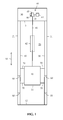
Figure 1 shows a vertical cross section of an elevator, -
Figure 2 shows a horizontal cross section of the elevator, -
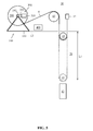
Figure 3 shows an arrangement for installing or uninstalling elevator ropes according to a first embodiment of the invention, -
Figure 4 shows an arrangement for installing or uninstalling elevator ropes according to a second embodiment of the invention, -
Figure 5 shows an arrangement for installing or uninstalling elevator ropes according to a third embodiment of the invention. -
Figure 1 shows a vertical cross section andfigure 2 shows a horizontal cross section of an elevator. - The elevator comprises a
car 10, anelevator shaft 20, amachine room 30,lifting machinery 40,ropes 41, and acounterweight 42. Thecar 10 is supported on a sling 11 or transport frame surrounding thecar 10. Thelifting machinery 40 comprises atraction sheave 43, an electric motor 44 for rotating thetraction sheave 43 via ashaft 45, and amachinery brake 46 for braking the rotation of thetraction sheave 45. Thelifting machinery 40 moves thecar 10 in a first direction S1 upwards and downwards in a vertically extendingelevator shaft 20. Thesling 11 and thereby also theelevator car 10 are carried by theropes 41, which connect theelevator car 10 to thecounter weight 42. Thesling 11 and thereby also theelevator car 10 is further supported withgliding means 70 atguide rails 50 extending in the vertical direction in theelevator shaft 20. There are twoguide rails elevator car 10. The elevatorcar guide rails opposite side walls shaft 20. The gliding means 70 can comprise rolls rolling on theguide rails 50 or gliding shoes gliding on theguide rails 50 when theelevator car 10 is mowing upwards and downwards in theelevator shaft 20. There are further twoguide rails counter weight 42 positioned on theback wall 21 B of theshaft 20. Thecounterweight 42 is supported with corresponding gliding means 70 on the counterweight guide rails - The
guide rails 50 are fastened with support means 60 at thewalls shaft 20. The figure shows only two support means 60, but there are several support means 60 along the height of eachguide rail 50. The cross section of theguide rails 50 may have the form of a letter T. The vertical branch of theguide rail element 50 forms three gliding surfaces for the gliding means 70 comprising rolls or gliding shoes. There are thus two opposite side gliding surfaces and one front gliding surface in theguide rail 50. The cross-section of the gliding means 70 has the form of a letter U so that the inner surface of the gliding means 70 sets against the three gliding surfaces of theguide rail 50. The gliding means 70 are attached to thesling 11 and/or to thecounter weight 42. - The
elevator shaft 20 can be formed so that thewalls walls - The figures show a first direction S1, which is a vertical direction in the
elevator shaft 20, a second direction S2, which is the direction between the guide rails (DBG) and a third direction S3, which is the direction from theback wall 21 B to the front wall 21A in the shaft 20 (BTF). The second direction S2 is perpendicular to the third direction S3. -
Figure 3 shows an arrangement for installing or installing elevator ropes according to a first embodiment of the invention. The arrangement comprises arope reel 200 and arope reeling unit 100. Therope reel 200 is supported through twosupport rollers support frame 510. Thesupport rollers support frame 510. Bothsupport rollers rope reeling unit 100 comprises aframe 110, two rotatingrope feed members electric drive unit 300. Therope reel 200 and therope reeling unit 100 are at a distance from each other. The rope R runs from therope reel 200 over thetraction sheave 43 of the elevator machinery to a gap G between the tworollers elevator shaft 20. The tworollers weight suspension sheave 15 and further upwards to themachine room 30 where the first end of the rope R is fixed at afixing point 47. At least one 120 of the tworollers electric drive unit 300 comprising anelectric motor 310 and agear 320. It might, however, be advantageous to drive bothrollers electric drive unit 300. Theelectric motor 310 is driven by afrequency converter 400 by which the torque or the rotation speed of theelectric motor 310 can be adjusted continuously. Therope reel 200, thesupport rollers support frame 510, thetraction sheave 43, therollers electric drive 300 and thefrequency converter 400 are positioned in themachine room 30 above theelevator shaft 20. The rotation speed of therollers electric motor 310 with thefrequency converter 400. The length L1 of the rope loop in theelevator shaft 20 can be increased in a controlled way by feeding rope R through therollers elevator shaft 20. The counterweight suspension sheave 15 positioned within the rope loop will be lowered in theelevator shaft 20 as the length L1 of the rope loop increases. The counterweight suspension sheave 15 is lowered to the height of thecounter weight 42 positioned at the bottom 12 of theelevator shaft 20. The counterweight suspension sheave 15 can then be attached to the fixing means positioned at the upper end of thecounter weight 42. The second opposite end of the rope R will after thetraction sheave 43 run around the car suspension sheave or sheaves after which said second end of the rope R is fixed at a fixing point in themachine room 30. The elevator roping system will thus be a 2:1 elevator roping system. - Several
adjacent rope reels 200 can be situated on thesupport frame 510. The ropes R of all therope reels 200 can be fed simultaneously through therope reeling unit 100. Only onerope reeling unit 100 is thus needed to control the reeling of several ropes R. - The arrangement shown in
figure 3 can advantageously be used in reeling belt shaped ropes having a greater width compared to the thickness of the rope. The width to thickness ratio in these belt shaped ropes is typically at least 2. Such ropes comprise a coating and a plurality of adjacent parallel load bearing members embedded in the coating and running along the longitudinal direction of the rope. The load bearing members bear the load exerted on the rope R in the longitudinal direction of the rope R. The coating forms the outer surface of the rope R and extends between adjacent load bearing members thereby isolating them from each other. The load bearing members are preferably made of composite material comprising reinforcing fibers in a polymer matrix. The coating is preferably of a material having a fairly high friction so that therollers rollers figure 3 in order to direct the rope R downwards after thetraction sheave 43. -
Figure 4 shows an arrangement for installing or uninstalling elevator ropes according to a second embodiment of the invention. Therope reeling unit 100 is in this embodiment moved from a position above the opening after thetraction sheave 43 to a position under therope reel 200. Therope reeling unit 100 comprises in the same way as in the embodiment shown infigure 3 aframe 110 provided with tworope feed members rope feed members frame 110. At least one 130 of therollers electric drive unit 300 comprising andelectric motor 310 and agear 320. It might be advantageous to have bothrollers electric drive unit 300. Theelectric motor 310 is driven by afrequency converter 400 by which the torque or the rotation speed of theelectric motor 310 can be adjusted continuously. The load of theelectric motor 310 determines the magnitude of the torque in rotation speed control. The load of theelectric motor 310 determines the rotation speed of the electric motor in torque control. Arope reel 200 is supported on therollers rope reeling unit 100. The outer circumference of therope reel 200 rests on therollers rope reeling unit 100 measured in the axial direction of therollers several rope reels 200 can be positioned adjacent to each other onrollers rope reeling unit 100. This means thatseveral rope reels 200 can be controlled with onerope reeling unit 100. The length of therope reeling unit 100 measured in the axial direction of therollers - The rope reeling process corresponds as such to the rope reeling process described in
figure 3 . Therope reeling unit 100 controls now directly the rotation of therope reel 200 and thereby indirectly the reeling of the rope R. Therope reeling unit 100 controls infigure 3 directly the reeling of the rope R and indirectly the rotation of therope reel 200. - The arrangement shown in
figure 4 can advantageously be used in reeling twisted steel ropes having a more or less round cross section. - Guide rollers could be used in guiding the rope R after the
traction sheave 43 through the opening in the floor of themachine room 30 if needed. These guide rollers would not be driven. -
Figure 5 shows an arrangement for installing or uninstalling elevator ropes according to a third embodiment of the invention. This elevatorrope reeling unit 100 is a modification of therope reeling unit 100 shown infigure 4 . Therope reeling unit 100 comprises aframe 110 that supports a rotatingrope feed member 140. The rotatingrope feed member 140 is formed of a shaft passing through a hole in the middle of therope reel 200. Both ends of theshaft 140 are rotatably supported on theframe 110. Theshaft 140 is driven by anelectric drive unit 300 comprising anelectric motor 310 and agear 320. Theelectric motor 310 is driven by afrequency converter 400 by which the torque or the rotation speed of theelectric motor 310 can be adjusted continuously. Arope reel 200 is supported on theshaft 140 in therope reeling unit 100 so that therope reel 200 rotates with theshaft 140. The length of therope reeling unit 100 measured in the axial direction of theshaft 140 can be such thatseveral rope reels 200 can be positioned adjacent to each other on theshaft 140 in onerope reeling unit 100. This means thatseveral rope reels 200 can be controlled with onerope reeling unit 100. The length of therope reeling unit 100 measured in the axial direction of theshaft 140 can also be made adjustable. - The rope reeling process corresponds as such to the rope reeling process described in
figure 3 . Therope reeling unit 100 controls now directly the rotation of therope reel 200 via theshaft 140 and thereby indirectly the reeling of the rope R. Therope reeling unit 100 controls infigure 3 directly the reeling of the rope R and indirectly the rotation of therope reel 200. - The rope reeling unit shown in
figure 5 can advantageously be used in reeling twisted steel ropes having a more or less round cross section. - The arrangement and the method according to the invention can be used when new ropes are to be installed into the elevator shaft and when old ropes are to be replaced by new ropes in the elevator shaft. When uninstalling i.e. reeling old ropes onto the
rope reel 200 theelectric drive unit 300 rotates therope reel 200 and keeps the torque acting on therope reel 200 constant. The rotation speed of therope reel 200 is not a good target for thefrequency converter 400 in this case. This is due to the fact that the radius of the rope layer on therope reel 200 changes when the amount of rope changes on therope reel 200. - The arrangement and the method can be used in a 2:1 elevator roping system or in a higher order elevator roping system.
- The elevator could have a hoisting height of over 30 meters, preferably 30-80 meters, most preferably 40-80 meters.
- The elevator could on the other hand have a hoisting height of over 75 meters, preferably over 100 meters, more preferably over 150 meters, most preferably over 250 meters. In elevators with a great hoisting height long ropes have to be used, whereby the weight of the ropes becomes considerable. This makes the use of the invention even more advantageous as the reeling of the ropes can easily be controlled in reliable manner by only one or maybe two fitters.
- The use of the invention is naturally not limited to the type of elevator disclosed in the figures. The invention can be used in any type of elevator e.g. also in elevators lacking a machine room and/or a counterweight. The counter weight could be positioned on the back wall or on at either side wall of the elevator shaft or on both side walls of the elevator shaft. The lifting machinery could be positioned at the top of the elevator shaft or at the bottom of the elevator shaft or within the elevator shaft at either side wall of the elevator shaft.
- It will be obvious to a person skilled in the art that, as the technology advances, the inventive concept can be implemented in various ways. The invention and its embodiments are not limited to the examples described above but may vary within the scope of the claims.
Claims (20)
- An arrangement for installing or uninstalling elevator ropes comprising at least one rope reel (200) and a rope reel unit (100) comprising a frame (110) and at least one rotating rope feed member (120, 130, 140), characterised in that the at least one rotating rope feed member (120, 130, 140) is driven by an electric drive unit (300) comprising an electric motor (310) and a gear (320), the electric motor (310) being driven by a frequency converter (400) by which the torque of the electric motor (310) is adjustable continuously, whereby the feeding of at least one rope (R) from the at least one rope reel (200) is controlled directly or indirectly by the at least one rope feed member (120, 130, 140).
- An arrangement according to claim 1, characterized in that the arrangement comprises several rope reels (200), whereby the rope reeling of the ropes from all the rope reels (200) is controlled by the same rope reel unit 100.
- An arrangement according to claim 1 or 2, characterized in that the at least one rope feed member (120, 130, 140) is formed by two rollers (120, 130) forming a gap (G) between them, said rollers (120, 130) being rotatably supported on the frame (110) and at least one of the rollers (120) being driven by the electric motor (310), whereby the at least one rope (R) from the at least one rope reel (200) passes through the gap (G), the at least one rope (R) being slightly pressed between the two rollers (120, 130) enabling feeding of the at least one rope (R) by rotating the rollers (120, 130).
- An arrangement according to claim 3, characterized in that the at least one rope (R) to be installed is a belt shaped rope having a greater width compared to the thickness of the rope, the width to thickness ratio being advantageously at least 2.
- An arrangement according to claim 1 or 2, characterized in that the at least one support member (120, 130, 140) is formed by two rollers (120, 130) rotatably supported on the frame (110) and positioned at a distance from each other, the rope reel (200) being supported on the rollers (120, 130), whereby at least one of the rollers (130) is driven by the electric motor (310).
- An arrangement according to claim 1 or 2, characterized in that the at least one support member (120, 130, 140) is formed by a shaft (140) rotatably supporting the rope reel (200), whereby the shaft (140) is driven by the electric motor (310).
- An arrangement according to claim 5 or 6, characterized in that the rope (R) to be installed is a twisted steel rope.
- An arrangement according to any one of claims 1 to 7, characterized in that the arrangement is used in a 2:1 elevator roping system or in a higher order elevator roping system.
- An arrangement according to any one of claims 1 to 8, characterized in that the arrangement is used in an elevator shaft (20) in a high rise building having a hoisting height of over 75 meters, preferably over 100 meters, more preferably over 150 meters, most preferably over 250 meters.
- A method for installing or uninstalling elevator ropes comprising the step of feeding at least one rope (R) from at least one rope reel (200) over a traction sheave (43) to an elevator shaft (20) or feeding the at least one rope (R) in the opposite direction,
characterized by the further step of:controlling the feeding of the at least one rope (R) directly or indirectly with a rope reel unit (100) comprising a frame (110) and at least one rotating rope feed member (120, 130, 140), whereby the at least one rotating rope feed member (120, 130, 140) is driven by an electric drive unit (300) comprising an electric motor (310) and a gear (320), the electric motor (310) being driven by a frequency converter (400) by which the torque of the electric motor (310) is adjustable continuously. - A method according to claim 10, characterized in that the rope reel unit (100) is used to control the reeling of the ropes (R) from several rope reels (200).
- A method according to claim 10 or 11, characterized by the further steps of:arranging the rope reel unit (100) after the traction sheave (43) in connection with a rope opening leading to the elevator shaft (20), the rope reel unit (100) being formed of two rollers (120, 130) rotatably supported on a frame (110), said two rollers (120, 130) forming the at least one rotating rope feed member (120, 130, 140), at least one (120) of the two rollers (120, 130) being driven by the electric motor (310),feeding the at least one rope (R) from the at least one rope reel (200) over the traction sheave (43) through a gap (G) formed between the two rollers (120, 130) and further through the rope opening to the elevator shaft (20),controlling the feeding of the at least one rope (R) by adjusting the torque of the electric motor (310) with the frequency converter (400).
- A method according to claim 12, characterized in that the at least one rope (R) to be installed is a belt shaped rope having a greater width compared to the thickness of the rope (R), the width to thickness ratio being advantageously at least 2.
- A method according to claim 10 or 11, characterized by the further steps of:arranging the rope reel unit (100) in connection with the rope reel (200), the at least one rotating rope feed member (120, 130, 140) being formed of two rollers (120, 130) rotatably supported on a frame (110), at least one (120) of the two rollers (120, 130) being driven by the electric motor (310), the at least one rope reel (200) being supported on the rollers (120, 130) so that the rope reel (200) rotates with the rollers (120, 130),feeding the at least one rope (R) from the at least one rope reel (200) over the traction sheave (43) through the rope opening to the elevator shaft (20),controlling the feeding of the at least one rope (R) by adjusting the torque of the electric motor (310) with the frequency converter (400).
- A method according to claim 10 or 11, characterized by the further step of:arranging the rope reel unit (100) in connection with the at least one rope reel (200), the at least one rotating rope feed member (120, 130, 140) being formed of a shaft (140) rotatably supporting the at least one rope reel (200), the shaft (140) being driven by the electric motor (310),feeding the at least one rope (R) from the at least one rope reel (200) over the traction sheave (43) through the rope opening to the elevator shaft (20),controlling the feeding of the at least one rope (R) by adjusting the torque of the electric motor (310) with the frequency converter (400).
- A method according to claim 14 or 15, characterized in that the at least one rope (R) to be installed is a twisted steel rope.
- A method according to any one of claims 10 to 16, characterized by the further step of:passing the at least one rope (R) in the elevator shaft (20) under a counter weight sheave (15) and back up to a top (13) of the elevator shaft (20), whereby the end of the at least one rope (R) is fixed at the top (13) of the elevator shaft (20).
- A method according to claim 17, characterized by the further step of:feeding the at least one rope (R) into the elevator shaft (20), whereby the length (L1) of the at least one rope (R) loop increases in the elevator shaft (20) and the counter weight sheave (15) is lowered towards the counter weight (42) positioned at a bottom (12) of the elevator shaft (20).
- A method according to any one of claims 10 to 18, characterized by the step of using the method in a 2:1 elevator roping system or in a higher order elevator roping system.
- A method according to any one of claims 10 to 19, characterized by the step of using the method in an elevator shaft (20) in a high rise building having a hoisting height of over 75 meters, preferably over 100 meters, more preferably over 150 meters, most preferably over 250 meters.
Priority Applications (4)
| Application Number | Priority Date | Filing Date | Title |
|---|---|---|---|
| EP15169081.5A EP3098192B1 (en) | 2015-05-25 | 2015-05-25 | An arrangement and a method for installing or uninstalling elevator ropes |
| US15/140,642 US20160347580A1 (en) | 2015-05-25 | 2016-04-28 | Arrangement and a method for installing or uninstalling elevator ropes |
| CN201610350090.6A CN106185578A (en) | 2015-05-25 | 2016-05-24 | For installing or removing the apparatus and method of elevator rope |
| HK17104994.9A HK1231453A1 (en) | 2015-05-25 | 2017-05-18 | An arrangement and a method for installing or uninstalling elevator ropes |
Applications Claiming Priority (1)
| Application Number | Priority Date | Filing Date | Title |
|---|---|---|---|
| EP15169081.5A EP3098192B1 (en) | 2015-05-25 | 2015-05-25 | An arrangement and a method for installing or uninstalling elevator ropes |
Publications (2)
| Publication Number | Publication Date |
|---|---|
| EP3098192A1 true EP3098192A1 (en) | 2016-11-30 |
| EP3098192B1 EP3098192B1 (en) | 2017-12-20 |
Family
ID=53191591
Family Applications (1)
| Application Number | Title | Priority Date | Filing Date |
|---|---|---|---|
| EP15169081.5A Not-in-force EP3098192B1 (en) | 2015-05-25 | 2015-05-25 | An arrangement and a method for installing or uninstalling elevator ropes |
Country Status (4)
| Country | Link |
|---|---|
| US (1) | US20160347580A1 (en) |
| EP (1) | EP3098192B1 (en) |
| CN (1) | CN106185578A (en) |
| HK (1) | HK1231453A1 (en) |
Cited By (1)
| Publication number | Priority date | Publication date | Assignee | Title |
|---|---|---|---|---|
| JP2018188265A (en) * | 2017-05-02 | 2018-11-29 | 三菱電機ビルテクノサービス株式会社 | Rope pulling device and method |
Families Citing this family (3)
| Publication number | Priority date | Publication date | Assignee | Title |
|---|---|---|---|---|
| DE102012111778A1 (en) * | 2012-12-04 | 2014-06-05 | Thyssenkrupp Elevator Ag | Rope clamp and lift system with rope clamp |
| EP3284711B1 (en) * | 2016-08-18 | 2019-04-03 | KONE Corporation | A rope storage unit and a method for installing an elevator rope |
| CN106809672A (en) * | 2017-03-10 | 2017-06-09 | 中国十七冶集团有限公司 | The laying method of tubular belt conveyor belt |
Citations (4)
| Publication number | Priority date | Publication date | Assignee | Title |
|---|---|---|---|---|
| DE3239128A1 (en) * | 1982-10-22 | 1984-04-26 | Johannes 4836 Herzebrock Lübbering | Cable-drum unrolling device |
| DE3506922A1 (en) * | 1985-02-27 | 1986-09-04 | Neuhäuser GmbH + Co, 4670 Lünen | Device for winding up a conveying cable, in particular used cable, onto a cable drum |
| JP2603729B2 (en) * | 1989-10-04 | 1997-04-23 | 株式会社日立ビルシステムサービス | Elevator main rope hanging method |
| EP2589562A1 (en) * | 2011-11-04 | 2013-05-08 | Kone Corporation | Method for installing the hoisting roping of an elevator |
-
2015
- 2015-05-25 EP EP15169081.5A patent/EP3098192B1/en not_active Not-in-force
-
2016
- 2016-04-28 US US15/140,642 patent/US20160347580A1/en not_active Abandoned
- 2016-05-24 CN CN201610350090.6A patent/CN106185578A/en active Pending
-
2017
- 2017-05-18 HK HK17104994.9A patent/HK1231453A1/en unknown
Patent Citations (4)
| Publication number | Priority date | Publication date | Assignee | Title |
|---|---|---|---|---|
| DE3239128A1 (en) * | 1982-10-22 | 1984-04-26 | Johannes 4836 Herzebrock Lübbering | Cable-drum unrolling device |
| DE3506922A1 (en) * | 1985-02-27 | 1986-09-04 | Neuhäuser GmbH + Co, 4670 Lünen | Device for winding up a conveying cable, in particular used cable, onto a cable drum |
| JP2603729B2 (en) * | 1989-10-04 | 1997-04-23 | 株式会社日立ビルシステムサービス | Elevator main rope hanging method |
| EP2589562A1 (en) * | 2011-11-04 | 2013-05-08 | Kone Corporation | Method for installing the hoisting roping of an elevator |
Cited By (1)
| Publication number | Priority date | Publication date | Assignee | Title |
|---|---|---|---|---|
| JP2018188265A (en) * | 2017-05-02 | 2018-11-29 | 三菱電機ビルテクノサービス株式会社 | Rope pulling device and method |
Also Published As
| Publication number | Publication date |
|---|---|
| HK1231453A1 (en) | 2017-12-22 |
| US20160347580A1 (en) | 2016-12-01 |
| CN106185578A (en) | 2016-12-07 |
| EP3098192B1 (en) | 2017-12-20 |
Similar Documents
| Publication | Publication Date | Title |
|---|---|---|
| AU2007239439B2 (en) | Roping method and apparatus | |
| US8205720B2 (en) | Method for installing the hoisting roping of an elevator | |
| US20170166419A1 (en) | Method and arrangement for installing an elevator | |
| EP1357075B1 (en) | Cage device for double deck elevators | |
| EP3098192B1 (en) | An arrangement and a method for installing or uninstalling elevator ropes | |
| EP2821357B1 (en) | An elevator system | |
| CN109476463B (en) | Method for building an elevator system with an adaptable usable hoisting height | |
| KR101281201B1 (en) | Guide apparatus for compen chain of elevator | |
| EP1097101B1 (en) | Elevator system having drive motor located at the bottom portion of the hoistway | |
| CN105621198B (en) | Arrangement and method | |
| NL2008623C2 (en) | A modular lift apparatus and a method for assembling a modular lift apparatus. | |
| WO1999043599A1 (en) | Drum drive elevator using flat belt | |
| EP1911715B1 (en) | Elevator system having drive motor located at the bottom portion of the hoistway | |
| JP6426237B1 (en) | Wire rope routing method of elevator | |
| AU2023469744A1 (en) | An elevator construction arrangement and a method | |
| EP2876074A1 (en) | Elevator drive | |
| CN121085089A (en) | Mine hoist capable of reducing abrasion of lifting rope and control method | |
| HK1201246A1 (en) | Elevator arrangement and method | |
| HK1201246B (en) | Elevator arrangement and method |
Legal Events
| Date | Code | Title | Description |
|---|---|---|---|
| PUAI | Public reference made under article 153(3) epc to a published international application that has entered the european phase |
Free format text: ORIGINAL CODE: 0009012 |
|
| AK | Designated contracting states |
Kind code of ref document: A1 Designated state(s): AL AT BE BG CH CY CZ DE DK EE ES FI FR GB GR HR HU IE IS IT LI LT LU LV MC MK MT NL NO PL PT RO RS SE SI SK SM TR |
|
| AX | Request for extension of the european patent |
Extension state: BA ME |
|
| 17P | Request for examination filed |
Effective date: 20170322 |
|
| RBV | Designated contracting states (corrected) |
Designated state(s): AL AT BE BG CH CY CZ DE DK EE ES FI FR GB GR HR HU IE IS IT LI LT LU LV MC MK MT NL NO PL PT RO RS SE SI SK SM TR |
|
| GRAP | Despatch of communication of intention to grant a patent |
Free format text: ORIGINAL CODE: EPIDOSNIGR1 |
|
| INTG | Intention to grant announced |
Effective date: 20170717 |
|
| GRAS | Grant fee paid |
Free format text: ORIGINAL CODE: EPIDOSNIGR3 |
|
| GRAA | (expected) grant |
Free format text: ORIGINAL CODE: 0009210 |
|
| RAP1 | Party data changed (applicant data changed or rights of an application transferred) |
Owner name: KONE CORPORATION |
|
| AK | Designated contracting states |
Kind code of ref document: B1 Designated state(s): AL AT BE BG CH CY CZ DE DK EE ES FI FR GB GR HR HU IE IS IT LI LT LU LV MC MK MT NL NO PL PT RO RS SE SI SK SM TR |
|
| REG | Reference to a national code |
Ref country code: GB Ref legal event code: FG4D |
|
| REG | Reference to a national code |
Ref country code: CH Ref legal event code: EP |
|
| REG | Reference to a national code |
Ref country code: IE Ref legal event code: FG4D |
|
| REG | Reference to a national code |
Ref country code: AT Ref legal event code: REF Ref document number: 956168 Country of ref document: AT Kind code of ref document: T Effective date: 20180115 |
|
| REG | Reference to a national code |
Ref country code: DE Ref legal event code: R096 Ref document number: 602015006761 Country of ref document: DE |
|
| REG | Reference to a national code |
Ref country code: NL Ref legal event code: MP Effective date: 20171220 |
|
| PG25 | Lapsed in a contracting state [announced via postgrant information from national office to epo] |
Ref country code: LT Free format text: LAPSE BECAUSE OF FAILURE TO SUBMIT A TRANSLATION OF THE DESCRIPTION OR TO PAY THE FEE WITHIN THE PRESCRIBED TIME-LIMIT Effective date: 20171220 Ref country code: NO Free format text: LAPSE BECAUSE OF FAILURE TO SUBMIT A TRANSLATION OF THE DESCRIPTION OR TO PAY THE FEE WITHIN THE PRESCRIBED TIME-LIMIT Effective date: 20180320 Ref country code: SE Free format text: LAPSE BECAUSE OF FAILURE TO SUBMIT A TRANSLATION OF THE DESCRIPTION OR TO PAY THE FEE WITHIN THE PRESCRIBED TIME-LIMIT Effective date: 20171220 Ref country code: FI Free format text: LAPSE BECAUSE OF FAILURE TO SUBMIT A TRANSLATION OF THE DESCRIPTION OR TO PAY THE FEE WITHIN THE PRESCRIBED TIME-LIMIT Effective date: 20171220 |
|
| REG | Reference to a national code |
Ref country code: LT Ref legal event code: MG4D |
|
| REG | Reference to a national code |
Ref country code: AT Ref legal event code: MK05 Ref document number: 956168 Country of ref document: AT Kind code of ref document: T Effective date: 20171220 |
|
| PG25 | Lapsed in a contracting state [announced via postgrant information from national office to epo] |
Ref country code: GR Free format text: LAPSE BECAUSE OF FAILURE TO SUBMIT A TRANSLATION OF THE DESCRIPTION OR TO PAY THE FEE WITHIN THE PRESCRIBED TIME-LIMIT Effective date: 20180321 Ref country code: LV Free format text: LAPSE BECAUSE OF FAILURE TO SUBMIT A TRANSLATION OF THE DESCRIPTION OR TO PAY THE FEE WITHIN THE PRESCRIBED TIME-LIMIT Effective date: 20171220 Ref country code: BG Free format text: LAPSE BECAUSE OF FAILURE TO SUBMIT A TRANSLATION OF THE DESCRIPTION OR TO PAY THE FEE WITHIN THE PRESCRIBED TIME-LIMIT Effective date: 20180320 Ref country code: HR Free format text: LAPSE BECAUSE OF FAILURE TO SUBMIT A TRANSLATION OF THE DESCRIPTION OR TO PAY THE FEE WITHIN THE PRESCRIBED TIME-LIMIT Effective date: 20171220 Ref country code: RS Free format text: LAPSE BECAUSE OF FAILURE TO SUBMIT A TRANSLATION OF THE DESCRIPTION OR TO PAY THE FEE WITHIN THE PRESCRIBED TIME-LIMIT Effective date: 20171220 |
|
| PG25 | Lapsed in a contracting state [announced via postgrant information from national office to epo] |
Ref country code: NL Free format text: LAPSE BECAUSE OF FAILURE TO SUBMIT A TRANSLATION OF THE DESCRIPTION OR TO PAY THE FEE WITHIN THE PRESCRIBED TIME-LIMIT Effective date: 20171220 |
|
| PG25 | Lapsed in a contracting state [announced via postgrant information from national office to epo] |
Ref country code: SK Free format text: LAPSE BECAUSE OF FAILURE TO SUBMIT A TRANSLATION OF THE DESCRIPTION OR TO PAY THE FEE WITHIN THE PRESCRIBED TIME-LIMIT Effective date: 20171220 Ref country code: EE Free format text: LAPSE BECAUSE OF FAILURE TO SUBMIT A TRANSLATION OF THE DESCRIPTION OR TO PAY THE FEE WITHIN THE PRESCRIBED TIME-LIMIT Effective date: 20171220 Ref country code: CY Free format text: LAPSE BECAUSE OF FAILURE TO SUBMIT A TRANSLATION OF THE DESCRIPTION OR TO PAY THE FEE WITHIN THE PRESCRIBED TIME-LIMIT Effective date: 20171220 Ref country code: CZ Free format text: LAPSE BECAUSE OF FAILURE TO SUBMIT A TRANSLATION OF THE DESCRIPTION OR TO PAY THE FEE WITHIN THE PRESCRIBED TIME-LIMIT Effective date: 20171220 Ref country code: ES Free format text: LAPSE BECAUSE OF FAILURE TO SUBMIT A TRANSLATION OF THE DESCRIPTION OR TO PAY THE FEE WITHIN THE PRESCRIBED TIME-LIMIT Effective date: 20171220 |
|
| PG25 | Lapsed in a contracting state [announced via postgrant information from national office to epo] |
Ref country code: IS Free format text: LAPSE BECAUSE OF FAILURE TO SUBMIT A TRANSLATION OF THE DESCRIPTION OR TO PAY THE FEE WITHIN THE PRESCRIBED TIME-LIMIT Effective date: 20180420 Ref country code: SM Free format text: LAPSE BECAUSE OF FAILURE TO SUBMIT A TRANSLATION OF THE DESCRIPTION OR TO PAY THE FEE WITHIN THE PRESCRIBED TIME-LIMIT Effective date: 20171220 Ref country code: IT Free format text: LAPSE BECAUSE OF FAILURE TO SUBMIT A TRANSLATION OF THE DESCRIPTION OR TO PAY THE FEE WITHIN THE PRESCRIBED TIME-LIMIT Effective date: 20171220 Ref country code: AT Free format text: LAPSE BECAUSE OF FAILURE TO SUBMIT A TRANSLATION OF THE DESCRIPTION OR TO PAY THE FEE WITHIN THE PRESCRIBED TIME-LIMIT Effective date: 20171220 Ref country code: PL Free format text: LAPSE BECAUSE OF FAILURE TO SUBMIT A TRANSLATION OF THE DESCRIPTION OR TO PAY THE FEE WITHIN THE PRESCRIBED TIME-LIMIT Effective date: 20171220 Ref country code: RO Free format text: LAPSE BECAUSE OF FAILURE TO SUBMIT A TRANSLATION OF THE DESCRIPTION OR TO PAY THE FEE WITHIN THE PRESCRIBED TIME-LIMIT Effective date: 20171220 |
|
| REG | Reference to a national code |
Ref country code: DE Ref legal event code: R097 Ref document number: 602015006761 Country of ref document: DE |
|
| PLBE | No opposition filed within time limit |
Free format text: ORIGINAL CODE: 0009261 |
|
| STAA | Information on the status of an ep patent application or granted ep patent |
Free format text: STATUS: NO OPPOSITION FILED WITHIN TIME LIMIT |
|
| PG25 | Lapsed in a contracting state [announced via postgrant information from national office to epo] |
Ref country code: DK Free format text: LAPSE BECAUSE OF FAILURE TO SUBMIT A TRANSLATION OF THE DESCRIPTION OR TO PAY THE FEE WITHIN THE PRESCRIBED TIME-LIMIT Effective date: 20171220 |
|
| REG | Reference to a national code |
Ref country code: DE Ref legal event code: R119 Ref document number: 602015006761 Country of ref document: DE |
|
| 26N | No opposition filed |
Effective date: 20180921 |
|
| REG | Reference to a national code |
Ref country code: CH Ref legal event code: PL |
|
| REG | Reference to a national code |
Ref country code: BE Ref legal event code: MM Effective date: 20180531 |
|
| PG25 | Lapsed in a contracting state [announced via postgrant information from national office to epo] |
Ref country code: MC Free format text: LAPSE BECAUSE OF FAILURE TO SUBMIT A TRANSLATION OF THE DESCRIPTION OR TO PAY THE FEE WITHIN THE PRESCRIBED TIME-LIMIT Effective date: 20171220 |
|
| REG | Reference to a national code |
Ref country code: IE Ref legal event code: MM4A |
|
| PG25 | Lapsed in a contracting state [announced via postgrant information from national office to epo] |
Ref country code: SI Free format text: LAPSE BECAUSE OF FAILURE TO SUBMIT A TRANSLATION OF THE DESCRIPTION OR TO PAY THE FEE WITHIN THE PRESCRIBED TIME-LIMIT Effective date: 20171220 Ref country code: LI Free format text: LAPSE BECAUSE OF NON-PAYMENT OF DUE FEES Effective date: 20180531 Ref country code: CH Free format text: LAPSE BECAUSE OF NON-PAYMENT OF DUE FEES Effective date: 20180531 |
|
| PG25 | Lapsed in a contracting state [announced via postgrant information from national office to epo] |
Ref country code: LU Free format text: LAPSE BECAUSE OF NON-PAYMENT OF DUE FEES Effective date: 20180525 |
|
| PG25 | Lapsed in a contracting state [announced via postgrant information from national office to epo] |
Ref country code: FR Free format text: LAPSE BECAUSE OF NON-PAYMENT OF DUE FEES Effective date: 20180531 Ref country code: DE Free format text: LAPSE BECAUSE OF NON-PAYMENT OF DUE FEES Effective date: 20181201 Ref country code: IE Free format text: LAPSE BECAUSE OF NON-PAYMENT OF DUE FEES Effective date: 20180525 |
|
| PG25 | Lapsed in a contracting state [announced via postgrant information from national office to epo] |
Ref country code: BE Free format text: LAPSE BECAUSE OF NON-PAYMENT OF DUE FEES Effective date: 20180531 |
|
| GBPC | Gb: european patent ceased through non-payment of renewal fee |
Effective date: 20190525 |
|
| PG25 | Lapsed in a contracting state [announced via postgrant information from national office to epo] |
Ref country code: MT Free format text: LAPSE BECAUSE OF NON-PAYMENT OF DUE FEES Effective date: 20180525 |
|
| PG25 | Lapsed in a contracting state [announced via postgrant information from national office to epo] |
Ref country code: TR Free format text: LAPSE BECAUSE OF FAILURE TO SUBMIT A TRANSLATION OF THE DESCRIPTION OR TO PAY THE FEE WITHIN THE PRESCRIBED TIME-LIMIT Effective date: 20171220 |
|
| PG25 | Lapsed in a contracting state [announced via postgrant information from national office to epo] |
Ref country code: GB Free format text: LAPSE BECAUSE OF NON-PAYMENT OF DUE FEES Effective date: 20190525 |
|
| PG25 | Lapsed in a contracting state [announced via postgrant information from national office to epo] |
Ref country code: PT Free format text: LAPSE BECAUSE OF FAILURE TO SUBMIT A TRANSLATION OF THE DESCRIPTION OR TO PAY THE FEE WITHIN THE PRESCRIBED TIME-LIMIT Effective date: 20171220 |
|
| PG25 | Lapsed in a contracting state [announced via postgrant information from national office to epo] |
Ref country code: HU Free format text: LAPSE BECAUSE OF FAILURE TO SUBMIT A TRANSLATION OF THE DESCRIPTION OR TO PAY THE FEE WITHIN THE PRESCRIBED TIME-LIMIT; INVALID AB INITIO Effective date: 20150525 Ref country code: MK Free format text: LAPSE BECAUSE OF NON-PAYMENT OF DUE FEES Effective date: 20171220 |
|
| PG25 | Lapsed in a contracting state [announced via postgrant information from national office to epo] |
Ref country code: AL Free format text: LAPSE BECAUSE OF FAILURE TO SUBMIT A TRANSLATION OF THE DESCRIPTION OR TO PAY THE FEE WITHIN THE PRESCRIBED TIME-LIMIT Effective date: 20171220 |