EP3098138A1 - Steering rack and method for manufacturing same - Google Patents
Steering rack and method for manufacturing same Download PDFInfo
- Publication number
- EP3098138A1 EP3098138A1 EP15740585.3A EP15740585A EP3098138A1 EP 3098138 A1 EP3098138 A1 EP 3098138A1 EP 15740585 A EP15740585 A EP 15740585A EP 3098138 A1 EP3098138 A1 EP 3098138A1
- Authority
- EP
- European Patent Office
- Prior art keywords
- tooth
- rack
- dummy
- teeth
- axially
- Prior art date
- Legal status (The legal status is an assumption and is not a legal conclusion. Google has not performed a legal analysis and makes no representation as to the accuracy of the status listed.)
- Granted
Links
Images







Classifications
-
- B—PERFORMING OPERATIONS; TRANSPORTING
- B62—LAND VEHICLES FOR TRAVELLING OTHERWISE THAN ON RAILS
- B62D—MOTOR VEHICLES; TRAILERS
- B62D3/00—Steering gears
- B62D3/02—Steering gears mechanical
- B62D3/12—Steering gears mechanical of rack-and-pinion type
- B62D3/126—Steering gears mechanical of rack-and-pinion type characterised by the rack
-
- B—PERFORMING OPERATIONS; TRANSPORTING
- B21—MECHANICAL METAL-WORKING WITHOUT ESSENTIALLY REMOVING MATERIAL; PUNCHING METAL
- B21K—MAKING FORGED OR PRESSED METAL PRODUCTS, e.g. HORSE-SHOES, RIVETS, BOLTS OR WHEELS
- B21K1/00—Making machine elements
- B21K1/76—Making machine elements elements not mentioned in one of the preceding groups
- B21K1/767—Toothed racks
-
- F—MECHANICAL ENGINEERING; LIGHTING; HEATING; WEAPONS; BLASTING
- F16—ENGINEERING ELEMENTS AND UNITS; GENERAL MEASURES FOR PRODUCING AND MAINTAINING EFFECTIVE FUNCTIONING OF MACHINES OR INSTALLATIONS; THERMAL INSULATION IN GENERAL
- F16H—GEARING
- F16H19/00—Gearings comprising essentially only toothed gears or friction members and not capable of conveying indefinitely-continuing rotary motion
- F16H19/02—Gearings comprising essentially only toothed gears or friction members and not capable of conveying indefinitely-continuing rotary motion for interconverting rotary or oscillating motion and reciprocating motion
- F16H19/04—Gearings comprising essentially only toothed gears or friction members and not capable of conveying indefinitely-continuing rotary motion for interconverting rotary or oscillating motion and reciprocating motion comprising a rack
-
- F—MECHANICAL ENGINEERING; LIGHTING; HEATING; WEAPONS; BLASTING
- F16—ENGINEERING ELEMENTS AND UNITS; GENERAL MEASURES FOR PRODUCING AND MAINTAINING EFFECTIVE FUNCTIONING OF MACHINES OR INSTALLATIONS; THERMAL INSULATION IN GENERAL
- F16H—GEARING
- F16H55/00—Elements with teeth or friction surfaces for conveying motion; Worms, pulleys or sheaves for gearing mechanisms
- F16H55/02—Toothed members; Worms
- F16H55/26—Racks
Definitions
- the present invention relates to a steering rack and a method for manufacturing the same.
- an automotive steering device configured to apply a steering angle to steering wheels of an automobile (generally, front wheels except for a special vehicle such as a forklift) is configured to transmit movement of a steering shaft 2 configured to rotate in accordance with an operation of a steering wheel 1 to an input shaft 6 of a steering gear 5 via universal joints 3, 3 and an intermediate shaft 4.
- the steering gear 5 has a pinion configured to rotate by the input shaft 6 and a steering rack configured to mesh with the pinion.
- the steering rack When the pinion rotates together with the input shaft 6, the steering rack is axially displaced to push and pull a pair of tie-rods 7, 7 coupled to both end portions thereof, thereby applying a desired steering angle to the steering wheels.
- a gear housing 9 is coupled to a lower end of a steering column 8 in which the steering shaft 2 is inserted.
- the gear housing 9 is configured to support an electric motor 10. By the electric motor 10, an auxiliary force of a rotating direction is applied to the steering shaft 2.
- FIG. 11 depicts a steering device in which a dual pinion-assisted power steering device is incorporated.
- the steering device has a second input shaft 12 arranged at a part that is an axial part of a steering rack 11 and is spaced from a pinion provided on an outer periphery of the input shaft 6.
- a second pinion provided on an outer periphery of one end portion of the second input shaft 12 is configured to mesh with the steering rack 11.
- an electric motor 10a is supported to a lateral side of a housing 13 in which the second input shaft 12 is provided.
- a force of a rotating direction is applied to the second input shaft 12 via a decelerator 14. Therefore, the steering rack 11 is axially displaced by a force based on the auxiliary force and a force applied from the input shaft 6 on the basis of a force applied to the steering wheel 1 by a driver.
- a plurality of rack teeth is axially provided on a radial one side surface of the steering rack 11, except for both end portions coupled to the pair of tie-rods 7, 7 (refer to FIG. 10 ).
- a pitch of the pinion provided on the outer periphery of the input shaft 6 and a pitch of the second pinion provided on the outer periphery of the one end portion of the second input shaft 12 can be made to be different from each other can be made to be different from each other.
- An angle between a central axis of the input shaft 6 and a central axis of the steering rack 11 and an angle between a central axis of the second input shaft 12 and the central axis of the steering rack 11 can be made to be different from each other.
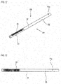
- FIGS. 12 to 17 depict an example of a steering rack and a method for manufacturing the same disclosed in Patent Document 5.
- a steering rack 11a has a rod part 15 made of a metal material such as carbon steel, stainless steel or the like and having a round cross section and a plurality of rack teeth 16 formed on a radial one side surface of a part in the axial direction (a left part in FIGS. 12 to 14 ) of the rod part 15 by plastic processing.
- the rod part 15 is integrally formed over its entire length by the metal material.
- a part in the axial direction of the rod part 15 and is spaced circumferentially from a part on which the plurality of rack teeth 16 is formed is referred to as a backside part 17.
- a radius of curvature R 17 (refer to FIG. 15 ) of the cross section of the backside part 17 is made greater than a radius of curvature r 18 (refer to FIG. 15 ) of an outer periphery of a cylindrical part 18, which is the other part in the axial direction (a right part in FIGS. 12 to 14 ) of the rod part 15 (R 17 >r 18 ).
- FIG. 16A a cylindrical material 19 made of a metal material such as carbon steel, stainless steel or the like is set (placed) in a concave groove portion 21 provided on an upper surface of a receiving die 20 and having an arc-shaped cross section.
- FIG. 16B mounting processing of strongly pressing the material 19 toward the concave groove portion 21 by a tip surface (lower end surface) of a pressing punch 22, which is long along the concave groove portion 21, is performed.
- FIG. 16B mounting processing of strongly pressing the material 19 toward the concave groove portion 21 by a tip surface (lower end surface) of a pressing punch 22, which is long along the concave groove portion 21, is performed.
- the intermediate material 23 has, on its outer periphery, a partially cylindrical surface part 24 which is to be the backside part 17 (refer to FIGS. 12 , 14 and 15 ), a flat surface part 25 located at an opposite side to the partially cylindrical surface part 24 with respect to a radial direction of the cross section, and a pair of curved surface parts 26, 26 configured to continuously connect the partially cylindrical surface part 24 and the flat surface part 25 and having a relatively small radius of curvature.
- the intermediate material 23 is pulled out from the concave groove portion 21 of the receiving die 20 and is inserted (set) into a bottom 29 of a holding hole 28 provided to a die 27.
- a radius of curvature of the bottom 29 is substantially the same as a radius of curvature of an inner surface of the concave groove portion 21 of the receiving die 20.
- both inner surfaces 30, 30 are planar surfaces parallel with each other.
- upper openings are provided with a pair of inclined guide surface portions 31, 31, which are inclined in a direction in which an interval therebetween gradually increases toward the above.
- a tooth-forming punch 32 is inserted into the holding hole 28 and the intermediate material 23 is strongly pushed into the holding hole 28 by the tooth-forming punch 32, as shown in FIGS. 16C and 16D .
- a processing surface (lower surface) of the tooth-forming punch 32 is provided with a rack tooth processing concave and convex 40 having a shape corresponding to the rack teeth 16 to be formed.
- the outer periphery of the intermediate material 23 is restrained by the inner surfaces of the holding hole 28, except for the flat surface part 25 on which the rack teeth 16 are to be formed.
- the intermediate material 23 is strongly pushed into the holding hole 28 by the tooth-forming punch 32, the flat surface part 25 of the intermediate material 23 is plastically deformed in conformity to the rack tooth processing concave and convex 40, so that the intermediate material is processed into a base rack 33 having rack teeth 16 as shown in FIGS. 16D and 17A .
- the base rack 33 is insufficient in terms of shape accuracy and size accuracy, as compared to the completed steering rack 11a (refer to FIGS. 12 to 15 ), and end edges of the rack teeth 16 are sharp.
- the base rack 33 is pulled out from the holding hole 28, and is placed on a sizing concave and convex surface part 36 formed on an upper surface of a sizing die 35, as shown in FIG. 16E .
- the base rack 33 is vertically inverted.
- the sizing concave and convex surface part 36 has a shape (an concave and convex is inverted with respect to a completed shape) corresponding to the shape of the rack teeth 16 to be obtained, including chamfered portions of end edges of the teeth.
- the part of the base rack 33 having the rack teeth 16 formed thereon is strongly pressed toward the sizing concave and convex surface part 36 by a press die 37.
- a lower surface of the press die 37 is formed with a pressing concave groove 38 having a radius of curvature coinciding with the radius of curvature R 17 (refer to FIG. 15 ) of the backside part 17 of the completed steering rack 11a.
- the base rack 33 is strongly pressed toward the sizing concave and convex surface part 36 at a state where a part to be the backside part 17 is fitted in the pressing concave groove 38.
- a tooth 39 of the tooth-forming punch 32 configured to form a rack tooth 16, which is adjacent to an intermediate part in the axial direction, of a plurality of teeth 39 configuring the rack tooth processing concave and convex 40 of the tooth-forming punch 32 is applied with equivalent forces f 1 from the rack teeth 16 of both axial sides at the same tooth height.
- a tooth 39 of the tooth-forming punch 32 configured to form both ends of a rack tooth 16 in the axial direction (in FIGS.
- the present invention has been made in view of the above situations, and an object of the present invention is to provide a steering rack and a method for manufacturing the same capable of implementing a long lifetime of a tooth-forming punch when cold forging is performed.
- the steering rack of the present invention is provided with the at least one dummy tooth, which has the tooth height less than the rack teeth and is configured not to mesh with the pinion, at the portions adjacent to both axial sides of the plurality of rack teeth configured to mesh with the pinion. Therefore, when forming the plurality of rack teeth on the steering rack by cold forging, the tooth of the tooth-forming punch configured to form the rack tooth of each of both axial ends and positioned at the axially outer side of the corresponding rack tooth is applied with the force from the rack tooth of the axially inner side and the force from the dummy tooth of the axially outer side. Therefore, since the balance of the moments to be applied to the teeth of the tooth-forming punch is improved, it is possible to prevent the stress from being concentrated on the teeth, thereby implementing the long lifetime of the tooth-forming punch.
- a steering rack and a method for manufacturing the same according to the present invention have features that when forming the rack teeth 16 on the radial one side surface of a part in the axial direction of the rod part 15 configuring the steering rack 11a (processes corresponding to FIGS. 16C and 16D described above), the stress is prevented from being concentrated on the teeth 39 of the tooth-forming punch 32 and the long lifetime of the tooth-forming punch 32 is thus implemented. Since the other configurations and operational effects are the same as the conventionally known steering rack manufacturing method and manufacturing apparatus, including the conventional manufacturing method and manufacturing apparatus shown in FIGS. 16 to 18 , the illustration and description on the equivalent parts are omitted or simplified.
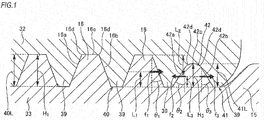
- a tooth-forming punch 32 of a first embodiment has not only the above-described rack tooth processing concave and convex 40 but also dummy tooth processing concave and convex 41 at parts adjacent to both axial sides of the rack tooth processing concave and convex 40 (in FIG. 1 , only the dummy tooth processing concave and convex 41 on one side in the axial direction is shown).
- a tooth height 41 L of the dummy tooth processing concave and convex 41 is formed less than a tooth height 40L of the rack tooth processing concave and convex 40.
- the flat surface part 25 of the intermediate material 23 is plastically deformed in conformity to the rack tooth processing concave and convex 40 and the dummy tooth processing concave and convex 41 and is thus processed to a base rack 33 having rack teeth 16 and dummy teeth 42 as shown in FIG. 1 .
- the base rack 33 has an axially extending rod part 15 having a round cross section and a plurality of rack teeth 16 formed on a radial one side surface of a part in the axial direction of the rod part 15 and configured to mesh with the pinion.
- the dummy tooth 42 has an axially inner surface 42a and an axially outer surface 42b configured to be inclined in a direction of axially coming close to each other as they go toward a radially outer side, and a radially outer surface 42c configured to connect the axially inner surface 42a and the axially outer surface 42b.
- the radially outer surface 42c is a curved surface having an R-shaped cross section of which an axially intermediate part is convex, and is configured to smoothly connect the axially inner surface 42a and the axially outer surface 42b. Therefore, a pair of connection parts 42d consisting of the axially inner surface 42a and axially outer surface 42b and the radially outer surface 42c also has an R shape.
- the dummy tooth 42 is configured not to mesh with the pinion, there is no problem even when the radially outer surface 42c, which is a tooth tip, and the pair of connection parts 42d are made to have the R shape.
- the rack tooth 16 has an axially inner surface 16a and an axially outer surface 16b configured to be inclined in the direction of axially coming close to each other as they go toward the radially outer side, and a radially outer surface 16c configured to connect the axially inner surface 16a and the axially outer surface 16b.
- the radially outer surface 16c is formed to be a planar shape, and a pair of connection parts 16d between the axially inner surface 16a and the radially outer surface 16c and between the axially outer surface 16b and the radially outer surface 16c has an angled shape.
- L 2 H 1 -L 3 is denoted.
- a force f 1 is generated on the axially outer surface 16b of the rack tooth 16 positioned at each of both axial ends toward an axially outer side at a position of L 1 distant from a radially outer end part of the corresponding rack tooth 16 toward a radially inner side.
- a force f 2 is generated on the axially inner surface 42a of the dummy tooth 42 toward an axially inner side at a position of L 2 distant from the radially outer end part of the rack tooth 16 positioned at each of both axial ends toward the radially inner side.
- a force f 3 is generated on the axially outer surface 42b of the dummy tooth 42 toward the axially outer side at a position of L 3 distant from the radially outer end part of the dummy tooth 42 toward the radially inner side.
- the moment L 1 ⁇ f 1 is generated on the axially outer surface 16b of the rack tooth 16
- the moment L 2 ⁇ f 2 is generated on the axially inner surface 42a of the dummy tooth 42
- the moment L 3 ⁇ f 3 is generated on the axially outer surface 42b of the dummy tooth 42.
- the tooth 39 of the tooth-forming punch 32 positioned at each of both ends is applied with the moment L 3 ⁇ f 3 from the dummy tooth 42 of the axially inner side.
- the moment L 3 ⁇ f 3 is less than the moment L 1 ⁇ f 1 , which is to be applied to the tooth 39 of the tooth-forming punch 32 when manufacturing the steering rack of the related art (refer to FIG. 20 ) (L 3 ⁇ f 3 ⁇ L 1 ⁇ f 1 because L 3 ⁇ L 1 , f 3 ⁇ f 1 ). Since the balance of the moments is improved in this way, it is possible to prevent the stress from being concentrated on the teeth 39, thereby implementing the long lifetime of the tooth-forming punch 32.
- the radially outer surface 42c and the pair of connection parts 42d of the dummy tooth 42 have the R shape, the stress concentration on the roots of the teeth 39 of the tooth-forming punch 32 in contact with the connection parts 42d is relieved, so that it is possible to implement the additional long lifetime of the tooth-forming punch 32.
- FIG. 2 depicts the tooth-forming punch 32 (corresponding to the tooth-forming punch 32 of FIG. 18 ) where the dummy tooth processing concave and convex 41 is not provided like the related art
- FIG. 3 depicts the tooth-forming punch 32 of the first embodiment.
- the dark part indicates that the tensile stress is high. It can be seen that the considerably high stress is generated at the roots of the teeth 39 of both axial ends of the tooth-forming punch 32 of the related art but the stress to be generated at the roots of the teeth 39 is remarkably reduced in the tooth-forming punch 32 of the first embodiment.
- FIG. 4 depicts an SN diagram of the lifetime of the tooth-forming punch 32. Since the stress to be generated at the roots of the teeth 39 is remarkably reduced in the tooth-forming punch 32 of the first embodiment, as compared to the tooth-forming punch 32 of the related art, the number of cycles to fracture considerably increases and the long lifetime can be thus implemented.
- the dummy tooth 42 is formed one by one at the part that are the part of the rod part 15 in the axial direction and are adjacent to both axial sides of the plurality of rack teeth 15 (refer to FIG. 1 ).
- a plurality of dummy teeth 42 may be formed at a part that is the part of the rod part 15 in the axial direction and is adjacent to each of both axial sides of the plurality of rack teeth 16.
- the n (n: natural number of 2 or greater) dummy teeth 42 are formed at one side in the axial direction.
- inclined angles of the axially inner surfaces 42a of the plurality of dummy teeth 42 are denoted as ⁇ 2 , ⁇ 4 , ..., ⁇ 2n-2 , ⁇ 2n in order from first to n th dummy teeth 42 close to the rack tooth 16
- inclined angles of the axially outer surfaces 42b of the plurality of dummy teeth 42 are denoted as ⁇ 3 , ⁇ 5 , ⁇ 2n-1 , ⁇ 2n+1 in order from the first to n th dummy teeth 42 close to the rack tooth 16
- tooth heights of the plurality of dummy teeth 42 are denoted as H 3 , H 5 , ⁇ , H 2n-1 , H 2n+1 in order from the first to n th dummy teeth 42, the tooth heights are set so that a relation of H 1 >H 3 >H 5 >...>H 2n-1 >H 2n+1 is satisfied.
- a force f 1 is generated on the axially outer surface 16b of the rack tooth 16 positioned at each of both axial ends toward an axially outer side at a position of L 1 distant from a radially outer end portion of the corresponding rack tooth 16 toward a radially inner side.
- a force f 2 is generated on the axially inner surface 42a of the dummy tooth 42 toward an axially inner side at a position of L 2 distant from the radially outer end portion of the rack tooth 16 positioned at each of both axial ends toward the radially inner side.
- a force f 3 is generated on the axially outer surface 42b of the first dummy tooth 42 toward the axially outer side at a position of L 3 distant from the radially outer end portion of the first dummy tooth 42 toward the radially inner side.
- a force f 4 is generated on the axially inner surface 42a of the second dummy tooth 42 toward the axially inner side at a position of L 4 distant from the radially outer end portion of the first dummy tooth 42 toward the radially inner side.
- a force f 5 is generated on the axially outer surface 42b of the second dummy tooth 42 toward the axially outer side at a position of L 5 distant from the radially outer end portion of the second dummy tooth 42 toward the radially outer side.
- a force f 2n-2 is generated on the axially inner surface 42a of the (n-1) th dummy tooth 42 toward the axially inner side at a position of L 2n-2 distant from the radially outer end portion of the (n-2) th dummy tooth 42 (not shown) toward the radially inner side.
- a force f 2n-1 is generated on the axially outer surface 42b of the (n-1) th dummy tooth 42 toward the axially outer side at a position of L 2n-1 distant from the radially outer end portion of the (n-1) th dummy tooth 42 toward the radially inner side.
- a force f 2n is generated on the axially inner surface 42a of the n th dummy tooth 42 toward the axially inner side at a position of L 2n distant from the radially outer end portion of the (n-1) th dummy tooth 42 toward the radially outer side.
- a force f 2n+1 is generated on the axially outer surface 42b of the n th dummy tooth 42 toward the axially outer side at a position of L 2n+1 distant from the radially outer end portion of the n th dummy tooth 42 toward the radially inner side.
- the moment L 1 ⁇ f 1 is generated on the axially outer surface 16b of the rack tooth 16
- the moment L 2 ⁇ f 2 is generated on the axially inner surface 42a of the first dummy tooth 42
- the moment L 3 ⁇ f 3 is generated on the axially outer surface 42b of the first dummy tooth 42
- the moment L 4 ⁇ f 4 is generated on the axially inner surface 42a of the second dummy tooth 42
- the moment L 2n-1 ⁇ f 2n-1 is generated on the axially outer surface 42b of the (n-1) th dummy tooth 42
- the moment L 2n ⁇ f 2n is generated on the axially inner surface 42a of the n th dummy tooth 42.
- the tooth 39 of the tooth-forming punch 32 configured to form the rack tooth 16 at each of both ends in the axial direction and positioned at the axially outer side of the corresponding rack tooth 16 is applied with the moment L 1 ⁇ f 1 from the rack tooth 16 of the axially inner side and the moment L 2 ⁇ f 2 from the dummy tooth 42 of the axially outer side.
- the tooth 39 (the second tooth 39) adjacent to the axially outer side of the tooth 39 is applied with the moment L 3 ⁇ f 3 from the first dummy tooth 42 of the axially inner side and the moment L 4 ⁇ f 4 from the second dummy tooth 42 of the axially outer side.
- the tooth 39 of the tooth-forming punch 32 positioned at each of both ends is applied with the moment L 2n+1 ⁇ f 2n+1 from the dummy tooth 42 of the axially inner side.
- the moment L 2n+1 ⁇ f 2n+1 is less than the moment L 3 ⁇ f 3 , which is to be applied to the tooth 39 of the tooth-forming punch 32 positioned at each of both ends in the first embodiment (L 2n+1 ⁇ f 2n+1 ⁇ L 3 ⁇ f 3 because L 2n+1 ⁇ L 3 , f 2n+1 ⁇ f 3 ). Since the balance of the moments is improved in this way, as compared to the first embodiment, it is possible to prevent the stress from being concentrated on the teeth 39, thereby implementing the long lifetime of the tooth-forming punch 32.
- the tooth 39 of the tooth-forming punch 32 positioned at each of both end parts is applied with the moment L 3 ⁇ f 3 from the dummy tooth 42 of the axially inner side and is not applied with the moment from the rod part 15 of the axially outer side.
- the present invention is not limited to the corresponding configuration.
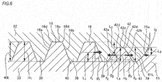
- the moment may be applied from the rod part 15 of the axially outer side.
- the tooth 39 of the tooth-forming punch 32 positioned at each of both end parts and the rod part 15 are axially contacted to each other.
- a force f 0 is generated on the axially inner surface 15a of the rod part 15 toward the axially inner side at a position of L 0 distant from the radially outer end portion of the dummy tooth 42 positioned at each of both ends toward the radially inner side.
- the moment L 0 ⁇ f 0 is generated on the axially inner surface 15a of the rod part 15.
- L 0 is an arbitrary value satisfying a relation of 0 ⁇ L 0 ⁇ H 3 .
- the tooth 39 of the tooth-forming punch 32 positioned at each of both end parts is applied with the moment L 3 ⁇ f 3 from the dummy tooth 42 of the axially inner side and the moment L 0 ⁇ f 0 from the rod part 15 of the axially outer side. Therefore, since the balance of the moments is improved, as compared to the moment L 3 ⁇ f 3 that is to be applied to the teeth 39 of both ends of the tooth-forming punch 32 in the first embodiment, it is possible to prevent the stress from being concentrated on the teeth 39, thereby implementing the long lifetime of the tooth-forming punch 32. This configuration is particularly efficient when it is difficult to increase the number of the dummy teeth 42.
- the tooth 39 of the tooth-forming punch 32 positioned at each of both end parts may be applied with the moment L 2n+1 ⁇ f 2n+1 from the dummy tooth 42 of the axially inner side and the moment L 0 ⁇ f 0 from the rod part 15 of the axially outer side.
- the inclined angles are not necessarily required to be the same.
- the inclined angles are set so that at least a relation of ⁇ 1 ⁇ 2 ⁇ 3 ⁇ 4 ⁇ 5 ⁇ ... ⁇ 2n-2 ⁇ 2 n-1 ⁇ 2n ⁇ 2n+1 is satisfied.
- the radially outer surface 42c of the dummy tooth 42 is not necessarily required to have the curved surface of R-shaped cross section of which the axially intermediate part is convex.
- the radially outer surface 42c of the dummy tooth 42 may have a planar cross section. Also in this configuration, when the pair of connection parts 42d consisting of the axially inner surface 42a and axially outer surface 42b and the radially outer surface 42c is formed to have an R shape, it is possible to relieve the stress concentration on the roots of the teeth 39 of the tooth-forming punch 32 in contact with the connection parts 42d.
- the radially outer surface 42c of the at least one dummy tooth 42 is preferably formed with at least one groove portion 43.
- FIG. 8 depicts an example where a pair of groove portions 43 is formed adjacent to both ends in a width direction of the radially outer surface 42c of the dummy tooth 42, in the first embodiment where the dummy tooth 42 is formed one by one at the parts that are adjacent to both axial sides of the rack teeth 16.
- the pair of groove portions 43 has a substantially linear shape axially extending and enabling the axially inner surface 42a and the axially outer surface 42b to communicate with each other.
- the groove portion 43 has a width size of about 0.5 to 1.0 mm and a depth size of about 0.5 to 1.0 mm.
- the dummy tooth 42 is configured not to mesh with the pinion, as described above, there is no problem even when the groove portion 43 is provided on the radially outer surface 42c which is a tooth end.
- the groove portion 43 is used as a reference when positioning the steering rack 11a in a post process after the forging.
- the positioning is performed by operating a probe having the same shape as the groove portion 43 toward the groove portion 43 and engaging the same with the groove portion 43.
- each of the pair of dummy teeth 42 provided at the parts adjacent to both axial sides of the rack teeth 16 (in FIG. 8 , only one axial dummy tooth 42 is shown) is provided with the pair of groove portions 43, so that a total of four groove portions 43 are provided. Therefore, the four probes are engaged with the four groove portions for positioning, so that the positioning can be made with higher precision.
- the pair of dummy teeth 42 provided at the portions adjacent to both axial sides of the rack teeth 16 has the same tooth height. Therefore, it is possible to level the steering rack 11a by engaging the four probes with the four groove portions 43 to detect positions of the respective groove portions 43 and confirming that the horizontal positions of the at least three groove portions 43 are the same. Therefore, for the leveling, it is necessary to form a total of three or more groove portions 43 on the plurality of dummy teeth 42 having the same tooth height.
- the dummy tooth processing concave and convex 41 of the tooth-forming punch 32 (refer to FIG. 1 and the like) is formed with a protrusion (not shown) having a shape corresponding to the groove portion 43.
- the tooth-forming punch 32 has the rack tooth processing concave and convex 40, the dummy tooth processing concave and convex 41 and the protrusion, it is possible to form the rack teeth 16, the dummy tooth 42 and the groove portion 43 on the steering rack 11a at the same time. Therefore, since it is not necessary to process the groove portion 43 in a separate process, it is possible to prevent increases in the working hours and costs.
- the groove portions 43 are provided on the dummy teeth 42 of the first embodiment.
- the groove portions 43 may be provided on the dummy teeth 42.
- the radially outer surface 42c of the at least one dummy tooth 42 is formed with the at least one groove portion 43, the positioning of the steering rack 11a can be performed.
- the leveling is possible.
- the shape of the groove portion 43 is not particularly limited inasmuch as it can be used as a reference of the positioning or leveling of the steering rack 11a.
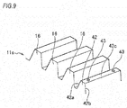
- a substantially semispherical shape as shown in FIG. 9 is also possible.
- the groove portion 43 has a diameter size of about 0.5 to 1.0 mm and a depth size of about 0.5 to 1.0 mm.
Landscapes
- Engineering & Computer Science (AREA)
- Mechanical Engineering (AREA)
- General Engineering & Computer Science (AREA)
- Chemical & Material Sciences (AREA)
- Combustion & Propulsion (AREA)
- Transportation (AREA)
- Gears, Cams (AREA)
- Power Steering Mechanism (AREA)
- Forging (AREA)
Abstract
Description
- The present invention relates to a steering rack and a method for manufacturing the same.
- For example, as shown in
FIG. 10 , an automotive steering device configured to apply a steering angle to steering wheels of an automobile (generally, front wheels except for a special vehicle such as a forklift) is configured to transmit movement of asteering shaft 2 configured to rotate in accordance with an operation of asteering wheel 1 to an input shaft 6 of asteering gear 5 via universal joints 3, 3 and an intermediate shaft 4. Thesteering gear 5 has a pinion configured to rotate by the input shaft 6 and a steering rack configured to mesh with the pinion. When the pinion rotates together with the input shaft 6, the steering rack is axially displaced to push and pull a pair of tie-rods - Also, a gear housing 9 is coupled to a lower end of a
steering column 8 in which thesteering shaft 2 is inserted. The gear housing 9 is configured to support anelectric motor 10. By theelectric motor 10, an auxiliary force of a rotating direction is applied to thesteering shaft 2. - Meanwhile, in addition to the column-assisted electric power steering device shown in
FIG. 10 , electric power steering devices called as a pinion-assisted type, a dual pinion-assisted type and a rack-assisted type have been used.FIG. 11 depicts a steering device in which a dual pinion-assisted power steering device is incorporated. The steering device has asecond input shaft 12 arranged at a part that is an axial part of a steering rack 11 and is spaced from a pinion provided on an outer periphery of the input shaft 6. A second pinion provided on an outer periphery of one end portion of thesecond input shaft 12 is configured to mesh with the steering rack 11. Also, anelectric motor 10a is supported to a lateral side of ahousing 13 in which thesecond input shaft 12 is provided. By theelectric motor 10a, a force of a rotating direction is applied to thesecond input shaft 12 via adecelerator 14. Therefore, the steering rack 11 is axially displaced by a force based on the auxiliary force and a force applied from the input shaft 6 on the basis of a force applied to thesteering wheel 1 by a driver. - In the shown example, a plurality of rack teeth is axially provided on a radial one side surface of the steering rack 11, except for both end portions coupled to the pair of tie-
rods 7, 7 (refer toFIG. 10 ). A pitch of the pinion provided on the outer periphery of the input shaft 6 and a pitch of the second pinion provided on the outer periphery of the one end portion of thesecond input shaft 12 can be made to be different from each other can be made to be different from each other. An angle between a central axis of the input shaft 6 and a central axis of the steering rack 11 and an angle between a central axis of thesecond input shaft 12 and the central axis of the steering rack 11 can be made to be different from each other. - When the rack for the steering gear is made by performing cutting processing for a material to form a plurality of rack teeth, the manufacturing cost increases and it is difficult to secure the strength and stiffness of the rack. In contrast, when the rack teeth are formed by plastically deforming a material by cold forging, it is possible to shorten time necessary for processing of the rack teeth and to reduce the manufacturing cost because it is not necessary to perform finishing processing after the quenching. Also, since a metal structure of the obtained rack is dense and a sectional shape of the rack can be deformed upon the plastic deformation, as required, it is easy to secure the strength and stiffness of the rack. The steering rack manufacturing method of processing the rack teeth by the cold forging in this way has been known in
Patent Documents 1 to 5, for example. -
FIGS. 12 to 17 depict an example of a steering rack and a method for manufacturing the same disclosed inPatent Document 5. Asteering rack 11a has arod part 15 made of a metal material such as carbon steel, stainless steel or the like and having a round cross section and a plurality ofrack teeth 16 formed on a radial one side surface of a part in the axial direction (a left part inFIGS. 12 to 14 ) of therod part 15 by plastic processing. Therod part 15 is integrally formed over its entire length by the metal material. Herein, a part in the axial direction of therod part 15 and is spaced circumferentially from a part on which the plurality ofrack teeth 16 is formed is referred to as abackside part 17. In the shown example, a radius of curvature R17 (refer toFIG. 15 ) of the cross section of thebackside part 17 is made greater than a radius of curvature r18 (refer toFIG. 15 ) of an outer periphery of acylindrical part 18, which is the other part in the axial direction (a right part inFIGS. 12 to 14 ) of the rod part 15 (R17>r18). According to this structure, while sufficiently securing a width size, stiffness and strength of therack teeth 16, it is possible to suppress an outer diameter of a part except for the part on which therack teeth 16 is formed from increasing beyond necessity, thereby reducing a weight. - Subsequently, a manufacturing method of the above-described
steering rack 11a is described with reference toFIGS. 16 to 18 . First, as shown inFIG. 16A , acylindrical material 19 made of a metal material such as carbon steel, stainless steel or the like is set (placed) in aconcave groove portion 21 provided on an upper surface of a receiving die 20 and having an arc-shaped cross section. Then, as shown inFIG. 16B , mounting processing of strongly pressing thematerial 19 toward theconcave groove portion 21 by a tip surface (lower end surface) of apressing punch 22, which is long along theconcave groove portion 21, is performed. In the mounting processing shown inFIG. 16B , a part in an axial direction of thematerial 19 on which the rack teeth 16 (refer toFIGS. 12 to 15 ) are to be formed is crushed in a vertical direction and a width size in a horizontal direction is increased, so that anintermediate material 23 is formed. Theintermediate material 23 has, on its outer periphery, a partiallycylindrical surface part 24 which is to be the backside part 17 (refer toFIGS. 12 ,14 and 15 ), aflat surface part 25 located at an opposite side to the partiallycylindrical surface part 24 with respect to a radial direction of the cross section, and a pair ofcurved surface parts cylindrical surface part 24 and theflat surface part 25 and having a relatively small radius of curvature. - Subsequently, as shown in
FIG. 16C , theintermediate material 23 is pulled out from theconcave groove portion 21 of the receiving die 20 and is inserted (set) into abottom 29 of aholding hole 28 provided to adie 27. A radius of curvature of thebottom 29 is substantially the same as a radius of curvature of an inner surface of theconcave groove portion 21 of the receivingdie 20. Also, bothinner surfaces guide surface portions - When the
intermediate material 23 is set in theholding hole 28 of thedie 27, a tooth-formingpunch 32 is inserted into theholding hole 28 and theintermediate material 23 is strongly pushed into theholding hole 28 by the tooth-formingpunch 32, as shown inFIGS. 16C and 16D . A processing surface (lower surface) of the tooth-formingpunch 32 is provided with a rack tooth processing concave and convex 40 having a shape corresponding to therack teeth 16 to be formed. Also, the outer periphery of theintermediate material 23 is restrained by the inner surfaces of theholding hole 28, except for theflat surface part 25 on which therack teeth 16 are to be formed. For this reason, when theintermediate material 23 is strongly pushed into theholding hole 28 by the tooth-formingpunch 32, theflat surface part 25 of theintermediate material 23 is plastically deformed in conformity to the rack tooth processing concave and convex 40, so that the intermediate material is processed into abase rack 33 havingrack teeth 16 as shown inFIGS. 16D and17A . At this state, thebase rack 33 is insufficient in terms of shape accuracy and size accuracy, as compared to the completedsteering rack 11a (refer toFIGS. 12 to 15 ), and end edges of therack teeth 16 are sharp. Also, since the excess thickness extruded (from portions to be tooth bottoms) as therack teeth 16 are processed is strongly pressed to bothinner surfaces holding hole 28, reliefflat surface parts base rack 33. - Therefore, after uplifting the tooth-forming
punch 32, thebase rack 33 is pulled out from theholding hole 28, and is placed on a sizing concave andconvex surface part 36 formed on an upper surface of asizing die 35, as shown inFIG. 16E . At this time, thebase rack 33 is vertically inverted. The sizing concave andconvex surface part 36 has a shape (an concave and convex is inverted with respect to a completed shape) corresponding to the shape of therack teeth 16 to be obtained, including chamfered portions of end edges of the teeth. Then, as shown inFIGS. 16E and 16F , the part of thebase rack 33 having therack teeth 16 formed thereon is strongly pressed toward the sizing concave andconvex surface part 36 by apress die 37. - A lower surface of the
press die 37 is formed with a pressingconcave groove 38 having a radius of curvature coinciding with the radius of curvature R17 (refer toFIG. 15 ) of thebackside part 17 of the completedsteering rack 11a. Thebase rack 33 is strongly pressed toward the sizing concave andconvex surface part 36 at a state where a part to be thebackside part 17 is fitted in the pressingconcave groove 38. As a result, at a state (FIG. 16F ) where thesizing die 35 and thepress die 37 are sufficiently brought close to each other, therack teeth 16 are in a completed state shown inFIG. 17B (a state where a shape and a size are appropriate and an end edge of each tooth is chamfered) and thebackside part 17 also has appropriate shape and size. In the meantime, the excess thickness extruded by performing the sizing is collected at both reliefflat surface parts flat surface parts steering rack 11a. However, since the excess thickness does not extremely strongly press the inner surfaces of the sizing concave andconvex surface part 36 or the pressingconcave groove 38, it is possible to suppress the processing load of the sizing as low as possible and to easily secure the durability of thesizing die 35 and thepress die 37. -
- Patent Document 1:
Japanese Patent Application Publication No. H10-58081A - Patent Document 2:
Japanese Patent Application Publication No. 2001-79639A - Patent Document 3:
Japanese Patent No. 3,442,298B - Patent Document 4:
Japanese Patent Application Publication No. 2006-103644A - Patent Document 5:
Japanese Patent Application Publication No. 2008-138864A - According to the manufacturing method of the steering rack of the related art, including the manufacturing method disclosed in
Patent Document 5, following problems may occur. As described above, when theintermediate material 23 is strongly pushed into the holdinghole 28 by the tooth-formingpunch 32, theflat surface part 25 of theintermediate material 23 is plastically deformed in conformity to the rack tooth processing concave and convex 40 of the tooth-formingpunch 32 and is processed into thebase rack 33 having the rack teeth 16 (refer toFIG. 18 ). - Herein, as shown in
FIG. 19 (corresponding to an area A surrounded by the broken line ofFIG. 18 ), atooth 39 of the tooth-formingpunch 32 configured to form arack tooth 16, which is adjacent to an intermediate part in the axial direction, of a plurality ofteeth 39 configuring the rack tooth processing concave and convex 40 of the tooth-formingpunch 32 is applied with equivalent forces f1 from therack teeth 16 of both axial sides at the same tooth height. In contrast, as shown inFIG. 20 (corresponding to an area B surrounded by the broken line ofFIG. 18 ), atooth 39 of the tooth-formingpunch 32 configured to form both ends of arack tooth 16 in the axial direction (inFIGS. 18 and20 , only one end of therack tooth 16 in the axial directio n is shown) and positioned at an axially outer side of thecorresponding rack tooth 16 is applied with the force f1 from therack tooth 16 placed in an axially inner side of thet ooth 39. For this reason, the moments applied from both axial sides are unbalanced, bending occurs in thetooth 39 of the tooth-formingpunch 32, stress is concentrated on a corner of a root of thetooth 39, strong tensile force is thus generated, and the lifetime of the tooth-formingpunch 32 may be shortened. In the worst case, a crack C is generated at the corner of the root of thetooth 39, so that the tooth may be fractured. - The present invention has been made in view of the above situations, and an object of the present invention is to provide a steering rack and a method for manufacturing the same capable of implementing a long lifetime of a tooth-forming punch when cold forging is performed.
- The above object of the present invention is achieved by following configurations.
- (1) A steering rack configured to mesh with a pinion configured to be rotationally driven by an input shaft of a steering gear configuring an automotive steering device, wherein
the steering rack has a rod part extending in an axial direction and having a round cross section and a plurality of rack teeth formed on a radial one side surface of a part of the rod part in the axial direction and configured to mesh with the pinion, and
at least one dummy tooth having a tooth height less than the rack teeth and configured not to mesh with the pinion is formed at parts that are the parts of the rod part in the axial direction and are adjacent to both axial sides of the plurality of rack teeth. - (2) In the steering rack of (1), wherein
the dummy tooth has an axially inner surface and an axially outer surface configured to be inclined in a direction of axially coming close to each other as they go toward a radially outer side, and a radially outer surface configured to connect the axially inner surface and the axially outer surface, and
a pair of connection parts between the axially inner surface and the radially outer surface and between the axially outer surface and the radially outer surface has an R shape. - (3) In the steering rack of (2), wherein
the n (n: natural number) dummy teeth are formed at the parts that are the parts of the rod part in the axial direction and are adjacent to both axial sides of the plurality of rack teeth,
each of the rack teeth has an axially inner surface and an axially outer surface configured to be inclined in a direction of axially coming close to each other as they go toward a radially outer side, and a radially outer surface configured to connect the axially inner surface and the axially outer surface, and
when an inclined angle of the axially outer surface, which is adjacent to the dummy tooth, of the rack tooth, which is positioned at each of both axial ends, of the plurality of rack teeth is denoted as θ1,
inclined angles of the axially inner surfaces of the plurality of dummy teeth are denoted as θ2, θ4, θ2n in order from first to nth dummy teeth close to the rack tooth, and
inclined angles of the axially outer surfaces of the plurality of dummy teeth are denoted as θ3, θ5, ···, θ2n+1 in order from the first to nth dummy teeth close to the rack tooth,
the inclined angles are set so that a relation of θ1<θ2≤θ3<θ4≤θ5<...<θ2n≤θ2n+1 is satisfied. - (4) In the steering rack of (3), wherein
when a tooth height of the rack tooth positioned at each of both ends in the axial direction is denoted as H1 and tooth heights of the plurality of dummy teeth are denoted as H3, H5, ···, H2n+1 in order from the first to nth dummy teeth, the tooth heights are set so that a relation of H1>H3H5>...>H2n+1 is satisfied. - (5) In the steering rack of (4), wherein
when a half value of the tooth height of the rack tooth positioned at each of both ends in the axial direction is denoted as L1 and half values of the tooth heights H3, H5, ···, H2n+1 of the first to nth dummy teeth are denoted as L3, L5, ···, L2n+1, a relation of L2=H1-L3, L4=H3-L5, ···, L2n=H2n-1-L2n+1 is satisfied, and
when a force, which is to be generated on the axially outer surface of the rack tooth positioned at each of both ends in the axial direction toward an axially outer side at a position of L1 distant from a radially outer end portion of the corresponding rack tooth toward a radially inner side, is denoted as f1,
a force, which is to be generated on the axially inner surface of the first dummy tooth toward an axially inner side at a position of L2 distant from the radially outer end portion of the rack tooth positioned at each of both axial ends toward the radially inner side, is denoted as f2,
a force, which is to be generated on the axially outer surface of the (n-1)th dummy tooth toward the axially outer side at a position of L2n-1 distant from the radially outer end portion of the (n-1)th dummy tooth toward the radially inner side, is denoted as f2n-1, and
a force, which is to be generated on the axially inner surface of the nth dummy tooth toward the axially inner side at a position of L2n distant from the radially outer end portion of the (n-1)th dummy tooth toward the radially inner side, is denoted as f2n,
a relation of L1×f1=L2×f2, L3×f3=L4×f4, ···, L2n-1×f2n-1=L2n×f2n is satisfied. - (6) In the steering rack of any one of (1) to (5), wherein
the radially outer surface of the at least one dummy tooth is formed with at least one groove portion. - (7) In the steering rack of (6),
wherein the groove portion is formed in total of three or more on the plurality of dummy teeth having the same tooth height. - (8) A method of manufacturing a steering rack, comprising forming a plurality of rack teeth on a radial one side surface of a part of a rod part, which is extending in the axial direction and is made of a metal material, in an axial direction by pressing a tooth-forming punch having rack tooth processing concave and convex having a rack shape toward the radial one side surface and plastically deforming the radial one side surface, wherein
the plurality of rack teeth is configured to mesh with a pinion configured to be rotationally driven by an input shaft of a steering gear configuring an automotive steering device,
the tooth-forming punch has dummy tooth processing concave and convex of which a tooth height is less than the rack tooth processing concave and convex at parts adjacent to both axial sides of the rack tooth processing concave and convex, and
at least one dummy tooth having a tooth height less than the rack teeth and configured not to mesh with the pinion is formed at parts that are the parts of the rod part in the axial direction and are adjacent to both axial sides of the plurality of rack teeth. - (9) In the method of (8), wherein
in the process of forming the rack teeth, axially outer surfaces of teeth positioned at both end parts of the tooth-forming punch in the axial direction are contacted to axially inner surfaces of the rod part. - (10) In the method of (9),wherein
the dummy tooth processing concave and convex has at least one protrusion, and
a radially outer surface of the at least one dummy tooth is formed with at least one groove portion by the protrusion. - The steering rack of the present invention is provided with the at least one dummy tooth, which has the tooth height less than the rack teeth and is configured not to mesh with the pinion, at the portions adjacent to both axial sides of the plurality of rack teeth configured to mesh with the pinion. Therefore, when forming the plurality of rack teeth on the steering rack by cold forging, the tooth of the tooth-forming punch configured to form the rack tooth of each of both axial ends and positioned at the axially outer side of the corresponding rack tooth is applied with the force from the rack tooth of the axially inner side and the force from the dummy tooth of the axially outer side. Therefore, since the balance of the moments to be applied to the teeth of the tooth-forming punch is improved, it is possible to prevent the stress from being concentrated on the teeth, thereby implementing the long lifetime of the tooth-forming punch.
-
-
FIG. I depicts a rack and a tooth-forming punch according to a first embodiment of the present invention. -
FIG. 2 depicts a stress distribution that is to occur in a tooth-forming punch of the related art. -
FIG. 3 depicts a stress distribution that is to occur in a tooth-forming punch of the present invention. -
FIG. 4 is an SN diagram of a lifetime of the tooth-forming punch of the present invention. -
FIG. 5 depicts a rack and a tooth-forming punch according to a second embodiment of the present invention. -
FIG. 6 depicts a rack and a tooth-forming punch according to a modified embodiment. -
FIG. 7 depicts a rack and a tooth-forming punch according to a modified embodiment. -
FIG. 8 is a perspective view depicting a rack according to a modified embodiment. -
FIG. 9 is a perspective view depicting a rack according to a modified embodiment. -
FIG. 10 is a partially sectional view depicting a first example of the conventional structure of an automotive steering device having a steering gear in which a steering rack is incorporated. -
FIG. 11 is a partially sectional view depicting a second example of the conventional structure of an automotive steering device having a steering gear in which a steering rack is incorporated. -
FIG. 12 is a perspective view depicting the steering rack. -
FIG. 13 is a view, as seen from a XIII arrow direction ofFIG. 12 . -
FIG. 14 is a view, as seen from a XIV arrow direction ofFIG. 12 . -
FIG. 15 is a sectional view taken along a line XV-XV ofFIG. 14 . -
FIGS. 16A to 16F are sectional views as seen from the same direction asFIG. 15 , depicting a method of manufacturing the steering rack relating to the conventional structure in a process sequence. -
FIGS. 17A and 17B are partial perspective views depicting shapes of rack teeth before and after sizing. -
FIG. 18 is a sectional view for illustrating problems of a method and an apparatus for manufacturing the rack of the related art. -
FIG. 19 is an enlarged sectional view corresponding to an area A ofFIG. 18 . -
FIG. 20 is an enlarged sectional view corresponding to an area B ofFIG. 18 . - Hereinafter, a steering rack according to each embodiment of the present invention will be described in detail with reference to the drawings.
- A steering rack and a method for manufacturing the same according to the present invention have features that when forming the
rack teeth 16 on the radial one side surface of a part in the axial direction of therod part 15 configuring thesteering rack 11a (processes corresponding toFIGS. 16C and 16D described above), the stress is prevented from being concentrated on theteeth 39 of the tooth-formingpunch 32 and the long lifetime of the tooth-formingpunch 32 is thus implemented. Since the other configurations and operational effects are the same as the conventionally known steering rack manufacturing method and manufacturing apparatus, including the conventional manufacturing method and manufacturing apparatus shown inFIGS. 16 to 18 , the illustration and description on the equivalent parts are omitted or simplified. - As shown in
FIG. 1 , a tooth-formingpunch 32 of a first embodiment has not only the above-described rack tooth processing concave and convex 40 but also dummy tooth processing concave and convex 41 at parts adjacent to both axial sides of the rack tooth processing concave and convex 40 (inFIG. 1 , only the dummy tooth processing concave and convex 41 on one side in the axial direction is shown). Atooth height 41 L of the dummy tooth processing concave and convex 41 is formed less than atooth height 40L of the rack tooth processing concave and convex 40. - Therefore, when strongly pushing the
intermediate material 23 into the holdinghole 28 by the tooth-forming punch 32 (processes corresponding toFIGS. 16C and 16D ), theflat surface part 25 of theintermediate material 23 is plastically deformed in conformity to the rack tooth processing concave and convex 40 and the dummy tooth processing concave and convex 41 and is thus processed to abase rack 33 havingrack teeth 16 anddummy teeth 42 as shown inFIG. 1 . - More specifically, the
base rack 33 has an axially extendingrod part 15 having a round cross section and a plurality ofrack teeth 16 formed on a radial one side surface of a part in the axial direction of therod part 15 and configured to mesh with the pinion. Adummy tooth 42 is formed one by one at parts that are parts of therod part 15 in the axial direction and are adjacent to both sides of the plurality ofrack teeth 16 in the axial direction. Since a tooth height H3 of thedummy tooth 42 is formed less than a tooth height H1 of the rack tooth 15 (H3=41L<H1=40L), thedummy tooth 42 does not mesh with the pinion. - Also, the
dummy tooth 42 has an axiallyinner surface 42a and an axiallyouter surface 42b configured to be inclined in a direction of axially coming close to each other as they go toward a radially outer side, and a radiallyouter surface 42c configured to connect the axiallyinner surface 42a and the axiallyouter surface 42b. The radiallyouter surface 42c is a curved surface having an R-shaped cross section of which an axially intermediate part is convex, and is configured to smoothly connect the axiallyinner surface 42a and the axiallyouter surface 42b. Therefore, a pair ofconnection parts 42d consisting of the axiallyinner surface 42a and axiallyouter surface 42b and the radiallyouter surface 42c also has an R shape. In the meantime, as described above, since thedummy tooth 42 is configured not to mesh with the pinion, there is no problem even when the radiallyouter surface 42c, which is a tooth tip, and the pair ofconnection parts 42d are made to have the R shape. - The
rack tooth 16 has an axiallyinner surface 16a and an axiallyouter surface 16b configured to be inclined in the direction of axially coming close to each other as they go toward the radially outer side, and a radiallyouter surface 16c configured to connect the axiallyinner surface 16a and the axiallyouter surface 16b. Herein, since therack tooth 16 is configured to mesh with the pinion, the radiallyouter surface 16c is formed to be a planar shape, and a pair ofconnection parts 16d between the axiallyinner surface 16a and the radiallyouter surface 16c and between the axiallyouter surface 16b and the radiallyouter surface 16c has an angled shape. - When an inclined angle of the axially
outer surface 16b, which is adjacent to thedummy tooth 42, of the rack tooth 16 (therack tooth 16 positioned at the rightmost side inFIG. 1 ), which is positioned at each of both axial ends, of the plurality ofrack teeth 16 is denoted as θ1, an inclined angle of the axiallyinner surface 42a of thedummy tooth 42 is denoted as θ2, and an inclined angle of the axiallyouter surface 42b of the dummy tooth is denoted as θ3, the angles are set so that a relation of θ1<θ2=θ3 is satisfied. - Also, a half value of the tooth height H1 of the rack tooth positioned at each of both axial ends is denoted as L1 (L1=0.5×H1), a half value of the tooth height H3 of the
dummy tooth 42 is denoted as L3(L3=0.5×H3), and L2=H1-L3 is denoted. In this case, a force f1 is generated on the axiallyouter surface 16b of therack tooth 16 positioned at each of both axial ends toward an axially outer side at a position of L1 distant from a radially outer end part of thecorresponding rack tooth 16 toward a radially inner side. Also, a force f2 is generated on the axiallyinner surface 42a of thedummy tooth 42 toward an axially inner side at a position of L2 distant from the radially outer end part of therack tooth 16 positioned at each of both axial ends toward the radially inner side. Also, a force f3 is generated on the axiallyouter surface 42b of thedummy tooth 42 toward the axially outer side at a position of L3 distant from the radially outer end part of thedummy tooth 42 toward the radially inner side. Herein, since the angles are set so that the relation of θ1<θ2=θ3 is satisfied, as described above, a relation of f1>f2=f3 is satisfied by a wedge effect. Also, variation of 0.5×H1<H1-0.5×H3 is made due to H1>H3, and a relation of L1<L2 is satisfied due to L1=0.5×H1, L3=0.5×H3 and L2=H1-L3. - Therefore, the moment L1×f1 is generated on the axially
outer surface 16b of therack tooth 16, the moment L2×f2 is generated on the axiallyinner surface 42a of thedummy tooth 42, and the moment L3×f3 is generated on the axiallyouter surface 42b of thedummy tooth 42. Herein, since θ2, L2(H3) and the like can be freely designed, the moments are designed so that a relation of L1×f1=L2×f2 is satisfied. - According to the above configuration, the
tooth 39 of the tooth-formingpunch 32 configured to form therack tooth 16 of each of both axial ends and positioned at the axially outer side of thecorresponding rack tooth 16 is applied with the moment L1×f1 from therack tooth 16 of the axially inner side and the moment L2×f2 from thedummy tooth 42 of the axially outer side. Therefore, the moments applied to thetooth 39 of the tooth-formingpunch 32 are balanced (L1×f1=L2×f2). - Also, the
tooth 39 of the tooth-formingpunch 32 positioned at each of both ends is applied with the moment L3×f3 from thedummy tooth 42 of the axially inner side. The moment L3×f3 is less than the moment L1×f1, which is to be applied to thetooth 39 of the tooth-formingpunch 32 when manufacturing the steering rack of the related art (refer toFIG. 20 ) (L3×f3<L1×f1 because L3<L1, f3<f1). Since the balance of the moments is improved in this way, it is possible to prevent the stress from being concentrated on theteeth 39, thereby implementing the long lifetime of the tooth-formingpunch 32. - Further, since the radially
outer surface 42c and the pair ofconnection parts 42d of thedummy tooth 42 have the R shape, the stress concentration on the roots of theteeth 39 of the tooth-formingpunch 32 in contact with theconnection parts 42d is relieved, so that it is possible to implement the additional long lifetime of the tooth-formingpunch 32. - The reduction in the tensile stress, which is to be generated on the roots of the
teeth 39 of the tooth-formingpunch 32, by thedummy tooth 42 is also clear from evaluation results of an elastic-plastic analysis shown inFIGS. 2 and 3. FIG. 2 depicts the tooth-forming punch 32 (corresponding to the tooth-formingpunch 32 ofFIG. 18 ) where the dummy tooth processing concave and convex 41 is not provided like the related art, andFIG. 3 depicts the tooth-formingpunch 32 of the first embodiment. InFIGS. 2 and 3 , the dark part indicates that the tensile stress is high. It can be seen that the considerably high stress is generated at the roots of theteeth 39 of both axial ends of the tooth-formingpunch 32 of the related art but the stress to be generated at the roots of theteeth 39 is remarkably reduced in the tooth-formingpunch 32 of the first embodiment. - Also,
FIG. 4 depicts an SN diagram of the lifetime of the tooth-formingpunch 32. Since the stress to be generated at the roots of theteeth 39 is remarkably reduced in the tooth-formingpunch 32 of the first embodiment, as compared to the tooth-formingpunch 32 of the related art, the number of cycles to fracture considerably increases and the long lifetime can be thus implemented. - In the first embodiment, the
dummy tooth 42 is formed one by one at the part that are the part of therod part 15 in the axial direction and are adjacent to both axial sides of the plurality of rack teeth 15 (refer toFIG. 1 ). However, as shown inFIG. 5 , a plurality ofdummy teeth 42 may be formed at a part that is the part of therod part 15 in the axial direction and is adjacent to each of both axial sides of the plurality ofrack teeth 16. - In
FIG. 5 , the n (n: natural number of 2 or greater)dummy teeth 42 are formed at one side in the axial direction. When inclined angles of the axiallyinner surfaces 42a of the plurality ofdummy teeth 42 are denoted as θ2, θ4, ..., θ2n-2, θ2n in order from first to nth dummy teeth 42 close to therack tooth 16, and inclined angles of the axiallyouter surfaces 42b of the plurality ofdummy teeth 42 are denoted as θ3, θ5, θ2n-1, θ2n+1 in order from the first to nth dummy teeth 42 close to therack tooth 16, the inclined angles are set so that a relation of θ1<θ2=θ3<θ4=θ5<... <θ2n-2=θ2n-1<θ2n=θ2n+1 is satisfied. Also, when tooth heights of the plurality ofdummy teeth 42 are denoted as H3, H5, ···, H2n-1, H2n+1 in order from the first to nth dummy teeth 42, the tooth heights are set so that a relation of H1>H3>H5>...>H2n-1 >H2n+1 is satisfied. Also, half values of the tooth heights H3, H5, ···, H2n-1, H2n+1 of thedummy teeth 42 are denoted as L3, L5, ···, L2n-1, L2n+1, and L2=H1-L3, L4=H3-L5, ···, L2n=H2n-1-L2n+1 are denoted. - In this case, a force f1 is generated on the axially
outer surface 16b of therack tooth 16 positioned at each of both axial ends toward an axially outer side at a position of L1 distant from a radially outer end portion of thecorresponding rack tooth 16 toward a radially inner side. Also, a force f2 is generated on the axiallyinner surface 42a of thedummy tooth 42 toward an axially inner side at a position of L2 distant from the radially outer end portion of therack tooth 16 positioned at each of both axial ends toward the radially inner side. Also, a force f3 is generated on the axiallyouter surface 42b of thefirst dummy tooth 42 toward the axially outer side at a position of L3 distant from the radially outer end portion of thefirst dummy tooth 42 toward the radially inner side. Also, a force f4 is generated on the axiallyinner surface 42a of thesecond dummy tooth 42 toward the axially inner side at a position of L4 distant from the radially outer end portion of thefirst dummy tooth 42 toward the radially inner side. Also, a force f5 is generated on the axiallyouter surface 42b of thesecond dummy tooth 42 toward the axially outer side at a position of L5 distant from the radially outer end portion of thesecond dummy tooth 42 toward the radially outer side. Also, a force f2n-2 is generated on the axiallyinner surface 42a of the (n-1)thdummy tooth 42 toward the axially inner side at a position of L2n-2 distant from the radially outer end portion of the (n-2)th dummy tooth 42 (not shown) toward the radially inner side. Also, a force f2n-1 is generated on the axiallyouter surface 42b of the (n-1)thdummy tooth 42 toward the axially outer side at a position of L2n-1 distant from the radially outer end portion of the (n-1)thdummy tooth 42 toward the radially inner side. Also, a force f2n is generated on the axiallyinner surface 42a of the nth dummy tooth 42 toward the axially inner side at a position of L2n distant from the radially outer end portion of the (n-1)thdummy tooth 42 toward the radially outer side. Also, a force f2n+1 is generated on the axiallyouter surface 42b of the nth dummy tooth 42 toward the axially outer side at a position of L2n+1 distant from the radially outer end portion of the nth dummy tooth 42 toward the radially inner side. - Herein, since the inclined angles are set so that the relation of θ1<θ2=θ3<θ4=θ5<...<θ2n-2=θ2n-1<θ2n=θ2n+1 is satisfied, as described above, a relation of f1>f2=f3>f4=f5>...>f2n-2=f2n-1>f2n=f2n+1 is satisfed by a wedge effect. Also, a relation of L1<L2, L3<L4, ···, L2n-1<L2n is satisfied due to H1>H3>H5>...>H2n-1>H2n+1.
- Therefore, the moment L1×f1 is generated on the axially
outer surface 16b of therack tooth 16, the moment L2×f2 is generated on the axiallyinner surface 42a of thefirst dummy tooth 42, the moment L3×f3 is generated on the axiallyouter surface 42b of thefirst dummy tooth 42, the moment L4×f4 is generated on the axiallyinner surface 42a of thesecond dummy tooth 42, the moment L2n-1×f2n-1 is generated on the axiallyouter surface 42b of the (n-1)thdummy tooth 42, and the moment L2n×f2n is generated on the axiallyinner surface 42a of the nth dummy tooth 42. Herein, the moments are designed so that L1×f1=L2×f2, L3×f3=L4×f4 and L2n-1×f2n-1=L2n×f2n and the moments from the left and right are balanced. - According to the above configuration, the
tooth 39 of the tooth-formingpunch 32 configured to form therack tooth 16 at each of both ends in the axial direction and positioned at the axially outer side of thecorresponding rack tooth 16 is applied with the moment L1×f1 from therack tooth 16 of the axially inner side and the moment L2×f2 from thedummy tooth 42 of the axially outer side. Also, the tooth 39 (the second tooth 39) adjacent to the axially outer side of thetooth 39 is applied with the moment L3×f3 from thefirst dummy tooth 42 of the axially inner side and the moment L4×f4 from thesecond dummy tooth 42 of the axially outer side. Also, the nth tooth 39 is applied with the moment L2n-1×f2n-1 from the (n-1)thdummy tooth 42 and the moment L2n×f2n from the nth dummy tooth 42 of the axially outer side. Therefore, the moments that are to be applied to the plurality ofteeth 39 of the tooth-formingpunch 32 are balanced (L1×f1=L1×f2, L3×f3=L4×f4, L2n-1×f2n-1=L2n×f2n). - Also, the
tooth 39 of the tooth-formingpunch 32 positioned at each of both ends is applied with the moment L2n+1×f2n+1 from thedummy tooth 42 of the axially inner side. However, the moment L2n+1×f2n+1 is less than the moment L3×f3, which is to be applied to thetooth 39 of the tooth-formingpunch 32 positioned at each of both ends in the first embodiment (L2n+1×f2n+1<L3×f3 because L2n+1<L3, f2n+1<f3). Since the balance of the moments is improved in this way, as compared to the first embodiment, it is possible to prevent the stress from being concentrated on theteeth 39, thereby implementing the long lifetime of the tooth-formingpunch 32. - In the meantime, the present invention is not limited to the respective embodiments and can be appropriately changed and modified.
- For example, in the first embodiment (refer to
FIG. 1 ), thetooth 39 of the tooth-formingpunch 32 positioned at each of both end parts is applied with the moment L3×f3 from thedummy tooth 42 of the axially inner side and is not applied with the moment from therod part 15 of the axially outer side. However, the present invention is not limited to the corresponding configuration. For example, as shown inFIG. 6 , the moment may be applied from therod part 15 of the axially outer side. - In this case, the
tooth 39 of the tooth-formingpunch 32 positioned at each of both end parts and therod part 15 are axially contacted to each other. Also, a force f0 is generated on the axiallyinner surface 15a of therod part 15 toward the axially inner side at a position of L0 distant from the radially outer end portion of thedummy tooth 42 positioned at each of both ends toward the radially inner side. Also, the moment L0×f0 is generated on the axiallyinner surface 15a of therod part 15. Meanwhile, in the shown example, L0 is an arbitrary value satisfying a relation of 0<L0<H3. - Therefore, the
tooth 39 of the tooth-formingpunch 32 positioned at each of both end parts is applied with the moment L3×f3 from thedummy tooth 42 of the axially inner side and the moment L0×f0 from therod part 15 of the axially outer side. Therefore, since the balance of the moments is improved, as compared to the moment L3×f3 that is to be applied to theteeth 39 of both ends of the tooth-formingpunch 32 in the first embodiment, it is possible to prevent the stress from being concentrated on theteeth 39, thereby implementing the long lifetime of the tooth-formingpunch 32. This configuration is particularly efficient when it is difficult to increase the number of thedummy teeth 42. - In the meantime, also in the second embodiment, the
tooth 39 of the tooth-formingpunch 32 positioned at each of both end parts may be applied with the moment L2n+1×f2n+1 from thedummy tooth 42 of the axially inner side and the moment L0×f0 from therod part 15 of the axially outer side. - Also, in the above embodiments, the inclined angles θ2, θ4, ···, θ2n of the axially
inner surfaces 42a of the plurality ofdummy teeth 42 and the inclined angles θ3, θ5, ···, θ2n+1 of the axiallyouter surfaces 42b are the same (θ2=θ3<θ4=θ5<...<θ2n-2=θ2n-1<θ2n=θ2n+1). However, the inclined angles are not necessarily required to be the same. In this case, the inclined angles are set so that at least a relation of θ1<θ2≤θ3<θ4<θ5<...<θ2n-2≤θ2n-1<θ2n≤θ2n+1 is satisfied. - Also, the radially
outer surface 42c of thedummy tooth 42 is not necessarily required to have the curved surface of R-shaped cross section of which the axially intermediate part is convex. For example, as shown inFIG. 7 , the radiallyouter surface 42c of thedummy tooth 42 may have a planar cross section. Also in this configuration, when the pair ofconnection parts 42d consisting of the axiallyinner surface 42a and axiallyouter surface 42b and the radiallyouter surface 42c is formed to have an R shape, it is possible to relieve the stress concentration on the roots of theteeth 39 of the tooth-formingpunch 32 in contact with theconnection parts 42d. - Also, as shown in
FIG. 8 , the radiallyouter surface 42c of the at least onedummy tooth 42 is preferably formed with at least onegroove portion 43.FIG. 8 depicts an example where a pair ofgroove portions 43 is formed adjacent to both ends in a width direction of the radiallyouter surface 42c of thedummy tooth 42, in the first embodiment where thedummy tooth 42 is formed one by one at the parts that are adjacent to both axial sides of therack teeth 16. The pair ofgroove portions 43 has a substantially linear shape axially extending and enabling the axiallyinner surface 42a and the axiallyouter surface 42b to communicate with each other. Also, thegroove portion 43 has a width size of about 0.5 to 1.0 mm and a depth size of about 0.5 to 1.0 mm. In the meantime, since thedummy tooth 42 is configured not to mesh with the pinion, as described above, there is no problem even when thegroove portion 43 is provided on the radiallyouter surface 42c which is a tooth end. - In this way, when the radially
outer surface 42c of the at least onedummy tooth 42 is formed with the at least onegroove portion 43, it is possible to use thegroove portion 43 as a reference when positioning thesteering rack 11a in a post process after the forging. For example, the positioning is performed by operating a probe having the same shape as thegroove portion 43 toward thegroove portion 43 and engaging the same with thegroove portion 43. Particularly, in this example, each of the pair ofdummy teeth 42 provided at the parts adjacent to both axial sides of the rack teeth 16 (inFIG. 8 , only oneaxial dummy tooth 42 is shown) is provided with the pair ofgroove portions 43, so that a total of fourgroove portions 43 are provided. Therefore, the four probes are engaged with the four groove portions for positioning, so that the positioning can be made with higher precision. - Also, in
FIG. 8 , the pair ofdummy teeth 42 provided at the portions adjacent to both axial sides of therack teeth 16 has the same tooth height. Therefore, it is possible to level thesteering rack 11a by engaging the four probes with the fourgroove portions 43 to detect positions of therespective groove portions 43 and confirming that the horizontal positions of the at least threegroove portions 43 are the same. Therefore, for the leveling, it is necessary to form a total of three ormore groove portions 43 on the plurality ofdummy teeth 42 having the same tooth height. - In order to form the
groove portion 43, the dummy tooth processing concave and convex 41 of the tooth-forming punch 32 (refer toFIG. 1 and the like) is formed with a protrusion (not shown) having a shape corresponding to thegroove portion 43. According to this configuration, since the tooth-formingpunch 32 has the rack tooth processing concave and convex 40, the dummy tooth processing concave and convex 41 and the protrusion, it is possible to form therack teeth 16, thedummy tooth 42 and thegroove portion 43 on thesteering rack 11a at the same time. Therefore, since it is not necessary to process thegroove portion 43 in a separate process, it is possible to prevent increases in the working hours and costs. - Meanwhile, in
FIG. 8 , thegroove portions 43 are provided on thedummy teeth 42 of the first embodiment. However, also in the second embodiment (refer toFIG. 5 ) where the plurality ofdummy teeth 42 is provided at the parts adjacent to both axial sides of therack teeth 16, thegroove portions 43 may be provided on thedummy teeth 42. In this case, when the radiallyouter surface 42c of the at least onedummy tooth 42 is formed with the at least onegroove portion 43, the positioning of thesteering rack 11a can be performed. Also, when a total of three ormore groove portions 43 are formed on the plurality ofdummy teeth 42 having the same tooth height, the leveling is possible. - The shape of the
groove portion 43 is not particularly limited inasmuch as it can be used as a reference of the positioning or leveling of thesteering rack 11a. For example, a substantially semispherical shape as shown inFIG. 9 is also possible. In this case, thegroove portion 43 has a diameter size of about 0.5 to 1.0 mm and a depth size of about 0.5 to 1.0 mm. - The subject application is based on a
Japanese Patent Application No. 2014-009670 filed on January 22, 2014 -
- 1: steering wheel, 2: steering shaft, 3: universal joint, 4: intermediate shaft, 5: steering gear, 6: input shaft, 7: tie-rod, 8: steering column, 9: gear housing, 10, 10a: electric motor, 11, 11a: steering rack, 12: second input shaft, 13: housing, 14: decelerator, 15: rod part, 15a: axially inner surface, 16: rack tooth, 16a: axially inner surface, 16b: axially outer surface, 16c: radially outer surface, 16d: connection part, 17: backside part, 18: cylindrical part, 19: material, 20: receiving die, 21: concave groove portion, 22: pressing punch, 23: intermediate material, 24: partially cylindrical surface part, 25: flat surface part, 26: curved surface part, 27: die, 28: holding hole, 29: bottom, 30: inner surface, 31: inclined guide surface portion, 32: tooth-forming punch, 33: base rack, 34: relief flat surface part, 35: sizing die, 36: sizing concave and convex surface part, 37: press die, 38: pressing concave groove, 39: tooth, 40: rack tooth processing concave and convex, 40L: tooth height, 41: dummy tooth processing concave and convex, 41L: tooth height, 42: dummy tooth, 42L: tooth height, 42a: axially inner surface, 42b: axially outer surface, 42c: radially outer surface, 42d: connection part, 43: groove portion, A, B: area, C: crack, R17, r18: radius of curvature
Claims (10)
- A steering rack configured to mesh with a pinion configured to be rotationally driven by an input shaft of a steering gear configuring an automotive steering device, wherein
the steering rack has a rod part extending in an axial direction and having a round cross section and a plurality of rack teeth formed on a radial one side surface of a part of the rod part in the axial direction and configured to mesh with the pinion, and
at least one dummy tooth having a tooth height less than the rack teeth and configured not to mesh with the pinion is formed at parts that are the parts of the rod part in the axial direction and are adjacent to both axial sides of the plurality of rack teeth. - The steering rack according to claim 1, wherein
the dummy tooth has an axially inner surface and an axially outer surface configured to be inclined in a direction of axially coming close to each other as they go toward a radially outer side, and a radially outer surface configured to connect the axially inner surface and the axially outer surface, and
a pair of connection parts between the axially inner surface and the radially outer surface and between the axially outer surface and the radially outer surface has an R shape. - The steering rack according to claim 2, wherein
the n (n: natural number) dummy teeth are formed at the parts that are the parts of the rod part in the axial direction and are adjacent to both axial sides of the plurality of rack teeth,
each of the rack teeth has an axially inner surface and an axially outer surface configured to be inclined in a direction of axially coming close to each other as they go toward a radially outer side, and a radially outer surface configured to connect the axially inner surface and the axially outer surface, and
when an inclined angle of the axially outer surface, which is adjacent to the dummy tooth, of the rack tooth, which is positioned at each of both axial ends, of the plurality of rack teeth is denoted as θ1,
inclined angles of the axially inner surfaces of the plurality of dummy teeth are denoted as θ2, θ4, ···, θ2n in order from first to nth dummy teeth close to the rack tooth, and
inclined angles of the axially outer surfaces of the plurality of dummy teeth are denoted as θ3, θ5, ···, θ2n+1 in order from the first to nth dummy teeth close to the rack tooth,
the inclined angles are set so that a relation of θ1<θ2≤θ3<θ4≤θ5<...<θ2n≤θ2n+1 is satisfied. - The steering rack according to claim 3, wherein
when a tooth height of the rack tooth positioned at each of both ends in the axial direction is denoted as H1 and tooth heights of the plurality of dummy teeth are denoted as H3, H5, ···, H2n+1 in order from the first to nth dummy teeth, the tooth heights are set so that a relation of H1>H3>H5>...>H2n+1 is satisfied. - The steering rack according to claim 4, wherein
when a half value of the tooth height of the rack tooth positioned at each of both ends in the axial direction is denoted as L1 and half values of the tooth heights H3, H5, ···, H2n+1 of the first to nth dummy teeth are denoted as L3, L5. ···, L2n+1, a relation of L2=H1-L3, L4=H3-L5, ···, L2n=H2n-1-L2n+1 is satisfied, and
when a force, which is to be generated on the axially outer surface of the rack tooth positioned at each of both ends in the axial direction toward an axially outer side at a position of L1 distant from a radially outer end portion of the corresponding rack tooth toward a radially inner side, is denoted as f1,
a force, which is to be generated on the axially inner surface of the first dummy tooth toward an axially inner side at a position of L2 distant from the radially outer end portion of the rack tooth positioned at each of both axial ends toward the radially inner side, is denoted as f2,
a force, which is to be generated on the axially outer surface of the (n-1)th dummy tooth toward the axially outer side at a position of L2n-1 distant from the radially outer end portion of the (n-1)th dummy tooth toward the radially inner side, is denoted as f2n-1, and
a force, which is to be generated on the axially inner surface of the nth dummy tooth toward the axially inner side at a position of L2n distant from the radially outer end portion of the (n-1)th dummy tooth toward the radially inner side, is denoted as f2n,
a relation of L1×f1=L2×f2, L3×f3=L4×f4, ···, L2n-1×f2n-1=L2n×f2n is satisfied. - The steering rack according to any one of claims 1 to 5, wherein
the radially outer surface of the at least one dummy tooth is formed with at least one groove portion. - The steering rack according to claim 6,
wherein the groove portion is formed in total of three or more on the plurality of dummy teeth having the same tooth height. - A method of manufacturing a steering rack, comprising forming a plurality of rack teeth on a radial one side surface of a part of a rod part, which is extending in the axial direction and is made of a metal material, in an axial direction by pressing a tooth-forming punch having rack tooth processing concave and convex having a rack shape toward the radial one side surface and plastically deforming the radial one side surface, wherein
the plurality of rack teeth is configured to mesh with a pinion configured to be rotationally driven by an input shaft of a steering gear configuring an automotive steering device,
the tooth-forming punch has dummy tooth processing concave and convex of which a tooth height is less than the rack tooth processing concave and convex at parts adjacent to both axial sides of the rack tooth processing concave and convex, and
at least one dummy tooth having a tooth height less than the rack teeth and configured not to mesh with the pinion is formed at parts that are the parts of the rod part in the axial direction and are adjacent to both axial sides of the plurality of rack teeth. - The method of manufacturing a steering rack according to claim 8, wherein
in the process of forming the rack teeth, axially outer surfaces of teeth positioned at both end parts of the tooth-forming punch in the axial direction are contacted to axially inner surfaces of the rod part. - The method of manufacturing a steering rack according to claim 9, wherein
the dummy tooth processing concave and convex has at least one protrusion, and
a radially outer surface of the at least one dummy tooth is formed with at least one groove portion by the protrusion.
Applications Claiming Priority (2)
| Application Number | Priority Date | Filing Date | Title |
|---|---|---|---|
| JP2014009670 | 2014-01-22 | ||
| PCT/JP2015/051458 WO2015111595A1 (en) | 2014-01-22 | 2015-01-21 | Steering rack and method for manufacturing same |
Publications (3)
| Publication Number | Publication Date |
|---|---|
| EP3098138A1 true EP3098138A1 (en) | 2016-11-30 |
| EP3098138A4 EP3098138A4 (en) | 2017-09-20 |
| EP3098138B1 EP3098138B1 (en) | 2019-03-13 |
Family
ID=53681397
Family Applications (1)
| Application Number | Title | Priority Date | Filing Date |
|---|---|---|---|
| EP15740585.3A Active EP3098138B1 (en) | 2014-01-22 | 2015-01-21 | Steering rack and method for manufacturing same |
Country Status (5)
| Country | Link |
|---|---|
| US (2) | US10392046B2 (en) |
| EP (1) | EP3098138B1 (en) |
| JP (1) | JP6202109B2 (en) |
| CN (1) | CN105939919B (en) |
| WO (1) | WO2015111595A1 (en) |
Cited By (1)
| Publication number | Priority date | Publication date | Assignee | Title |
|---|---|---|---|---|
| EP3343069A4 (en) * | 2015-08-25 | 2019-05-01 | NSK Ltd. | STEERING RACK AND METHOD FOR MANUFACTURING THE SAME |
Families Citing this family (7)
| Publication number | Priority date | Publication date | Assignee | Title |
|---|---|---|---|---|
| US12286163B2 (en) * | 2016-08-09 | 2025-04-29 | Steering Solutions Ip Holding Corporation | Steering rack and method of manufacturing the same |
| CN111065845B (en) * | 2017-09-07 | 2024-02-23 | 日本精工株式会社 | Rack, manufacturing method thereof, and metal mold for preforming steering gear, vehicle, and rack |
| JP6939291B2 (en) * | 2017-09-07 | 2021-09-22 | 株式会社ジェイテクト | Manufacturing method of rack and pinion type steering device and rack and pinion type steering device |
| US11027767B2 (en) * | 2018-11-30 | 2021-06-08 | Steering Solutions Ip Holding Corporation | Steering system rack with stepped portion |
| US20210137265A1 (en) * | 2019-11-11 | 2021-05-13 | Fasteners For Retail, Inc. | Product Divider Assembly |
| DE102021203306B3 (en) * | 2021-03-31 | 2022-07-14 | Zf Automotive Germany Gmbh | Electric power steering with a rack for moving wheels of a vehicle and a method for the initial assembly of such an electric power steering |
| JP7652911B2 (en) * | 2021-09-13 | 2025-03-27 | 日立Astemo株式会社 | Rack bar and steering device |
Family Cites Families (31)
| Publication number | Priority date | Publication date | Assignee | Title |
|---|---|---|---|---|
| DE2458320A1 (en) * | 1974-12-10 | 1976-06-16 | Zahnradfabrik Friedrichshafen | Vehicle steering rack with vibration packing - uses thicker central part of rack for secure support for normal travel |
| US4133221A (en) * | 1977-06-23 | 1979-01-09 | Trw, Inc. | Rack gear and method of making the same |
| JPS5773268A (en) * | 1980-10-27 | 1982-05-07 | Nippon Seiko Kk | Back of rack-and-pinion type steering device |
| GB2132513B (en) * | 1982-12-31 | 1985-12-11 | Cam Gears Ltd | A method of forming a rack member |
| JP3439299B2 (en) | 1996-06-19 | 2003-08-25 | 株式会社日立製作所 | Rolling method and rolling system |
| JP3658885B2 (en) | 1996-08-26 | 2005-06-08 | ユニシア ジェーケーシー ステアリングシステム株式会社 | Steering rack and manufacturing method thereof |
| JP3442298B2 (en) | 1998-11-16 | 2003-09-02 | 株式会社ゴーシュー | Manufacturing method of steering rack |
| JP2001079639A (en) | 1999-09-14 | 2001-03-27 | Gooshuu:Kk | Manufacturing method of steering rack |
| US6575009B2 (en) * | 2000-02-14 | 2003-06-10 | Kabushiki Gaisha Koshingiken | Mandrel insertion type metal forming of rack bar |
| JP3901551B2 (en) * | 2001-05-28 | 2007-04-04 | 株式会社ショーワ | Pipe rack forming method and apparatus |
| DE10258807A1 (en) | 2002-12-17 | 2004-07-15 | Zf Lenksysteme Gmbh | Rack and pinion drive, particularly for servo-steering systems of motor vehicles, has lubricating oil reservoir provided in rack |
| JP4197459B2 (en) * | 2003-05-27 | 2008-12-17 | 株式会社ジェイテクト | Steel bar for steering rack |
| EP1640467B1 (en) | 2003-05-27 | 2011-07-06 | JTEKT Corporation | Steel bar for steering rack, method for producing the same, and steering rack using the same |
| CA2548148A1 (en) * | 2003-12-04 | 2005-06-16 | Bishop Innovation Limited | Steering rack manufacture |
| JP4647964B2 (en) | 2004-10-08 | 2011-03-09 | 高周波熱錬株式会社 | Manufacturing method of hollow steering rack shaft |
| WO2006057414A1 (en) * | 2004-11-29 | 2006-06-01 | Nsk Ltd. | Method of producing toothed transmission member having oil holders and toothed transmission member produced by the method |
| EP1946865B1 (en) * | 2005-10-12 | 2018-05-23 | NSK Ltd. | Method of manufacturing a steering rack |
| JP4817911B2 (en) | 2006-03-23 | 2011-11-16 | 高周波熱錬株式会社 | Method for forging hollow tube products |
| CN101547759B (en) | 2006-11-02 | 2013-03-20 | 日本精工株式会社 | Rack and production method thereof |
| JP5352965B2 (en) | 2006-11-02 | 2013-11-27 | 日本精工株式会社 | Rack manufacturing method |
| JP2008137473A (en) * | 2006-12-01 | 2008-06-19 | Nsk Ltd | Rack for steering device |
| DE102006062241A1 (en) * | 2006-12-22 | 2008-06-26 | Thyssenkrupp Presta Ag | rack |
| KR101393262B1 (en) * | 2010-02-22 | 2014-05-09 | 주식회사 만도 | Variable Gear Ratio Type Rack Bar and Steering Apparatus for Vehicle having The Same |
| DE102010032401B4 (en) | 2010-07-27 | 2015-04-23 | PROMESS Gesellschaft für Montage- und Prüfsysteme mbH | Device and method for riveting, in particular for high-speed riveting |
| JP5773268B2 (en) | 2011-10-31 | 2015-09-02 | 株式会社デンソー | Touch-type operation input device for vehicles |
| JP6063652B2 (en) | 2012-06-21 | 2017-01-18 | 高周波熱錬株式会社 | Method for producing hollow rack bar |
| JP6088783B2 (en) * | 2012-10-15 | 2017-03-01 | 高周波熱錬株式会社 | Manufacturing method of pipe member with rack |
| EP2962783A4 (en) * | 2013-02-26 | 2016-10-12 | Nsk Ltd | Rack, method for manufacturing rack, and device for manufacturing rack |
| US9492897B2 (en) * | 2013-07-01 | 2016-11-15 | Jtekt Corporation | Blank and method of manufacturing rack shaft using the same |
| JP6202061B2 (en) * | 2015-08-25 | 2017-09-27 | 日本精工株式会社 | Rack and manufacturing method thereof, steering apparatus and manufacturing method thereof, and automobile and manufacturing method thereof |
| EP3315225B1 (en) * | 2015-09-03 | 2019-03-13 | NSK Ltd. | Rack shaft and method for producing same |
-
2015
- 2015-01-21 CN CN201580005152.3A patent/CN105939919B/en active Active
- 2015-01-21 JP JP2015559078A patent/JP6202109B2/en active Active
- 2015-01-21 WO PCT/JP2015/051458 patent/WO2015111595A1/en not_active Ceased
- 2015-01-21 EP EP15740585.3A patent/EP3098138B1/en active Active
- 2015-01-21 US US15/113,204 patent/US10392046B2/en active Active
-
2018
- 2018-10-15 US US16/160,139 patent/US11021184B2/en active Active
Cited By (1)
| Publication number | Priority date | Publication date | Assignee | Title |
|---|---|---|---|---|
| EP3343069A4 (en) * | 2015-08-25 | 2019-05-01 | NSK Ltd. | STEERING RACK AND METHOD FOR MANUFACTURING THE SAME |
Also Published As
| Publication number | Publication date |
|---|---|
| WO2015111595A1 (en) | 2015-07-30 |
| JPWO2015111595A1 (en) | 2017-03-23 |
| CN105939919A (en) | 2016-09-14 |
| US20170008551A1 (en) | 2017-01-12 |
| US11021184B2 (en) | 2021-06-01 |
| EP3098138A4 (en) | 2017-09-20 |
| JP6202109B2 (en) | 2017-09-27 |
| US10392046B2 (en) | 2019-08-27 |
| EP3098138B1 (en) | 2019-03-13 |
| US20190047609A1 (en) | 2019-02-14 |
| CN105939919B (en) | 2018-03-13 |
Similar Documents
| Publication | Publication Date | Title |
|---|---|---|
| US11021184B2 (en) | Steering rack and method for manufacturing the same | |
| EP2397243B1 (en) | Form rolling method for involute gear | |
| EP3194093B1 (en) | Method of manufacturing a hollow rack bar | |
| DE112010003816B4 (en) | Blood pump arrangement | |
| CN104245182B (en) | Rack, manufacturing method of rack, and manufacturing device of rack | |
| EP3343069B1 (en) | Steering rack and manufacturing method therefor | |
| EP3315225B1 (en) | Rack shaft and method for producing same | |
| US10562138B2 (en) | Method for manufacturing rack bar | |
| EP2538102A1 (en) | Joint cross type universal joint yoke and method of manufacturing same | |
| DE10350085B4 (en) | Measuring device for an electro-mechanical brake | |
| EP3680516B1 (en) | Manufacturing method for a metal rack | |
| EP2332670A2 (en) | Hollow rack shaft and manufacturing method | |
| JP2011177740A (en) | Method of forming tooth shape of sheet metal plate and tooth-shaped product | |
| EP2362200A1 (en) | Power measurement sleeve and power measurement device | |
| JP6109618B2 (en) | Method and apparatus for twisting metal pipe | |
| JP6191344B2 (en) | Rack shaft for dual pinion type electric power steering apparatus, method for manufacturing the same, and dual pinion type electric power steering apparatus | |
| JP5549331B2 (en) | Ball screw manufacturing method | |
| JP2008190555A (en) | Power transmission chain pin and manufacturing method thereof |
Legal Events
| Date | Code | Title | Description |
|---|---|---|---|
| PUAI | Public reference made under article 153(3) epc to a published international application that has entered the european phase |
Free format text: ORIGINAL CODE: 0009012 |
|
| 17P | Request for examination filed |
Effective date: 20160721 |
|
| AK | Designated contracting states |
Kind code of ref document: A1 Designated state(s): AL AT BE BG CH CY CZ DE DK EE ES FI FR GB GR HR HU IE IS IT LI LT LU LV MC MK MT NL NO PL PT RO RS SE SI SK SM TR |
|
| AX | Request for extension of the european patent |
Extension state: BA ME |
|
| DAX | Request for extension of the european patent (deleted) | ||
| A4 | Supplementary search report drawn up and despatched |
Effective date: 20170821 |
|
| RIC1 | Information provided on ipc code assigned before grant |
Ipc: B62D 3/12 20060101AFI20170814BHEP Ipc: B21K 1/76 20060101ALI20170814BHEP Ipc: F16H 19/04 20060101ALI20170814BHEP |
|
| GRAP | Despatch of communication of intention to grant a patent |
Free format text: ORIGINAL CODE: EPIDOSNIGR1 |
|
| STAA | Information on the status of an ep patent application or granted ep patent |
Free format text: STATUS: GRANT OF PATENT IS INTENDED |
|
| INTG | Intention to grant announced |
Effective date: 20180508 |
|
| GRAJ | Information related to disapproval of communication of intention to grant by the applicant or resumption of examination proceedings by the epo deleted |
Free format text: ORIGINAL CODE: EPIDOSDIGR1 |
|
| STAA | Information on the status of an ep patent application or granted ep patent |
Free format text: STATUS: REQUEST FOR EXAMINATION WAS MADE |
|
| REG | Reference to a national code |
Ref country code: DE Ref legal event code: R079 Ref document number: 602015026368 Country of ref document: DE Free format text: PREVIOUS MAIN CLASS: B62D0003120000 Ipc: F16H0019040000 |
|
| INTC | Intention to grant announced (deleted) | ||
| RIC1 | Information provided on ipc code assigned before grant |
Ipc: B21K 1/76 20060101ALI20180718BHEP Ipc: B62D 3/12 20060101ALI20180718BHEP Ipc: F16H 55/26 20060101ALI20180718BHEP Ipc: F16H 19/04 20060101AFI20180718BHEP |
|
| GRAP | Despatch of communication of intention to grant a patent |
Free format text: ORIGINAL CODE: EPIDOSNIGR1 |
|
| STAA | Information on the status of an ep patent application or granted ep patent |
Free format text: STATUS: GRANT OF PATENT IS INTENDED |
|
| INTG | Intention to grant announced |
Effective date: 20180926 |
|
| GRAS | Grant fee paid |
Free format text: ORIGINAL CODE: EPIDOSNIGR3 |
|
| GRAA | (expected) grant |
Free format text: ORIGINAL CODE: 0009210 |
|
| STAA | Information on the status of an ep patent application or granted ep patent |
Free format text: STATUS: THE PATENT HAS BEEN GRANTED |
|
| AK | Designated contracting states |
Kind code of ref document: B1 Designated state(s): AL AT BE BG CH CY CZ DE DK EE ES FI FR GB GR HR HU IE IS IT LI LT LU LV MC MK MT NL NO PL PT RO RS SE SI SK SM TR |
|
| REG | Reference to a national code |
Ref country code: GB Ref legal event code: FG4D |
|
| REG | Reference to a national code |
Ref country code: AT Ref legal event code: REF Ref document number: 1108139 Country of ref document: AT Kind code of ref document: T Effective date: 20190315 Ref country code: CH Ref legal event code: EP |
|
| REG | Reference to a national code |
Ref country code: IE Ref legal event code: FG4D |
|
| REG | Reference to a national code |
Ref country code: DE Ref legal event code: R096 Ref document number: 602015026368 Country of ref document: DE |
|
| REG | Reference to a national code |
Ref country code: NL Ref legal event code: MP Effective date: 20190313 |
|
| REG | Reference to a national code |
Ref country code: LT Ref legal event code: MG4D |
|
| PG25 | Lapsed in a contracting state [announced via postgrant information from national office to epo] |
Ref country code: LT Free format text: LAPSE BECAUSE OF FAILURE TO SUBMIT A TRANSLATION OF THE DESCRIPTION OR TO PAY THE FEE WITHIN THE PRESCRIBED TIME-LIMIT Effective date: 20190313 Ref country code: SE Free format text: LAPSE BECAUSE OF FAILURE TO SUBMIT A TRANSLATION OF THE DESCRIPTION OR TO PAY THE FEE WITHIN THE PRESCRIBED TIME-LIMIT Effective date: 20190313 Ref country code: NO Free format text: LAPSE BECAUSE OF FAILURE TO SUBMIT A TRANSLATION OF THE DESCRIPTION OR TO PAY THE FEE WITHIN THE PRESCRIBED TIME-LIMIT Effective date: 20190613 Ref country code: FI Free format text: LAPSE BECAUSE OF FAILURE TO SUBMIT A TRANSLATION OF THE DESCRIPTION OR TO PAY THE FEE WITHIN THE PRESCRIBED TIME-LIMIT Effective date: 20190313 |
|
| PG25 | Lapsed in a contracting state [announced via postgrant information from national office to epo] |
Ref country code: RS Free format text: LAPSE BECAUSE OF FAILURE TO SUBMIT A TRANSLATION OF THE DESCRIPTION OR TO PAY THE FEE WITHIN THE PRESCRIBED TIME-LIMIT Effective date: 20190313 Ref country code: BG Free format text: LAPSE BECAUSE OF FAILURE TO SUBMIT A TRANSLATION OF THE DESCRIPTION OR TO PAY THE FEE WITHIN THE PRESCRIBED TIME-LIMIT Effective date: 20190613 Ref country code: LV Free format text: LAPSE BECAUSE OF FAILURE TO SUBMIT A TRANSLATION OF THE DESCRIPTION OR TO PAY THE FEE WITHIN THE PRESCRIBED TIME-LIMIT Effective date: 20190313 Ref country code: NL Free format text: LAPSE BECAUSE OF FAILURE TO SUBMIT A TRANSLATION OF THE DESCRIPTION OR TO PAY THE FEE WITHIN THE PRESCRIBED TIME-LIMIT Effective date: 20190313 Ref country code: HR Free format text: LAPSE BECAUSE OF FAILURE TO SUBMIT A TRANSLATION OF THE DESCRIPTION OR TO PAY THE FEE WITHIN THE PRESCRIBED TIME-LIMIT Effective date: 20190313 Ref country code: GR Free format text: LAPSE BECAUSE OF FAILURE TO SUBMIT A TRANSLATION OF THE DESCRIPTION OR TO PAY THE FEE WITHIN THE PRESCRIBED TIME-LIMIT Effective date: 20190614 |
|
| REG | Reference to a national code |
Ref country code: AT Ref legal event code: MK05 Ref document number: 1108139 Country of ref document: AT Kind code of ref document: T Effective date: 20190313 |
|
| PG25 | Lapsed in a contracting state [announced via postgrant information from national office to epo] |
Ref country code: AL Free format text: LAPSE BECAUSE OF FAILURE TO SUBMIT A TRANSLATION OF THE DESCRIPTION OR TO PAY THE FEE WITHIN THE PRESCRIBED TIME-LIMIT Effective date: 20190313 Ref country code: ES Free format text: LAPSE BECAUSE OF FAILURE TO SUBMIT A TRANSLATION OF THE DESCRIPTION OR TO PAY THE FEE WITHIN THE PRESCRIBED TIME-LIMIT Effective date: 20190313 Ref country code: PT Free format text: LAPSE BECAUSE OF FAILURE TO SUBMIT A TRANSLATION OF THE DESCRIPTION OR TO PAY THE FEE WITHIN THE PRESCRIBED TIME-LIMIT Effective date: 20190713 Ref country code: EE Free format text: LAPSE BECAUSE OF FAILURE TO SUBMIT A TRANSLATION OF THE DESCRIPTION OR TO PAY THE FEE WITHIN THE PRESCRIBED TIME-LIMIT Effective date: 20190313 Ref country code: IT Free format text: LAPSE BECAUSE OF FAILURE TO SUBMIT A TRANSLATION OF THE DESCRIPTION OR TO PAY THE FEE WITHIN THE PRESCRIBED TIME-LIMIT Effective date: 20190313 Ref country code: CZ Free format text: LAPSE BECAUSE OF FAILURE TO SUBMIT A TRANSLATION OF THE DESCRIPTION OR TO PAY THE FEE WITHIN THE PRESCRIBED TIME-LIMIT Effective date: 20190313 Ref country code: RO Free format text: LAPSE BECAUSE OF FAILURE TO SUBMIT A TRANSLATION OF THE DESCRIPTION OR TO PAY THE FEE WITHIN THE PRESCRIBED TIME-LIMIT Effective date: 20190313 Ref country code: SK Free format text: LAPSE BECAUSE OF FAILURE TO SUBMIT A TRANSLATION OF THE DESCRIPTION OR TO PAY THE FEE WITHIN THE PRESCRIBED TIME-LIMIT Effective date: 20190313 |
|
| PG25 | Lapsed in a contracting state [announced via postgrant information from national office to epo] |
Ref country code: SM Free format text: LAPSE BECAUSE OF FAILURE TO SUBMIT A TRANSLATION OF THE DESCRIPTION OR TO PAY THE FEE WITHIN THE PRESCRIBED TIME-LIMIT Effective date: 20190313 Ref country code: PL Free format text: LAPSE BECAUSE OF FAILURE TO SUBMIT A TRANSLATION OF THE DESCRIPTION OR TO PAY THE FEE WITHIN THE PRESCRIBED TIME-LIMIT Effective date: 20190313 |
|
| REG | Reference to a national code |
Ref country code: DE Ref legal event code: R097 Ref document number: 602015026368 Country of ref document: DE |
|
| PG25 | Lapsed in a contracting state [announced via postgrant information from national office to epo] |
Ref country code: IS Free format text: LAPSE BECAUSE OF FAILURE TO SUBMIT A TRANSLATION OF THE DESCRIPTION OR TO PAY THE FEE WITHIN THE PRESCRIBED TIME-LIMIT Effective date: 20190713 Ref country code: AT Free format text: LAPSE BECAUSE OF FAILURE TO SUBMIT A TRANSLATION OF THE DESCRIPTION OR TO PAY THE FEE WITHIN THE PRESCRIBED TIME-LIMIT Effective date: 20190313 |
|
| PLBE | No opposition filed within time limit |
Free format text: ORIGINAL CODE: 0009261 |
|
| STAA | Information on the status of an ep patent application or granted ep patent |
Free format text: STATUS: NO OPPOSITION FILED WITHIN TIME LIMIT |
|
| PG25 | Lapsed in a contracting state [announced via postgrant information from national office to epo] |
Ref country code: DK Free format text: LAPSE BECAUSE OF FAILURE TO SUBMIT A TRANSLATION OF THE DESCRIPTION OR TO PAY THE FEE WITHIN THE PRESCRIBED TIME-LIMIT Effective date: 20190313 |
|
| 26N | No opposition filed |
Effective date: 20191216 |
|
| PG25 | Lapsed in a contracting state [announced via postgrant information from national office to epo] |
Ref country code: SI Free format text: LAPSE BECAUSE OF FAILURE TO SUBMIT A TRANSLATION OF THE DESCRIPTION OR TO PAY THE FEE WITHIN THE PRESCRIBED TIME-LIMIT Effective date: 20190313 |
|
| PGFP | Annual fee paid to national office [announced via postgrant information from national office to epo] |
Ref country code: FR Payment date: 20191216 Year of fee payment: 6 |
|
| PG25 | Lapsed in a contracting state [announced via postgrant information from national office to epo] |
Ref country code: TR Free format text: LAPSE BECAUSE OF FAILURE TO SUBMIT A TRANSLATION OF THE DESCRIPTION OR TO PAY THE FEE WITHIN THE PRESCRIBED TIME-LIMIT Effective date: 20190313 |
|
| PGFP | Annual fee paid to national office [announced via postgrant information from national office to epo] |
Ref country code: GB Payment date: 20200113 Year of fee payment: 6 |
|
| PG25 | Lapsed in a contracting state [announced via postgrant information from national office to epo] |
Ref country code: MC Free format text: LAPSE BECAUSE OF FAILURE TO SUBMIT A TRANSLATION OF THE DESCRIPTION OR TO PAY THE FEE WITHIN THE PRESCRIBED TIME-LIMIT Effective date: 20190313 |
|
| REG | Reference to a national code |
Ref country code: CH Ref legal event code: PL |
|
| REG | Reference to a national code |
Ref country code: BE Ref legal event code: MM Effective date: 20200131 |
|
| PG25 | Lapsed in a contracting state [announced via postgrant information from national office to epo] |
Ref country code: LU Free format text: LAPSE BECAUSE OF NON-PAYMENT OF DUE FEES Effective date: 20200121 |
|
| PG25 | Lapsed in a contracting state [announced via postgrant information from national office to epo] |
Ref country code: LI Free format text: LAPSE BECAUSE OF NON-PAYMENT OF DUE FEES Effective date: 20200131 Ref country code: CH Free format text: LAPSE BECAUSE OF NON-PAYMENT OF DUE FEES Effective date: 20200131 Ref country code: BE Free format text: LAPSE BECAUSE OF NON-PAYMENT OF DUE FEES Effective date: 20200131 |
|
| PG25 | Lapsed in a contracting state [announced via postgrant information from national office to epo] |
Ref country code: IE Free format text: LAPSE BECAUSE OF NON-PAYMENT OF DUE FEES Effective date: 20200121 |
|
| GBPC | Gb: european patent ceased through non-payment of renewal fee |
Effective date: 20210121 |
|
| PG25 | Lapsed in a contracting state [announced via postgrant information from national office to epo] |
Ref country code: FR Free format text: LAPSE BECAUSE OF NON-PAYMENT OF DUE FEES Effective date: 20210131 |
|
| PG25 | Lapsed in a contracting state [announced via postgrant information from national office to epo] |
Ref country code: GB Free format text: LAPSE BECAUSE OF NON-PAYMENT OF DUE FEES Effective date: 20210121 |
|
| PG25 | Lapsed in a contracting state [announced via postgrant information from national office to epo] |
Ref country code: MT Free format text: LAPSE BECAUSE OF FAILURE TO SUBMIT A TRANSLATION OF THE DESCRIPTION OR TO PAY THE FEE WITHIN THE PRESCRIBED TIME-LIMIT Effective date: 20190313 Ref country code: CY Free format text: LAPSE BECAUSE OF FAILURE TO SUBMIT A TRANSLATION OF THE DESCRIPTION OR TO PAY THE FEE WITHIN THE PRESCRIBED TIME-LIMIT Effective date: 20190313 |
|
| PG25 | Lapsed in a contracting state [announced via postgrant information from national office to epo] |
Ref country code: MK Free format text: LAPSE BECAUSE OF FAILURE TO SUBMIT A TRANSLATION OF THE DESCRIPTION OR TO PAY THE FEE WITHIN THE PRESCRIBED TIME-LIMIT Effective date: 20190313 |
|
| PGFP | Annual fee paid to national office [announced via postgrant information from national office to epo] |
Ref country code: DE Payment date: 20251203 Year of fee payment: 12 |