EP3098076A1 - Manufacture method of liquid supply member and manufacture apparatus - Google Patents
Manufacture method of liquid supply member and manufacture apparatus Download PDFInfo
- Publication number
- EP3098076A1 EP3098076A1 EP16000983.3A EP16000983A EP3098076A1 EP 3098076 A1 EP3098076 A1 EP 3098076A1 EP 16000983 A EP16000983 A EP 16000983A EP 3098076 A1 EP3098076 A1 EP 3098076A1
- Authority
- EP
- European Patent Office
- Prior art keywords
- mold
- region
- constituting component
- constituting
- liquid supply
- Prior art date
- Legal status (The legal status is an assumption and is not a legal conclusion. Google has not performed a legal analysis and makes no representation as to the accuracy of the status listed.)
- Granted
Links
Images





Classifications
-
- B—PERFORMING OPERATIONS; TRANSPORTING
- B41—PRINTING; LINING MACHINES; TYPEWRITERS; STAMPS
- B41J—TYPEWRITERS; SELECTIVE PRINTING MECHANISMS, i.e. MECHANISMS PRINTING OTHERWISE THAN FROM A FORME; CORRECTION OF TYPOGRAPHICAL ERRORS
- B41J2/00—Typewriters or selective printing mechanisms characterised by the printing or marking process for which they are designed
- B41J2/005—Typewriters or selective printing mechanisms characterised by the printing or marking process for which they are designed characterised by bringing liquid or particles selectively into contact with a printing material
- B41J2/01—Ink jet
- B41J2/135—Nozzles
- B41J2/16—Production of nozzles
-
- B—PERFORMING OPERATIONS; TRANSPORTING
- B41—PRINTING; LINING MACHINES; TYPEWRITERS; STAMPS
- B41J—TYPEWRITERS; SELECTIVE PRINTING MECHANISMS, i.e. MECHANISMS PRINTING OTHERWISE THAN FROM A FORME; CORRECTION OF TYPOGRAPHICAL ERRORS
- B41J2/00—Typewriters or selective printing mechanisms characterised by the printing or marking process for which they are designed
- B41J2/005—Typewriters or selective printing mechanisms characterised by the printing or marking process for which they are designed characterised by bringing liquid or particles selectively into contact with a printing material
- B41J2/01—Ink jet
- B41J2/17—Ink jet characterised by ink handling
- B41J2/175—Ink supply systems ; Circuit parts therefor
- B41J2/17503—Ink cartridges
- B41J2/17559—Cartridge manufacturing
-
- B—PERFORMING OPERATIONS; TRANSPORTING
- B29—WORKING OF PLASTICS; WORKING OF SUBSTANCES IN A PLASTIC STATE IN GENERAL
- B29C—SHAPING OR JOINING OF PLASTICS; SHAPING OF MATERIAL IN A PLASTIC STATE, NOT OTHERWISE PROVIDED FOR; AFTER-TREATMENT OF THE SHAPED PRODUCTS, e.g. REPAIRING
- B29C45/00—Injection moulding, i.e. forcing the required volume of moulding material through a nozzle into a closed mould; Apparatus therefor
- B29C45/16—Making multilayered or multicoloured articles
- B29C45/1657—Making multilayered or multicoloured articles using means for adhering or bonding the layers or parts to each other
-
- B—PERFORMING OPERATIONS; TRANSPORTING
- B29—WORKING OF PLASTICS; WORKING OF SUBSTANCES IN A PLASTIC STATE IN GENERAL
- B29C—SHAPING OR JOINING OF PLASTICS; SHAPING OF MATERIAL IN A PLASTIC STATE, NOT OTHERWISE PROVIDED FOR; AFTER-TREATMENT OF THE SHAPED PRODUCTS, e.g. REPAIRING
- B29C45/00—Injection moulding, i.e. forcing the required volume of moulding material through a nozzle into a closed mould; Apparatus therefor
- B29C45/0003—Injection moulding, i.e. forcing the required volume of moulding material through a nozzle into a closed mould; Apparatus therefor of successively moulded portions rigidly joined to each other
-
- B—PERFORMING OPERATIONS; TRANSPORTING
- B29—WORKING OF PLASTICS; WORKING OF SUBSTANCES IN A PLASTIC STATE IN GENERAL
- B29C—SHAPING OR JOINING OF PLASTICS; SHAPING OF MATERIAL IN A PLASTIC STATE, NOT OTHERWISE PROVIDED FOR; AFTER-TREATMENT OF THE SHAPED PRODUCTS, e.g. REPAIRING
- B29C45/00—Injection moulding, i.e. forcing the required volume of moulding material through a nozzle into a closed mould; Apparatus therefor
- B29C45/0053—Injection moulding, i.e. forcing the required volume of moulding material through a nozzle into a closed mould; Apparatus therefor combined with a final operation, e.g. shaping
- B29C45/006—Joining parts moulded in separate cavities
- B29C45/0062—Joined by injection moulding
-
- B—PERFORMING OPERATIONS; TRANSPORTING
- B29—WORKING OF PLASTICS; WORKING OF SUBSTANCES IN A PLASTIC STATE IN GENERAL
- B29C—SHAPING OR JOINING OF PLASTICS; SHAPING OF MATERIAL IN A PLASTIC STATE, NOT OTHERWISE PROVIDED FOR; AFTER-TREATMENT OF THE SHAPED PRODUCTS, e.g. REPAIRING
- B29C45/00—Injection moulding, i.e. forcing the required volume of moulding material through a nozzle into a closed mould; Apparatus therefor
- B29C45/03—Injection moulding apparatus
-
- B—PERFORMING OPERATIONS; TRANSPORTING
- B29—WORKING OF PLASTICS; WORKING OF SUBSTANCES IN A PLASTIC STATE IN GENERAL
- B29C—SHAPING OR JOINING OF PLASTICS; SHAPING OF MATERIAL IN A PLASTIC STATE, NOT OTHERWISE PROVIDED FOR; AFTER-TREATMENT OF THE SHAPED PRODUCTS, e.g. REPAIRING
- B29C45/00—Injection moulding, i.e. forcing the required volume of moulding material through a nozzle into a closed mould; Apparatus therefor
- B29C45/03—Injection moulding apparatus
- B29C45/04—Injection moulding apparatus using movable moulds or mould halves
- B29C45/0408—Injection moulding apparatus using movable moulds or mould halves involving at least a linear movement
- B29C45/0416—Injection moulding apparatus using movable moulds or mould halves involving at least a linear movement co-operating with fixed mould halves
-
- B—PERFORMING OPERATIONS; TRANSPORTING
- B29—WORKING OF PLASTICS; WORKING OF SUBSTANCES IN A PLASTIC STATE IN GENERAL
- B29C—SHAPING OR JOINING OF PLASTICS; SHAPING OF MATERIAL IN A PLASTIC STATE, NOT OTHERWISE PROVIDED FOR; AFTER-TREATMENT OF THE SHAPED PRODUCTS, e.g. REPAIRING
- B29C45/00—Injection moulding, i.e. forcing the required volume of moulding material through a nozzle into a closed mould; Apparatus therefor
- B29C45/16—Making multilayered or multicoloured articles
- B29C45/1635—Making multilayered or multicoloured articles using displaceable mould parts, e.g. retractable partition between adjacent mould cavities
-
- B—PERFORMING OPERATIONS; TRANSPORTING
- B29—WORKING OF PLASTICS; WORKING OF SUBSTANCES IN A PLASTIC STATE IN GENERAL
- B29C—SHAPING OR JOINING OF PLASTICS; SHAPING OF MATERIAL IN A PLASTIC STATE, NOT OTHERWISE PROVIDED FOR; AFTER-TREATMENT OF THE SHAPED PRODUCTS, e.g. REPAIRING
- B29C45/00—Injection moulding, i.e. forcing the required volume of moulding material through a nozzle into a closed mould; Apparatus therefor
- B29C45/16—Making multilayered or multicoloured articles
- B29C45/1642—Making multilayered or multicoloured articles having a "sandwich" structure
- B29C45/1643—Making multilayered or multicoloured articles having a "sandwich" structure from at least three different materials or with at least four layers
-
- B—PERFORMING OPERATIONS; TRANSPORTING
- B29—WORKING OF PLASTICS; WORKING OF SUBSTANCES IN A PLASTIC STATE IN GENERAL
- B29C—SHAPING OR JOINING OF PLASTICS; SHAPING OF MATERIAL IN A PLASTIC STATE, NOT OTHERWISE PROVIDED FOR; AFTER-TREATMENT OF THE SHAPED PRODUCTS, e.g. REPAIRING
- B29C45/00—Injection moulding, i.e. forcing the required volume of moulding material through a nozzle into a closed mould; Apparatus therefor
- B29C45/17—Component parts, details or accessories; Auxiliary operations
- B29C45/26—Moulds
- B29C45/2602—Mould construction elements
-
- B—PERFORMING OPERATIONS; TRANSPORTING
- B29—WORKING OF PLASTICS; WORKING OF SUBSTANCES IN A PLASTIC STATE IN GENERAL
- B29C—SHAPING OR JOINING OF PLASTICS; SHAPING OF MATERIAL IN A PLASTIC STATE, NOT OTHERWISE PROVIDED FOR; AFTER-TREATMENT OF THE SHAPED PRODUCTS, e.g. REPAIRING
- B29C45/00—Injection moulding, i.e. forcing the required volume of moulding material through a nozzle into a closed mould; Apparatus therefor
- B29C45/17—Component parts, details or accessories; Auxiliary operations
- B29C45/26—Moulds
- B29C45/33—Moulds having transversely, e.g. radially, movable mould parts
-
- B—PERFORMING OPERATIONS; TRANSPORTING
- B29—WORKING OF PLASTICS; WORKING OF SUBSTANCES IN A PLASTIC STATE IN GENERAL
- B29C—SHAPING OR JOINING OF PLASTICS; SHAPING OF MATERIAL IN A PLASTIC STATE, NOT OTHERWISE PROVIDED FOR; AFTER-TREATMENT OF THE SHAPED PRODUCTS, e.g. REPAIRING
- B29C45/00—Injection moulding, i.e. forcing the required volume of moulding material through a nozzle into a closed mould; Apparatus therefor
- B29C45/17—Component parts, details or accessories; Auxiliary operations
- B29C45/76—Measuring, controlling or regulating
- B29C45/80—Measuring, controlling or regulating of relative position of mould parts
-
- B—PERFORMING OPERATIONS; TRANSPORTING
- B41—PRINTING; LINING MACHINES; TYPEWRITERS; STAMPS
- B41J—TYPEWRITERS; SELECTIVE PRINTING MECHANISMS, i.e. MECHANISMS PRINTING OTHERWISE THAN FROM A FORME; CORRECTION OF TYPOGRAPHICAL ERRORS
- B41J2/00—Typewriters or selective printing mechanisms characterised by the printing or marking process for which they are designed
- B41J2/005—Typewriters or selective printing mechanisms characterised by the printing or marking process for which they are designed characterised by bringing liquid or particles selectively into contact with a printing material
- B41J2/01—Ink jet
-
- B—PERFORMING OPERATIONS; TRANSPORTING
- B41—PRINTING; LINING MACHINES; TYPEWRITERS; STAMPS
- B41J—TYPEWRITERS; SELECTIVE PRINTING MECHANISMS, i.e. MECHANISMS PRINTING OTHERWISE THAN FROM A FORME; CORRECTION OF TYPOGRAPHICAL ERRORS
- B41J2/00—Typewriters or selective printing mechanisms characterised by the printing or marking process for which they are designed
- B41J2/005—Typewriters or selective printing mechanisms characterised by the printing or marking process for which they are designed characterised by bringing liquid or particles selectively into contact with a printing material
- B41J2/01—Ink jet
- B41J2/17—Ink jet characterised by ink handling
- B41J2/175—Ink supply systems ; Circuit parts therefor
- B41J2/17503—Ink cartridges
- B41J2/1752—Mounting within the printer
-
- B—PERFORMING OPERATIONS; TRANSPORTING
- B41—PRINTING; LINING MACHINES; TYPEWRITERS; STAMPS
- B41J—TYPEWRITERS; SELECTIVE PRINTING MECHANISMS, i.e. MECHANISMS PRINTING OTHERWISE THAN FROM A FORME; CORRECTION OF TYPOGRAPHICAL ERRORS
- B41J2/00—Typewriters or selective printing mechanisms characterised by the printing or marking process for which they are designed
- B41J2/005—Typewriters or selective printing mechanisms characterised by the printing or marking process for which they are designed characterised by bringing liquid or particles selectively into contact with a printing material
- B41J2/01—Ink jet
- B41J2/17—Ink jet characterised by ink handling
- B41J2/175—Ink supply systems ; Circuit parts therefor
- B41J2/17503—Ink cartridges
- B41J2/17526—Electrical contacts to the cartridge
- B41J2/1753—Details of contacts on the cartridge, e.g. protection of contacts
-
- B—PERFORMING OPERATIONS; TRANSPORTING
- B29—WORKING OF PLASTICS; WORKING OF SUBSTANCES IN A PLASTIC STATE IN GENERAL
- B29C—SHAPING OR JOINING OF PLASTICS; SHAPING OF MATERIAL IN A PLASTIC STATE, NOT OTHERWISE PROVIDED FOR; AFTER-TREATMENT OF THE SHAPED PRODUCTS, e.g. REPAIRING
- B29C45/00—Injection moulding, i.e. forcing the required volume of moulding material through a nozzle into a closed mould; Apparatus therefor
- B29C45/0053—Injection moulding, i.e. forcing the required volume of moulding material through a nozzle into a closed mould; Apparatus therefor combined with a final operation, e.g. shaping
- B29C45/006—Joining parts moulded in separate cavities
- B29C2045/0063—Joining parts moulded in separate cavities facing before assembling, i.e. bringing the parts opposite to each other before assembling
-
- B—PERFORMING OPERATIONS; TRANSPORTING
- B29—WORKING OF PLASTICS; WORKING OF SUBSTANCES IN A PLASTIC STATE IN GENERAL
- B29C—SHAPING OR JOINING OF PLASTICS; SHAPING OF MATERIAL IN A PLASTIC STATE, NOT OTHERWISE PROVIDED FOR; AFTER-TREATMENT OF THE SHAPED PRODUCTS, e.g. REPAIRING
- B29C45/00—Injection moulding, i.e. forcing the required volume of moulding material through a nozzle into a closed mould; Apparatus therefor
- B29C45/16—Making multilayered or multicoloured articles
- B29C45/1615—The materials being injected at different moulding stations
- B29C45/162—The materials being injected at different moulding stations using means, e.g. mould parts, for transferring an injected part between moulding stations
- B29C2045/1623—The materials being injected at different moulding stations using means, e.g. mould parts, for transferring an injected part between moulding stations transfer by a slidable element forming a part of both cavities
-
- B—PERFORMING OPERATIONS; TRANSPORTING
- B29—WORKING OF PLASTICS; WORKING OF SUBSTANCES IN A PLASTIC STATE IN GENERAL
- B29C—SHAPING OR JOINING OF PLASTICS; SHAPING OF MATERIAL IN A PLASTIC STATE, NOT OTHERWISE PROVIDED FOR; AFTER-TREATMENT OF THE SHAPED PRODUCTS, e.g. REPAIRING
- B29C45/00—Injection moulding, i.e. forcing the required volume of moulding material through a nozzle into a closed mould; Apparatus therefor
- B29C45/16—Making multilayered or multicoloured articles
- B29C45/1635—Making multilayered or multicoloured articles using displaceable mould parts, e.g. retractable partition between adjacent mould cavities
- B29C2045/1637—Making multilayered or multicoloured articles using displaceable mould parts, e.g. retractable partition between adjacent mould cavities the first injected part and the movable mould part being movable together
-
- B—PERFORMING OPERATIONS; TRANSPORTING
- B29—WORKING OF PLASTICS; WORKING OF SUBSTANCES IN A PLASTIC STATE IN GENERAL
- B29C—SHAPING OR JOINING OF PLASTICS; SHAPING OF MATERIAL IN A PLASTIC STATE, NOT OTHERWISE PROVIDED FOR; AFTER-TREATMENT OF THE SHAPED PRODUCTS, e.g. REPAIRING
- B29C45/00—Injection moulding, i.e. forcing the required volume of moulding material through a nozzle into a closed mould; Apparatus therefor
- B29C45/17—Component parts, details or accessories; Auxiliary operations
- B29C45/26—Moulds
- B29C2045/2683—Plurality of independent mould cavities in a single mould
-
- B—PERFORMING OPERATIONS; TRANSPORTING
- B29—WORKING OF PLASTICS; WORKING OF SUBSTANCES IN A PLASTIC STATE IN GENERAL
- B29K—INDEXING SCHEME ASSOCIATED WITH SUBCLASSES B29B, B29C OR B29D, RELATING TO MOULDING MATERIALS OR TO MATERIALS FOR MOULDS, REINFORCEMENTS, FILLERS OR PREFORMED PARTS, e.g. INSERTS
- B29K2105/00—Condition, form or state of moulded material or of the material to be shaped
- B29K2105/0058—Liquid or visquous
- B29K2105/0067—Melt
-
- B—PERFORMING OPERATIONS; TRANSPORTING
- B29—WORKING OF PLASTICS; WORKING OF SUBSTANCES IN A PLASTIC STATE IN GENERAL
- B29L—INDEXING SCHEME ASSOCIATED WITH SUBCLASS B29C, RELATING TO PARTICULAR ARTICLES
- B29L2031/00—Other particular articles
- B29L2031/767—Printing equipment or accessories therefor
-
- B—PERFORMING OPERATIONS; TRANSPORTING
- B29—WORKING OF PLASTICS; WORKING OF SUBSTANCES IN A PLASTIC STATE IN GENERAL
- B29L—INDEXING SCHEME ASSOCIATED WITH SUBCLASS B29C, RELATING TO PARTICULAR ARTICLES
- B29L2031/00—Other particular articles
- B29L2031/767—Printing equipment or accessories therefor
- B29L2031/7678—Ink or toner cartridges
Definitions
- the present invention relates to a manufacture method of a liquid supply member including therein a liquid supply path and a manufacture apparatus.
- This type of liquid supply member is provided, for example, in a liquid ejection head that can eject liquid, supplied from a liquid container, through an ejection portion.
- the liquid supply member includes therein a liquid supply path between the liquid container and the ejection unit.
- the liquid ejection head may be an inkjet print head that can eject ink, supplied from an ink tank (liquid container), through a plurality of ejection openings (ejection portion).
- a print head that can eject a plurality of types of inks includes an ink supply member (liquid supply member) including a plurality of ink supply paths (liquid supply paths) corresponding to the respective inks.
- the liquid supply member having a liquid supply path as described above are configured, from the viewpoint of easy manufacturing, light weight, and corrosion resistance, by the combination of a plurality of components obtained by subjecting resin material to injection molding.
- the plurality of components are individually subjected to injection molding and are subsequently assembled by the adhesion by ultrasonic welding or adhesive material for example.
- the dimensional accuracy among the plurality of components may be compromised.
- the reason is that the dimensional accuracy of the liquid supply members after the assembly is influenced by the molding accuracy and joint accuracy of these components for example.
- the present invention provides a manufacture method and a manufacture apparatus by which a liquid supply member having a high dimensional accuracy can be manufactured while securing the shape of a liquid supply path suitable for stable liquid supply.
- the present invention in its first aspect provides a manufacture method of a liquid supply member as specified in claims 1 to 8.
- the present invention in its second aspect provides a manufacture apparatus of a liquid supply member as specified in claims 9 and 10.
- first and second constituting components are injection-molded and joined within one mold.
- a liquid supply member having a high dimensional accuracy can be manufactured.
- first and second constituting components can be joined so that the respective regions of the first and second constituting components abutted to each other are pushed to each other, thereby securely allowing these regions to be abutted to each other.
- these regions can be securely abutted to each other over the entire face. This consequently allows, when molten resin is allowed to flow to the outer side of these regions, the molten resin can be suppressed from flowing to a part forming the liquid supply path, thereby securing the shape of the liquid supply path suitable for the stable liquid supply.
- two components constituting the hollow structure e.g., one is a component having an opening unit and the other is a component covering the opening unit
- the molds are subsequently opened.
- one of the two components is allowed to remain in the fixed-side mold and the other is allowed to remain in the movable-side mold.
- one of these molds is slid so that the one component remaining in the fixed-side mold and the other component remaining in the movable-side mold are opposite to one another and then these molds are closed.
- the two components are abutted to each other to form a hollow structure but are not joined.
- molten resin is allowed to flow to the abutted part (secondary molding) to adhere these components to thereby form the hollow structure.
- a liquid supply member including therein a liquid supply path is manufactured using such a manufacture method, a plurality of components constituting the liquid supply member can be molded and joined within one mold to thereby retain the joint accuracy of a plurality of components approximately within the size of one component.
- faces of the two components abutted to each other may locally include a not-abutted part due to the influence by a sink mark or warpage for example caused when they are separated from the mold after the primary molding.
- secondary molding molten resin is caused to flow through this part into a space in which the liquid supply path is formed, thus causing a risk where the shape of the liquid supply path suitable for stable liquid supply cannot be secured or the liquid supply path is blocked.
- ink supply paths are densely configured in order to provide a print head having a smaller size.
- a region (flow path) in which the secondary molding molten resin flows is also narrowed, thus requiring the pressure of the secondary molding molten resin to be increased so that the molten resin can be flowed into the narrow region between these ink supply paths.
- the molten resin particularly tends to flow.
- the present invention has been made based on the founding as described above.
- a liquid supply member in the following embodiment is an application example as an ink supply member included in an inkjet print head.
- Fig. 1A and Fig. 1B are perspective views illustrating an inkjet print head (liquid ejection head) 1 including an ink supply member (liquid supply member) in this embodiment.
- the print head 1 of this example is provided in a carriage of a so-called serial scan-type inkjet print apparatus (liquid ejection apparatus).
- the print head 1 also may be configured so as to be included in a so-called full line-type inkjet print apparatus.
- the print head 1 of this example for ejecting various types of liquids such as ink includes an ink supply member (housing) 2, a printing element unit 3, and an electric connection substrate 5.
- the ink (liquid) is supplied to the printing element unit 3 from a not-shown ink tank (liquid container) through a connection unit 4 of the ink supply member 2 and an ink supply path in the ink supply member 2 (liquid supply path) .
- a plurality of ejection openings that can eject ink are arranged so as to form a not-shown ejection opening array.
- an ejection energy generation element such as an electrothermal transducing element (heater) or a piezo element is provided.
- connection portions 4 supply inks of the total of six colors and these inks are ejected from the ejection opening array corresponding to them.
- the ink supply member 2 includes ink supply paths providing the communication between the six connection portions 4 and the ejection arrays corresponding to them.
- the ejection opening arrays are arranged at an interval smaller than an interval at which the six connection portions corresponding to them are arranged.
- the ink flow paths corresponding to the six connection portions include the one having a bent shape.
- a not-shown print apparatus is used to drive the ejection energy generation element through an electric connection substrate 5 to thereby eject ink through the ejection opening corresponding to it.
- Fig. 2A to Fig. 5B illustrate the manufacture method of the ink supply member.
- a manufacture method die slide injection molding
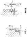
- Fig. 2A and Fig. 2B are schematic cross-sectional views illustrating molds and molding components in first and second steps in a manufacture step.
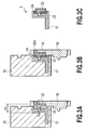
- Fig. 3A and Fig. 3B are schematic cross-sectional views illustrating the molds and the molding components in third and fourth steps.
- Fig. 3C is a cross-sectional view illustrating an ink supply member taken out from the molds.
- Fig. 4A and Fig. 4B illustrate the positional relation of molding components in the first and second steps.
- Fig. 5A and Fig. 5B illustrate the positional relation of the molding components in the third and fourth steps.
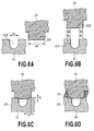
- Fig. 6A, Fig. 6B, Fig. 6C, and Fig. 6D illustrate the positional relation of the main parts of the molding components in the first, second, third, and fourth steps, respectively.
- first and second constituting components (molding components) 21 and 22 constituting the ink supply member 2 are injection-molded by resin material in a pair of molds 61 and 62.
- the first constituting component 21 is molded between a first position of the mold (first mold) 61 and a first position of the mold (second mold) 62.
- the second constituting component 22 is molded between a second position of the mold 61 and a second position of the mold 62.
- the resin material for molding them is supplied through gates 621 and 622 provided in the mold 62.
- the mold 61 can be slid in a direction of an arrow X.
- a not-shown moving mechanism moves the molds 61 and 62 to each other in a mold clamp direction and a mold open direction that are a direction orthogonal to the arrow X.
- the mold 61 is moved in the direction of the arrow X and an opposite direction.
- the first constituting component 21 includes a groove portion (ink supply path formation part) 213 forming a part of an ink supply path.
- the second constituting component 22 includes a cover portion 223 that forms the ink supply path together with the groove portion 213.
- the cover portion 223 is configured to have a width W2 wider than a width W1 of the groove portion 213 so as to block the entire opening part of the groove portion 213 (see Fig. 2B and Fig. 6A ).
- the groove portion 213 and the cover portion 223 extend within a horizontal plane.
- the ink supply path formed by the groove portion 213 and the cover portion 223 includes a part extending along the horizontal plane in the posture during the use of the print head 1.
- the first constituting component 21 includes a plurality of the groove portions 213 for forming ink supply paths corresponding to the respective six types of inks.
- the second constituting component 22 includes not-shown cover portions 223 corresponding to these groove portions 213.
- the ink supply path extends in a vertical direction in the vicinity of the connection portion 4 and in the vicinity of a connecting portion with the printing element unit 3.
- a connecting part of the portion extending in the vertical direction and the portion extending in the horizontal plane has a bent part.
- the same resin material including fillers is used as molding material of the first and second constituting components 21 and 22.
- the molds 61 and 62 are opened and then the mold 61 retaining the first constituting component 21 is slide in the direction of the arrow X.
- the first constituting component 21 is opposed to the second constituting component 22 retained by the mold 62.
- a region (first region) A1 surrounding the groove portion 213 is opposed to a region (second region) A2 surrounding the groove portion 213 and extended outside the groove portion 213 in a width direction.
- the regions A1 and A2 form the constituting components 21 and 22 by the molds 61 and 62 and are defined in a state in which the molds 61 and 62 are opened (a state before the molds 61 and 62 are mold-clamped again (second mold clamp)).
- the reference numeral A1 represents a region adjacent to the groove portion 213 that is abutted to the cover portion 223 during the second mold clamp.
- the reference numeral A2 represents a region of a tip end face of the cover portion 223 that is abutted to the constituting component 21 during the second mold clamp.
- the molds 61 and 62 are again mold-clamped as shown in Fig. 3A to allow the regions A1 and A2 to be abutted to each other as shown in Fig. 6B and Fig. 6C .
- the ink supply path 23 is formed in the groove portion 213 closed by the regions A1 and A2.
- molten resin is allowed to flow into regions at the outer side of the regions A1 and A2 to thereby form a sealing member 24.
- the molten resin forming the sealing member 24 is supplied through the gate 624 provided in the mold 62.
- the compatibility of the resin allows the first constituting component 21 to be joined with the sealing member 24 and allows the second constituting component 22 to be joined with the sealing member 24 and they are integrated to constitute the ink supply member 2.
- a part of the regions A1 and A2 also may be compatible by the heat of the molten resin.
- the molten resin is the same resin material as those of the first and second constituting components 21 and 22.
- the resin material forming the sealing member 24 may be the one compatible with the first and second constituting components 21 and 22 or may be the one different from that of these constituting components 21 and 22.
- the ink supply member 2 configured by the first and second constituting components 21 and 22 and the sealing member 24 is taken out from the molds 61 and 62 as shown in Fig. 3C .
- a position P1 in Fig. 2B is positioned at an inner face (first face) of the mold 61.
- the mold 61 is abutted, at the position P1, to a face of the first constituting component 21 positioned at an opposite side of the surrounding region A1 in a mold clamp direction (direction orthogonal to the arrow X) in the drawing.
- a distance between a position of the region A1 and the position P1 is assumed as D1.
- a position P2 in Fig. 2B is positioned at an inner face of the mold 62 (second face).
- the mold 62 is abutted, at the position P2, to a face of the second constituting component 22 positioned at an opposite side of the surrounding region A2 in the mold clamp direction.
- a distance between a position of the region A2 and the position P2 is assumed as D2.
- a distance between the positions P1 and P2 in the mold clamp direction when the molds 61 and 62 are mold-closed is assumed as D3.
- These distances D1, D2, and D3 have a relation of the following formula (1).
- the distance D3 is a distance defined depending on the shape of the ink supply member 2 (the shape of a part forming the ink supply path 23) and corresponds to the interval at which the inner faces of the molds 61 and 62 are opposed during the mold clamp.
- the distance D1 corresponds to the shape of the part of the groove portion 213 in the first constituting component 21.
- the distance D2 corresponds to the shape of the cover portion 223 in the second constituting component 22.
- the sum of the distances D1 and D2 is set to be larger than the distance D3 defined depending on the shape of the ink supply member 2.
- the regions A2 are pushed into the regions A1 (or buried into the regions A1). Then, parts in the vicinity of the region A1 and region A2 may be shaped so that only one of the region A1 side or the region A2 side is deformed when compared with the shapes at the end of the second step or both of the region A1 side and the region A2 side are deformed when compared with the shapes at the end of the second step.
- the surface of the first constituting component 21 mold-separated from the mold 62 and the surface of the second constituting component 22 mold-separated from the mold 61 have warpage in the entirety or a partial sink mark for example.
- the regions A1 and A2 as an abutted part thereof may partially include a gap.
- the subsequent fourth step of Fig. 3B there is a risk where molten resin enters the ink supply path 23 through the gap.
- the regions A2 can be pushed into the regions A1 to thereby allow the regions A1 to be securely abutted to the regions A2, thereby suppressing the molten resin from entering the ink supply path 23.
- the regions A2 are pushed into the regions A1 by a relative pushing amount Z approximately set to an amount that can absorb the variation in the flatness of the regions A1 and A2 at the completion of the second step.
- the pushing amount Z is desirably 0.03mm or more and 0.2mm or less.
- the relation between the pushing amount Z and the width W of the abutted part is desirably set so that W/Z is within a range of 1 to 30. Specifically, the relation is desirably set so as to satisfy a relation of the following formula (2). 1 ⁇ W / D 1 + D 2 ⁇ D 3 ⁇ 30
- the relation is more preferably set so that W/Z is within a range of 1.5 to 20. Specifically, the relation is desirably set so as to satisfy a relation of the following formula (3). 1.5 ⁇ W / D 1 + D 2 ⁇ D 3 ⁇ 20
- the abutted parts of the regions A1 and A2 desirably have, as shown in Fig. 6A to Fig. 6D , corners (ridge lines) of the groove portion 213 and the cover portion 223.
- corners ridge lines
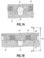
- Fig. 7A in a cross section orthogonal to the direction along which the ink supply path 23 extends as shown in Fig. 7A , only any one of the regions A1 and A2 has a plane and does not have to have a corner.
- Fig. 7A in a cross section orthogonal to the direction along which the ink supply path 23 extends as shown in Fig. 7A , only any one of the regions A1 and A2 has a plane and does not have to have a corner.
- the region A2 of the second constituting component 22 must have a sufficiently-wide width so that the region A2 is prevented from being fallen due to the pressure of the molten resin forming the sealing member 24, thus consequently increasing the widths of the abutted parts of the regions A1 and A2.
- the stress caused when the regions A1 and A2 are collapsed is reduced due to the heat of the molten resin.
- the heat is suppressed from being transmitted in a part away from the sealing member 24, thus causing the stress to remain therein.
- a configuration as shown in Fig. 6A to Fig. 6D is preferred in which the groove portion 213 and the corner of the cover portion 223 are positioned at the abutted parts of the regions A1 and A2 to reduce the width of the abutted parts of the regions A1 and A2.
- a shape of the sealing member 24 (shape of a flow path in which molten resin flows) is defined by the first constituting component 21, the second constituting component 22, and the molds 61 and 62.
- a configuration as shown in Fig. 7B also may be used in which the shape of the sealing member 24 is defined only by the first constituting component 21 and the second constituting component 22.
- the abutted parts of the regions A1 and A2 positioned along the ink supply path 23 have parts pushed into each other as in the above-described example.
- abutted parts of a region (third region) B1 and a region (fourth region) B2 defining the outer side of the molten resin may not have to have such parts pushed into each other.
- the molten resin can be more securely suppressed from entering the ink supply path 23.
- the abutted parts of the regions B1 and B2 may be pushed to each other by a pushing amount smaller than a pushing amount at which the regions A1 and A2 are pushed to each other.
- a distance between the region B1 and a position P11 of the face of the mold 61 (third face) abutted to a region at an opposite side of the region B1 in the first constituting component 21 is assumed as E1.
- a distance between the region B2 and a position P12 of the second mold face (fourth face) abutted to a region at an opposite side of the region B2 in the second constituting component 22 is assumed as E2.
- a distance between the positions P11 and P12 when the molds 61 and 62 are closed is assumed as E3.
- the first constituting component 21-side part of the ink supply path 23 is connected to the ink tank (liquid container).
- the second constituting component 22-side part of the ink supply path 23 is connected to the printing element unit 3.
- the former part is connected to the printing element unit 3 and the latter part is connected to the ink tank.
- the first constituting component 21 includes the cover portion 223 and the second constituting component 22 includes the groove portion 213.
- Fig. 8A is a perspective view illustrating the print head 1 in the second embodiment of the present invention.
- the print head 1 includes the ink supply member (housing) 2, the printing element unit 3, and the electric connection substrate 5.
- the ink supply member 2 is constituted by the first and second constituting components 21 and 22 of Fig. 8B .
- Fig. 9 is an exploded perspective view illustrating the first and second constituting components 21 and 22.
- the ink supply path 23 is bent within upper and lower vertical planes and is formed by the steps similar to that of the above-described embodiment.
- the width W and the pushing amount Z of the abutted parts of the regions A1 and A2 are set so that W/Z is within a range of 1 to 30 as in the above-described embodiment.
- a receiving face 215 is formed in the first constituting component 21 and a receiving face 225 is formed in the second constituting component 22.
- These receiving faces 215 and 225 are positioned on the same flat surface and position thereon an electric connection substrate 5.
- the components are influence by the size variation or joint accuracy of these two components.
- the third component when the third component is placed so as to be positioned on these two components, one of the two components generally has a face including a receiving face abutted to the third component and a face of the other component is generally retracted to a position free from the interference with the third component.
- the substrate 5 receives a load due to the connection to the print apparatus-side contact point.
- a risk is caused where a part at which a back face is not received by a face of the other component is deformed, which causes unstable electric connection.
- the positional relation between the first and second constituting components 22 and 23 can be set with a high accuracy to improve the dimensional accuracy of the ink supply member 2.
- the receiving face 215 at the first constituting component 22 and the receiving face 225 at the first constituting component 22 can be accurately positioned relative to each other, thus eliminating the need to retract one of the first and second constituting components 22 and 23 from the electric connection substrate 5.
- the receiving faces 215 and 225 of the first and second constituting components 22 and 23 can have thereon the electric connection substrate 5, thereby suppressing the deformation of the electric connection substrate 5.
- the outer dimension of the ink supply member 2 can be accurately set, thus reducing the limitation on the layout of components such as the electric connection substrate 5.
- This can consequently provide the cost reduction by the size reduction of the first and second constituting components 22 and 23, the size reduction of the ink supply member 2, and the size reduction of the print head 1.
- the first and second constituting components and the sealing member 24 can be formed by the same resin material, which is also preferred from the viewpoint of the relation with ink (wetting property) .
- the respective parts have substantially the same linear expansion coefficient. This can consequently reduce the influence by the expansion or contraction of the respective parts due to a temperature change.
- the present invention is not limited to the manufacture of an ink supply member provided in an inkjet print head.
- the invention can be applied to the manufacture of a liquid supply member including various liquid supply paths.
Landscapes
- Engineering & Computer Science (AREA)
- Manufacturing & Machinery (AREA)
- Mechanical Engineering (AREA)
- Particle Formation And Scattering Control In Inkjet Printers (AREA)
- Moulds For Moulding Plastics Or The Like (AREA)
- Injection Moulding Of Plastics Or The Like (AREA)
Abstract
Description
- The present invention relates to a manufacture method of a liquid supply member including therein a liquid supply path and a manufacture apparatus.
- This type of liquid supply member is provided, for example, in a liquid ejection head that can eject liquid, supplied from a liquid container, through an ejection portion. The liquid supply member includes therein a liquid supply path between the liquid container and the ejection unit. The liquid ejection head may be an inkjet print head that can eject ink, supplied from an ink tank (liquid container), through a plurality of ejection openings (ejection portion). A print head that can eject a plurality of types of inks includes an ink supply member (liquid supply member) including a plurality of ink supply paths (liquid supply paths) corresponding to the respective inks.
- Generally, the liquid supply member having a liquid supply path as described above are configured, from the viewpoint of easy manufacturing, light weight, and corrosion resistance, by the combination of a plurality of components obtained by subjecting resin material to injection molding. For example, the plurality of components are individually subjected to injection molding and are subsequently assembled by the adhesion by ultrasonic welding or adhesive material for example.
- However, when the plurality of components individually subjected to injection molding are assembled by welding or adhesion for example, the dimensional accuracy among the plurality of components may be compromised. The reason is that the dimensional accuracy of the liquid supply members after the assembly is influenced by the molding accuracy and joint accuracy of these components for example.
- The present invention provides a manufacture method and a manufacture apparatus by which a liquid supply member having a high dimensional accuracy can be manufactured while securing the shape of a liquid supply path suitable for stable liquid supply.
- The present invention in its first aspect provides a manufacture method of a liquid supply member as specified in
claims 1 to 8. - The present invention in its second aspect provides a manufacture apparatus of a liquid supply member as specified in claims 9 and 10.
- According to the present invention, first and second constituting components are injection-molded and joined within one mold. Thus, a liquid supply member having a high dimensional accuracy can be manufactured.
- Furthermore, the first and second constituting components can be joined so that the respective regions of the first and second constituting components abutted to each other are pushed to each other, thereby securely allowing these regions to be abutted to each other. For example, even when these regions include a sink mark or warpage for example, these regions can be securely abutted to each other over the entire face. This consequently allows, when molten resin is allowed to flow to the outer side of these regions, the molten resin can be suppressed from flowing to a part forming the liquid supply path, thereby securing the shape of the liquid supply path suitable for the stable liquid supply.
- Further features of the present invention will become apparent from the following description of exemplary embodiments (with reference to the attached drawings).
-
-
Fig. 1A and Fig. 1B are perspective views illustrating a print head of the first embodiment of the present invention, respectively; -
Fig. 2A and Fig. 2B are schematic cross-sectional views of the main part illustrating the print head ofFig. 1A in a manufacture stage, respectively; -
Fig. 3A, Fig. 3B, and Fig. 3C are schematic cross-sectional views of the main part illustrating the print head ofFig. 1A in the manufacture stage, respectively; -
Fig. 4A and Fig. 4B are schematic cross-sectional views of the main part illustrating the first and second constituting components of the print head ofFig. 1A in the manufacture stage, respectively; -
Fig. 5A and Fig. 5B are perspective views illustrating the first and second constituting components of the print head ofFig. 1A in the manufacture stage, respectively; -
Fig. 6A, Fig. 6B, Fig. 6C, and Fig. 6D are schematic cross-sectional views of the main part illustrating the print head ofFig. 1A in the manufacture stage, respectively; -
Fig. 7A and Fig. 7B are schematic cross-sectional views of the main part for explaining another configuration example of the print head ofFig. 1A in the manufacture stage, respectively; -
Fig. 8A and Fig. 8B are perspective views illustrating the print head in the second embodiment of the present invention, respectively; and -
Fig. 9 is an exploded perspective view illustrating the print head ofFig. 8A . - First, prior to the description of an embodiment of the present invention, the following section will describe a manufacture method of a hollow structure including therein a hollow unit that can injection-mold and join a plurality of components within a mold (die slide injection molding). The manufacture method as described above is disclosed, for example, in Japanese Patent Laid-Open No.
2002-178538 - In the manufacture method as described above, at a dislocated position within a pair of molds (a fixed-side mold and a movable-side mold), two components constituting the hollow structure (e.g., one is a component having an opening unit and the other is a component covering the opening unit) are injection-molded, respectively (primary molding), and the molds are subsequently opened. During this, one of the two components is allowed to remain in the fixed-side mold and the other is allowed to remain in the movable-side mold. Next, one of these molds is slid so that the one component remaining in the fixed-side mold and the other component remaining in the movable-side mold are opposite to one another and then these molds are closed. At this point of time, the two components are abutted to each other to form a hollow structure but are not joined. Thereafter, molten resin is allowed to flow to the abutted part (secondary molding) to adhere these components to thereby form the hollow structure.
- If a liquid supply member including therein a liquid supply path is manufactured using such a manufacture method, a plurality of components constituting the liquid supply member can be molded and joined within one mold to thereby retain the joint accuracy of a plurality of components approximately within the size of one component. However, during the secondary molding, faces of the two components abutted to each other may locally include a not-abutted part due to the influence by a sink mark or warpage for example caused when they are separated from the mold after the primary molding. When such a not-abutted part is caused, secondary molding molten resin is caused to flow through this part into a space in which the liquid supply path is formed, thus causing a risk where the shape of the liquid supply path suitable for stable liquid supply cannot be secured or the liquid supply path is blocked. In particular, in the case of an ink supply member included in an inkjet print head, ink supply paths are densely configured in order to provide a print head having a smaller size. Thus, a region (flow path) in which the secondary molding molten resin flows is also narrowed, thus requiring the pressure of the secondary molding molten resin to be increased so that the molten resin can be flowed into the narrow region between these ink supply paths. Thus, the molten resin particularly tends to flow. When the flowing of such molten resin causes a part having a different shape to be formed in the ink supply path, a risk is caused in which the growth of bubbles in the ink supply path is started from the part and the bubbles remain and ink cannot be sufficiently supplied. Such a influence is high.
- The present invention has been made based on the founding as described above.
- The following section will describe embodiments of the present invention with reference to the drawings. A liquid supply member in the following embodiment is an application example as an ink supply member included in an inkjet print head.
-
Fig. 1A and Fig. 1B are perspective views illustrating an inkjet print head (liquid ejection head) 1 including an ink supply member (liquid supply member) in this embodiment. Theprint head 1 of this example is provided in a carriage of a so-called serial scan-type inkjet print apparatus (liquid ejection apparatus). Theprint head 1 also may be configured so as to be included in a so-called full line-type inkjet print apparatus. - The
print head 1 of this example for ejecting various types of liquids such as ink includes an ink supply member (housing) 2, aprinting element unit 3, and anelectric connection substrate 5. The ink (liquid) is supplied to theprinting element unit 3 from a not-shown ink tank (liquid container) through aconnection unit 4 of theink supply member 2 and an ink supply path in the ink supply member 2 (liquid supply path) . In theprinting element unit 3, a plurality of ejection openings that can eject ink are arranged so as to form a not-shown ejection opening array. For each ejection opening, an ejection energy generation element such as an electrothermal transducing element (heater) or a piezo element is provided. In this example, sixconnection portions 4 supply inks of the total of six colors and these inks are ejected from the ejection opening array corresponding to them. Thus, theink supply member 2 includes ink supply paths providing the communication between the sixconnection portions 4 and the ejection arrays corresponding to them. The ejection opening arrays are arranged at an interval smaller than an interval at which the six connection portions corresponding to them are arranged. The ink flow paths corresponding to the six connection portions include the one having a bent shape. A not-shown print apparatus is used to drive the ejection energy generation element through anelectric connection substrate 5 to thereby eject ink through the ejection opening corresponding to it. -
Fig. 2A to Fig. 5B illustrate the manufacture method of the ink supply member. As the manufacture method thereof, a manufacture method (die slide injection molding) is basically used.Fig. 2A and Fig. 2B are schematic cross-sectional views illustrating molds and molding components in first and second steps in a manufacture step.Fig. 3A and Fig. 3B are schematic cross-sectional views illustrating the molds and the molding components in third and fourth steps.Fig. 3C is a cross-sectional view illustrating an ink supply member taken out from the molds.Fig. 4A and Fig. 4B illustrate the positional relation of molding components in the first and second steps.Fig. 5A and Fig. 5B illustrate the positional relation of the molding components in the third and fourth steps.Fig. 6A, Fig. 6B, Fig. 6C, and Fig. 6D illustrate the positional relation of the main parts of the molding components in the first, second, third, and fourth steps, respectively. - In the first step, as shown in
Fig. 2A , first and second constituting components (molding components) 21 and 22 constituting theink supply member 2 are injection-molded by resin material in a pair ofmolds first constituting component 21 is molded between a first position of the mold (first mold) 61 and a first position of the mold (second mold) 62. Thesecond constituting component 22 is molded between a second position of themold 61 and a second position of themold 62. The resin material for molding them is supplied throughgates mold 62. Themold 61 can be slid in a direction of an arrow X. A not-shown moving mechanism moves themolds mold 61 is moved in the direction of the arrow X and an opposite direction. - The
first constituting component 21 includes a groove portion (ink supply path formation part) 213 forming a part of an ink supply path. Thesecond constituting component 22 includes acover portion 223 that forms the ink supply path together with thegroove portion 213. Thecover portion 223 is configured to have a width W2 wider than a width W1 of thegroove portion 213 so as to block the entire opening part of the groove portion 213 (seeFig. 2B andFig. 6A ). - As shown in
Fig. 1A , in a posture during the use of theprint head 1 in which theprinting element unit 3 is positioned at the lower side, thegroove portion 213 and thecover portion 223 extend within a horizontal plane. Specifically, the ink supply path formed by thegroove portion 213 and thecover portion 223 includes a part extending along the horizontal plane in the posture during the use of theprint head 1. InFig. 4A , thefirst constituting component 21 includes a plurality of thegroove portions 213 for forming ink supply paths corresponding to the respective six types of inks. Thesecond constituting component 22 includes not-showncover portions 223 corresponding to thesegroove portions 213. In the posture during the use of theprint head 1, the ink supply path extends in a vertical direction in the vicinity of theconnection portion 4 and in the vicinity of a connecting portion with theprinting element unit 3. A connecting part of the portion extending in the vertical direction and the portion extending in the horizontal plane has a bent part. In this example, as molding material of the first andsecond constituting components - In the next second step, as shown in
Fig. 2B , themolds mold 61 retaining thefirst constituting component 21 is slide in the direction of the arrow X. As shown inFig. 4B , thefirst constituting component 21 is opposed to thesecond constituting component 22 retained by themold 62. As a result, as shown inFig. 6B , a region (first region) A1 surrounding thegroove portion 213 is opposed to a region (second region) A2 surrounding thegroove portion 213 and extended outside thegroove portion 213 in a width direction. Specifically, the regions A1 and A2 form the constitutingcomponents molds molds molds groove portion 213 that is abutted to thecover portion 223 during the second mold clamp. The reference numeral A2 represents a region of a tip end face of thecover portion 223 that is abutted to theconstituting component 21 during the second mold clamp. - In the next third step, the
molds Fig. 3A to allow the regions A1 and A2 to be abutted to each other as shown inFig. 6B and Fig. 6C . As a result, theink supply path 23 is formed in thegroove portion 213 closed by the regions A1 and A2. - In the next fourth step, as shown in
Fig. 3B andFig. 6D , molten resin is allowed to flow into regions at the outer side of the regions A1 and A2 to thereby form a sealingmember 24. The molten resin forming the sealingmember 24 is supplied through thegate 624 provided in themold 62. The compatibility of the resin allows thefirst constituting component 21 to be joined with the sealingmember 24 and allows thesecond constituting component 22 to be joined with the sealingmember 24 and they are integrated to constitute theink supply member 2. During this, a part of the regions A1 and A2 also may be compatible by the heat of the molten resin. In this example, the molten resin is the same resin material as those of the first andsecond constituting components member 24 may be the one compatible with the first andsecond constituting components components ink supply member 2 configured by the first andsecond constituting components member 24 is taken out from themolds Fig. 3C . - Next, the following section will describe a relation of the regions A1 and A2.
- A position P1 in
Fig. 2B is positioned at an inner face (first face) of themold 61. Themold 61 is abutted, at the position P1, to a face of thefirst constituting component 21 positioned at an opposite side of the surrounding region A1 in a mold clamp direction (direction orthogonal to the arrow X) in the drawing. In the mold clamp direction, a distance between a position of the region A1 and the position P1 is assumed as D1. A position P2 inFig. 2B is positioned at an inner face of the mold 62 (second face). Themold 62 is abutted, at the position P2, to a face of thesecond constituting component 22 positioned at an opposite side of the surrounding region A2 in the mold clamp direction. In the mold clamp direction, a distance between a position of the region A2 and the position P2 is assumed as D2. As shown inFig. 3A , a distance between the positions P1 and P2 in the mold clamp direction when themolds 
- As shown in
Fig. 3A , the distance D3 is a distance defined depending on the shape of the ink supply member 2 (the shape of a part forming the ink supply path 23) and corresponds to the interval at which the inner faces of themolds groove portion 213 in thefirst constituting component 21. The distance D2 corresponds to the shape of thecover portion 223 in thesecond constituting component 22. The sum of the distances D1 and D2 is set to be larger than the distance D3 defined depending on the shape of theink supply member 2. Thus, when the third step is completed, as shown inFig. 6C , the regions A2 are pushed into the regions A1 (or buried into the regions A1). Then, parts in the vicinity of the region A1 and region A2 may be shaped so that only one of the region A1 side or the region A2 side is deformed when compared with the shapes at the end of the second step or both of the region A1 side and the region A2 side are deformed when compared with the shapes at the end of the second step. - At the end of the second step, the surface of the
first constituting component 21 mold-separated from themold 62 and the surface of thesecond constituting component 22 mold-separated from themold 61 have warpage in the entirety or a partial sink mark for example. This prevents the regions A1 and A2 from having a completely-flat surface. Thus, when the regions A1 and A2 are abutted so as to merely touch each other (in the case of D1+D2=D3), in the subsequent third step ofFig. 3A , the regions A1 and A2 as an abutted part thereof may partially include a gap. In such a case, as described above, in the subsequent fourth step ofFig. 3B , there is a risk where molten resin enters theink supply path 23 through the gap. - In this example, as shown in
Fig. 6C , the regions A2 can be pushed into the regions A1 to thereby allow the regions A1 to be securely abutted to the regions A2, thereby suppressing the molten resin from entering theink supply path 23. The regions A2 are pushed into the regions A1 by a relative pushing amount Z approximately set to an amount that can absorb the variation in the flatness of the regions A1 and A2 at the completion of the second step. When the pushing amount Z is excessively high on the other hand, thegroove portion 213 and thecover portion 223 are significantly deformed, causing a risk where the shapes of theink supply path 23 and the other parts are influenced. The pushing amount Z is desirably 0.03mm or more and 0.2mm or less. - When parts at which the regions A1 and A2 are abutted to each other have a width W (
Fig. 6C ) to which the pushing amount Z is excessively high, and when themolds ink supply path 23 includes a part having a different shape. When the abutted parts have an excessively-small width W and when the compatibility is provided due the heat of the molten resin, the shapes of the ends of thegroove portion 213 and thecover portion 223 are broken, causing a risk where the molten resin flows through the broken part into theink supply path 23. When these abutted parts have an excessively-wide width W on the other hand, the mold clamping forces of themolds 
- In the
ink supply member 2 of theprint head 1, as described above, the plurality ofink supply paths 23 are densely formed. Thus, in the fourth step ofFig. 3B , the molten resin forming the sealingmember 24 tends to be injected at a higher pressure. Furthermore, since theink supply path 23 is minute, if the molten resin forming the sealingmember 24 enters theink supply path 23, the ink supply may be hindered with a high probability. From these viewpoints, in theink supply member 2 of theprint head 1, the relation is more preferably set so that W/Z is within a range of 1.5 to 20. Specifically, the relation is desirably set so as to satisfy a relation of the following formula (3).
- The abutted parts of the regions A1 and A2 desirably have, as shown in
Fig. 6A to Fig. 6D , corners (ridge lines) of thegroove portion 213 and thecover portion 223. In the present invention, in a cross section orthogonal to the direction along which theink supply path 23 extends as shown inFig. 7A , only any one of the regions A1 and A2 has a plane and does not have to have a corner. However, in the case ofFig. 7A , the region A2 of thesecond constituting component 22 must have a sufficiently-wide width so that the region A2 is prevented from being fallen due to the pressure of the molten resin forming the sealingmember 24, thus consequently increasing the widths of the abutted parts of the regions A1 and A2. At these abutted parts, in a part in the vicinity of the sealingmember 24, the stress caused when the regions A1 and A2 are collapsed is reduced due to the heat of the molten resin. However, the heat is suppressed from being transmitted in a part away from the sealingmember 24, thus causing the stress to remain therein. Thus, a configuration as shown inFig. 6A to Fig. 6D is preferred in which thegroove portion 213 and the corner of thecover portion 223 are positioned at the abutted parts of the regions A1 and A2 to reduce the width of the abutted parts of the regions A1 and A2. - In this example, as shown in
Fig. 3A to Fig. 3C , a shape of the sealing member 24 (shape of a flow path in which molten resin flows) is defined by thefirst constituting component 21, thesecond constituting component 22, and themolds Fig. 7B also may be used in which the shape of the sealingmember 24 is defined only by thefirst constituting component 21 and thesecond constituting component 22. In this case, the abutted parts of the regions A1 and A2 positioned along theink supply path 23 have parts pushed into each other as in the above-described example. On the other hand, abutted parts of a region (third region) B1 and a region (fourth region) B2 defining the outer side of the molten resin may not have to have such parts pushed into each other. As described above, by pushing the abutted parts of the regions A1 and A2 to each other, the molten resin can be more securely suppressed from entering theink supply path 23. Furthermore, the abutted parts of the regions B1 and B2 may be pushed to each other by a pushing amount smaller than a pushing amount at which the regions A1 and A2 are pushed to each other. - Specifically, in
Fig. 7B , a distance between the region B1 and a position P11 of the face of the mold 61 (third face) abutted to a region at an opposite side of the region B1 in thefirst constituting component 21 is assumed as E1. A distance between the region B2 and a position P12 of the second mold face (fourth face) abutted to a region at an opposite side of the region B2 in thesecond constituting component 22 is assumed as E2. A distance between the positions P11 and P12 when themolds 
- In this example, the first constituting component 21-side part of the
ink supply path 23 is connected to the ink tank (liquid container). The second constituting component 22-side part of theink supply path 23 is connected to theprinting element unit 3. However, contrary to this, another configuration may be used in which the former part is connected to theprinting element unit 3 and the latter part is connected to the ink tank. Another configuration also may be used in which thefirst constituting component 21 includes thecover portion 223 and thesecond constituting component 22 includes thegroove portion 213. -
Fig. 8A is a perspective view illustrating theprint head 1 in the second embodiment of the present invention. Similarly to the above-described embodiment, theprint head 1 includes the ink supply member (housing) 2, theprinting element unit 3, and theelectric connection substrate 5. Theink supply member 2 is constituted by the first andsecond constituting components Fig. 8B .Fig. 9 is an exploded perspective view illustrating the first andsecond constituting components ink supply path 23 is bent within upper and lower vertical planes and is formed by the steps similar to that of the above-described embodiment. The width W and the pushing amount Z of the abutted parts of the regions A1 and A2 are set so that W/Z is within a range of 1 to 30 as in the above-described embodiment. - In this example, as a face receiving the
electric connection substrate 5 positioned at a fixed position, a receivingface 215 is formed in thefirst constituting component 21 and a receivingface 225 is formed in thesecond constituting component 22. These receiving faces 215 and 225 are positioned on the same flat surface and position thereon anelectric connection substrate 5. - Generally, when two components are joined by adhesion or welding for example, the components are influence by the size variation or joint accuracy of these two components. Thus, when the third component is placed so as to be positioned on these two components, one of the two components generally has a face including a receiving face abutted to the third component and a face of the other component is generally retracted to a position free from the interference with the third component. During the use of the
electric connection substrate 5, thesubstrate 5 receives a load due to the connection to the print apparatus-side contact point. Thus, a risk is caused where a part at which a back face is not received by a face of the other component is deformed, which causes unstable electric connection. - In contrast with this, in this example, as described above, the positional relation between the first and
second constituting components ink supply member 2. Thus, the receivingface 215 at thefirst constituting component 22 and the receivingface 225 at thefirst constituting component 22 can be accurately positioned relative to each other, thus eliminating the need to retract one of the first andsecond constituting components electric connection substrate 5. Thus, the receiving faces 215 and 225 of the first andsecond constituting components electric connection substrate 5, thereby suppressing the deformation of theelectric connection substrate 5. As described above, while the shape of theink supply path 23 through which stable ink supply can be provided is being secured, the outer dimension of theink supply member 2 can be accurately set, thus reducing the limitation on the layout of components such as theelectric connection substrate 5. This can consequently provide the cost reduction by the size reduction of the first andsecond constituting components ink supply member 2, and the size reduction of theprint head 1. Furthermore, the first and second constituting components and the sealingmember 24 can be formed by the same resin material, which is also preferred from the viewpoint of the relation with ink (wetting property) . Furthermore, when the former and the latter are formed by the same resin material, the respective parts have substantially the same linear expansion coefficient. This can consequently reduce the influence by the expansion or contraction of the respective parts due to a temperature change. - The present invention is not limited to the manufacture of an ink supply member provided in an inkjet print head. The invention can be applied to the manufacture of a liquid supply member including various liquid supply paths.
- While the present invention has been described with reference to exemplary embodiments, it is to be understood that the invention is not limited to the disclosed exemplary embodiments. The scope of the following claims is to be accorded the broadest interpretation so as to encompass all such modifications and equivalent structures and functions.
Claims (10)
- A manufacture method of a liquid supply member (2) configured by a plurality of constituting components including first and second constituting components (21, 22) for forming a liquid supply path (23) between the first constituting component (21) and the second constituting component (22), comprising:a first step of injection-molding the first constituting component (21) between a first position of a first mold (61) and a first position of a second mold (62) and inj ection-molding the second constituting component (22) between a second position of the first mold (61) and a second position of the second mold (62);a second step of opening the first mold (61) and the second mold (62) so that the first position of the first mold (61) has the first constituting component (21) and the second position of the second mold (62) has the second constituting component (22) to subsequently move the first mold (61) relative to the second mold (62) so that the first constituting component (21) is opposed to the second constituting component (22);a third step of closing the first mold (61) and the second mold (62) so that a first region surrounding a part in which the liquid supply path (23) is formed in the first constituting component (21) and a second region surrounding a part in which the liquid supply path (23) is formed in the second constituting component (22) are abutted to each other; anda fourth step of allowing molten resin (24) to flow to the outer side of the first and second regions,wherein in the third step, one of the first region and the second region is pushed to the other when the first mold (61) and the second mold (62) are closed.
- The manufacture method of the liquid supply member according to claim 1, wherein:in a state prior to the closure of the first mold and the second mold in the third step, a distance between the first region and a first face of the first mold abutted to a region at an opposite face of the first region in the first constituting component is assumed as D1, and a distance between the second region and a second face of the second mold abutted to a region at an opposite side of the second region in the second constituting component is assumed as D2,in a state where the first mold and the second mold are closed in the third step, a distance between the first face and the second face is assumed as D3, andthe distances D1, D2, and D3 have a relation of D1+D2>D3.
- The manufacture method of the liquid supply member according to claim 2, wherein:in the third step, a width W of an abutted part of the first and second regions in a width direction of the liquid supply path and the distances D1, D2, and D3 have a relation of 1≤W / (D1+D2-D3) ≤30.
- The manufacture method of the liquid supply member according to claim 2, wherein:in the third step, a width W of an abutted part of the first and second regions in a width direction of the liquid supply path and the distances D1, D2, and D3 have a relation of 1.5≤W/ (D1+D2-D3)≤20.
- The manufacture method of the liquid supply member according to any one of claims 1 to 4, wherein:at least one of the first region and the second region includes a corner positioned at an abutted part of the first and second regions.
- The manufacture method of the liquid supply member according to any one of claims 1 to 5, wherein:the first constituting component and the second constituting component respectively include a third region and a fourth region abutted to each other so as to define, when the first mold and the second mold are closed in the third step, an outer shape of the molten resin flown in the fourth step.
- The manufacture method of the liquid supply member according to claim 6, wherein:in a state prior to the closure of the first mold and the second mold in the third step, a distance between the third region and a third face of the first mold abutted to a region at an opposite side of the third region in the first constituting component is assumed as E1, and a distance between the fourth region and a fourth face of the second mold abutted to a region at an opposite side of the fourth region in the second constituting component is assumed as E2,in a state where the first mold and the second mold are closed in the third step, a distance between the third face and the fourth face is assumed as E3, andthe distances E1, E2, and E3 and the distances D1, D2, and D3 have a relation of D1+D2-D3>E1+E2-E3.
- The manufacture method of the liquid supply member according to any one of claims 1 to 7, wherein:the plurality of constituting components includes a third constituting component,the third constituting component is attached to be abutted to a first receiving face formed on the first constituting component and a second receiving face formed on the second constituting component, respectively.
- A manufacture apparatus of a liquid supply member configured by a plurality of constituting components including first and second constituting components for forming a liquid supply path between the first constituting component and the second constituting component, comprising:a first mold and a first position of a second mold,a molding unit of injection-molding the first constituting component between a first position of the first mold and a first position of the second mold and injection-molding the second constituting component between a second position of the first mold and a second position of the second mold;a moving unit of opening the first mold and the second mold so that the first position of the first mold has the first constituting component and the second position of the second mold has the second constituting component to subsequently move the first mold relative to the second mold so that the first constituting component is opposed to the second constituting component;a mold-closing unit of closing the first mold and the second mold so that a first region surrounding a part in which the liquid supply path is formed in the first constituting component and a second region surrounding a part in which the liquid supply path is formed in the second constituting component are abutted to each other; anda unit of allowing molten resin to flow to the outer side of the first and second regions,wherein the mold-closing unit pushes one of the first region and the second region to the other when the first mold and the second mold are closed.
- The manufacture apparatus of the liquid supply member according to claim 9, wherein:in a state after the first and second constituting components are inj ection-molded and before the first and second molds are closed, a distance between the first region and a first face of the first mold abutted to a region at an opposite side of the first region in the first constituting component is assumed as D1, a distance between the second region and a second face of the second mold abutted to a region at an opposite side of the second region in the second constituting component is assumed as D2,in a state after the first and second constituting components are inj ection-molded and while the first and second molds are being closed, a distance between the first face and the second face in a direction along which the first mold and the second mold are closed is assumed as D3, andthe molding unit injection-molds the first and second constituting components so that a relation of D1+D2>D3 is established.
Applications Claiming Priority (2)
| Application Number | Priority Date | Filing Date | Title |
|---|---|---|---|
| JP2015105103 | 2015-05-25 | ||
| JP2016061821A JP6702772B2 (en) | 2015-05-25 | 2016-03-25 | Liquid supply member manufacturing method and manufacturing apparatus |
Publications (2)
| Publication Number | Publication Date |
|---|---|
| EP3098076A1 true EP3098076A1 (en) | 2016-11-30 |
| EP3098076B1 EP3098076B1 (en) | 2018-01-31 |
Family
ID=55966965
Family Applications (1)
| Application Number | Title | Priority Date | Filing Date |
|---|---|---|---|
| EP16000983.3A Active EP3098076B1 (en) | 2015-05-25 | 2016-05-02 | Manufacture method of liquid supply member and manufacture apparatus |
Country Status (4)
| Country | Link |
|---|---|
| US (1) | US10300643B2 (en) |
| EP (1) | EP3098076B1 (en) |
| KR (1) | KR102011555B1 (en) |
| CN (1) | CN106183427B (en) |
Cited By (1)
| Publication number | Priority date | Publication date | Assignee | Title |
|---|---|---|---|---|
| EP4566789A1 (en) * | 2023-12-08 | 2025-06-11 | Canon Kabushiki Kaisha | Article manufacturing method |
Families Citing this family (9)
| Publication number | Priority date | Publication date | Assignee | Title |
|---|---|---|---|---|
| JP6590528B2 (en) | 2015-05-25 | 2019-10-16 | キヤノン株式会社 | Method for manufacturing liquid supply member |
| JP6701008B2 (en) | 2016-06-28 | 2020-05-27 | キヤノン株式会社 | Resin molding method |
| JP6794156B2 (en) | 2016-06-30 | 2020-12-02 | キヤノン株式会社 | Resin molding method |
| JP6400054B2 (en) | 2016-07-29 | 2018-10-03 | キヤノン株式会社 | Liquid supply member and method for manufacturing liquid supply member |
| JP6338623B2 (en) | 2016-07-29 | 2018-06-06 | キヤノン株式会社 | Method for manufacturing liquid supply member |
| JP6869703B2 (en) | 2016-11-24 | 2021-05-12 | キヤノン株式会社 | Manufacturing method of liquid discharge head |
| JP6768467B2 (en) * | 2016-11-24 | 2020-10-14 | キヤノン株式会社 | Manufacturing method of liquid discharge head |
| JP6877965B2 (en) | 2016-11-24 | 2021-05-26 | キヤノン株式会社 | Manufacturing method of liquid supply unit |
| JP7150478B2 (en) * | 2018-05-29 | 2022-10-11 | キヤノン株式会社 | LIQUID EJECTION HEAD AND MANUFACTURING METHOD THEREOF |
Citations (5)
| Publication number | Priority date | Publication date | Assignee | Title |
|---|---|---|---|---|
| JPS6287315A (en) * | 1985-10-15 | 1987-04-21 | Japan Steel Works Ltd:The | Molding of hollow molded part and mold used therefor |
| US5969738A (en) * | 1995-12-28 | 1999-10-19 | Fuji Xerox Co., Ltd. | Ink jet printer and ink jet recording unit |
| JP2002178538A (en) | 2000-12-13 | 2002-06-26 | Takagi Seiko Corp | Method for manufacturing ink control aggregate |
| US20100171798A1 (en) * | 2009-01-07 | 2010-07-08 | Canon Kabushiki Kaisha | Liquid jet recording head and manufacturing method thereof |
| US20120293588A1 (en) * | 2011-05-16 | 2012-11-22 | Canon Kabushiki Kaisha | Flow passage assembly and method for manufacturing flow passage assembly, inkjet recording head, and recording apparatus |
Family Cites Families (9)
| Publication number | Priority date | Publication date | Assignee | Title |
|---|---|---|---|---|
| JP3609038B2 (en) | 2001-05-21 | 2005-01-12 | 株式会社日本製鋼所 | Three-layer laminate molding method and molding die |
| JP5884302B2 (en) | 2011-06-06 | 2016-03-15 | セイコーエプソン株式会社 | INJECTION MOLDING METHOD, INJECTION MOLDED ARTICLE, INK TANK, RECORDING DEVICE AND INJECTION MOLD |
| JP6590527B2 (en) | 2015-05-25 | 2019-10-16 | キヤノン株式会社 | Method for manufacturing liquid discharge head |
| JP6521740B2 (en) | 2015-05-25 | 2019-05-29 | キヤノン株式会社 | Method of manufacturing liquid discharge head |
| US9931850B2 (en) | 2015-05-25 | 2018-04-03 | Canon Kabushiki Kaisha | Manufacture method of liquid supply member, manufacture apparatus, and liquid supply member |
| JP6525728B2 (en) | 2015-05-25 | 2019-06-05 | キヤノン株式会社 | Method of manufacturing liquid supply member |
| JP6590528B2 (en) | 2015-05-25 | 2019-10-16 | キヤノン株式会社 | Method for manufacturing liquid supply member |
| US9764554B2 (en) | 2015-05-25 | 2017-09-19 | Canon Kabushiki Kaisha | Method for manufacturing molded member and liquid ejecting head, liquid ejecting head, and mold |
| JP6525729B2 (en) | 2015-05-25 | 2019-06-05 | キヤノン株式会社 | Molded part, method of manufacturing molded part, and mold |
-
2016
- 2016-05-02 EP EP16000983.3A patent/EP3098076B1/en active Active
- 2016-05-17 KR KR1020160059942A patent/KR102011555B1/en active Active
- 2016-05-18 US US15/157,909 patent/US10300643B2/en active Active
- 2016-05-24 CN CN201610349530.6A patent/CN106183427B/en active Active
Patent Citations (5)
| Publication number | Priority date | Publication date | Assignee | Title |
|---|---|---|---|---|
| JPS6287315A (en) * | 1985-10-15 | 1987-04-21 | Japan Steel Works Ltd:The | Molding of hollow molded part and mold used therefor |
| US5969738A (en) * | 1995-12-28 | 1999-10-19 | Fuji Xerox Co., Ltd. | Ink jet printer and ink jet recording unit |
| JP2002178538A (en) | 2000-12-13 | 2002-06-26 | Takagi Seiko Corp | Method for manufacturing ink control aggregate |
| US20100171798A1 (en) * | 2009-01-07 | 2010-07-08 | Canon Kabushiki Kaisha | Liquid jet recording head and manufacturing method thereof |
| US20120293588A1 (en) * | 2011-05-16 | 2012-11-22 | Canon Kabushiki Kaisha | Flow passage assembly and method for manufacturing flow passage assembly, inkjet recording head, and recording apparatus |
Cited By (1)
| Publication number | Priority date | Publication date | Assignee | Title |
|---|---|---|---|---|
| EP4566789A1 (en) * | 2023-12-08 | 2025-06-11 | Canon Kabushiki Kaisha | Article manufacturing method |
Also Published As
| Publication number | Publication date |
|---|---|
| CN106183427A (en) | 2016-12-07 |
| KR20160138346A (en) | 2016-12-05 |
| US20160346976A1 (en) | 2016-12-01 |
| KR102011555B1 (en) | 2019-08-16 |
| EP3098076B1 (en) | 2018-01-31 |
| US10300643B2 (en) | 2019-05-28 |
| CN106183427B (en) | 2018-06-22 |
Similar Documents
| Publication | Publication Date | Title |
|---|---|---|
| EP3098076B1 (en) | Manufacture method of liquid supply member and manufacture apparatus | |
| KR102010121B1 (en) | Method for manufacturing liquid-ejecting head | |
| US9931850B2 (en) | Manufacture method of liquid supply member, manufacture apparatus, and liquid supply member | |
| US10906221B2 (en) | Manufacturing method of liquid supply member | |
| US9764554B2 (en) | Method for manufacturing molded member and liquid ejecting head, liquid ejecting head, and mold | |
| US10434694B2 (en) | Resin molding method | |
| US10081185B2 (en) | Liquid ejection head, liquid ejection apparatus, flow path member, and method for manufacturing liquid ejection head | |
| US10828812B2 (en) | Molded part, manufacturing method of molded part and mold | |
| CN110539561B (en) | Liquid ejection head and method of manufacturing the same | |
| US10926441B2 (en) | Liquid supply member and manufacturing method of liquid supply member | |
| US11020887B2 (en) | Resin molding method | |
| US8025382B2 (en) | Ink jet head cartridge, print head, ink container, and method for manufacturing ink jet head cartridge | |
| CN110154538B (en) | Method and apparatus for manufacturing liquid supply member, and liquid ejection head | |
| JP6702772B2 (en) | Liquid supply member manufacturing method and manufacturing apparatus | |
| JP6736323B2 (en) | Liquid supply member manufacturing method, manufacturing apparatus, and liquid supply member | |
| US7810905B2 (en) | Printing element substrate supporting member, manufacture method of printing element substrate supporting member, and ink jet printing head | |
| US11685089B2 (en) | Manufacturing method of liquid ejection head | |
| JP2000334957A (en) | Liquid jet recording head and method of manufacturing the same |
Legal Events
| Date | Code | Title | Description |
|---|---|---|---|
| PUAI | Public reference made under article 153(3) epc to a published international application that has entered the european phase |
Free format text: ORIGINAL CODE: 0009012 |
|
| AK | Designated contracting states |
Kind code of ref document: A1 Designated state(s): AL AT BE BG CH CY CZ DE DK EE ES FI FR GB GR HR HU IE IS IT LI LT LU LV MC MK MT NL NO PL PT RO RS SE SI SK SM TR |
|
| AX | Request for extension of the european patent |
Extension state: BA ME |
|
| 17P | Request for examination filed |
Effective date: 20170530 |
|
| RBV | Designated contracting states (corrected) |
Designated state(s): AL AT BE BG CH CY CZ DE DK EE ES FI FR GB GR HR HU IE IS IT LI LT LU LV MC MK MT NL NO PL PT RO RS SE SI SK SM TR |
|
| GRAP | Despatch of communication of intention to grant a patent |
Free format text: ORIGINAL CODE: EPIDOSNIGR1 |
|
| RAP1 | Party data changed (applicant data changed or rights of an application transferred) |
Owner name: CANON KABUSHIKI KAISHA |
|
| RIN1 | Information on inventor provided before grant (corrected) |
Inventor name: IWANO, TAKUYA Inventor name: KIMURA, SATOSHI Inventor name: TODA, KYOSUKE Inventor name: TSUJIUCHI, NAOKO Inventor name: UMEYAMA, MIKIYA Inventor name: AMMA, HIROMASA Inventor name: OIKAWA, SATOSHI Inventor name: YAMAGUCHI, YUKUO Inventor name: IIJIMA, YASUSHI |
|
| INTG | Intention to grant announced |
Effective date: 20170821 |
|
| GRAS | Grant fee paid |
Free format text: ORIGINAL CODE: EPIDOSNIGR3 |
|
| GRAA | (expected) grant |
Free format text: ORIGINAL CODE: 0009210 |
|
| AK | Designated contracting states |
Kind code of ref document: B1 Designated state(s): AL AT BE BG CH CY CZ DE DK EE ES FI FR GB GR HR HU IE IS IT LI LT LU LV MC MK MT NL NO PL PT RO RS SE SI SK SM TR |
|
| REG | Reference to a national code |
Ref country code: GB Ref legal event code: FG4D Ref country code: CH Ref legal event code: EP |
|
| REG | Reference to a national code |
Ref country code: AT Ref legal event code: REF Ref document number: 966976 Country of ref document: AT Kind code of ref document: T Effective date: 20180215 |
|
| REG | Reference to a national code |
Ref country code: IE Ref legal event code: FG4D |
|
| REG | Reference to a national code |
Ref country code: DE Ref legal event code: R096 Ref document number: 602016001461 Country of ref document: DE |
|
| REG | Reference to a national code |
Ref country code: FR Ref legal event code: PLFP Year of fee payment: 3 |
|
| REG | Reference to a national code |
Ref country code: NL Ref legal event code: MP Effective date: 20180131 |
|
| REG | Reference to a national code |
Ref country code: LT Ref legal event code: MG4D |
|
| REG | Reference to a national code |
Ref country code: AT Ref legal event code: MK05 Ref document number: 966976 Country of ref document: AT Kind code of ref document: T Effective date: 20180131 |
|
| PG25 | Lapsed in a contracting state [announced via postgrant information from national office to epo] |
Ref country code: LT Free format text: LAPSE BECAUSE OF FAILURE TO SUBMIT A TRANSLATION OF THE DESCRIPTION OR TO PAY THE FEE WITHIN THE PRESCRIBED TIME-LIMIT Effective date: 20180131 Ref country code: NL Free format text: LAPSE BECAUSE OF FAILURE TO SUBMIT A TRANSLATION OF THE DESCRIPTION OR TO PAY THE FEE WITHIN THE PRESCRIBED TIME-LIMIT Effective date: 20180131 Ref country code: HR Free format text: LAPSE BECAUSE OF FAILURE TO SUBMIT A TRANSLATION OF THE DESCRIPTION OR TO PAY THE FEE WITHIN THE PRESCRIBED TIME-LIMIT Effective date: 20180131 Ref country code: ES Free format text: LAPSE BECAUSE OF FAILURE TO SUBMIT A TRANSLATION OF THE DESCRIPTION OR TO PAY THE FEE WITHIN THE PRESCRIBED TIME-LIMIT Effective date: 20180131 Ref country code: FI Free format text: LAPSE BECAUSE OF FAILURE TO SUBMIT A TRANSLATION OF THE DESCRIPTION OR TO PAY THE FEE WITHIN THE PRESCRIBED TIME-LIMIT Effective date: 20180131 Ref country code: NO Free format text: LAPSE BECAUSE OF FAILURE TO SUBMIT A TRANSLATION OF THE DESCRIPTION OR TO PAY THE FEE WITHIN THE PRESCRIBED TIME-LIMIT Effective date: 20180430 |
|
| PG25 | Lapsed in a contracting state [announced via postgrant information from national office to epo] |
Ref country code: AT Free format text: LAPSE BECAUSE OF FAILURE TO SUBMIT A TRANSLATION OF THE DESCRIPTION OR TO PAY THE FEE WITHIN THE PRESCRIBED TIME-LIMIT Effective date: 20180131 Ref country code: RS Free format text: LAPSE BECAUSE OF FAILURE TO SUBMIT A TRANSLATION OF THE DESCRIPTION OR TO PAY THE FEE WITHIN THE PRESCRIBED TIME-LIMIT Effective date: 20180131 Ref country code: PL Free format text: LAPSE BECAUSE OF FAILURE TO SUBMIT A TRANSLATION OF THE DESCRIPTION OR TO PAY THE FEE WITHIN THE PRESCRIBED TIME-LIMIT Effective date: 20180131 Ref country code: GR Free format text: LAPSE BECAUSE OF FAILURE TO SUBMIT A TRANSLATION OF THE DESCRIPTION OR TO PAY THE FEE WITHIN THE PRESCRIBED TIME-LIMIT Effective date: 20180501 Ref country code: BG Free format text: LAPSE BECAUSE OF FAILURE TO SUBMIT A TRANSLATION OF THE DESCRIPTION OR TO PAY THE FEE WITHIN THE PRESCRIBED TIME-LIMIT Effective date: 20180430 Ref country code: SE Free format text: LAPSE BECAUSE OF FAILURE TO SUBMIT A TRANSLATION OF THE DESCRIPTION OR TO PAY THE FEE WITHIN THE PRESCRIBED TIME-LIMIT Effective date: 20180131 Ref country code: IS Free format text: LAPSE BECAUSE OF FAILURE TO SUBMIT A TRANSLATION OF THE DESCRIPTION OR TO PAY THE FEE WITHIN THE PRESCRIBED TIME-LIMIT Effective date: 20180531 Ref country code: LV Free format text: LAPSE BECAUSE OF FAILURE TO SUBMIT A TRANSLATION OF THE DESCRIPTION OR TO PAY THE FEE WITHIN THE PRESCRIBED TIME-LIMIT Effective date: 20180131 |
|
| PG25 | Lapsed in a contracting state [announced via postgrant information from national office to epo] |
Ref country code: AL Free format text: LAPSE BECAUSE OF FAILURE TO SUBMIT A TRANSLATION OF THE DESCRIPTION OR TO PAY THE FEE WITHIN THE PRESCRIBED TIME-LIMIT Effective date: 20180131 Ref country code: EE Free format text: LAPSE BECAUSE OF FAILURE TO SUBMIT A TRANSLATION OF THE DESCRIPTION OR TO PAY THE FEE WITHIN THE PRESCRIBED TIME-LIMIT Effective date: 20180131 |
|
| REG | Reference to a national code |
Ref country code: DE Ref legal event code: R097 Ref document number: 602016001461 Country of ref document: DE |
|
| PG25 | Lapsed in a contracting state [announced via postgrant information from national office to epo] |
Ref country code: SK Free format text: LAPSE BECAUSE OF FAILURE TO SUBMIT A TRANSLATION OF THE DESCRIPTION OR TO PAY THE FEE WITHIN THE PRESCRIBED TIME-LIMIT Effective date: 20180131 Ref country code: DK Free format text: LAPSE BECAUSE OF FAILURE TO SUBMIT A TRANSLATION OF THE DESCRIPTION OR TO PAY THE FEE WITHIN THE PRESCRIBED TIME-LIMIT Effective date: 20180131 Ref country code: SM Free format text: LAPSE BECAUSE OF FAILURE TO SUBMIT A TRANSLATION OF THE DESCRIPTION OR TO PAY THE FEE WITHIN THE PRESCRIBED TIME-LIMIT Effective date: 20180131 Ref country code: CZ Free format text: LAPSE BECAUSE OF FAILURE TO SUBMIT A TRANSLATION OF THE DESCRIPTION OR TO PAY THE FEE WITHIN THE PRESCRIBED TIME-LIMIT Effective date: 20180131 |
|
| PLBE | No opposition filed within time limit |
Free format text: ORIGINAL CODE: 0009261 |
|
| STAA | Information on the status of an ep patent application or granted ep patent |
Free format text: STATUS: NO OPPOSITION FILED WITHIN TIME LIMIT |
|
| 26N | No opposition filed |
Effective date: 20181102 |
|
| REG | Reference to a national code |
Ref country code: BE Ref legal event code: MM Effective date: 20180531 |
|
| PG25 | Lapsed in a contracting state [announced via postgrant information from national office to epo] |
Ref country code: MC Free format text: LAPSE BECAUSE OF FAILURE TO SUBMIT A TRANSLATION OF THE DESCRIPTION OR TO PAY THE FEE WITHIN THE PRESCRIBED TIME-LIMIT Effective date: 20180131 |
|
| REG | Reference to a national code |
Ref country code: IE Ref legal event code: MM4A |
|
| PG25 | Lapsed in a contracting state [announced via postgrant information from national office to epo] |
Ref country code: SI Free format text: LAPSE BECAUSE OF FAILURE TO SUBMIT A TRANSLATION OF THE DESCRIPTION OR TO PAY THE FEE WITHIN THE PRESCRIBED TIME-LIMIT Effective date: 20180131 |
|
| PG25 | Lapsed in a contracting state [announced via postgrant information from national office to epo] |
Ref country code: LU Free format text: LAPSE BECAUSE OF NON-PAYMENT OF DUE FEES Effective date: 20180502 |
|
| PG25 | Lapsed in a contracting state [announced via postgrant information from national office to epo] |
Ref country code: IE Free format text: LAPSE BECAUSE OF NON-PAYMENT OF DUE FEES Effective date: 20180502 |
|
| PG25 | Lapsed in a contracting state [announced via postgrant information from national office to epo] |
Ref country code: BE Free format text: LAPSE BECAUSE OF NON-PAYMENT OF DUE FEES Effective date: 20180531 |
|
| REG | Reference to a national code |
Ref country code: CH Ref legal event code: PL |
|
| PG25 | Lapsed in a contracting state [announced via postgrant information from national office to epo] |
Ref country code: LI Free format text: LAPSE BECAUSE OF NON-PAYMENT OF DUE FEES Effective date: 20190531 Ref country code: CH Free format text: LAPSE BECAUSE OF NON-PAYMENT OF DUE FEES Effective date: 20190531 Ref country code: MT Free format text: LAPSE BECAUSE OF NON-PAYMENT OF DUE FEES Effective date: 20180502 |
|
| PG25 | Lapsed in a contracting state [announced via postgrant information from national office to epo] |
Ref country code: TR Free format text: LAPSE BECAUSE OF FAILURE TO SUBMIT A TRANSLATION OF THE DESCRIPTION OR TO PAY THE FEE WITHIN THE PRESCRIBED TIME-LIMIT Effective date: 20180131 |
|
| PG25 | Lapsed in a contracting state [announced via postgrant information from national office to epo] |
Ref country code: PT Free format text: LAPSE BECAUSE OF FAILURE TO SUBMIT A TRANSLATION OF THE DESCRIPTION OR TO PAY THE FEE WITHIN THE PRESCRIBED TIME-LIMIT Effective date: 20180131 |
|
| PG25 | Lapsed in a contracting state [announced via postgrant information from national office to epo] |
Ref country code: MK Free format text: LAPSE BECAUSE OF NON-PAYMENT OF DUE FEES Effective date: 20180131 Ref country code: CY Free format text: LAPSE BECAUSE OF FAILURE TO SUBMIT A TRANSLATION OF THE DESCRIPTION OR TO PAY THE FEE WITHIN THE PRESCRIBED TIME-LIMIT Effective date: 20180131 Ref country code: RO Free format text: LAPSE BECAUSE OF FAILURE TO SUBMIT A TRANSLATION OF THE DESCRIPTION OR TO PAY THE FEE WITHIN THE PRESCRIBED TIME-LIMIT Effective date: 20180131 Ref country code: HU Free format text: LAPSE BECAUSE OF FAILURE TO SUBMIT A TRANSLATION OF THE DESCRIPTION OR TO PAY THE FEE WITHIN THE PRESCRIBED TIME-LIMIT; INVALID AB INITIO Effective date: 20160502 |
|
| PGFP | Annual fee paid to national office [announced via postgrant information from national office to epo] |
Ref country code: DE Payment date: 20250423 Year of fee payment: 10 |
|
| PGFP | Annual fee paid to national office [announced via postgrant information from national office to epo] |
Ref country code: IT Payment date: 20250423 Year of fee payment: 10 |
|
| PGFP | Annual fee paid to national office [announced via postgrant information from national office to epo] |
Ref country code: FR Payment date: 20250423 Year of fee payment: 10 |
|
| PGFP | Annual fee paid to national office [announced via postgrant information from national office to epo] |
Ref country code: GB Payment date: 20260317 Year of fee payment: 11 |