EP3098054A2 - Extrusion device and method of use - Google Patents
Extrusion device and method of use Download PDFInfo
- Publication number
- EP3098054A2 EP3098054A2 EP16164924.9A EP16164924A EP3098054A2 EP 3098054 A2 EP3098054 A2 EP 3098054A2 EP 16164924 A EP16164924 A EP 16164924A EP 3098054 A2 EP3098054 A2 EP 3098054A2
- Authority
- EP
- European Patent Office
- Prior art keywords
- adjustment valve
- extrudate
- extrusion device
- conduits
- operative position
- Prior art date
- Legal status (The legal status is an assumption and is not a legal conclusion. Google has not performed a legal analysis and makes no representation as to the accuracy of the status listed.)
- Withdrawn
Links
Images




Classifications
-
- B—PERFORMING OPERATIONS; TRANSPORTING
- B29—WORKING OF PLASTICS; WORKING OF SUBSTANCES IN A PLASTIC STATE IN GENERAL
- B29C—SHAPING OR JOINING OF PLASTICS; SHAPING OF MATERIAL IN A PLASTIC STATE, NOT OTHERWISE PROVIDED FOR; AFTER-TREATMENT OF THE SHAPED PRODUCTS, e.g. REPAIRING
- B29C48/00—Extrusion moulding, i.e. expressing the moulding material through a die or nozzle which imparts the desired form; Apparatus therefor
- B29C48/03—Extrusion moulding, i.e. expressing the moulding material through a die or nozzle which imparts the desired form; Apparatus therefor characterised by the shape of the extruded material at extrusion
-
- B—PERFORMING OPERATIONS; TRANSPORTING
- B29—WORKING OF PLASTICS; WORKING OF SUBSTANCES IN A PLASTIC STATE IN GENERAL
- B29C—SHAPING OR JOINING OF PLASTICS; SHAPING OF MATERIAL IN A PLASTIC STATE, NOT OTHERWISE PROVIDED FOR; AFTER-TREATMENT OF THE SHAPED PRODUCTS, e.g. REPAIRING
- B29C48/00—Extrusion moulding, i.e. expressing the moulding material through a die or nozzle which imparts the desired form; Apparatus therefor
- B29C48/25—Component parts, details or accessories; Auxiliary operations
- B29C48/36—Means for plasticising or homogenising the moulding material or forcing it through the nozzle or die
- B29C48/49—Means for plasticising or homogenising the moulding material or forcing it through the nozzle or die using two or more extruders to feed one die or nozzle
-
- B—PERFORMING OPERATIONS; TRANSPORTING
- B29—WORKING OF PLASTICS; WORKING OF SUBSTANCES IN A PLASTIC STATE IN GENERAL
- B29C—SHAPING OR JOINING OF PLASTICS; SHAPING OF MATERIAL IN A PLASTIC STATE, NOT OTHERWISE PROVIDED FOR; AFTER-TREATMENT OF THE SHAPED PRODUCTS, e.g. REPAIRING
- B29C48/00—Extrusion moulding, i.e. expressing the moulding material through a die or nozzle which imparts the desired form; Apparatus therefor
- B29C48/16—Articles comprising two or more components, e.g. co-extruded layers
- B29C48/18—Articles comprising two or more components, e.g. co-extruded layers the components being layers
-
- B—PERFORMING OPERATIONS; TRANSPORTING
- B29—WORKING OF PLASTICS; WORKING OF SUBSTANCES IN A PLASTIC STATE IN GENERAL
- B29C—SHAPING OR JOINING OF PLASTICS; SHAPING OF MATERIAL IN A PLASTIC STATE, NOT OTHERWISE PROVIDED FOR; AFTER-TREATMENT OF THE SHAPED PRODUCTS, e.g. REPAIRING
- B29C48/00—Extrusion moulding, i.e. expressing the moulding material through a die or nozzle which imparts the desired form; Apparatus therefor
- B29C48/25—Component parts, details or accessories; Auxiliary operations
- B29C48/255—Flow control means, e.g. valves
- B29C48/2556—Flow control means, e.g. valves provided in or in the proximity of dies
-
- B—PERFORMING OPERATIONS; TRANSPORTING
- B29—WORKING OF PLASTICS; WORKING OF SUBSTANCES IN A PLASTIC STATE IN GENERAL
- B29C—SHAPING OR JOINING OF PLASTICS; SHAPING OF MATERIAL IN A PLASTIC STATE, NOT OTHERWISE PROVIDED FOR; AFTER-TREATMENT OF THE SHAPED PRODUCTS, e.g. REPAIRING
- B29C48/00—Extrusion moulding, i.e. expressing the moulding material through a die or nozzle which imparts the desired form; Apparatus therefor
- B29C48/25—Component parts, details or accessories; Auxiliary operations
- B29C48/30—Extrusion nozzles or dies
- B29C48/302—Extrusion nozzles or dies being adjustable, i.e. having adjustable exit sections
-
- B—PERFORMING OPERATIONS; TRANSPORTING
- B29—WORKING OF PLASTICS; WORKING OF SUBSTANCES IN A PLASTIC STATE IN GENERAL
- B29C—SHAPING OR JOINING OF PLASTICS; SHAPING OF MATERIAL IN A PLASTIC STATE, NOT OTHERWISE PROVIDED FOR; AFTER-TREATMENT OF THE SHAPED PRODUCTS, e.g. REPAIRING
- B29C48/00—Extrusion moulding, i.e. expressing the moulding material through a die or nozzle which imparts the desired form; Apparatus therefor
- B29C48/25—Component parts, details or accessories; Auxiliary operations
- B29C48/30—Extrusion nozzles or dies
- B29C48/304—Extrusion nozzles or dies specially adapted for bringing together components, e.g. melts within the die
-
- B—PERFORMING OPERATIONS; TRANSPORTING
- B29—WORKING OF PLASTICS; WORKING OF SUBSTANCES IN A PLASTIC STATE IN GENERAL
- B29C—SHAPING OR JOINING OF PLASTICS; SHAPING OF MATERIAL IN A PLASTIC STATE, NOT OTHERWISE PROVIDED FOR; AFTER-TREATMENT OF THE SHAPED PRODUCTS, e.g. REPAIRING
- B29C48/00—Extrusion moulding, i.e. expressing the moulding material through a die or nozzle which imparts the desired form; Apparatus therefor
- B29C48/25—Component parts, details or accessories; Auxiliary operations
- B29C48/30—Extrusion nozzles or dies
- B29C48/305—Extrusion nozzles or dies having a wide opening, e.g. for forming sheets
- B29C48/307—Extrusion nozzles or dies having a wide opening, e.g. for forming sheets specially adapted for bringing together components, e.g. melts within the die
-
- B—PERFORMING OPERATIONS; TRANSPORTING
- B29—WORKING OF PLASTICS; WORKING OF SUBSTANCES IN A PLASTIC STATE IN GENERAL
- B29C—SHAPING OR JOINING OF PLASTICS; SHAPING OF MATERIAL IN A PLASTIC STATE, NOT OTHERWISE PROVIDED FOR; AFTER-TREATMENT OF THE SHAPED PRODUCTS, e.g. REPAIRING
- B29C48/00—Extrusion moulding, i.e. expressing the moulding material through a die or nozzle which imparts the desired form; Apparatus therefor
- B29C48/25—Component parts, details or accessories; Auxiliary operations
- B29C48/36—Means for plasticising or homogenising the moulding material or forcing it through the nozzle or die
- B29C48/49—Means for plasticising or homogenising the moulding material or forcing it through the nozzle or die using two or more extruders to feed one die or nozzle
- B29C48/495—Feedblocks
-
- B—PERFORMING OPERATIONS; TRANSPORTING
- B29—WORKING OF PLASTICS; WORKING OF SUBSTANCES IN A PLASTIC STATE IN GENERAL
- B29C—SHAPING OR JOINING OF PLASTICS; SHAPING OF MATERIAL IN A PLASTIC STATE, NOT OTHERWISE PROVIDED FOR; AFTER-TREATMENT OF THE SHAPED PRODUCTS, e.g. REPAIRING
- B29C48/00—Extrusion moulding, i.e. expressing the moulding material through a die or nozzle which imparts the desired form; Apparatus therefor
- B29C48/25—Component parts, details or accessories; Auxiliary operations
- B29C48/92—Measuring, controlling or regulating
-
- B—PERFORMING OPERATIONS; TRANSPORTING
- B29—WORKING OF PLASTICS; WORKING OF SUBSTANCES IN A PLASTIC STATE IN GENERAL
- B29C—SHAPING OR JOINING OF PLASTICS; SHAPING OF MATERIAL IN A PLASTIC STATE, NOT OTHERWISE PROVIDED FOR; AFTER-TREATMENT OF THE SHAPED PRODUCTS, e.g. REPAIRING
- B29C48/00—Extrusion moulding, i.e. expressing the moulding material through a die or nozzle which imparts the desired form; Apparatus therefor
- B29C48/03—Extrusion moulding, i.e. expressing the moulding material through a die or nozzle which imparts the desired form; Apparatus therefor characterised by the shape of the extruded material at extrusion
- B29C48/07—Flat, e.g. panels
- B29C48/08—Flat, e.g. panels flexible, e.g. films
-
- B—PERFORMING OPERATIONS; TRANSPORTING
- B29—WORKING OF PLASTICS; WORKING OF SUBSTANCES IN A PLASTIC STATE IN GENERAL
- B29C—SHAPING OR JOINING OF PLASTICS; SHAPING OF MATERIAL IN A PLASTIC STATE, NOT OTHERWISE PROVIDED FOR; AFTER-TREATMENT OF THE SHAPED PRODUCTS, e.g. REPAIRING
- B29C48/00—Extrusion moulding, i.e. expressing the moulding material through a die or nozzle which imparts the desired form; Apparatus therefor
- B29C48/03—Extrusion moulding, i.e. expressing the moulding material through a die or nozzle which imparts the desired form; Apparatus therefor characterised by the shape of the extruded material at extrusion
- B29C48/09—Articles with cross-sections having partially or fully enclosed cavities, e.g. pipes or channels
- B29C48/10—Articles with cross-sections having partially or fully enclosed cavities, e.g. pipes or channels flexible, e.g. blown foils
-
- B—PERFORMING OPERATIONS; TRANSPORTING
- B29—WORKING OF PLASTICS; WORKING OF SUBSTANCES IN A PLASTIC STATE IN GENERAL
- B29C—SHAPING OR JOINING OF PLASTICS; SHAPING OF MATERIAL IN A PLASTIC STATE, NOT OTHERWISE PROVIDED FOR; AFTER-TREATMENT OF THE SHAPED PRODUCTS, e.g. REPAIRING
- B29C48/00—Extrusion moulding, i.e. expressing the moulding material through a die or nozzle which imparts the desired form; Apparatus therefor
- B29C48/16—Articles comprising two or more components, e.g. co-extruded layers
- B29C48/18—Articles comprising two or more components, e.g. co-extruded layers the components being layers
- B29C48/21—Articles comprising two or more components, e.g. co-extruded layers the components being layers the layers being joined at their surfaces
Definitions
- the invention relates generally to extrusion devices. More specifically, the invention relates to coextrusion devices.
- a coextrusion feedblock can be used to bring together molten streams of thermoplastic materials from multiple extruders. Individual streams from different extruders can be brought together in the coextrusion feedblock to form a particular layer structure. The resulting multi-layer extrudate flow can then be delivered to a subsequent extrusion die, or another downstream tool, to produce the desired multiple layer extrudate.
- the feedblock may initially be set-up for producing an A/B/C layer structure. If the operator later wishes to produce an A/C/B layer structure, for example, then with conventional feedblocks, it is first necessary to shut down the line and replace components, such as flow inserts, diverters, plugs, flow spools, and/or selector plates. Significant downtime results from replacing such parts and restringing the line for the new layer structure. This downtime can be on the order of hours.
- the invention provides an extrusion device having a body and an adjustment valve.
- the adjustment valve is rotatable between first and second operative positions.
- the extrusion device is configured to produce a first layer arrangement when the adjustment valve is in the first operative position, and the extrusion device is configured to produce a second layer arrangement when the adjustment valve is in the second operative position.
- the first and second layer arrangements are different.
- the invention provides a method of using an extrusion device to produce different layer arrangements.
- the extrusion device comprises a body and an adjustment valve.
- the method comprises: (i) operating the extrusion device, while the adjustment valve is in a first operative position, to produce a first layer arrangement, and (ii) rotating the adjustment valve from the first operative position to a second operative position, and (iii) operating the extrusion device, while the adjustment valve is in the second operative position, to produce a second layer arrangement.
- the first and second layer arrangements are different.
- the invention provides an extrusion device 10 that is adjustable between first and second output configurations.
- the extrusion device 10 when in the first output configuration, produces extrudate having a first layer arrangement, and when in the second output configuration, produces extrudate having a second layer arrangement.
- the extrusion device 10 has only two output configurations (or "settings").
- the extrusion device 10 has three or more output configurations, each adapted to produce a unique extrudate layer arrangement.
- the extrusion device is intended to produce, it can have six or more output configurations.
- Figures 8A-8I and Figures 9-10 respectfully depict two embodiments wherein the extrusion device 10 has six different output configurations. Thus, it is capable of producing six different extrudate layer arrangements. Depending upon the range of layer arrangements desired, the extrusion device can have more than six output configurations.
- the output configuration of the extrusion device 10 can be changed without having to shut down the extrusion line.
- one or more extruders delivering multiple polymer flows to the extrusion device 10 can continue operating while the layer arrangement produced by the device is changed.
- the extrusion device 10 can optionally be adjustable (e.g., from being configured to produce extrudate having a first layer arrangement to being configured to produce extrude having a second layer arrangement) without having to remove any component and replace it with a different component. More generally, the extrusion device 10 can optionally be adjustable between different output configurations without having to disassemble any portion of the extrusion device (or at least no portion exposed to a flow path).
- the extrusion device 10 can be a coextrusion feedblock, a flow arranger located upstream of a feedblock, or any other device in which it would be desirable to change the arrangement of layers output from the device.
- the extrusion device 10 has a body 20 and an adjustment valve 50.
- the body 20 can be provided in different shapes and forms. In Figures 1A-1C and 4A-4B , the body 20 is a single block. The same is true of the body 20 in Figures 4A and 4B .
- the body 20 can alternatively comprise multiple blocks.
- the body 20 of the extrusion device 10 shown in Figures 8A-8I comprises two blocks 20', 20'.
- the body 20 of the extrusion device 10 comprises three blocks 20', 20', 20', as is best seen in Figure 10 .
- the blocks can be joined together by a plurality of fasteners (e.g., bolts) 810.
- the body 20 has first 118 and second 128 inputs adapted to respectively receive first and second polymer flows from first and second extruders.
- the adjustment valve 50 can be rotated between first and second operative positions while the first and second extruders continue delivering first and second polymer flows to the first 118 and second 128 inputs of the body 20.
- the output can be changed without having to turn off the extruders.
- the body 20 has first 118, second 128, and third 138 inputs adapted to respectively receive first, second, and third polymer flows (e.g., from first, second, and third extruders). If desired, the body 20 can be provided with inputs to receive polymer flows from four or five, or even more, extruders.
- the inputs can be provided at various different locations on the body 20 of the extrusion device 10.
- a single inlet can alternatively be provided to supply polymer to one or more flow lines of the extrusion device.
- the extrusion device 10 has a body 20 and an adjustment valve 50, which is rotatable between first and second operative positions.
- the rotational adjustment system of the present extrusion device 10 provides exceptional dynamic sealing. It also enables a particularly compact device profile.
- the extrusion device 10 When the adjustment valve 50 is in the first operative position, the extrusion device 10 is configured to produce extrudate having a first layer arrangement. When the adjustment valve 50 is in the second operative position, the extrusion device 10 is configured to produce extrudate having a second layer arrangement.
- the first and second layer arrangements are different.
- the first layer arrangement can be an "AB” layer arrangement, while the second layer arrangement is a "BA” layer arrangement.
- “A” refers to a layer formed by a first polymer flow (e.g., from a first extruder), while “B” refers to a layer formed by a second polymer flow (e.g., from a second extruder).
- Layer A will commonly have a different composition than layer B.
- layers A and B may be formed of different polymers. In some cases, layer A will be one color while layer B is another color.
- the body 20 of the extrusion device 10 has a plurality of intake conduits 110, 120, 130 or 310, 320, 330 and a plurality of output conduits 210, 220, 230 or 410, 420, 430.
- the body 20 has the same number "n” of (e.g., two or more, optionally three) intake conduits and output conduits
- the adjustment valve has the same number "n” of (not more) active extrudate channels.
- the active extrudate channels are open to the respective intake conduits of the body 20, while the closed extrudate channels are blocked off at both ends by confronting interior surfaces of the body (such that during operation, no extrudate can be flowed through the closed extrudate channels).
- the adjustment valve 50 has first and second sets of extrudate channels 51, 52, 53 and 54, 55, 56 or 501, 502, 503 and 504, 505, 506.
- first set of extrudate channels 51, 52, 53 or 501, 502, 503 is open to the intake conduits and to the output conduits
- second set of extrudate channels 54, 55, 56 or 504, 505, 506 is closed off from the intake conduits and from the output conduits.
- the second set of extrudate channels 54, 55, 56 or 504, 505, 506 is open to the intake conduits and to the output conduits, while the first set of extrudate channels 51, 52, 53 or 501, 502, 503 is closed off from the intake conduits and from the output conduits.
- the adjustment valve 50 comprises a spool 150 and a lock 90.
- the spool 150 is rotatable and is shown having a cylindrical or generally cylindrical configuration. Reference is made to Figures 2B, 2C, 3B, 3C , 5B, 5C, 6B, 6C, 7B, and 7C .
- the body 20 of the illustrated extrusion device 10 has a generally cylindrical opening in which the spool 150 is mounted.
- the illustrated spool 150 is mounted in the body 20 of extrusion device such that the spool has no freedom (or substantially no freedom) to move axially (i.e., up or down as shown in Figures 2A-3C ) relative to the body 20 of the extrusion device.
- movement of the illustrated adjustment valve involves rotation of the spool, but no axial movement of the spool.
- this is accomplished by mounting the spool between two caps 40, 45 anchored to the body 20 of the extrusion device 10.
- the spool can be mounted between a cap (such as cap 40) and an inwardly turned shoulder of the body 20 itself.
- the illustrated lock 90 has a locked configuration and an unlocked configuration.
- the spool 150 is rotatable relative to the body 20 when the lock 90 is in the unlocked configuration.
- the spool 150 is locked against rotation relative to the body 20 when the lock is in the locked position.
- the lock 90 can be, for example, a quick release pin. This is perhaps best shown in Figures 1A-1C , 2A , 3A , 4A , 4B , 5A, 6A, 7A , 8A , and 9 .
- an operator can simply pull the quick release pin, rotate the adjustment valve to the desired operative position, and re-engage the quick release pin, thereby locking the adjustment valve against rotation relative to the body.
- the body 20 may have a cylindrical opening in which the spool is mounted, and the body may be devoid of flushing channels (e.g., of the type that extend parallel to the axis of that cylindrical opening).
- the adjustment valve 50 is adapted to rotate in increments when moving from one operative position to the next.
- the adjustment valve 50 has a plurality of different operative positions such that each two adjacent operative positions are separated by an angular increment. If desired, each two adjacent operative positions can be separated by the same angular increment (e.g., 45 degrees). This, however, is by no means required.
- the adjustment valve 50 comprises a spool 150 with a generally cylindrical configuration.
- the spool 150 is mounted in a generally cylindrical opening of the body 20.
- the spool 150 has a body portion 157, which has the extrudate channels.
- the illustrated spool 150 has opposed first 155 and second 159 neck portions, which define opposite ends of the spool.
- the body portion 157, the first neck portion 155, and the second neck portion 159 preferably each have a cylindrical or generally cylindrical configuration.
- the two neck portions 155, 159 project from the body portion 157 and each has a smaller diameter than the body portion.
- the illustrated spool 150 is mounted in a cylindrical or generally cylindrical opening of the body 20 between two caps 40, 45.
- the caps 40, 45 are fastened (e.g., bolted) to the body 20.
- a bushing 47 can optionally be provided between each cap 40, 45 and the spool 150. In the embodiments illustrated, a bushing 47 is provided on each neck portion 155, 159 of the spool 150.
- a trunnion 60 is fastened (e.g., bolted) to the first neck portion 155 of the spool.
- the illustrated trunnion 60 has a hex cap 65, which an operator can conveniently rotate using a socket, a wrench, etc.
- the illustrated spool configuration has a body portion 157 and two reduced-diameter neck portions 155, 159. Each end of the body portion 157 defines a shoulder with an annular surface 158.
- the annular surface 158 adjacent the first neck portion 155 can have a series of openings spaced apart along a circumference of the surface.
- the quick release pin can be engaged selectively with any one of these openings in order to lock the spool in a desired operative position. This is perhaps best shown in Figures 2A, 3A , 5A, 6A , 7A , and 8D-8I . Each of these openings corresponds to a different operative position of the adjustment valve 50.
- the quick release pin can be pulled out of the spool 150, thereby freeing the spool to rotate relative to the body 20.
- An operator can then use a socket or another suitable tool to grip the hex cap 65 on the trunnion 60 and rotate the spool 150 until the desired opening in the adjacent annular shoulder surface 158 is aligned with the pin, at which point the pin can be inserted into that opening, thereby locking the spool 150 in the desired operative position.
- the spool can alternatively be configured such that there is only one neck portion (e.g., the first neck portion 155), rather than two as shown. Another option is to eliminate both neck portions 155, 159, such that the spool 150 consists of the body portion 157 and is a right circular cylinder. If so desired, the or each spool in any embodiment hereof can be devoid of (i.e., such that the spool does not house) a cartridge heater.
- Each spool 150 has a plurality of extrudate channels. While the number of extrudate channels in the spool 150 will vary from embodiment to embodiment, there will typically be at least four, in many cases at least six, and in some cases at least nine, extrudate channels in the spool 150. In Figures 2A-3C , the spool 150 has six extrudate channels 51-56. In Figures 5A-7C , the spool 150 has nine extrudate channels 501-509. The particular number of extrudate channels will vary based upon the requirements of different systems. In the embodiments illustrated, each spool has at least three openings (e.g., inlets) for passage of extruded material into the spool and at least three outlets for passage of extruded material out of the spool.
- openings e.g., inlets
- each illustrated spool 150 has at least one channel that extends radially in straight line across an entire diameter of the body portion.
- the body portion 157 of each spool 150 has at least two such diametrical through-channels.
- the body portion 157 can advantageously have at least one arcuate channel, i.e., a channel extending along a curved path.
- Each of the spools 150 shown in Figures 2A-3C , 5A-7C , and 8D-8I has a body portion 157 with a plurality of arcuate channels.
- One or more (optionally each) of these channels may be open through an outer surface of the body portion 157 (e.g., through a cylinder surface thereof) along a desired length of the channel.
- a channel of this nature is open through the outer surface of the body portion along the entire length of the channel.
- a curved channel has a total length that includes a first length and a second length, where the channel is open through the outer surface of the body portion along the first length, while the second length of the channel extends radially through the body portion 157 of the spool 150.
- a radially extending length of a channel extends between two curved lengths of the channel. Reference is made to channels 505, 506, 507, and 508 in Figures 5A-7C .
- the spool 150 can optionally include at least one channel having a first length extending straight across the diameter of the body portion 157 and one or two lengths that each extend axially in a straight line. Reference is made to channel 55 in Figures 3A-3C .
- the body portion 157 of the spool 150 can have a plurality of diametrical through-channels as well as a plurality of curved channels, which can optionally be open along an outer surface of the body portion (e.g., through a cylinder surface thereof).
- each extrudate channel extends between an entrance port 51a, 52a, 53a, 54a, 55a, 56a, 501a, 502a, 503a, 504a, 505a, 506a, 507a, 508a, 509a, which receives a flow of polymer into the spool 150, and an exit port 51 b, 52b, 53b, 54b, 55b, 56b, 501b, 502b, 503b, 504b, 505b, 506b, 507b, 508b, 509b, from which the same flow of polymer exits the spool.
- a flow path extends from an intake conduit of the body 20, through the desired extrudate channel in the spool 150, and into an output conduit of the body 20.
- the illustrated extrusion device 10 has three output conduits 210, 220, 230 or 410, 420, 430 passing through the body 20 generally parallel to a machine direction (see arrow A in Figure 8A ) of the extrusion device. These output conduits are configured to deliver extrudate out of the extrusion device 10.
- the adjustment valve 50 is rotatable, relative to the body 20, about a rotation axis perpendicular to the machine direction A of the illustrated extrusion device 10.
- the illustrated extrusion device 10 has three flow lines each extending through the body 20 and through the adjustment valve 50.
- the body 20 and the adjustment valve 50 preferably are configured such that, during rotation of the adjustment valve 50 from the first operative position to the second operative position, all three of the flow lines always remain open.
- the extrusion device has only two flow lines. When the adjustment valve rotates from one operative position to another, the path (or "route") of each flow line changes, and a slight pressure increase may occur, but the flow lines will never be closed entirely.
- the body 20 of the extrusion device 10 has first 110, second 120, and third 130 intake conduits as well as first 210, second 220, and third 230 output conduits.
- the adjustment valve 50 has first 51, second 52, third 53, fourth 54, fifth 55, and sixth 56 extrudate channels.
- the first intake conduit 110 is in fluid communication with the first extrudate channel 51 and the first output conduit 210
- the second intake conduit 120 is in fluid communication with the second extrudate channel 52 and the second output conduit 220
- the third intake conduit 130 is in fluid communication with the third extrudate channel 53 and the third output conduit 230.
- the first intake conduit 110 is in fluid communication with the fourth extrudate channel 54 and the third output conduit 230
- the second intake conduit 120 is in fluid communication with the fourth extrudate channel 55 and the second output conduit 220
- the third intake conduit 130 is in fluid communication with the sixth extrudate channel 56 and the first output conduit 210.
- the body 20 and the adjustment valve 50 are configured such that at all times during rotation of the adjustment valve between the first and second operative positions: (i) the first intake conduit 110 is in fluid communication with the first extrudate channel 51, the fourth extrudate channel 54, or both, (ii) the second intake conduit 120 is in fluid communication with the second extrudate channel 52, the fifth extrudate channel (55), or both, and (iii) the third intake conduit 130 is in fluid communication with the third extrudate channel 53, the sixth extrudate channel 56, or both.
- the first intake conduit 110 is initially open only to the first extrudate channel 51, then is open to both the first extrudate channel 51 and the fourth extrudate channel 54, and finally is open only to the fourth extrudate channel 54
- the second intake conduit 120 is initially open only to the second extrudate channel 52, then is open to both the second extrudate channel 52 and the fifth extrudate channel 55, and finally is open only to the fifth extrudate channel 55
- the third intake conduit 130 is initially open only to the third extrudate channel 53, then is open to both the third extrudate channel 53 and the sixth extrudate channel 56, and finally is open only to the sixth extrudate channel 56.
- the adjustment valve 50 is rotatable between first, second, and third operative positions.
- the extrusion device 10 in this embodiment is configured to produce: a first layer arrangement when the adjustment valve 50 is in a first operative position, a second layer arrangement when the adjustment valve 50 is in the second operative position, and a third layer arrangement when the adjustment valve 50 is in the third operative position.
- the first, second, and third layer arrangements are different.
- the first layer arrangement is a 1/2/3 layer arrangement
- the second layer arrangement is a 1/3/2 layer arrangement
- the third layer arrangement is a 2/1/3 layer arrangement.
- the first layer arrangement is a 1/2/1 layer arrangement
- the second layer arrangement is a 1/1/2 layer arrangement
- the third layer arrangement is a 2/1/1 layer arrangement.
- the body 20 of the extrusion device 10 has a plurality of intake conduits 310, 320, 330 and a plurality of output conduits 410, 420, 430.
- the adjustment valve 50 has first, second, and third sets of extrudate channels 501, 502, 503 and 504, 505, 506 and 507, 508, 509.
- the first set of extrudate channels 501, 502, 503 is open to the intake conduits 310, 320, 330 and to the output conduits 410, 420, 430, while the second and third sets of extrudate channels 504, 505, 506 and 507, 508, 509 are closed off from the intake conduits and from the output conduits.
- the second set of extrudate channels 504, 505, 506 is open to the intake conduits 310, 320, 330 and to the output conduits 410, 420, 430, while the first and third sets of extrudate channels 501, 502, 503 and 507, 508, 509 are closed off from the intake conduits and from the output conduits.
- the third set of extrudate channels 507, 508, 509 is open to the intake conduits 310, 320, 330 and to the output conduits 410, 420, 430, while the first and second sets of extrudate channels 501, 502, 503 and 504, 505, 506 are closed off from the intake conduits and from the output conduits.
- the body 20 of the extrusion device 10 has first 310, second 320, and third 330 intake conduits as well as first 410, second 420, and third 430 output conduits.
- the adjustment valve 50 has first 501, second 502, third 503, fourth 504, fifth 505, sixth 506, seventh 507, eighth 508, and ninth 509 extrudate channels.
- the first intake conduit 310 is in fluid communication with the first extrudate channel 501 and the first output conduit 410
- the second intake conduit 320 is in fluid communication with the second extrudate channel 502 and the second output conduit 420
- the third intake conduit 330 is in fluid communication with the third extrudate channel 503 and the third output conduit 430.
- the first intake conduit 310 is in fluid communication with the fourth extrudate channel 504 and the first output conduit 410
- the second intake conduit 320 is in fluid communication with the fifth extrudate channel 505 and the third output conduit 430
- the third intake conduit 330 is in fluid communication with the sixth extrudate channel 506 and the second output conduit 420.
- the first intake conduit 310 is in fluid communication with the seventh extrudate channel 507 and the second output conduit 420, while the second intake conduit 320 is in fluid communication with the eighth extrudate channel 508 and the first output conduit 410, and while the third intake conduit 330 is in fluid communication with the ninth extrudate channel 509 and the third output conduit 430.
- the extrusion device 10 further includes a second adjustment valve 50'.
- the second adjustment valve 50' is rotatable between first, second, and third operative positions.
- the two adjustment valves 50, 50' can comprise two spools each optionally being cylindrical or generally cylindrical and configured such that their two respective cylinder axes are parallel to each other.
- the second adjustment valve is downstream of the first adjustment valve.
- the extrusion device 10 is configured to produce different layer arrangements when the second adjustment valve 50' is in the first operative position than when the second adjustment valve is in the second or third operative position.
- the second adjustment valve 50' can be of the nature described above relative to the first adjustment valve 50.
- the extrusion device 10 has three flow lines, each extending through the body 20 and through both of the adjustment valves 50, 50'.
- the extrusion device 10 has six different output configurations (or "settings"), each characterized by a unique combination of the first adjustment valve 50 being in the first or second position while the second adjustment valve 50' is in the first, second, or third position.
- the extrusion device 10 is adapted to produce six different layer arrangements.
- the adjustment valve/spool design from Figures 1A-3C is used for the first adjustment valve 50 in the embodiment of Figures 8A-8I
- the adjustment valve/spool design from Figures 4A-7C is used for the second adjustment valve 50' in the embodiment of Figures 8A-8I . It is to be appreciated, however, that for other embodiments involving two or more adjustment valves, many other valve/spool designs can be used.
- Figure 8D shows the extrusion device 10 in a first output configuration (or "first setting").
- first output configuration or "first setting”
- the resulting layer arrangement can be an A/B/C layer structure.
- the first spool 150 is shown in an "ABC” operative position, while the second spool 150 is shown in a "123" operative position.
- Figure 8E shows the extrusion device 10 in a second output configuration (or "second setting").
- the resulting layer arrangement can be a B/A/C layer structure.
- the first spool 150 is shown in an "ABC” operative position, while the second spool 150 is shown in a "132" operative position.
- Figure 8F shows the extrusion device 10 in a third output configuration (or "third setting").
- the resulting layer arrangement can be a B/A/C layer structure.
- the first spool 150 is shown in an "ABC” operative position, while the second spool 150 is shown in a "213" operative position.
- Figure 8G shows the extrusion device 10 in a fourth output configuration (or "fourth setting").
- the resulting layer arrangement can be a C/B/A layer structure.
- the first spool 150 is shown in a "CBA” operative position, while the second spool 150 is shown in a "123" operative position.
- Figure 8H shows the extrusion device 10 in a fifth output configuration (or "fifth setting").
- the resulting layer arrangement can be a C/A/B layer structure.
- the first spool 150 is shown in a "CBA” operative position, while the second spool 150 is shown in a "132" operative position.
- Figure 8I shows the extrusion device 10 in a sixth output configuration (or "sixth setting").
- the resulting layer arrangement can be a B/C/A layer structure.
- the first spool 150 is shown in a "CBA” operative position, while the second spool 150 is shown in a "213" operative position.
- the extrusion device 10 is a coextrusion feedblock. This can be the case in any embodiment of the present disclosure.
- the extrusion device 10 downstream from the adjustment valve(s), can have a flow-combining region where multiple flow lines passing through the extrusion device converge and are joined to form a single outflow conduit 300.
- the feedblock has a single central outflow conduit 300 and two coextrusion conduits 200. The two coextrusion conduits 200 converge with each other and ultimately intersect with the outflow conduit 300.
- the configuration of the outflow conduit 300 can be varied to suit different applications.
- a single central outflow conduit 300 extends along a straight path located in the middle of the feedblock. This, however, is not required.
- the central outflow conduit need not be located at the middle of the feedblock. Instead, it may be closer to the top or bottom of the feedblock.
- the central outflow conduit may be curved or angled, although it will generally be desirable to minimize the flow resistance in the conduit.
- layers from one or more coextrusion conduits 200 are applied to one side, but not both sides, of the core layer delivered from the central outflow conduit. In such cases, one or more coextrusion conduits are located on one side of the central outflow conduit 300, but not on the other side.
- the feedblock has a single outflow conduit 300 and two coextrusion conduits 200.
- a feedblock of this nature will commonly be used to produce a 3-layer coextrusion structure. Skilled artisans will appreciate, however, that a single or double-layer coextrusion structure can be produced with such a feedblock. This can be done, for example, by not using and closing one or both of the coextrusion conduits 200. More generally, the number and arrangement of coextrusion conduits 200 can be varied to accommodate many different applications.
- the feedblock for example, can alternatively have a single coextrusion conduit. As another example, when a 5-layer coextrusion structure is desired, the feedblock will typically have at least four coextrusion conduits. Many other variants of this nature will be apparent to skilled artisans given the present teaching as a guide.
- each coextrusion conduit 200 opens into the outflow conduit 300, such that the secondary extrudate flow in each coextrusion conduit merges with the extrudate flow in the outflow conduit, thus producing a multi-layer extrudate flow.
- the layer delivered from the central flow is referred to as the core layer.
- One or more layers from the coextrusion conduit(s) are layered onto the core layer.
- the resulting multi-layer extrudate flow moves along the outflow conduit 300 until reaching the outlet 309. From the outlet 309, the multi-layer extrudate flow may be delivered to an extrusion die or another downstream tool, such as a layer multiplier or another feedblock.
- the body 20 of the feedblock shown in Figures 9 and 10 can optionally comprise four blocks 20' joined together.
- the illustrated central outflow conduit 300 can extend along a path located at an interface of two such blocks 20', which collectively surround, and are each exposed to, the central conduit. In other cases, two such blocks can be replaced by a single block defining both halves of this portion of the feedblock.
- the illustrated feedblock also has an output plate 590, although this is not required.
- each flow adjuster 700 preferably is rotatable and wedge shaped. Each flow adjuster 700 may be rotatable about a rotation axis that is perpendicular or generally perpendicular to the rotation axis/axes of the/each adjustment valve 50, 50'. In the illustrated embodiment, each flow adjuster 700 is rotatable to simultaneously change: i) the gap height of the adjacent coextrusion conduit 200, and ii) a height of the central outflow conduit 300. Thus, the flow adjuster(s) 700 is/are downstream from the adjustment valve(s) 50, 50'.
- the illustrated flow adjusters 700 each have first and second flow-contacting surfaces.
- the first flow-contacting surface 758 is exposed to the central outflow conduit 300, and the second flow-contacting surface 752 is exposed to the coextrusion conduit 200.
- the second flow-contacting surface 752 preferably has a concave configuration.
- Each illustrated flow adjuster 700 has a cylindrical base region from which projects a wedge region that narrows with increasing distance from the cylindrical base region until reaching a tip where the extrudate flows from the central outflow conduit 300 and the respective coextrusion conduit 200 intersect.
- Figure 10 illustrates a flow-combining region of the feedblock where two coextrusion conduits 200 merge with the central outflow conduit 300.
- Each coextrusion conduit 200 has an outlet that opens into the central outflow conduit 300.
- the illustrated feedblock 500 has a flow-combining region where multiple extrudate flows are combined to form a multi-layer extrudate flow.
- the height of the central outflow conduit 300 at a location entering the flow-combining region is set by the separation distance between the confronting pair of adjustable flow adjusters 700.
- the feedblock has gauges 800 that indicate the position of the respective adjustable wedge-shaped flow controller 700.
- the illustrated gauges are merely exemplary; various different gauge types can be used. Moreover, the gauges are optional and may be omitted in some cases.
- the feedblock shown in Figures 9 and 10 has two coextrusion conduits 200 and two flow adjusters 700.
- the configuration, functionality, and other features of these coextrusion conduits 200 and flow adjusters 700 can optionally be of the nature described in U.S. patent application No. 13/646,206 , the entire teachings of which are incorporated herein by reference.
- the feedblock can have one or more viscosity compensation devices of the type disclosed in U.S. patent application No. 14/445,604 . More generally, depending upon the applications intended for the feedblock, it can have any suitable viscosity compensation system or layer profiling devices, or none at all.
- Another embodiment of the invention provides a method of using an extrusion device 10 to produce different layer arrangements.
- the extrusion device 10 has a body 20 and an adjustment valve 50.
- the method involves operating the extrusion device 10, while the adjustment valve 50 is in a first operative position, to produce a first layer arrangement.
- the adjustment valve 50 is then rotated from the first operative position to a second operative position, and the extrusion device 10 is operated (while the adjustment valve is in the second operative position) to produce a second layer arrangement.
- the first and second layer arrangements are different.
- the method may include delivering first, second, and third polymer flows respectively to first, second, and third inputs 118, 128, 138 of the body 20 continuously during rotation of the adjustment valve 50 from the first operative position to the second operative position (as well as during any other rotation of the/each adjustment valve from one operative position to another). Since the output configuration of the extrusion device 10 can be changed without having to shut down the extrusion line, the extruder(s) delivering polymer flows to the device can continue operating while the layer arrangement produced by the device is changed.
- the illustrated adjustment valve 10 is rotated from the first operative position to the second operative position without removing any component of the extrusion device 10 and replacing such component with a different component. It is unnecessary, for example, to remove and replace flow inserts, diverters, plugs, flow spools, and/or selector plates before adjusting the extrusion device 10 from one output configuration to another. More generally, the extrusion device 10 can optionally be adjustable between different output configurations without disassembling any portion of the extrusion device (or at least any portion exposed to extrudate flow).
- rotational adjustment method of the present invention provides exceptional dynamic sealing. It also enables a particularly compact device profile.
- rotation of the adjustment valve 50 is relative to the body 20 and about a rotation axis perpendicular to a machine direction (see arrow A in Figure 8A ) of the extrusion device 10.
- the illustrated extrusion device 10 has three flow lines each extending through the body 20 and through the adjustment valve (50). During rotation of the adjustment valve 50, all three of these flow lines always remain open. This is also the case for each flow line in embodiments having fewer (only two) or more than three flow lines.
- the path (or "route") of each flow line changes, and while a slight pressure increase may occur, the flow lines will never be closed entirely.
- a first set of extrudate channels 51, 52, 53 or 501, 502, 503 in the adjustment valve 50 is open to a plurality of intake conduits 110, 120, 130 or 310, 320, 330 and a plurality of output conduits 210, 220, 230 or 410, 420, 430 in the body 20, while a second set of extrudate channels 54, 55, 56 or 504, 505, 506 in the adjustment valve is closed off (and thus receives no flow) from the intake conduits and from the output conduits.
- the second set of extrudate channels 54, 55, 56 or 504, 505, 506 is open to the intake conduits 110, 120, 130 or 310, 320, 330 and to the output conduits 210, 220, 230 or 410, 420, 430, while the first set of extrudate channels 51, 52, 53 or 501, 502, 503 is closed off (i.e., receives no flow) from the intake conduits and from the output conduits.
- methods of using the illustrated system may involve flowing extrude sequentially through "n" intake conduits of the body 20, then through “n” (not more) active extrudate channels of the or each adjustment valve, and then through “n” output conduits of the body.
- such methods do not involve flowing extrudate through closed extrudate channels of the or each adjustment valve, and need not involve flowing extrudate through any flushing channels while flow is being delivered to the active extrudate channels.
- some embodiments involve an adjustment valve 50 that is rotatable between first, second, and third operative positions.
- the method further involves rotating the adjustment valve 50 from the second operative position to a third operative position, and operating the extrusion device 10 (while the adjustment valve is in the third operative position) to produce a third layer arrangement.
- the first, second, and third layer arrangements are different.
- a third set of extrudate channels 507, 508, 509 in the adjustment valve 50 is open to the intake conduits 110, 120, 130 or 310, 320, 330 and to the output conduits 210, 220, 230 or 410, 420, 430, while the first and second sets of extrudate channels 501, 502, 503 and 504, 505, 506 are closed off from the intake conduits and from the output conduits.
- the adjustment valve 50 may have four or more operative positions.
- the present method may involve rotating the adjustment valve 50 among four or more operative positions.
- the coextrusion device 10 used in the present method can be a feedblock of the nature described above with reference to Figures 9 and 10 .
- the present method can involve extruding a first flow of extrudate through a central output conduit 300 while simultaneously extruding at least a second flow of extrudate through a coextrusion conduit 200.
- the method involves extruding the first extrudate flow through the central output conduit 300 while simultaneously extruding two other extrudate flows respectfully through two coextrusion conduits 200.
- the first flow and the second flow(s) preferably are combined, at an intersection of the output conduit 300 and the coextrusion conduit(s) 200, to produce a multi-layer extrudate flow.
- the feedblock of Figures 9 and 10 has two flow adjusters 700, which preferably are each rotatable and wedge shaped.
- the present method can optionally involve rotating the flow adjusters 700 to simultaneously adjust the gap height of each coextrusion conduit 200 and a height of the central output conduit 300.
Landscapes
- Engineering & Computer Science (AREA)
- Mechanical Engineering (AREA)
- Manufacturing & Machinery (AREA)
- Extrusion Moulding Of Plastics Or The Like (AREA)
Abstract
Description
- The invention relates generally to extrusion devices. More specifically, the invention relates to coextrusion devices.
- A coextrusion feedblock can be used to bring together molten streams of thermoplastic materials from multiple extruders. Individual streams from different extruders can be brought together in the coextrusion feedblock to form a particular layer structure. The resulting multi-layer extrudate flow can then be delivered to a subsequent extrusion die, or another downstream tool, to produce the desired multiple layer extrudate.
- In the case of a coextrusion feedblock adapted for producing 3-layer structures, the feedblock may initially be set-up for producing an A/B/C layer structure. If the operator later wishes to produce an A/C/B layer structure, for example, then with conventional feedblocks, it is first necessary to shut down the line and replace components, such as flow inserts, diverters, plugs, flow spools, and/or selector plates. Significant downtime results from replacing such parts and restringing the line for the new layer structure. This downtime can be on the order of hours.
- It would be desirable to provide a coextrusion device that can be readily configured to produce different layer structures. It would be particularly desirable to provide a device that can be reconfigured without having to shut down the extruder(s), disassemble the device, or both. It would also be particularly desirable to provide a device that has reliable dynamic scaling when adjusted from one configuration to the next.
- The following drawings are illustrative of particular embodiments of the invention and do not limit the scope of the invention. The drawings are not necessarily to scale and are intended for use in conjunction with the explanations provided in the following detailed description. Embodiments of the invention will hereinafter be described in connection with the appended drawings, wherein like numerals denote like elements.
-
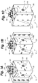
Figure 1A is a perspective view of an extrusion device in accordance with one embodiment of the present invention. -
Figure 1B is another perspective view of the extrusion device ofFigure 1 . -
Figure 1C is a still another perspective of the extrusion device ofFigure 1 . -
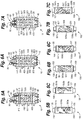
Figure 2A is a cross-sectional view of the extrusion device ofFigure 1 , with an adjustment valve shown in a first configuration such that the extrusion device is configured to produce extrudate having a first layer structure. -
Figure 2B is a left side view of a spool of the adjustment valve ofFigure 2A . -
Figure 2C is a right side view of the spool of the adjustment valve ofFigure 2B . -
Figure 3A is a cross-sectional view of the extrusion device ofFigure 1 , with the adjustment valve shown in a second configuration such that the extrusion device is configured to produce extrudate having a second layer structure. -
Figure 3B is a left side view of the spool of the adjustment valve ofFigure 3A . -
Figure 3C is a right side view of the spool of the adjustment valve ofFigure 3A . -
Figure 4A is a perspective view of an extrusion device in accordance with another embodiment of the invention. -
Figure 4B is another perspective view of the extrusion device ofFigure 4A . -
Figure 5A is a cross-sectional view of the extrusion device ofFigure 4A , with an adjustment valve shown in a first configuration such that the extrusion device is configured to produce extrudate having a first layer structure. -
Figure 5B is a front view of a spool of the adjustment valve ofFigure 5A . -
Figure 5C is a rear view of the spool of the adjustment valve ofFigure 5A . -
Figure 6A is a cross-sectional view of the extrusion device ofFigure 4A , with the adjustment valve shown in a second configuration such that the extrusion device is configured to produce extrudate having a second layer structure. -
Figure 6B is a front view of a spool of the adjustment valve ofFigure 6A . -
Figure 6C is a rear view of a spool of the adjustment valve ofFigure 6A . -
Figure 7A is a cross-sectional view of the extrusion device ofFigure 4A , with the adjustment valve shown in a second configuration such that the extrusion device is configured to produce extrudate having a second layer structure. -
Figure 7B is a front view of a spool of the adjustment valve ofFigure 7A . -
Figure 7C is a rear view of a spool of the adjustment valve ofFigure 7A . -
Figure 8A is a top view of an extrusion device in accordance with still another embodiment of the invention. -
Figure 8B is a perspective view of the extrusion device ofFigure 8A . -
Figure 8C is another perspective view of the extrusion device ofFigure 8A . -
Figure 8D is a cross-sectional view of the extrusion device ofFigure 8A , with an adjustment valve shown in a first configuration such that the extrusion device is configured to produce extrudate having a first layer structure. -
Figure 8E is a cross-sectional view of the extrusion device ofFigure 8A , with an adjustment valve shown in a second configuration such that the extrusion device is configured to produce extrudate having a second layer structure. -
Figure 8F is a cross-sectional view of the extrusion device ofFigure 8A , with an adjustment valve shown in a third configuration such that the extrusion device is configured to produce extrudate having a third layer structure. -
Figure 8G is a cross-sectional view of the extrusion device ofFigure 8A , with an adjustment valve shown in a fourth configuration such that the extrusion device is configured to produce extrudate having a fourth layer structure. -
Figure 8H is a cross-sectional view of the extrusion device ofFigure 8A , with an adjustment valve shown in a fifth configuration such that the extrusion device is configured to produce extrudate having a fifth layer structure. -
Figure 8I is a cross-sectional view of the extrusion device ofFigure 8A , with an adjustment valve shown in a sixth configuration such that the extrusion device is configured to produce extrudate having a sixth layer structure. -
Figure 9 is a perspective view of an extrusion device in accordance with yet another embodiment of the invention. -
Figure 10 is a cross-sectional view of the extrusion device ofFigure 9 . - In one embodiment, the invention provides an extrusion device having a body and an adjustment valve. The adjustment valve is rotatable between first and second operative positions. The extrusion device is configured to produce a first layer arrangement when the adjustment valve is in the first operative position, and the extrusion device is configured to produce a second layer arrangement when the adjustment valve is in the second operative position. The first and second layer arrangements are different.
- In another embodiment, the invention provides a method of using an extrusion device to produce different layer arrangements. The extrusion device comprises a body and an adjustment valve. The method comprises: (i) operating the extrusion device, while the adjustment valve is in a first operative position, to produce a first layer arrangement, and (ii) rotating the adjustment valve from the first operative position to a second operative position, and (iii) operating the extrusion device, while the adjustment valve is in the second operative position, to produce a second layer arrangement. The first and second layer arrangements are different.
- The following detailed description is exemplary in nature and is not intended to limit the scope, applicability, or configuration of the invention in any way. The description provides practical illustrations for implementing certain preferred embodiments of the invention. Examples of constructions, materials, dimensions, and manufacturing processes are provided for selected elements; all other elements employ that which is known to those of ordinary skill in the field of the invention. Those skilled in the present art will recognize that many of the given examples have a variety of suitable alternatives.
- The invention provides an
extrusion device 10 that is adjustable between first and second output configurations. Theextrusion device 10, when in the first output configuration, produces extrudate having a first layer arrangement, and when in the second output configuration, produces extrudate having a second layer arrangement. In some cases, theextrusion device 10 has only two output configurations (or "settings"). Reference is made to the embodiment ofFigures 1A-3C . In other cases, theextrusion device 10 has three or more output configurations, each adapted to produce a unique extrudate layer arrangement. Reference is made to the embodiment ofFigures 4A-7C . Depending upon the number of different layer arrangements the extrusion device is intended to produce, it can have six or more output configurations.Figures 8A-8I andFigures 9-10 respectfully depict two embodiments wherein theextrusion device 10 has six different output configurations. Thus, it is capable of producing six different extrudate layer arrangements. Depending upon the range of layer arrangements desired, the extrusion device can have more than six output configurations. - In the embodiments illustrated, the output configuration of the
extrusion device 10 can be changed without having to shut down the extrusion line. For example, one or more extruders delivering multiple polymer flows to theextrusion device 10 can continue operating while the layer arrangement produced by the device is changed. Theextrusion device 10 can optionally be adjustable (e.g., from being configured to produce extrudate having a first layer arrangement to being configured to produce extrude having a second layer arrangement) without having to remove any component and replace it with a different component. More generally, theextrusion device 10 can optionally be adjustable between different output configurations without having to disassemble any portion of the extrusion device (or at least no portion exposed to a flow path). - The
extrusion device 10 can be a coextrusion feedblock, a flow arranger located upstream of a feedblock, or any other device in which it would be desirable to change the arrangement of layers output from the device. - The
extrusion device 10 has abody 20 and anadjustment valve 50. Thebody 20 can be provided in different shapes and forms. InFigures 1A-1C and4A-4B , thebody 20 is a single block. The same is true of thebody 20 inFigures 4A and 4B . Thebody 20 can alternatively comprise multiple blocks. For example, thebody 20 of theextrusion device 10 shown inFigures 8A-8I comprises twoblocks Figures 9 and10 , thebody 20 of theextrusion device 10 comprises threeblocks Figure 10 . As shown inFigures 8B and 8C , the blocks can be joined together by a plurality of fasteners (e.g., bolts) 810. - The
body 20 has first 118 and second 128 inputs adapted to respectively receive first and second polymer flows from first and second extruders. Theadjustment valve 50 can be rotated between first and second operative positions while the first and second extruders continue delivering first and second polymer flows to the first 118 and second 128 inputs of thebody 20. Thus, the output can be changed without having to turn off the extruders. In the embodiments illustrated, thebody 20 has first 118, second 128, and third 138 inputs adapted to respectively receive first, second, and third polymer flows (e.g., from first, second, and third extruders). If desired, thebody 20 can be provided with inputs to receive polymer flows from four or five, or even more, extruders. - It is to be appreciated that the inputs can be provided at various different locations on the
body 20 of theextrusion device 10. Moreover, a single inlet can alternatively be provided to supply polymer to one or more flow lines of the extrusion device. - Thus, the
extrusion device 10 has abody 20 and anadjustment valve 50, which is rotatable between first and second operative positions. The rotational adjustment system of thepresent extrusion device 10 provides exceptional dynamic sealing. It also enables a particularly compact device profile. - When the
adjustment valve 50 is in the first operative position, theextrusion device 10 is configured to produce extrudate having a first layer arrangement. When theadjustment valve 50 is in the second operative position, theextrusion device 10 is configured to produce extrudate having a second layer arrangement. The first and second layer arrangements are different. For example, the first layer arrangement can be an "AB" layer arrangement, while the second layer arrangement is a "BA" layer arrangement. In the present disclosure, "A" refers to a layer formed by a first polymer flow (e.g., from a first extruder), while "B" refers to a layer formed by a second polymer flow (e.g., from a second extruder). Layer A will commonly have a different composition than layer B. For example, layers A and B may be formed of different polymers. In some cases, layer A will be one color while layer B is another color. - Referring to the embodiments of
Figures 1A-3C and4A-7C , thebody 20 of theextrusion device 10 has a plurality ofintake conduits output conduits body 20 has the same number "n" of (e.g., two or more, optionally three) intake conduits and output conduits, and the adjustment valve has the same number "n" of (not more) active extrudate channels. Thus, at any given time during operation, there can be "n" active extrudate channels in the adjustment valve, and at least "n" (optionally at least "2n") closed extrudate channels in the adjustment valve. The active extrudate channels are open to the respective intake conduits of thebody 20, while the closed extrudate channels are blocked off at both ends by confronting interior surfaces of the body (such that during operation, no extrudate can be flowed through the closed extrudate channels). - The
adjustment valve 50 has first and second sets ofextrudate channels adjustment valve 50 is in the first operative position, the first set ofextrudate channels extrudate channels adjustment valve 50 is in the second operative position, the second set ofextrudate channels extrudate channels - In the embodiments illustrated, the
adjustment valve 50 comprises aspool 150 and alock 90. Thespool 150 is rotatable and is shown having a cylindrical or generally cylindrical configuration. Reference is made toFigures 2B, 2C, 3B, 3C ,5B, 5C, 6B, 6C, 7B, and 7C . Thebody 20 of the illustratedextrusion device 10 has a generally cylindrical opening in which thespool 150 is mounted. The illustratedspool 150 is mounted in thebody 20 of extrusion device such that the spool has no freedom (or substantially no freedom) to move axially (i.e., up or down as shown inFigures 2A-3C ) relative to thebody 20 of the extrusion device. Thus, movement of the illustrated adjustment valve involves rotation of the spool, but no axial movement of the spool. In the embodiments illustrated, this is accomplished by mounting the spool between twocaps body 20 of theextrusion device 10. Alternatively, the spool can be mounted between a cap (such as cap 40) and an inwardly turned shoulder of thebody 20 itself. - The illustrated
lock 90 has a locked configuration and an unlocked configuration. Thespool 150 is rotatable relative to thebody 20 when thelock 90 is in the unlocked configuration. In contrast, thespool 150 is locked against rotation relative to thebody 20 when the lock is in the locked position. Thelock 90 can be, for example, a quick release pin. This is perhaps best shown inFigures 1A-1C ,2A ,3A ,4A ,4B ,5A, 6A, 7A ,8A , and9 . In these embodiments, to adjust the extrusion device from one output configuration to another, an operator can simply pull the quick release pin, rotate the adjustment valve to the desired operative position, and re-engage the quick release pin, thereby locking the adjustment valve against rotation relative to the body. - If so desired, the
body 20 may have a cylindrical opening in which the spool is mounted, and the body may be devoid of flushing channels (e.g., of the type that extend parallel to the axis of that cylindrical opening). - The
adjustment valve 50 is adapted to rotate in increments when moving from one operative position to the next. Thus, theadjustment valve 50 has a plurality of different operative positions such that each two adjacent operative positions are separated by an angular increment. If desired, each two adjacent operative positions can be separated by the same angular increment (e.g., 45 degrees). This, however, is by no means required. - In the embodiments illustrated, the
adjustment valve 50 comprises aspool 150 with a generally cylindrical configuration. Thespool 150 is mounted in a generally cylindrical opening of thebody 20. Thespool 150 has abody portion 157, which has the extrudate channels. The illustratedspool 150 has opposed first 155 and second 159 neck portions, which define opposite ends of the spool. Thebody portion 157, thefirst neck portion 155, and thesecond neck portion 159 preferably each have a cylindrical or generally cylindrical configuration. The twoneck portions body portion 157 and each has a smaller diameter than the body portion. - The illustrated
spool 150 is mounted in a cylindrical or generally cylindrical opening of thebody 20 between twocaps caps body 20. Abushing 47 can optionally be provided between eachcap spool 150. In the embodiments illustrated, abushing 47 is provided on eachneck portion spool 150. Atrunnion 60 is fastened (e.g., bolted) to thefirst neck portion 155 of the spool. The illustratedtrunnion 60 has ahex cap 65, which an operator can conveniently rotate using a socket, a wrench, etc. - Thus, the illustrated spool configuration has a
body portion 157 and two reduced-diameter neck portions body portion 157 defines a shoulder with anannular surface 158. Theannular surface 158 adjacent thefirst neck portion 155 can have a series of openings spaced apart along a circumference of the surface. The quick release pin can be engaged selectively with any one of these openings in order to lock the spool in a desired operative position. This is perhaps best shown inFigures 2A, 3A ,5A, 6A ,7A , and8D-8I . Each of these openings corresponds to a different operative position of theadjustment valve 50. Thus, as noted above, the quick release pin can be pulled out of thespool 150, thereby freeing the spool to rotate relative to thebody 20. An operator can then use a socket or another suitable tool to grip thehex cap 65 on thetrunnion 60 and rotate thespool 150 until the desired opening in the adjacentannular shoulder surface 158 is aligned with the pin, at which point the pin can be inserted into that opening, thereby locking thespool 150 in the desired operative position. - The spool can alternatively be configured such that there is only one neck portion (e.g., the first neck portion 155), rather than two as shown. Another option is to eliminate both
neck portions spool 150 consists of thebody portion 157 and is a right circular cylinder. If so desired, the or each spool in any embodiment hereof can be devoid of (i.e., such that the spool does not house) a cartridge heater. - Each
spool 150 has a plurality of extrudate channels. While the number of extrudate channels in thespool 150 will vary from embodiment to embodiment, there will typically be at least four, in many cases at least six, and in some cases at least nine, extrudate channels in thespool 150. InFigures 2A-3C , thespool 150 has six extrudate channels 51-56. InFigures 5A-7C , thespool 150 has nine extrudate channels 501-509. The particular number of extrudate channels will vary based upon the requirements of different systems. In the embodiments illustrated, each spool has at least three openings (e.g., inlets) for passage of extruded material into the spool and at least three outlets for passage of extruded material out of the spool. - The
body portion 157 of each illustratedspool 150 has at least one channel that extends radially in straight line across an entire diameter of the body portion. In the embodiments illustrated, thebody portion 157 of eachspool 150 has at least two such diametrical through-channels. Reference is made tochannels Figures 2A-2C ,channel 55 inFigures 3A-3C , andchannels Figures 5A-5C . In addition to having one or more diametrical through-channels, thebody portion 157 can advantageously have at least one arcuate channel, i.e., a channel extending along a curved path. Each of thespools 150 shown inFigures 2A-3C ,5A-7C , and8D-8I has abody portion 157 with a plurality of arcuate channels. One or more (optionally each) of these channels may be open through an outer surface of the body portion 157 (e.g., through a cylinder surface thereof) along a desired length of the channel. In some cases, a channel of this nature is open through the outer surface of the body portion along the entire length of the channel. Reference is made tochannels Figures 2A-3C , andchannels Figures 6A-7C . In other cases, a curved channel has a total length that includes a first length and a second length, where the channel is open through the outer surface of the body portion along the first length, while the second length of the channel extends radially through thebody portion 157 of thespool 150. Reference is made to channel 51 inFigures 2A-3C , andchannels Figures 5A-7C . In some cases, a radially extending length of a channel extends between two curved lengths of the channel. Reference is made tochannels Figures 5A-7C . Furthermore, thespool 150 can optionally include at least one channel having a first length extending straight across the diameter of thebody portion 157 and one or two lengths that each extend axially in a straight line. Reference is made to channel 55 inFigures 3A-3C . - Thus, the
body portion 157 of thespool 150 can have a plurality of diametrical through-channels as well as a plurality of curved channels, which can optionally be open along an outer surface of the body portion (e.g., through a cylinder surface thereof). - In the embodiments illustrated, each extrudate channel extends between an
entrance port spool 150, and anexit port body 20, through the desired extrudate channel in thespool 150, and into an output conduit of thebody 20. - Referring to
Figures 1C ,2A ,3A ,4B ,5A, 6A, 7A ,8A , and8D-8I , the illustratedextrusion device 10 has threeoutput conduits body 20 generally parallel to a machine direction (see arrow A inFigure 8A ) of the extrusion device. These output conduits are configured to deliver extrudate out of theextrusion device 10. Theadjustment valve 50 is rotatable, relative to thebody 20, about a rotation axis perpendicular to the machine direction A of the illustratedextrusion device 10. - Thus, the illustrated
extrusion device 10 has three flow lines each extending through thebody 20 and through theadjustment valve 50. Thebody 20 and theadjustment valve 50 preferably are configured such that, during rotation of theadjustment valve 50 from the first operative position to the second operative position, all three of the flow lines always remain open. In other embodiments, the extrusion device has only two flow lines. When the adjustment valve rotates from one operative position to another, the path (or "route") of each flow line changes, and a slight pressure increase may occur, but the flow lines will never be closed entirely. - Referring now to the embodiment of
Figures 2A-3C , thebody 20 of theextrusion device 10 has first 110, second 120, and third 130 intake conduits as well as first 210, second 220, and third 230 output conduits. Theadjustment valve 50 has first 51, second 52, third 53, fourth 54, fifth 55, and sixth 56 extrudate channels. When theadjustment valve 50 is in the first operative position, thefirst intake conduit 110 is in fluid communication with thefirst extrudate channel 51 and thefirst output conduit 210, while thesecond intake conduit 120 is in fluid communication with thesecond extrudate channel 52 and thesecond output conduit 220, and while thethird intake conduit 130 is in fluid communication with thethird extrudate channel 53 and thethird output conduit 230. When theadjustment valve 50 is in the second operative position, thefirst intake conduit 110 is in fluid communication with thefourth extrudate channel 54 and thethird output conduit 230, while thesecond intake conduit 120 is in fluid communication with thefourth extrudate channel 55 and thesecond output conduit 220, and while thethird intake conduit 130 is in fluid communication with thesixth extrudate channel 56 and thefirst output conduit 210. - With continued reference to the embodiment of
Figures 2A-3C , thebody 20 and theadjustment valve 50 are configured such that at all times during rotation of the adjustment valve between the first and second operative positions: (i) thefirst intake conduit 110 is in fluid communication with thefirst extrudate channel 51, thefourth extrudate channel 54, or both, (ii) thesecond intake conduit 120 is in fluid communication with thesecond extrudate channel 52, the fifth extrudate channel (55), or both, and (iii) thethird intake conduit 130 is in fluid communication with thethird extrudate channel 53, thesixth extrudate channel 56, or both. Preferably, during rotation of theadjustment valve 50 from the first operative position to the second operative position: (a) thefirst intake conduit 110 is initially open only to thefirst extrudate channel 51, then is open to both thefirst extrudate channel 51 and thefourth extrudate channel 54, and finally is open only to thefourth extrudate channel 54, (b) thesecond intake conduit 120 is initially open only to thesecond extrudate channel 52, then is open to both thesecond extrudate channel 52 and thefifth extrudate channel 55, and finally is open only to thefifth extrudate channel 55, and (c) thethird intake conduit 130 is initially open only to thethird extrudate channel 53, then is open to both thethird extrudate channel 53 and thesixth extrudate channel 56, and finally is open only to thesixth extrudate channel 56. - In the embodiment of
Figures 5A-7C , theadjustment valve 50 is rotatable between first, second, and third operative positions. Thus, theextrusion device 10 in this embodiment is configured to produce: a first layer arrangement when theadjustment valve 50 is in a first operative position, a second layer arrangement when theadjustment valve 50 is in the second operative position, and a third layer arrangement when theadjustment valve 50 is in the third operative position. The first, second, and third layer arrangements are different. In one example, the first layer arrangement is a 1/2/3 layer arrangement, while the second layer arrangement is a 1/3/2 layer arrangement, and the third layer arrangement is a 2/1/3 layer arrangement. In another example, the first layer arrangement is a 1/2/1 layer arrangement, while the second layer arrangement is a 1/1/2 layer arrangement, and the third layer arrangement is a 2/1/1 layer arrangement. - With continued reference to
Figures 5A-7C , thebody 20 of theextrusion device 10 has a plurality ofintake conduits output conduits adjustment valve 50 has first, second, and third sets ofextrudate channels adjustment valve 50 is in the first operative position, the first set ofextrudate channels intake conduits output conduits extrudate channels adjustment valve 50 is in the second operative position, the second set ofextrudate channels intake conduits output conduits extrudate channels adjustment valve 50 is in the third operative position, the third set ofextrudate channels intake conduits output conduits extrudate channels - In
Figures 5A-7C , thebody 20 of theextrusion device 10 has first 310, second 320, and third 330 intake conduits as well as first 410, second 420, and third 430 output conduits. In this embodiment, theadjustment valve 50 has first 501, second 502, third 503, fourth 504, fifth 505, sixth 506, seventh 507, eighth 508, and ninth 509 extrudate channels. When theadjustment valve 50 is in the first operative position, thefirst intake conduit 310 is in fluid communication with thefirst extrudate channel 501 and thefirst output conduit 410, while thesecond intake conduit 320 is in fluid communication with thesecond extrudate channel 502 and thesecond output conduit 420, and while thethird intake conduit 330 is in fluid communication with thethird extrudate channel 503 and thethird output conduit 430. When theadjustment valve 50 is in the second operative position, thefirst intake conduit 310 is in fluid communication with thefourth extrudate channel 504 and thefirst output conduit 410, while thesecond intake conduit 320 is in fluid communication with thefifth extrudate channel 505 and thethird output conduit 430, and while thethird intake conduit 330 is in fluid communication with thesixth extrudate channel 506 and thesecond output conduit 420. When theadjustment valve 50 is in the third operative position, thefirst intake conduit 310 is in fluid communication with theseventh extrudate channel 507 and thesecond output conduit 420, while thesecond intake conduit 320 is in fluid communication with theeighth extrudate channel 508 and thefirst output conduit 410, and while thethird intake conduit 330 is in fluid communication with theninth extrudate channel 509 and thethird output conduit 430. - In the two embodiments shown respectfully in
Figures 8A-8I andFigures 9-10 , theextrusion device 10 further includes a second adjustment valve 50'. In these embodiments, the second adjustment valve 50' is rotatable between first, second, and third operative positions. The twoadjustment valves 50, 50' can comprise two spools each optionally being cylindrical or generally cylindrical and configured such that their two respective cylinder axes are parallel to each other. The second adjustment valve is downstream of the first adjustment valve. Theextrusion device 10 is configured to produce different layer arrangements when the second adjustment valve 50' is in the first operative position than when the second adjustment valve is in the second or third operative position. The second adjustment valve 50' can be of the nature described above relative to thefirst adjustment valve 50. InFigures 8A-10 , theextrusion device 10 has three flow lines, each extending through thebody 20 and through both of theadjustment valves 50, 50'. In the present embodiments, theextrusion device 10 has six different output configurations (or "settings"), each characterized by a unique combination of thefirst adjustment valve 50 being in the first or second position while the second adjustment valve 50' is in the first, second, or third position. Thus, theextrusion device 10 is adapted to produce six different layer arrangements. - For purposes of illustration, the adjustment valve/spool design from
Figures 1A-3C is used for thefirst adjustment valve 50 in the embodiment ofFigures 8A-8I , and the adjustment valve/spool design fromFigures 4A-7C is used for the second adjustment valve 50' in the embodiment ofFigures 8A-8I . It is to be appreciated, however, that for other embodiments involving two or more adjustment valves, many other valve/spool designs can be used. -
Figure 8D shows theextrusion device 10 in a first output configuration (or "first setting"). When theextrusion device 10 is in this output configuration, the resulting layer arrangement can be an A/B/C layer structure. Thus, thefirst spool 150 is shown in an "ABC" operative position, while thesecond spool 150 is shown in a "123" operative position. -
Figure 8E shows theextrusion device 10 in a second output configuration (or "second setting"). When theextrusion device 10 is in this output configuration, the resulting layer arrangement can be a B/A/C layer structure. Thus, thefirst spool 150 is shown in an "ABC" operative position, while thesecond spool 150 is shown in a "132" operative position. -
Figure 8F shows theextrusion device 10 in a third output configuration (or "third setting"). When theextrusion device 10 is in this output configuration, the resulting layer arrangement can be a B/A/C layer structure. Thus, thefirst spool 150 is shown in an "ABC" operative position, while thesecond spool 150 is shown in a "213" operative position. -
Figure 8G shows theextrusion device 10 in a fourth output configuration (or "fourth setting"). When theextrusion device 10 is in this output configuration, the resulting layer arrangement can be a C/B/A layer structure. Thus, thefirst spool 150 is shown in a "CBA" operative position, while thesecond spool 150 is shown in a "123" operative position. -
Figure 8H shows theextrusion device 10 in a fifth output configuration (or "fifth setting"). When theextrusion device 10 is in this output configuration, the resulting layer arrangement can be a C/A/B layer structure. Thus, thefirst spool 150 is shown in a "CBA" operative position, while thesecond spool 150 is shown in a "132" operative position. -
Figure 8I shows theextrusion device 10 in a sixth output configuration (or "sixth setting"). When theextrusion device 10 is in this output configuration, the resulting layer arrangement can be a B/C/A layer structure. Thus, thefirst spool 150 is shown in a "CBA" operative position, while thesecond spool 150 is shown in a "213" operative position. - In the embodiment of
Figures 9 and10 , theextrusion device 10 is a coextrusion feedblock. This can be the case in any embodiment of the present disclosure. Thus, downstream from the adjustment valve(s), theextrusion device 10 can have a flow-combining region where multiple flow lines passing through the extrusion device converge and are joined to form asingle outflow conduit 300. In the illustrated embodiment, the feedblock has a singlecentral outflow conduit 300 and twocoextrusion conduits 200. The twocoextrusion conduits 200 converge with each other and ultimately intersect with theoutflow conduit 300. - The configuration of the
outflow conduit 300 can be varied to suit different applications. InFigures 9 and10 , a singlecentral outflow conduit 300 extends along a straight path located in the middle of the feedblock. This, however, is not required. For example, the central outflow conduit need not be located at the middle of the feedblock. Instead, it may be closer to the top or bottom of the feedblock. The central outflow conduit may be curved or angled, although it will generally be desirable to minimize the flow resistance in the conduit. Moreover, in some cases, layers from one ormore coextrusion conduits 200 are applied to one side, but not both sides, of the core layer delivered from the central outflow conduit. In such cases, one or more coextrusion conduits are located on one side of thecentral outflow conduit 300, but not on the other side. - In
Figures 9 and10 , the feedblock has asingle outflow conduit 300 and twocoextrusion conduits 200. A feedblock of this nature will commonly be used to produce a 3-layer coextrusion structure. Skilled artisans will appreciate, however, that a single or double-layer coextrusion structure can be produced with such a feedblock. This can be done, for example, by not using and closing one or both of thecoextrusion conduits 200. More generally, the number and arrangement ofcoextrusion conduits 200 can be varied to accommodate many different applications. The feedblock, for example, can alternatively have a single coextrusion conduit. As another example, when a 5-layer coextrusion structure is desired, the feedblock will typically have at least four coextrusion conduits. Many other variants of this nature will be apparent to skilled artisans given the present teaching as a guide. - In
Figures 9 and10 , eachcoextrusion conduit 200 opens into theoutflow conduit 300, such that the secondary extrudate flow in each coextrusion conduit merges with the extrudate flow in the outflow conduit, thus producing a multi-layer extrudate flow. The layer delivered from the central flow is referred to as the core layer. One or more layers from the coextrusion conduit(s) are layered onto the core layer. The resulting multi-layer extrudate flow moves along theoutflow conduit 300 until reaching theoutlet 309. From theoutlet 309, the multi-layer extrudate flow may be delivered to an extrusion die or another downstream tool, such as a layer multiplier or another feedblock. - The
body 20 of the feedblock shown inFigures 9 and10 can optionally comprise fourblocks 20' joined together. The illustratedcentral outflow conduit 300, for example, can extend along a path located at an interface of twosuch blocks 20', which collectively surround, and are each exposed to, the central conduit. In other cases, two such blocks can be replaced by a single block defining both halves of this portion of the feedblock. The illustrated feedblock also has anoutput plate 590, although this is not required. - The feedblock shown in
Figures 9 and10 has twoflow adjusters 700. In other embodiments, there may be only one flow adjuster, four or more flow adjusters, or none. When provided, eachflow adjuster 700 preferably is rotatable and wedge shaped. Eachflow adjuster 700 may be rotatable about a rotation axis that is perpendicular or generally perpendicular to the rotation axis/axes of the/eachadjustment valve 50, 50'. In the illustrated embodiment, eachflow adjuster 700 is rotatable to simultaneously change: i) the gap height of theadjacent coextrusion conduit 200, and ii) a height of thecentral outflow conduit 300. Thus, the flow adjuster(s) 700 is/are downstream from the adjustment valve(s) 50, 50'. - The illustrated
flow adjusters 700 each have first and second flow-contacting surfaces. The first flow-contactingsurface 758 is exposed to thecentral outflow conduit 300, and the second flow-contactingsurface 752 is exposed to thecoextrusion conduit 200. The second flow-contactingsurface 752 preferably has a concave configuration. - Each illustrated
flow adjuster 700 has a cylindrical base region from which projects a wedge region that narrows with increasing distance from the cylindrical base region until reaching a tip where the extrudate flows from thecentral outflow conduit 300 and therespective coextrusion conduit 200 intersect. This is shown inFigure 10 , which illustrates a flow-combining region of the feedblock where twocoextrusion conduits 200 merge with thecentral outflow conduit 300. Eachcoextrusion conduit 200 has an outlet that opens into thecentral outflow conduit 300. Thus, the illustrated feedblock 500 has a flow-combining region where multiple extrudate flows are combined to form a multi-layer extrudate flow. InFigure 10 , the height of thecentral outflow conduit 300 at a location entering the flow-combining region is set by the separation distance between the confronting pair ofadjustable flow adjusters 700. - In the embodiment of
Figure 10 , the feedblock hasgauges 800 that indicate the position of the respective adjustable wedge-shapedflow controller 700. The illustrated gauges are merely exemplary; various different gauge types can be used. Moreover, the gauges are optional and may be omitted in some cases. - Thus, the feedblock shown in
Figures 9 and10 has twocoextrusion conduits 200 and twoflow adjusters 700. The configuration, functionality, and other features of thesecoextrusion conduits 200 and flow adjusters 700 (including any actuators) can optionally be of the nature described inU.S. patent application No. 13/646,206 , the entire teachings of which are incorporated herein by reference. In other embodiments, the feedblock can have one or more viscosity compensation devices of the type disclosed inU.S. patent application No. 14/445,604 . More generally, depending upon the applications intended for the feedblock, it can have any suitable viscosity compensation system or layer profiling devices, or none at all. - Another embodiment of the invention provides a method of using an
extrusion device 10 to produce different layer arrangements. Theextrusion device 10 has abody 20 and anadjustment valve 50. The method involves operating theextrusion device 10, while theadjustment valve 50 is in a first operative position, to produce a first layer arrangement. Theadjustment valve 50 is then rotated from the first operative position to a second operative position, and theextrusion device 10 is operated (while the adjustment valve is in the second operative position) to produce a second layer arrangement. As noted above, the first and second layer arrangements are different. - The method may include delivering first, second, and third polymer flows respectively to first, second, and
third inputs body 20 continuously during rotation of theadjustment valve 50 from the first operative position to the second operative position (as well as during any other rotation of the/each adjustment valve from one operative position to another). Since the output configuration of theextrusion device 10 can be changed without having to shut down the extrusion line, the extruder(s) delivering polymer flows to the device can continue operating while the layer arrangement produced by the device is changed. - The illustrated
adjustment valve 10 is rotated from the first operative position to the second operative position without removing any component of theextrusion device 10 and replacing such component with a different component. It is unnecessary, for example, to remove and replace flow inserts, diverters, plugs, flow spools, and/or selector plates before adjusting theextrusion device 10 from one output configuration to another. More generally, theextrusion device 10 can optionally be adjustable between different output configurations without disassembling any portion of the extrusion device (or at least any portion exposed to extrudate flow). - The rotational adjustment method of the present invention provides exceptional dynamic sealing. It also enables a particularly compact device profile. In the embodiments illustrated, rotation of the
adjustment valve 50 is relative to thebody 20 and about a rotation axis perpendicular to a machine direction (see arrow A inFigure 8A ) of theextrusion device 10. - The illustrated
extrusion device 10 has three flow lines each extending through thebody 20 and through the adjustment valve (50). During rotation of theadjustment valve 50, all three of these flow lines always remain open. This is also the case for each flow line in embodiments having fewer (only two) or more than three flow lines. When the adjustment valve rotates from one operative position to another, the path (or "route") of each flow line changes, and while a slight pressure increase may occur, the flow lines will never be closed entirely. - When the
adjustment valve 50 is in the first operative position, a first set ofextrudate channels adjustment valve 50 is open to a plurality ofintake conduits output conduits body 20, while a second set ofextrudate channels adjustment valve 50 is in the second operative position, the second set ofextrudate channels intake conduits output conduits extrudate channels body 20, then through "n" (not more) active extrudate channels of the or each adjustment valve, and then through "n" output conduits of the body. As will be appreciated, such methods do not involve flowing extrudate through closed extrudate channels of the or each adjustment valve, and need not involve flowing extrudate through any flushing channels while flow is being delivered to the active extrudate channels. - As noted above, some embodiments involve an
adjustment valve 50 that is rotatable between first, second, and third operative positions. In such cases, the method further involves rotating theadjustment valve 50 from the second operative position to a third operative position, and operating the extrusion device 10 (while the adjustment valve is in the third operative position) to produce a third layer arrangement. The first, second, and third layer arrangements are different. When theadjustment valve 50 is in the third operative position, a third set ofextrudate channels adjustment valve 50 is open to theintake conduits output conduits extrudate channels adjustment valve 50 may have four or more operative positions. Thus, the present method may involve rotating theadjustment valve 50 among four or more operative positions. - The
coextrusion device 10 used in the present method can be a feedblock of the nature described above with reference toFigures 9 and10 . Thus, the present method can involve extruding a first flow of extrudate through acentral output conduit 300 while simultaneously extruding at least a second flow of extrudate through acoextrusion conduit 200. In many cases, the method involves extruding the first extrudate flow through thecentral output conduit 300 while simultaneously extruding two other extrudate flows respectfully through twocoextrusion conduits 200. Thus, the first flow and the second flow(s) preferably are combined, at an intersection of theoutput conduit 300 and the coextrusion conduit(s) 200, to produce a multi-layer extrudate flow. - As noted above, the feedblock of
Figures 9 and10 has twoflow adjusters 700, which preferably are each rotatable and wedge shaped. Thus, the present method can optionally involve rotating theflow adjusters 700 to simultaneously adjust the gap height of eachcoextrusion conduit 200 and a height of thecentral output conduit 300. - While preferred embodiments of the invention have been described, it should be understood that various changes, adaptations and modifications may be made therein without departing from the spirit of the invention and the scope of the appended claims.
Claims (11)
- An extrusion device having a body and an adjustment valve, said adjustment valve rotatable between first and second operative positions, said extrusion device configured to produce a first layer arrangement when said adjustment valve is in said first operative position, said extrusion device configured to produce a second layer arrangement when said adjustment valve is in said second operative position, said first and second layer arrangements being different.
- The extrusion device of claim 1 wherein said body has first, second, and third inputs to respectively receive first, second, and third polymer flows, said adjustment valve being rotatable between said first and second operative positions while the first, second, and third polymer flows are delivered to said first, second, and third inputs of said body, said extrusion device having three flow lines each extending through said body and through said adjustment valve, said body and said adjustment valve configured such that, during rotation of said adjustment valve between said first and second operative positions, all three of said flow lines remain open.
- The extrusion device of claim 1 wherein said body has a plurality of intake conduits and a plurality of output conduits, said adjustment valve having first and second sets of extrudate channels, wherein when said adjustment valve is in said first operative position said first set of extrudate channels is open to said intake conduits and to said output conduits while said second set of extrudate channels is closed off from said intake conduits and from said output conduits, and wherein when said adjustment valve is in said second operative position said second set of extrudate channels is open to said intake conduits and to said output conduits while said first set of extrudate channels is closed off from said intake conduits and from said output conduits.
- The extrusion device of claim 1 wherein said body has first, second, and third intake conduits and first, second, and third output conduits, and said adjustment valve has first, second, third, fourth, fifth, and sixth extrudate channels, wherein when said adjustment valve is in said first operative position said first intake conduit is in fluid communication with said first extrudate channel and said first output conduit while said second intake conduit is in fluid communication with said second extrudate channel and said second output conduit and while said third intake conduit is in fluid communication with said third extrudate channel and said third output conduit, and wherein when said adjustment valve is in said second operative position said first intake conduit is in fluid communication with said fourth extrudate channel and said third output conduit while said second intake conduit is in fluid communication with said fourth extrudate channel and said second output conduit and while said third intake conduit is in fluid communication with said sixth extrudate channel and said first output conduit, said body and said adjustment valve configured such that during rotation of said adjustment valve from said first operative position to said second operative position:(a) said first intake conduit is initially open only to said first extrudate channel, then is open to both said first extrudate channel and said fourth extrudate channel, and finally is open only to said fourth extrudate channel,(b) said second intake conduit is initially open only to said second extrudate channel, then is open to both said second extrudate channel and said fifth extrudate channel, and finally is open only to said fifth extrudate channel, and(c) said third intake conduit is initially open only to said third extrudate channel, then is open to both said third extrudate channel and said sixth extrudate channel, and finally is open only to said sixth extrudate channel.
- The extrusion device of claim 1 wherein said adjustment valve is rotatable between first, second, and third operative positions, said extrusion device configured to produce the first layer arrangement when said adjustment valve is in said first operative position, said extrusion device configured to produce the second layer arrangement when said adjustment valve is in said second operative position, said extrusion device configured to produce a third layer arrangement when said adjustment valve is in said third operative position, said first, second, and third layer arrangements being different, said body having a plurality of intake conduits and a plurality of output conduits, said adjustment valve having first, second, and third sets of extrudate channels, wherein when said adjustment valve is in said first operative position said first set of extrudate channels is open to said intake conduits and to said output conduits while said second and third sets of extrudate channels are closed off from said intake conduits and from said output conduits, and wherein when said adjustment valve is in said second operative position said second set of extrudate channels is open to said intake conduits and to said output conduits while said first and third sets of extrudate channels are closed off from said intake conduits and from said output conduits, and wherein when said adjustment valve is in said third operative position said third set of extrudate channels is open to said intake conduits and to said output conduits while said first and second sets of extrudate channels are closed off from said intake conduits and from said output conduits.
- The extrusion device of claim 1 wherein said adjustment valve comprises a spool and a lock, said lock having a locked configuration and an unlocked configuration, said body having a generally cylindrical opening in which said spool is mounted, said spool being rotatable relative to said body when said lock is in said unlocked configuration, said spool) being locked against rotation relative to said body when said lock is in said locked position.
- The extrusion device of claim 1 further including a second adjustment valve, said second adjustment valve rotatable between first, second, and third operative positions, said extrusion device configured to produce different layer arrangements when said second adjustment valve is in said first operative position than when said second adjustment valve is in said second or third operative position, said extrusion device having three flow lines each extending through said body and through both of said adjustment valves, said extrusion device having six different settings each characterized by a unique combination of said first adjustment valve being in said first or second position while said second adjustment valve is in said first, second, or third position, such that said extrusion device is adapted to produce six different layer arrangements.
- A method of using an extrusion device to produce different layer arrangements, said extrusion device comprising a body and an adjustment valve, the method comprising:i) operating said extrusion device, while said adjustment valve is in a first operative position, to produce a first layer arrangement,ii) rotating said adjustment valve from said first operative position to a second operative position, andiii) operating said extrusion device, while said adjustment valve is in said second operative position, to produce a second layer arrangement, said first and second layer arrangements being different.
- The method of claim 8 comprising delivering first, second, and third polymer flows respectively to first, second, and third inputs of said body continuously throughout said rotation of said adjustment valve from said first operative position to said second operative position.
- The method of claim 8 wherein when said adjustment valve is in said first operative position a first set of extrudate channels in said adjustment valve is open to a plurality of intake conduits and a plurality of output conduits in said body while a second set of extrudate channels in said adjustment valve is closed off from said intake conduits and from said output conduits, and wherein when said adjustment valve is in said second operative position said second set of extrudate channels is open to said intake conduits and to said output conduits while said first set of extrudate channels is closed off from said intake conduits and from said output conduits.
- The method of claim 10 further comprising rotating said adjustment valve from said second operative position to a third operative position, and operating said extrusion device, while said adjustment valve is in said third operative position, to produce a third layer arrangement, said first, second, and third layer arrangements being different, wherein when said adjustment valve is in said third operative position a third set of extrudate channels in said adjustment valve is open to said intake conduits and to said output conduits while said first and second sets of extrudate channels are closed off from said intake conduits and from said output conduits.
Applications Claiming Priority (1)
| Application Number | Priority Date | Filing Date | Title |
|---|---|---|---|
| US14/703,069 US10220561B2 (en) | 2015-05-04 | 2015-05-04 | Extrusion device and method of use |
Publications (2)
| Publication Number | Publication Date |
|---|---|
| EP3098054A2 true EP3098054A2 (en) | 2016-11-30 |
| EP3098054A3 EP3098054A3 (en) | 2017-02-15 |
Family
ID=55806145
Family Applications (1)
| Application Number | Title | Priority Date | Filing Date |
|---|---|---|---|
| EP16164924.9A Withdrawn EP3098054A3 (en) | 2015-05-04 | 2016-04-12 | Extrusion device and method of use |
Country Status (4)
| Country | Link |
|---|---|
| US (1) | US10220561B2 (en) |
| EP (1) | EP3098054A3 (en) |
| JP (1) | JP6781571B2 (en) |
| CN (1) | CN106113432B (en) |
Cited By (1)
| Publication number | Priority date | Publication date | Assignee | Title |
|---|---|---|---|---|
| IT202100027194A1 (en) * | 2021-10-22 | 2023-04-22 | Diego GALLI | DEVICE FOR THE PRODUCTION OF A MULTI-LAYER COMPOSITE PRODUCT |
Families Citing this family (6)
| Publication number | Priority date | Publication date | Assignee | Title |
|---|---|---|---|---|
| US10252457B2 (en) | 2015-05-04 | 2019-04-09 | Nordson Corporation | Flow diverter valve for an extrusion system |
| US10220561B2 (en) | 2015-05-04 | 2019-03-05 | Nordson Corporation | Extrusion device and method of use |
| JP6561254B2 (en) * | 2015-07-10 | 2019-08-21 | 川上産業株式会社 | Synthetic resin hollow plate, manufacturing apparatus and manufacturing method thereof, and extrusion molding apparatus |
| DE102018216149B4 (en) * | 2018-09-21 | 2023-05-25 | Fraunhofer-Gesellschaft zur Förderung der angewandten Forschung e.V. | Device for influencing the volume flow of extruded plastically deformable material |
| JP6916565B2 (en) * | 2019-05-14 | 2021-08-11 | 株式会社プラ技研 | Flexible tube manufacturing equipment |
| CN120171017B (en) * | 2025-05-22 | 2025-08-01 | 高密市立达橡塑制品有限公司 | Adjustable extrusion head for rubber rim strip machining and working method thereof |
Citations (4)
| Publication number | Priority date | Publication date | Assignee | Title |
|---|---|---|---|---|
| JPS6027515A (en) * | 1983-07-27 | 1985-02-12 | Toshiba Mach Co Ltd | Resin changeover valve of multilayer t-die extruder |
| JPS61273924A (en) * | 1985-05-29 | 1986-12-04 | Shin Kobe Electric Mach Co Ltd | Resin flow path setting plug for co-extrusion |
| JPS61273925A (en) * | 1985-05-29 | 1986-12-04 | Shin Kobe Electric Mach Co Ltd | Resin flow path setting plug for co-extrusion |
| JPS61273926A (en) * | 1985-05-29 | 1986-12-04 | Shin Kobe Electric Mach Co Ltd | Resin flow path setting plug for co-extrusion |
Family Cites Families (26)
| Publication number | Priority date | Publication date | Assignee | Title |
|---|---|---|---|---|
| CA1007015A (en) * | 1971-09-27 | 1977-03-22 | Walter J. Schrenk | Coextrusion apparatus |
| US3918865A (en) | 1973-09-28 | 1975-11-11 | Welex Inc | Coextrusion system |
| US3886963A (en) | 1973-10-10 | 1975-06-03 | Dow Chemical Co | Valve |
| AU513695B2 (en) | 1976-02-20 | 1980-12-18 | Ihara Chemical Ind Co | Multiport cylindrical valve |
| US4249875A (en) | 1978-09-15 | 1981-02-10 | Cosden Technology, Inc. | Co-extrusion apparatus and method for producing multiple-layered thermoplastic pipe |
| FR2437289A1 (en) * | 1978-09-27 | 1980-04-25 | Ono | Extrusion manifold for laminating several pre:plasticised melts - comprising series of interchangeable discs with transverse and radial flow passages (J5 2.4.80) |
| US4483669A (en) | 1982-08-16 | 1984-11-20 | Cosden Technology, Inc. | Multiple-layered sheeting apparatus |
| US4931246A (en) | 1983-04-13 | 1990-06-05 | American National Can Company | Method for injection molding multi-layer articles |
| AT387671B (en) * | 1987-01-27 | 1989-02-27 | Rosendahl Masch Gmbh | METHOD AND DEVICE FOR PRODUCING INSULATED WIRE |
| US4761129A (en) * | 1987-07-07 | 1988-08-02 | Swisscab E.A. Schoen S.A. | Device for changing color during the extrusion of a sheath around a conductor |
| US5110276A (en) | 1989-12-28 | 1992-05-05 | Farnsworth John T | Extrusion die assembly |
| US5076777A (en) | 1990-12-20 | 1991-12-31 | Cincinnati Milacron Inc. | Apparatus for coextruding plastics materials |
| US5616350A (en) | 1995-04-10 | 1997-04-01 | Cincinnati Milacron Inc. | Dual flow divider with diverter valve |
| US5858420A (en) | 1997-08-13 | 1999-01-12 | Husky Injection Molding Systems Ltd. | Flow regulating and distributing assembly |
| US6174478B1 (en) | 1998-09-25 | 2001-01-16 | Silver-Line Plastics Corporation | Method and apparatus for simultaneous extrusion of two triple-wall pipes |
| DE60030514T2 (en) | 1999-08-12 | 2007-07-05 | Sumitomo Chemical Co., Ltd. | Multilayer foamed polyolefin film, process and apparatus for the production thereof |
| AU2003291890A1 (en) | 2002-12-02 | 2004-06-23 | Avestor Limited Partnership | Co-extrusion manufacturing process of thin film electrochemical cell for lithium polymer batteries and apparatus therefor |
| DE102005007102B4 (en) * | 2005-02-16 | 2010-02-11 | Gala Industries, Inc. | diverter |
| US7384259B2 (en) | 2006-02-09 | 2008-06-10 | Guill Tool & Engineering Co, Inc. | Mechanism for adjusting a valve for regulating the flow of plastic to an extrusion die |
| US8490643B2 (en) | 2010-09-27 | 2013-07-23 | Processing Technologies, Llc | Diverter valve |
| US9327441B2 (en) | 2011-10-06 | 2016-05-03 | Nordson Corporation | Adjustable feedblock |
| JP6055843B2 (en) * | 2011-12-31 | 2016-12-27 | ユニベーション・テクノロジーズ・エルエルシー | System and method for forming various plastic products from a single melt |
| WO2015044959A1 (en) | 2013-09-27 | 2015-04-02 | G R Bharath Sai Kumar | Device and system for directional flow control of fluids and gases |
| US9808980B2 (en) | 2014-07-29 | 2017-11-07 | Nordson Corporation | Coextrusion feedblock, coextrusion profiling insert assembly, and methods of operation |
| US10207444B2 (en) * | 2015-02-20 | 2019-02-19 | Processing Technologies, Llc | Diverter valve |
| US10220561B2 (en) | 2015-05-04 | 2019-03-05 | Nordson Corporation | Extrusion device and method of use |
-
2015
- 2015-05-04 US US14/703,069 patent/US10220561B2/en not_active Expired - Fee Related
-
2016
- 2016-04-12 EP EP16164924.9A patent/EP3098054A3/en not_active Withdrawn
- 2016-05-04 CN CN201610288928.3A patent/CN106113432B/en not_active Expired - Fee Related
- 2016-05-06 JP JP2016093124A patent/JP6781571B2/en not_active Expired - Fee Related
Patent Citations (4)
| Publication number | Priority date | Publication date | Assignee | Title |
|---|---|---|---|---|
| JPS6027515A (en) * | 1983-07-27 | 1985-02-12 | Toshiba Mach Co Ltd | Resin changeover valve of multilayer t-die extruder |
| JPS61273924A (en) * | 1985-05-29 | 1986-12-04 | Shin Kobe Electric Mach Co Ltd | Resin flow path setting plug for co-extrusion |
| JPS61273925A (en) * | 1985-05-29 | 1986-12-04 | Shin Kobe Electric Mach Co Ltd | Resin flow path setting plug for co-extrusion |
| JPS61273926A (en) * | 1985-05-29 | 1986-12-04 | Shin Kobe Electric Mach Co Ltd | Resin flow path setting plug for co-extrusion |
Cited By (1)
| Publication number | Priority date | Publication date | Assignee | Title |
|---|---|---|---|---|
| IT202100027194A1 (en) * | 2021-10-22 | 2023-04-22 | Diego GALLI | DEVICE FOR THE PRODUCTION OF A MULTI-LAYER COMPOSITE PRODUCT |
Also Published As
| Publication number | Publication date |
|---|---|
| JP2016210186A (en) | 2016-12-15 |
| JP6781571B2 (en) | 2020-11-04 |
| CN106113432B (en) | 2020-06-05 |
| CN106113432A (en) | 2016-11-16 |
| US10220561B2 (en) | 2019-03-05 |
| EP3098054A3 (en) | 2017-02-15 |
| US20160325476A1 (en) | 2016-11-10 |
Similar Documents
| Publication | Publication Date | Title |
|---|---|---|
| US10220561B2 (en) | Extrusion device and method of use | |
| US9808980B2 (en) | Coextrusion feedblock, coextrusion profiling insert assembly, and methods of operation | |
| EP3308939A1 (en) | Flow diverter valve for an extrusion system | |
| JP6453605B2 (en) | Coextrusion feedblock and coextrusion contouring insert assembly | |
| EP2261003B1 (en) | Die tooling for extruding tubular product | |
| AU635471B2 (en) | Multiple layer die head with adjustable gaps | |
| US10252457B2 (en) | Flow diverter valve for an extrusion system | |
| US6787092B2 (en) | Pipe extrusion die for multi-layer pipe | |
| DE69108471T2 (en) | Coextrusion machine for changing the inner and outer profile of a tubular extrudate. | |
| US6971865B2 (en) | Manifold for regulating the flow of plastic to an extrusion die | |
| JP2008521643A (en) | Product extrusion apparatus and method | |
| EP1736297A1 (en) | Controllable gas cooling ring with rectifying unit and method for controlling and/or regulating a gas cooling ring during the manufacture of blown thermoplastic films | |
| EP1134066A2 (en) | Feedblock for adjusting the dimensions of a set of co-extruded layers of a multi-layer sheet | |
| EP2949448B1 (en) | Multi-manifold extrusion die with deckle system and method of using same | |
| JP7049088B2 (en) | Coextrusion feed block device | |
| JP2597007B2 (en) | Extrusion composite adapter | |
| US7384259B2 (en) | Mechanism for adjusting a valve for regulating the flow of plastic to an extrusion die | |
| DE10205842A1 (en) | Extruder head for making rigid or foam polyvinyl chloride tubes comprises inner and outer collars connected by V-shaped spokes, each of which is rotated with respect to its neighbors | |
| SE420692B (en) | Device for coextrusion of thermoplastic laminate | |
| US7329116B2 (en) | Double-webbed mandrel | |
| CA2584956A1 (en) | Apparatus to shape the interior surface of a pipe made of thermoplastic material | |
| DE4416010A1 (en) | Valve spindle arrangement for melt flow channel in plastics processing machine | |
| CA2018353A1 (en) | Plastic extruding die |
Legal Events
| Date | Code | Title | Description |
|---|---|---|---|
| PUAI | Public reference made under article 153(3) epc to a published international application that has entered the european phase |
Free format text: ORIGINAL CODE: 0009012 |
|
| AK | Designated contracting states |
Kind code of ref document: A2 Designated state(s): AL AT BE BG CH CY CZ DE DK EE ES FI FR GB GR HR HU IE IS IT LI LT LU LV MC MK MT NL NO PL PT RO RS SE SI SK SM TR |
|
| AX | Request for extension of the european patent |
Extension state: BA ME |
|
| PUAL | Search report despatched |
Free format text: ORIGINAL CODE: 0009013 |
|
| AK | Designated contracting states |
Kind code of ref document: A3 Designated state(s): AL AT BE BG CH CY CZ DE DK EE ES FI FR GB GR HR HU IE IS IT LI LT LU LV MC MK MT NL NO PL PT RO RS SE SI SK SM TR |
|
| AX | Request for extension of the european patent |
Extension state: BA ME |
|
| RIC1 | Information provided on ipc code assigned before grant |
Ipc: B29C 47/14 20060101ALI20170109BHEP Ipc: B29C 47/00 20060101ALN20170109BHEP Ipc: B29C 47/08 20060101ALI20170109BHEP Ipc: B29C 47/06 20060101AFI20170109BHEP Ipc: B29C 47/56 20060101ALN20170109BHEP |
|
| STAA | Information on the status of an ep patent application or granted ep patent |
Free format text: STATUS: REQUEST FOR EXAMINATION WAS MADE |
|
| 17P | Request for examination filed |
Effective date: 20170816 |
|
| RBV | Designated contracting states (corrected) |
Designated state(s): AL AT BE BG CH CY CZ DE DK EE ES FI FR GB GR HR HU IE IS IT LI LT LU LV MC MK MT NL NO PL PT RO RS SE SI SK SM TR |
|
| STAA | Information on the status of an ep patent application or granted ep patent |
Free format text: STATUS: EXAMINATION IS IN PROGRESS |
|
| 17Q | First examination report despatched |
Effective date: 20171220 |
|
| RIN1 | Information on inventor provided before grant (corrected) |
Inventor name: WOESTMANN, STEFAN Inventor name: TRUSCOTT, MICHAEL K. |
|
| GRAP | Despatch of communication of intention to grant a patent |
Free format text: ORIGINAL CODE: EPIDOSNIGR1 |
|
| STAA | Information on the status of an ep patent application or granted ep patent |
Free format text: STATUS: GRANT OF PATENT IS INTENDED |
|
| INTG | Intention to grant announced |
Effective date: 20210317 |
|
| RIC1 | Information provided on ipc code assigned before grant |
Ipc: B29C 48/495 20190101AFI20210304BHEP Ipc: B29C 48/21 20190101ALI20210304BHEP Ipc: B29C 48/255 20190101ALI20210304BHEP Ipc: B29C 48/70 20190101ALI20210304BHEP Ipc: B29C 48/30 20190101ALN20210304BHEP |
|
| STAA | Information on the status of an ep patent application or granted ep patent |
Free format text: STATUS: THE APPLICATION IS DEEMED TO BE WITHDRAWN |
|
| 18D | Application deemed to be withdrawn |
Effective date: 20210728 |