EP3097838A1 - Method for measuring distance using endoscope, and endoscope system - Google Patents
Method for measuring distance using endoscope, and endoscope system Download PDFInfo
- Publication number
- EP3097838A1 EP3097838A1 EP14874391.7A EP14874391A EP3097838A1 EP 3097838 A1 EP3097838 A1 EP 3097838A1 EP 14874391 A EP14874391 A EP 14874391A EP 3097838 A1 EP3097838 A1 EP 3097838A1
- Authority
- EP
- European Patent Office
- Prior art keywords
- distance
- processing
- measurement
- endoscope
- amount
- Prior art date
- Legal status (The legal status is an assumption and is not a legal conclusion. Google has not performed a legal analysis and makes no representation as to the accuracy of the status listed.)
- Withdrawn
Links
Images







Classifications
-
- A—HUMAN NECESSITIES
- A61—MEDICAL OR VETERINARY SCIENCE; HYGIENE
- A61B—DIAGNOSIS; SURGERY; IDENTIFICATION
- A61B1/00—Instruments for performing medical examinations of the interior of cavities or tubes of the body by visual or photographical inspection, e.g. endoscopes; Illuminating arrangements therefor
- A61B1/04—Instruments for performing medical examinations of the interior of cavities or tubes of the body by visual or photographical inspection, e.g. endoscopes; Illuminating arrangements therefor combined with photographic or television appliances
- A61B1/045—Control thereof
-
- A—HUMAN NECESSITIES
- A61—MEDICAL OR VETERINARY SCIENCE; HYGIENE
- A61B—DIAGNOSIS; SURGERY; IDENTIFICATION
- A61B1/00—Instruments for performing medical examinations of the interior of cavities or tubes of the body by visual or photographical inspection, e.g. endoscopes; Illuminating arrangements therefor
- A61B1/00002—Operational features of endoscopes
- A61B1/00004—Operational features of endoscopes characterised by electronic signal processing
- A61B1/00006—Operational features of endoscopes characterised by electronic signal processing of control signals
-
- A—HUMAN NECESSITIES
- A61—MEDICAL OR VETERINARY SCIENCE; HYGIENE
- A61B—DIAGNOSIS; SURGERY; IDENTIFICATION
- A61B1/00—Instruments for performing medical examinations of the interior of cavities or tubes of the body by visual or photographical inspection, e.g. endoscopes; Illuminating arrangements therefor
- A61B1/00002—Operational features of endoscopes
- A61B1/00004—Operational features of endoscopes characterised by electronic signal processing
- A61B1/00009—Operational features of endoscopes characterised by electronic signal processing of image signals during a use of endoscope
-
- A—HUMAN NECESSITIES
- A61—MEDICAL OR VETERINARY SCIENCE; HYGIENE
- A61B—DIAGNOSIS; SURGERY; IDENTIFICATION
- A61B1/00—Instruments for performing medical examinations of the interior of cavities or tubes of the body by visual or photographical inspection, e.g. endoscopes; Illuminating arrangements therefor
- A61B1/00147—Holding or positioning arrangements
-
- A—HUMAN NECESSITIES
- A61—MEDICAL OR VETERINARY SCIENCE; HYGIENE
- A61B—DIAGNOSIS; SURGERY; IDENTIFICATION
- A61B1/00—Instruments for performing medical examinations of the interior of cavities or tubes of the body by visual or photographical inspection, e.g. endoscopes; Illuminating arrangements therefor
- A61B1/00163—Optical arrangements
- A61B1/00172—Optical arrangements with means for scanning
-
- A—HUMAN NECESSITIES
- A61—MEDICAL OR VETERINARY SCIENCE; HYGIENE
- A61B—DIAGNOSIS; SURGERY; IDENTIFICATION
- A61B1/00—Instruments for performing medical examinations of the interior of cavities or tubes of the body by visual or photographical inspection, e.g. endoscopes; Illuminating arrangements therefor
- A61B1/00163—Optical arrangements
- A61B1/00194—Optical arrangements adapted for three-dimensional imaging
-
- A—HUMAN NECESSITIES
- A61—MEDICAL OR VETERINARY SCIENCE; HYGIENE
- A61B—DIAGNOSIS; SURGERY; IDENTIFICATION
- A61B1/00—Instruments for performing medical examinations of the interior of cavities or tubes of the body by visual or photographical inspection, e.g. endoscopes; Illuminating arrangements therefor
- A61B1/005—Flexible endoscopes
- A61B1/0051—Flexible endoscopes with controlled bending of insertion part
-
- A—HUMAN NECESSITIES
- A61—MEDICAL OR VETERINARY SCIENCE; HYGIENE
- A61B—DIAGNOSIS; SURGERY; IDENTIFICATION
- A61B34/00—Computer-aided surgery; Manipulators or robots specially adapted for use in surgery
- A61B34/20—Surgical navigation systems; Devices for tracking or guiding surgical instruments, e.g. for frameless stereotaxis
-
- A—HUMAN NECESSITIES
- A61—MEDICAL OR VETERINARY SCIENCE; HYGIENE
- A61B—DIAGNOSIS; SURGERY; IDENTIFICATION
- A61B5/00—Measuring for diagnostic purposes; Identification of persons
- A61B5/103—Measuring devices for testing the shape, pattern, colour, size or movement of the body or parts thereof, for diagnostic purposes
- A61B5/107—Measuring physical dimensions, e.g. size of the entire body or parts thereof
- A61B5/1076—Measuring physical dimensions, e.g. size of the entire body or parts thereof for measuring dimensions inside body cavities, e.g. using catheters
-
- A—HUMAN NECESSITIES
- A61—MEDICAL OR VETERINARY SCIENCE; HYGIENE
- A61B—DIAGNOSIS; SURGERY; IDENTIFICATION
- A61B5/00—Measuring for diagnostic purposes; Identification of persons
- A61B5/103—Measuring devices for testing the shape, pattern, colour, size or movement of the body or parts thereof, for diagnostic purposes
- A61B5/107—Measuring physical dimensions, e.g. size of the entire body or parts thereof
- A61B5/1079—Measuring physical dimensions, e.g. size of the entire body or parts thereof using optical or photographic means
-
- A—HUMAN NECESSITIES
- A61—MEDICAL OR VETERINARY SCIENCE; HYGIENE
- A61B—DIAGNOSIS; SURGERY; IDENTIFICATION
- A61B5/00—Measuring for diagnostic purposes; Identification of persons
- A61B5/68—Arrangements of detecting, measuring or recording means, e.g. sensors, in relation to patient
- A61B5/6846—Arrangements of detecting, measuring or recording means, e.g. sensors, in relation to patient specially adapted to be brought in contact with an internal body part, i.e. invasive
- A61B5/6847—Arrangements of detecting, measuring or recording means, e.g. sensors, in relation to patient specially adapted to be brought in contact with an internal body part, i.e. invasive mounted on an invasive device
-
- G—PHYSICS
- G01—MEASURING; TESTING
- G01C—MEASURING DISTANCES, LEVELS OR BEARINGS; SURVEYING; NAVIGATION; GYROSCOPIC INSTRUMENTS; PHOTOGRAMMETRY OR VIDEOGRAMMETRY
- G01C3/00—Measuring distances in line of sight; Optical rangefinders
- G01C3/02—Details
- G01C3/06—Use of electric means to obtain final indication
- G01C3/08—Use of electric radiation detectors
-
- G—PHYSICS
- G06—COMPUTING OR CALCULATING; COUNTING
- G06T—IMAGE DATA PROCESSING OR GENERATION, IN GENERAL
- G06T7/00—Image analysis
- G06T7/0002—Inspection of images, e.g. flaw detection
- G06T7/0012—Biomedical image inspection
-
- G—PHYSICS
- G06—COMPUTING OR CALCULATING; COUNTING
- G06T—IMAGE DATA PROCESSING OR GENERATION, IN GENERAL
- G06T7/00—Image analysis
- G06T7/50—Depth or shape recovery
- G06T7/55—Depth or shape recovery from multiple images
- G06T7/593—Depth or shape recovery from multiple images from stereo images
-
- H—ELECTRICITY
- H04—ELECTRIC COMMUNICATION TECHNIQUE
- H04N—PICTORIAL COMMUNICATION, e.g. TELEVISION
- H04N13/00—Stereoscopic video systems; Multi-view video systems; Details thereof
- H04N13/20—Image signal generators
- H04N13/204—Image signal generators using stereoscopic image cameras
- H04N13/207—Image signal generators using stereoscopic image cameras using a single two-dimensional [2D] image sensor
-
- H—ELECTRICITY
- H04—ELECTRIC COMMUNICATION TECHNIQUE
- H04N—PICTORIAL COMMUNICATION, e.g. TELEVISION
- H04N13/00—Stereoscopic video systems; Multi-view video systems; Details thereof
- H04N13/20—Image signal generators
- H04N13/204—Image signal generators using stereoscopic image cameras
- H04N13/207—Image signal generators using stereoscopic image cameras using a single two-dimensional [2D] image sensor
- H04N13/211—Image signal generators using stereoscopic image cameras using a single two-dimensional [2D] image sensor using temporal multiplexing
-
- H—ELECTRICITY
- H04—ELECTRIC COMMUNICATION TECHNIQUE
- H04N—PICTORIAL COMMUNICATION, e.g. TELEVISION
- H04N13/00—Stereoscopic video systems; Multi-view video systems; Details thereof
- H04N13/20—Image signal generators
- H04N13/204—Image signal generators using stereoscopic image cameras
- H04N13/207—Image signal generators using stereoscopic image cameras using a single two-dimensional [2D] image sensor
- H04N13/221—Image signal generators using stereoscopic image cameras using a single two-dimensional [2D] image sensor using the relative movement between cameras and objects
-
- A—HUMAN NECESSITIES
- A61—MEDICAL OR VETERINARY SCIENCE; HYGIENE
- A61B—DIAGNOSIS; SURGERY; IDENTIFICATION
- A61B1/00—Instruments for performing medical examinations of the interior of cavities or tubes of the body by visual or photographical inspection, e.g. endoscopes; Illuminating arrangements therefor
- A61B1/00002—Operational features of endoscopes
- A61B1/00004—Operational features of endoscopes characterised by electronic signal processing
- A61B1/00009—Operational features of endoscopes characterised by electronic signal processing of image signals during a use of endoscope
- A61B1/000095—Operational features of endoscopes characterised by electronic signal processing of image signals during a use of endoscope for image enhancement
-
- A—HUMAN NECESSITIES
- A61—MEDICAL OR VETERINARY SCIENCE; HYGIENE
- A61B—DIAGNOSIS; SURGERY; IDENTIFICATION
- A61B1/00—Instruments for performing medical examinations of the interior of cavities or tubes of the body by visual or photographical inspection, e.g. endoscopes; Illuminating arrangements therefor
- A61B1/00147—Holding or positioning arrangements
- A61B1/0016—Holding or positioning arrangements using motor drive units
-
- A—HUMAN NECESSITIES
- A61—MEDICAL OR VETERINARY SCIENCE; HYGIENE
- A61B—DIAGNOSIS; SURGERY; IDENTIFICATION
- A61B1/00—Instruments for performing medical examinations of the interior of cavities or tubes of the body by visual or photographical inspection, e.g. endoscopes; Illuminating arrangements therefor
- A61B1/313—Instruments for performing medical examinations of the interior of cavities or tubes of the body by visual or photographical inspection, e.g. endoscopes; Illuminating arrangements therefor for introducing through surgical openings, e.g. laparoscopes
- A61B1/3132—Instruments for performing medical examinations of the interior of cavities or tubes of the body by visual or photographical inspection, e.g. endoscopes; Illuminating arrangements therefor for introducing through surgical openings, e.g. laparoscopes for laparoscopy
-
- A—HUMAN NECESSITIES
- A61—MEDICAL OR VETERINARY SCIENCE; HYGIENE
- A61B—DIAGNOSIS; SURGERY; IDENTIFICATION
- A61B17/00—Surgical instruments, devices or methods
- A61B17/34—Trocars; Puncturing needles
- A61B17/3417—Details of tips or shafts, e.g. grooves, expandable, bendable; Multiple coaxial sliding cannulas, e.g. for dilating
- A61B17/3421—Cannulas
-
- A—HUMAN NECESSITIES
- A61—MEDICAL OR VETERINARY SCIENCE; HYGIENE
- A61B—DIAGNOSIS; SURGERY; IDENTIFICATION
- A61B17/00—Surgical instruments, devices or methods
- A61B17/34—Trocars; Puncturing needles
- A61B2017/347—Locking means, e.g. for locking instrument in cannula
-
- A—HUMAN NECESSITIES
- A61—MEDICAL OR VETERINARY SCIENCE; HYGIENE
- A61B—DIAGNOSIS; SURGERY; IDENTIFICATION
- A61B34/00—Computer-aided surgery; Manipulators or robots specially adapted for use in surgery
- A61B34/20—Surgical navigation systems; Devices for tracking or guiding surgical instruments, e.g. for frameless stereotaxis
- A61B2034/2046—Tracking techniques
- A61B2034/2048—Tracking techniques using an accelerometer or inertia sensor
-
- A—HUMAN NECESSITIES
- A61—MEDICAL OR VETERINARY SCIENCE; HYGIENE
- A61B—DIAGNOSIS; SURGERY; IDENTIFICATION
- A61B90/00—Instruments, implements or accessories specially adapted for surgery or diagnosis and not covered by any of the groups A61B1/00 - A61B50/00, e.g. for luxation treatment or for protecting wound edges
- A61B90/06—Measuring instruments not otherwise provided for
- A61B2090/061—Measuring instruments not otherwise provided for for measuring dimensions, e.g. length
-
- A—HUMAN NECESSITIES
- A61—MEDICAL OR VETERINARY SCIENCE; HYGIENE
- A61B—DIAGNOSIS; SURGERY; IDENTIFICATION
- A61B90/00—Instruments, implements or accessories specially adapted for surgery or diagnosis and not covered by any of the groups A61B1/00 - A61B50/00, e.g. for luxation treatment or for protecting wound edges
- A61B90/06—Measuring instruments not otherwise provided for
- A61B2090/062—Measuring instruments not otherwise provided for penetration depth
-
- A—HUMAN NECESSITIES
- A61—MEDICAL OR VETERINARY SCIENCE; HYGIENE
- A61B—DIAGNOSIS; SURGERY; IDENTIFICATION
- A61B90/00—Instruments, implements or accessories specially adapted for surgery or diagnosis and not covered by any of the groups A61B1/00 - A61B50/00, e.g. for luxation treatment or for protecting wound edges
- A61B90/08—Accessories or related features not otherwise provided for
- A61B2090/0807—Indication means
- A61B2090/0811—Indication means for the position of a particular part of an instrument with respect to the rest of the instrument, e.g. position of the anvil of a stapling instrument
-
- A—HUMAN NECESSITIES
- A61—MEDICAL OR VETERINARY SCIENCE; HYGIENE
- A61B—DIAGNOSIS; SURGERY; IDENTIFICATION
- A61B5/00—Measuring for diagnostic purposes; Identification of persons
- A61B5/06—Devices, other than using radiation, for detecting or locating foreign bodies ; Determining position of diagnostic devices within or on the body of the patient
- A61B5/061—Determining position of a probe within the body employing means separate from the probe, e.g. sensing internal probe position employing impedance electrodes on the surface of the body
-
- A—HUMAN NECESSITIES
- A61—MEDICAL OR VETERINARY SCIENCE; HYGIENE
- A61B—DIAGNOSIS; SURGERY; IDENTIFICATION
- A61B90/00—Instruments, implements or accessories specially adapted for surgery or diagnosis and not covered by any of the groups A61B1/00 - A61B50/00, e.g. for luxation treatment or for protecting wound edges
- A61B90/50—Supports for surgical instruments, e.g. articulated arms
-
- G—PHYSICS
- G06—COMPUTING OR CALCULATING; COUNTING
- G06T—IMAGE DATA PROCESSING OR GENERATION, IN GENERAL
- G06T2207/00—Indexing scheme for image analysis or image enhancement
- G06T2207/10—Image acquisition modality
- G06T2207/10028—Range image; Depth image; 3D point clouds
-
- H—ELECTRICITY
- H04—ELECTRIC COMMUNICATION TECHNIQUE
- H04N—PICTORIAL COMMUNICATION, e.g. TELEVISION
- H04N13/00—Stereoscopic video systems; Multi-view video systems; Details thereof
- H04N2013/0074—Stereoscopic image analysis
- H04N2013/0081—Depth or disparity estimation from stereoscopic image signals
Definitions
- the present invention relates to a method of measuring distance by an endoscope that is inserted through the body of a patient for surgical operation to view the interior of the patient's body as well as an endoscope system.
- a trocar is inserted from the body surface of a patient through the interior of the body and various medical instruments are inserted through the trocar to carry out laparoscopic surgery for various treatments and medical examinations in the interior of the body.
- this laparoscopic surgery is less invasive of patients because of making do with a limited incision in the body surface of the patient, it is still required to improve on the visibility of an endoscope and the operability of medical instruments because of the need for performing operations while viewing the interior of the patient's body by way of the endoscope.
- it is required to check up on the interior states of the patient's body with images from the endoscope, and distance measurement is implemented by the endoscope as one method of obtaining detailed information from such images.
- Patent Literature 1 discloses an endoscope apparatus for measuring the amount of insertion of an endoscope to measure a distance between the endoscope and a subject of interest from a feature point position of the subject on the images before and after insertion.
- Patent Literature 2 discloses an endoscope system for measuring the amount of movement of an endoscope to compare an image before movement with an image after movement for distance measurement.
- An object of the present invention is to provide a method of measuring distance by an endoscope and an endoscope system making sure distance measurement with stabilized precision.
- the present invention provides a method of measuring distance by an endoscope that makes an axis of sighting of an imaging unit movable by means of a moving joint, wherein:
- the distance-measurement processing is adapted to implement restoration processing for restoring the moving joint back to a state before the movement after implementation of the movement processing.
- the distance-measurement processing is adapted to change an angle of the axis of sighting on the basis of the amount of distance-measurement control.
- the distance-measurement processing is adapted to implement parallel movement of the axes of sighting of the imaging unit on the basis of the amount of distance-measurement control.
- the distance-measurement processing is adapted to determine the second image from a plurality of images taken during implementation of the movement processing.
- the distance-measurement processing makes use of an amount of distance-measurement control depending on a distance that is computed by distance-measurement trial processing.
- the distance-measurement processing makes use of, in addition to the first image, the second image and the amount of distance-measurement control, an amount of movement of the endoscope detected by a sensor to compute a distance to a subject of interest.
- the present invention also provides a method of measuring distance by an endoscope that makes an axis of sighting of an imaging unit movable by means of a moving joint, wherein:
- the moving joint is movable in a plurality of positions.
- an endoscope system including an imaging unit, a moving joint, an input unit, and a control unit, wherein:
- the movement of the moving joint for moving the direction of the axes of sighting of the imaging unit is used to acquire the first and second images, and a distance to a subject of interest is computed on the basis of the thus acquired first and second images and the amount of distance-measurement control equivalent to the amount of actuation of the moving joint so that the distance may be measured in the interior of the patient's body with stabilized precision.
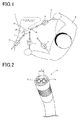
- Fig. 1 is illustrative of how to carry out laparoscopic surgery using various medical instruments.
- laparoscopic surgery there are plural holes cut open in the abdomen or the like of a patient.
- various medical instruments such as an endoscope 2, forceps 2' and (electric) scalpels are inserted through the patient's body for viewing and treatment of an affected site A while checking up on images taken through the endoscope 2.
- This laparoscopic surgery is less invasive of patients because of requiring less incision area.
- Fig. 1 illustrates that the endoscope 2 is being inserted through the trocar 1a while the forceps 2' are being inserted through the trocar 1d.
- an imaging unit 28 mounted to show images taken by the imaging unit 28 on a display unit such as a monitor.
- the endoscope 2 is manipulated by an assistant called the "scopist", and the subject of interest is imaged on the basis of an instruction from a surgeon B.
- the forceps 2' are provided at the distal end part with a distal-end gripper 26 that works as an end effector, and the surgeon B (user) manipulates the forceps 2' to open or close or otherwise handle the distal-end gripper 26 for surgical operation of the affected site A. With laparoscopic surgery, it is thus possible for the surgeon B to use the forceps 2' for surgical operation while viewing images taken through the endoscope 2.
- distance measurement is often carried out so as to get a more precise grasp of what is going on in the interior of the patient's body.
- Distance measurement may be implemented by various methods, one of which makes use of a compound-eye endoscope, viz., an endoscope having two imaging units so as to measure a distance from the distal end of the endoscope to a subject of interest pursuant to the stereoscopic measurement principle.
- Fig. 2 shows one specific state of the distal end of such a compound-eye endoscope 2.
- the compound-eye endoscope 2 includes two imaging units OL and OR on its distal end part at a distance d (parallax) between them. With the compound-eye endoscope 2, it is possible not only to measure a distance to the subject of interest but also to obtain a three-dimensional viewing of the subject of interest.
- Fig. 3 is illustrative of the principle of stereoscopic measurement using the compound-eye endoscope 2.
- the subject of interest imaged through the imaging units OL and OR (focal length f) will be put in positions XL and XR on images PL and PR.
- the distance (parallax) between both the imaging units OL and OR as d.
- a distance Z from the compound-eye endoscope 2 to the subject of interest may be computed from Equation (1) according the principle of triangulation.
- Z d ⁇ f / XL ⁇ XR
- the present invention relates to distance measurement using a monocular (single imaging unit) endoscope.
- Fig. 4 is illustrative of the construction and control configuration of the endoscope according to one embodiment of the invention.
- Fig. 4(A) shows how the endoscope 2 is connected to a controller 3. The same goes for Fig. 4(B) with the exception that the controller 3 is not shown.
- the endoscope 2 serving as a medical instrument includes a first shaft 24 connected to the gripper member 27 and a second shaft 24b that is rotationally connected to the first shaft 24a by way of a moving joint 25.
- the distal end of the second shaft 24b is provided with the imaging unit 28 serving as an end effector.
- a single (monocular) imaging unit 28 is used. An image taken by the imaging unit 28 is produced out to the controller 3, and the surgeon may operate a display unit such as a monitor 4 to display the image on it, thereby viewing what is going on in the patient's body.
- the gripper member 27 is provided with a direction input part 21a and a distance-measurement instruction part 21b, by which the surgeon may adjust the direction (of the axis of sighting) of the imaging unit 28 and give an instruction about distance measurement.
- a driver 22 is driven on the basis of operation of the direction input part 21a.
- the amount of driving by the driver 22 is transmitted by way of a wire or other means to the moving joint 25 for its rotation.
- the imaging direction (of the axis of sighting) of the imaging unit 28 provided at the distal end of the second shaft 24b is adjusted on the basis of the rotation of the moving joint 25. While the moving joint 25 is shown in the form of two-dimensional operation on the sheet plane, it is to be understood that it may be operated in three-dimensional directions including a direction orthogonal to the sheet plane.
- Insertion of the endoscope 2 as explained above through the trocar 1 that communicates the patient's body surface with the interior of the body makes it possible to view the interior of the body in laparoscopic surgery.
- medical instruments such as endoscope 2 are used in states detected by various sensors that are included in the trocar 1. For this reason, the construction of the trocar 1 including various sensors is illustrated in Figs. 5 , 6 and 7 .
- Fig. 5 is illustrative of the external appearance of the trocar 1 that may be used with the medical system according to one embodiment of the invention.
- the trocar 1 described herein includes an upper housing 111, a lower housing 112 and a cylindrical tube 113.
- the upper housing 111 is provided with an insertion path 115 for insertion of various medical instruments.
- the cylindrical tube 113 is inserted through the patient's body.
- a medical instrument inserted from the insertion path 115 goes through the lower housing 112 and cylindrical tube 113, and is inserted from the lower end of the cylindrical tube 113 into the patient's body for the purpose of viewing the interior of the patient's body or surgical treatments in the patient's body.
- the upper housing 111 there are various sensors provided for detection of the states of the trocar 1 and the medical instrument inserted from the insertion path 115. Signals produced out of various sensors are sent out to the controller 3 by way of a cable 114. Note here that the cable 114 has another function of feeding power supply to various sensors. While communication between the sensors and the controller 3 may be of such a wired type, it is to be understood that use of wireless communication and battery-activated driving may lead to elimination of the cable 114 from the trocar 1.
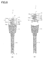
- Fig. 6 is a sectional view of the internal construction of the trocar 1 according to one embodiment of the invention. While the upper housing 111 is shown to have the insertion path 115 as explained with reference to Fig. 5 , it is to be noted that a brown part from the insertion path 115 down to the lower end of the cylindrical tube 113 is a communicating section through which various medical instruments are to be inserted.
- the upper housing 111 and the lower housing 112 may be coupled to or decoupled from each other by means of coupler members 116R and 116L, each in a clip form.
- coupler members 116R and 116L each in a clip form.
- the upper 111 and lower housing 112 are coupled together as depicted in Fig.
- the upper housing 111 may be removed out from the lower housing 112 as depicted in Fig. 6(B) . This facilitates cleaning, disinfection or replacement of the cylindrical tube 113 as well as maintenance of the upper housing 111 including various sensors.
- the trocar 1 may be designed as a single housing in which the upper housing 111 is integral with the lower housing 112.
- the upper housing 111 includes various sensors (for instance, a trocar sensor 12) inside.
- the trocar sensor 12 includes a tilt angle detection sensor 121, an amount-of-advanceable/retractable-movement detection sensor 122, and an amount-of-rotation detection sensor 123.
- the tilt angle detection sensor 121 is provided for detecting the tilt angle of the trocar 1, that is, in which direction the trocar 1 turns with respect to a reference coordinate system.
- the reference coordinate system here is the one that is defined relative to a fixed object such as a patient or the ground, and various sensors inclusive of an acceleration sensor may be used for the tilt angle detection sensor 121.
- the acceleration sensor may detect an acceleration applied thereon to detect in which direction the trocar 1 turns, that is, the tilt angle of the trocar 1 with respect to the reference coordinate system.
- the amount-of-advanceable/retractable-movement detection sensor 122 is provided for detection of the amount of advanceable/retractable movement of a medical instrument inserted through the trocar 1 in its insertion direction (in the vertical direction in Fig. 6 ).
- a surgeon such as a physician inserts or withdraws a medical instrument through the trocar 1 to operate and move the medical instrument within the patient's body to an unerring position.
- the amount-of-advanceable/retractable-movement detection sensor 122 it is possible to detect the insertion position of the medical instrument relative to the trocar 1 in the form of the amount of advanceable/retractable movement.
- the amount-of-advanceable/retractable-movement detection sensor 122 detects the amount of movement parallel with that center axis C in the form of the amount of advanceable/retractable movement.
- the amount-of-advanceable/retractable-movement detection sensor 122 is made up of a combined amount-of-advanceable/retractable-movement detection roller 122a and photosensor 122b.
- the amount-of-rotation detection sensor 123 is provided for detection of the amount of rotation of a medical instrument that rotates in association with operation as by a surgeon. By rotational operation about the center axis C of a medical instrument inserted through the insertion path 115, it is possible to change the direction of the end effector mounted at the distal end of the medical instrument within the patient's body.
- the amount-of-rotation detection sensor 123 detects this amount of rotation so that in which direction the end effector of the medical instrument turns can be detected.
- the amount-of-rotation detection sensor 123 is made up of a combined amount-of-rotation detection roller 123a and photosensor 123b.
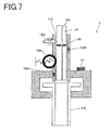
- Fig. 7 is a schematic view of the construction of the trocar sensor 12.
- Fig. 7 is illustrative in schematic of the construction of the trocar sensor 12 disposed within the trocar 1 of Fig. 6 , showing that the first shaft 24 of the medical instrument is being inserted through the trocar 1. Note here that Fig. 7 does not show an end effector and so on attached to the distal end of the medical instrument.
- the trocar 1 will be fixed near to the patient's body surface, but it will rotate pivotally with a certain point as reference in association with operation of the medical instrument.
- the tilt angle detection sensor 121 fixed to the housing of the trocar 1 is capable of detecting pivotal rotation of the trocar 1 to detect the direction of the trocar 1, i.e., the direction of the medical instrument in the reference coordinate system.
- the amount-of-advanceable/retractable-movement detection sensor 122 is made up of a combined amount-of-advanceable/retractable-movement detection roller 122a and photosensor 122b as explained with reference to Fig. 6 .
- the amount-of-advanceable/retractable-movement detection roller 122a has a direction vertical to the plane of Fig. 7 as a rotary axis.
- This amount-of-advanceable/retractable-movement detection roller 122a is biased by a resilient member like a spring toward the insertion path 115, and comes into contact with the surface of the medical instrument (the first shaft 24) inserted through the insertion path 115 to convert the amount of advanceable/retractable movement of the medical instrument into its amount of rotation.
- the rotary axis of the amount-of-advanceable/retractable-movement detection roller 122a is provided with an encoder to produce out the amount of rotation of the amount-of-advanceable/retractable-movement detection roller 122a in the form of the amount of advanceable/retractable movement.
- the photosensor 122b facing in the insertion path 115 is provided so as to calibrate the amount of advanceable/retractable movement (set it to the initial value).
- This photosensor 122b is capable of detecting a position-of-advanceable/retractable-movement detection mark 241 positioned on the medical instrument (the first shaft 24 or the like) to calibrate the amount of advanceable/retractable movement detected by the amount-of-advanceable/retractable-movement detection roller 122a.
- the amount of advanceable/retractable movement will be calibrated (set to the initial value) each time the position-of-advanceable/retractable-movement detection mark 241 is just past the photosensor 122b, making sure detection of the exact amount of advanceable/retractable movement of the medical instrument relative to the trocar 1.
- the amount-of-rotation detection sensor 123 is made up of a combined amount-of-rotation detection roller 123a and photosensor 123b.
- the amount-of-rotation detection roller 123a has a rotary axis turning in the vertical direction of Fig. 7 .
- This amount-of-rotation detection roller 123a is biased by a resilient member like a spring toward the insertion path 115, and comes into contact with the surface of the medical instrument (the first shaft 24) inserted through the insertion path 115 to convert the amount of rotation of the medical instrument into the amount of rotation of the amount-of-rotation detection roller 123a.
- the contact surface of the amount-of-rotation detection roller 123a is preferably provided with a member (like a bearing) that does not interfere with movement of the medical instrument in the insertion direction.
- the rotary axis of the amount-of-rotation detection roller 123a is provided with an encoder that produces out the amount of rotation of the amount-of-rotation detection roller 123a in the form of the amount of rotation of the medical instrument.
- the photosensor 123b facing in the insertion path 115 is provided so as to calibrate the amount of rotation (set it to the initial value).
- this photosensor 123b is capable of detecting a position-of-rotation detection mark 242 provided on the medical instrument (the first shaft 24 or the like) to calibrate the amount of rotation detected by the amount-of-rotation detection roller 123a.
- trocar sensor disposed in the trocar 1 has been explained, it is to be understood that various sensor forms may be used to set up the trocar sensor.
- a mechanical sensor using rollers is used for detection of the amount of advanceable/retractable movement or rotation
- an optical sensor used with a laser mouth and capable of detecting the amount and direction of surface movement may also be used for detection of the amount of advanceable/retractable movement or rotation.
- the amount of advanceable/retractable movement and rotation may be detected with a single optical sensor.
- the direction or the direction and position of the medical instrument inserted through the patient's body are required.
- various sensors are mounted in the trocar 1 to detect such parameters so that the trocar 1 is easily handled.
- the direction or the direction and position of the medical instrument may be detected using sensors located outside of the trocar 1.
- the tilt angle detection sensor 121 located within the trocar 1 may be mounted directly on the medical instrument side.
- Fig. 8 is illustrative of how the interior of the body is viewed by way of the medical system according to one embodiment of the invention.
- the medical system (endoscope system) explained here is constructed mainly of the aforementioned endoscope 2, trocar 1 and controller 3.
- the trocar sensor 12 may be used to detect various states of the endoscope 2 such as its position and amount of movement; however, it is to be noted that the trocar sensor 12 is not always necessary and may be provided as desired.
- the trocar 1 is being inserted through the patient's body surface B to communicate the patient's body surface B with the interior of the body by way of the insertion path 115.
- the endoscope 2 inserted so that the interior of the patient's body may be viewed through the imaging unit 28 mounted at the distal end.
- An image taken by the imaging unit 28 is produced out to the controller 3 where it is displayed on the monitor 4 as a display unit.
- the direction input part 21a is operated by the operator of the endoscope 2 such as the scopist to rotate the moving joint 25 for variation of the axis of sighting (imaging direction) of the imaging unit 28.
- the operator may then adjust the position of the gripper member 27 and use the direction input part 21a to vary the axis of sighting of the imaging unit 28 thereby turning the viewing direction toward the subject of interest Pt.
- the position of the gripper member 27 adjusted by the operator may be detected by the trocar sensor 12 as a detection part.
- Information indicative of the state of the endoscope 2 detected by the trocar sensor 12 is produced out to the controller 3.
- the trocar sensor 12 is capable of detecting the amount of insertion Lb of the endoscope 2 and the tilt angle ⁇ b that the first shaft 24a forms with the reference coordinate system such as a horizontal plane, and the amount-of-rotation detection roller 123a is capable of detecting the angle of rotation of the endoscope 2 or the like.
- the controller 3 is also capable of detecting the control angle ⁇ j of the moving joint 25. With such arrangement it is possible to have a grasp of the state of the endoscope 2.
- the gripper member 27 is further provided with the distance-measurement instruction part 21b that may be operated by the operator to measure the distance to the subject of interest.
- Fig. 9 is a block diagram for the control configuration of the medical system according to the embodiment described herein.
- the medical system is constructed mainly of the endoscope 2 and controller 3, and external hardware includes various sensors attached to the trocar 1 and the monitor 4 for displaying an image from the imaging unit 28 on it, and so on.
- the trocar 1 includes a trocar sensor 12 including the tilt angle detection sensor 121, amount-of-advanceable/retractable-movement detection sensor 122 and amount-of-rotation detection sensor 123, and a communication unit 13.
- the endoscope 2 includes an operation input unit 21 including the direction input part 21a explained with reference to Fig. 4 , a distance-measurement instruction part 21b and a driver 22.
- the driver 22 is a member such as a motor for rotation of the moving joint 25 of the endoscope 2.
- the driver 22 may be designed such that the moving joint 25 is directly rotated or, alternatively, it is indirectly rotated by a wire or thread.
- the trocar 1 and endoscope 2 are connected to the controller 3.
- the controller 3 includes a control unit 31 made up of a CPU and so on, and a memory 32 serving as a storage unit.
- the memory 32 may store various programs running on the medical system, and various signals and data necessary for running the programs.
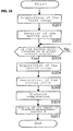
- Fig. 10 is a control flowchart for the endoscope system according to the embodiment described herein. Processing shown in this control flowchart is implemented on the controller 3 during laparoscopic surgery. As the processing gets started, the controller 3 determines whether or not a distance-measurement instruction is entered from the distance-measurement instruction part 21b (S101). When there is no distance-measurement instruction (S101: No) or, in another parlance, when the endoscope 2 is in a normal processing mode, an image taken by the imaging unit 28 is produced out to the monitor 4 where a screen display is produced (S108).
- S101 the distance-measurement instruction part 21b
- distance-measurement processing steps S102 to S107 get started.
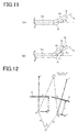
- the operation of the endoscope 2 upon distance measurement is shown in Fig. 11 .
- the first image is first taken from the imaging unit 28 (S102).
- the state of the distal end of the endoscope 2 upon acquisition of the first image is depicted in Fig. 11(A) showing that the axis of sighting E1 of the imaging unit 28 is tilting at a joint angle ⁇ 1 with respect to the center axis of the first shaft 24a.
- the controller 3 drives the driver 22 on the basis of the preset amount of distance-measurement control to start rotation of the moving joint 25 (S103).
- Fig. 11(B) shows the operation of the endoscope 2 at the time of distance measurement.
- the moving joint 25 being placed at the joint angle ⁇ 2 is determined on the basis of control of the driver 22 (S104: Yes). That is, when there is the state of Fig. 11(B) appearing, the controller 3 acquires the second image from the imaging unit 28 (S105), after which there is restoration processing implemented to restore the moving joint 25 back to a state before the start of the distance-measurement processing, i.e., the state of Fig.
- the distance to the subject of interest is computed on the basis of the first image and the second image taken in S102 and S105.
- the first image and the second image have a parallax for the reason that they are acquired by the rotation of the moving joint 25.
- the first image and the second image may be used to compute the distance to the subject of interest, included in the first image and the second image, in accordance with a principle similar to the stereoscope measurement principle explained with reference to Fig. 3 .
- correction for rotation coordinate system transformation
- Fig. 12 shows the pseudo-stereoscopic measurement principle underlying the endoscope according to the embodiment described herein.
- a coordinate system at the time when the first image P1 is taken is given by xz and a coordinate system at the time when the second image is taken is given by x'z'.
- the x'z' and xz coordinate systems will tilt by the amount of distance-measurement control ⁇ 3.
- the radius of rotation R is a value already known from the construction of the endoscope 2 (e.g., positional relations between the moving joint 25 and the imaging unit 28).
- the distance from the imaging unit 28 to the subject of interest will then be able to be computed on the basis of a principle similar the stereoscopic measurement principle explained with reference to Fig. 3 .
- the subject of interest may be computed with respect to an appropriate location included in both the first image and the second image. For instance, when the center position of the first image is selected as the location of interest, the computed distance could be displayed as a figure on the image appearing on the display unit 4 through the controller 3. Further, the subject of interest may be selected by the operator or, alternatively, the distances to a plurality of locations of interest may be computed. In that case, the distances could be displayed as contour lines on the images. The computed distance may also be used as proximity warning rather than being displayed. When the computed distance is less than a given value, the monitor 4 or other means such as a speaker may be used to warn that the endoscope is too close to the inner wall in the interior of the body.
- the measured distance information may also be used for the purpose of varying the control parameters for the moving joint depending on distance.
- a coefficient multiplied by the amount of instruction from the direction input part may be made small, and at a far distance, the coefficient may be made large.
- distance-measurement processing steps (S102 to S107) get started on the basis of the distance-measurement instruction entered by the operator, it is to be understood that they may be implemented periodically or automatically in association with a given operation, etc. during use of the endoscope 2; that is, the distance-measurement instruction may be entered not only by the operation of the operator but also from the controller 3.
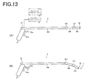
- Fig. 13 is illustrative of the construction and control configuration of the endoscope according to another embodiment of the invention. While the endoscope 2 according to the aforesaid embodiment is designed to use one moving joint 25 to vary the imaging direction (axis of sighting) of the imaging unit 28 as explained with reference to Fig. 4 , it is to be appreciated that the endoscope 2 shown in Fig. 13 is embodied in such a way as to include two moving joints 25a and 25b that are movable in a plurality of positions. As depicted in Fig.
- a first shaft 24a and a second shaft 24b are connected together in such a way as to be rotatable about the first moving joint 25a, and the second shaft 24b and a third shaft 24c are connected together in such a way as to be rotatable about the second joint 25b.
- An imaging unit is mounted on the distal end of the third shaft 24c. Operation of a direction input part 21a permits for rotation of the first moving joint 25a and the second moving joint 25b to vary the axis-of-sighting direction of the imaging unit 28. Rotational control of the first 25a and the second joint 25b may be individually implemented at varying direction input parts.
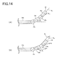
- Fig. 14 is illustrative of how the operation of the distal end part of the endoscope 2 explained with reference to Fig. 13 is controlled upon distance-measurement processing.
- Fig. 14(A) shows a state of the distal end part just before the start of distance-measurement processing, in which state the second shaft 24b is tilting at a joint angle ⁇ 1 of the first moving joint 25a with respect to the first shaft 24a, and the third shaft 24c is tilting at a joint angle ⁇ 2 of the second moving joint 25b with respect to the second shaft 24b.
- a distance-measurement instruction As a distance-measurement instruction is entered in the state of Fig. 14(A) , it causes the controller 3 to rotate the first moving joint 25a and the second moving joint 25b as shown in Fig. 14(B) on the basis of an amount of distance-measurement control.
- the amount of distance-measurement control is set at ⁇ 3 so that the first moving joint 25a is adjusted to a position from which ⁇ 3 is subtracted and the second moving joint 25b to a position to which ⁇ 3 is added. Therefore, the axes of sighting of the imaging unit 28 will move parallel by a distance d (corresponding to the parallax) as indicated by an axis of sighting E1 and an axis of sighting E2.
- the first image is taken in the state of the axis of sighting E1 and the second image is taken in the state of the axis of sighting E2, it causes the coordinate systems at the time when both the images are taken to match substantially or get parallel.
- This dispenses with the pseudo-stereoscopic distance-measurement principle for rotating systems as explained with reference to Fig. 12 , easing off burdens on position computation processing and preventing errors occurring from rotation correction processing. Note here that such parallel movement of the axes of sighting may be implemented not just by use of plural moving joints but also in other various forms.
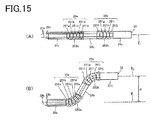
- Fig. 15 is illustrative of the construction and control configuration of the endoscope according to a further embodiment of the invention.
- two moving joints 25a and 25b are used as in Fig. 14 , but they have different arrangements.
- the first moving joint 25a includes, and is made up of, a plurality of articulating pieces 251a to 251d inside.
- Each articulating piece 251a to 251d is configured such that it is thicker in the vicinity of the center and gets thinner with a distance from the center.
- Such articulating pieces 251a to 251d are joined together whereby the first moving joint 25a is bendable as shown in Fig. 15(B) .
- the first moving joint 25a and the second moving joint 25b are provided with protective parts 252a and 252b (each formed of a rubber film as an example).
- the protective parts 252a and 252b conform in shape with the associated moving joints 25a and 25b depending on their moving state thereby preventing ingress of moisture inside or deposition of dirt.
- the rotation (bending) of the first moving joint 25a may be controlled by pulling control wires 29b fixed to the second shaft 24b side by way of the driver 22. As any one of the control wires 29b shown is pulled, it causes the second shaft 24b to be bent in the direction of the pulled wire 29b. While there are two control wires 29b shown in the form of a plane view, it is to be appreciated that more control wires 29b are required so as to achieve three-dimensional bending. The same goes for the second moving joint 25b: the rotation of the third shaft 24c may be controlled by pulling a control wire 29c.
- the axes of sighting may be moved parallel as in Fig. 14 .
- the first moving joint 25a and the second moving joint 25b are rotated from the state of Fig. 15(A) to the state of Fig. 15(B) , it permits for parallel movement of both the axes of sighting E1 and E2, which in turn gives rise to a parallax d between E1 and E2.
- the parallax d is exaggeratedly shown in Fig. 15 for the purpose of explaining the operation of each moving joint 25a, 25b, it is to be noted that the parallax d may be kept small by decreasing the amount of rotation of each moving joint 25a, 25b in the distance-measurement processing.
- the timing of when the second image is taken is set at the time when the moving joint 25 is rotated by the amount of distance-measurement control.
- the control using the control wire 29 explained with reference to Fig. 15 it is to be noted that there might possibly be a time lag between the driving operation of the driver 22 (pulling of the control wire 29) and the operation of the moving joint 25.
- How to determine the image for distance measurement (the second image) according the embodiment described herein is shown in Fig. 16 .
- Fig. 16(A) is illustrative of how images are taken in the vicinity of the distal end part of the endoscope 2 upon distance-measurement processing.
- Fig. 16(B) shows images P1 to P4 taken upon distance-measurement processing. Note here that there is no need for displaying the images of Fig. 16(B) on the monitor 4.
- objects O1 and O2 that are being taken.
- the moving joint 25 As the moving joint 25 is rotated upon distance-measurement processing, it will cause the objects O1 and O2 to move relative to the already taken image, giving rise to an optical flow between the taken images.
- the moving joint 25 In a state where the moving joint 25 reaches the amount of distance-measurement control, the amount of rotation of the moving joint 25 becomes small, so does the optical flow, or it otherwise reaches 0 (equilibrium).
- such inter-image characteristics are used to process a plurality of images taken during the rotation of the moving joint 25 upon distance-measurement processing. It is thus possible to determine the second image best for distance measurement, i.e., an image at the time when the moving joint 25 is rotated by the amount of distance-measurement control.
- the second image best for distance measurement, i.e., an image at the time when the moving joint 25 is rotated by the amount of distance-measurement control.
- the image P3 in equilibrium where the optical flow is zero is determined as the second image.
- the predetermined value i.e., data stored in the memory 32 of the controller 3 are employed as the amount of distance-measurement control used for distance-measuring processing.
- the amount of distance-measurement control is adjusted depending on an already known rough distance to the subject of interest so much so that the precision of an actual distance measurement can be improved.
- Equation (1) d ⁇ f / Z
- Equation (2) teaches that with the (parallax) d fixed, the longer the distance Z, the smaller Xm is: because XL-XR gets small, the precision with which distance computation is implemented by applying image processing to the taken image would go low.
- the parallax d By setting the parallax d at a large value in the case where there is a large Z, it is thus possible to improve the precision with which distance is computed.
- there is a small distance Z on the other hand, there is little loss of the precision with which distance is computed by setting the parallax d at a small value, and the parallax d can be smaller so that the amount of rotation of the moving joint 25 upon distance-measurement processing becomes smaller and the time taken by distance-measurement processing gets shorter.
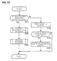
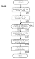
- Figs. 17 , 18 and 19 are control flowcharts for the endoscope system in the case where there is a variable amount of distance-measurement control.
- the distance-measurement instruction shown in Fig. 17 (S101) and the normal processing steps (S107, S108 and S109) of the endoscope 2 will not be explained because of being similar to those in the control flowchart explained with reference to Fig. 10 .
- distance-measurement trial processing (S200) is implemented prior to distance-measurement processing (S300) for computation of an actual distance.
- a rough distance to the subject of interest is computed in this distance-measurement trial processing (S200) thereby determining the amount of distance-measurement control used in the distance-measurement processing (S300).
- the amount of distance-measurement control may be determined not only by such distance-measurement trial processing (S200) but also on the basis of the distance measured by the previous distance-measurement processing.
- the amount of distance-measurement control may be determined by distance-measurement trial processing using an infrared sensor, an ultrasonic sensor or other like sensor mounted on the distal end of the endoscope 2.
- Fig. 18 is a flowchart for the distance-measurement trial processing (S200) according to the embodiment described herein.
- the distance-measurement trial processing (S200) gets started in response to a distance-measurement instruction (S101: Yes) entered, the first image is taken by the imaging unit 28 (S201).
- the controller 3 starts to rotate the moving joint 25 by the predetermined control amount (S202).
- the moving joint 25 is found to be rotated by the predetermined control amount (S203: Yes), it allows for taking and acquisition of the second image (S204), followed by implementation of restoration processing to restore the moving joint 25 back to its original state (S205).
- Fig. 19 is illustrative of the distance-measurement processing (S300) using the amount of distance-measurement control ⁇ set in this distance-measurement trial processing (S200).
- the distance-measurement processing (S300) gets started, the first image is taken by the imaging unit 28 (S301).
- the controller 3 starts to rotate the moving joint 25 (S302) based on the amount of distance-measurement control ⁇ set in the distance-measurement trial processing (S200).
- the moving joint 25 is found to be rotated by the amount of distance-measurement control ⁇ (S303: Yes)
- the second image is taken (S304), and the moving joint 25 is restored back to its original state (S305).
- the endoscope system including the endoscope 2 and controller 3 has been explained, it is to be noted that the endoscope system according to the embodiment described herein further includes in the trocar 1 a trocar sensor 12 capable of detecting various states of the endoscope 2, as explained with reference to Fig. 8 , etc. As described just below, the embodiment described herein includes a trocar sensor 12 or the like that is capable of detecting various states of the endoscope 2. Note here that the invention disclosed herein is not limited to the trocar sensor 12; various modes capable of detecting various states of the endoscope 2 such as the provision of an acceleration sensor on the endoscope 2 side may be relied up.
- the distance-measurement processing steps (S102 to S106) explained with reference to Fig. 10 are based on the assumption that there is no movement but the rotation of the moving joint 25. In actual applications, however, the endoscope 2 may possibly shake or otherwise rock during the distance-measurement processing because it is operated while the gripper member 27 is grasped by the operator. In the embodiment described herein, various pieces of information produced out of the trocar sensor 12 are used and the amount of movement of the imaging unit 28 measured during the distance-measurement processing is used. While taking into consideration the amount of movement of the endoscope 2 between a point of time when the first image is taken and a point of time when the second image is taken, distance computation is carried out in the distance-measurement processing thereby improving the precision of the computed distance.
- various states of the endoscope 2 to be detected include a tilt angle detected by the tilt angle detection sensor 121, an amount of advanceable/retractable movement detected by the amount-of-advanceable/retractable-movement detection sensor 122, and an amount of rotation detected by the amount-of-rotation detection sensor 123.
- Such various states are used to acquire the amount of movement of the endoscope 2 resulting from shaking or rocking during the distance-measurement processing, i.e., the amount of movement of the imaging unit 28, and with that amount of movement in consideration, distance computation can be carried out to bring the precision up.
- Fig. 20 is illustrative of distance-measurement processing that is implemented in follow-up imaging processing using the trocar sensor 12.
- the follow-up imaging processing is designated and implemented by the operator or the like for rotation of the moving joint 25 without recourse to the operation of the direction input part 21a unlike the normal processing for rotation of the moving joint 25 in response to the operation of the direction input part 21a.
- a reference surface St that is defined by the surface of the affected site is set on a follow-up reference surface, and the moving joint 25 is driven and controlled such that the axis of sighting of the imaging unit 28 is at a given angle (here at an orthogonal angle) with respect to that reference surface St.
- the direction of axis of sighting of the imaging unit 28 is determined on the basis of a sensor signal produced out of the trocar sensor 12. Note here that in Fig.
- a sign ⁇ b stands for an angle that the first shaft 24a forms with a reference coordinate system C
- a sign ⁇ j indicates a control angle of the moving joint 25 in the follow-up processing
- P1 and P2 stand for points of intersection of the direction of axis of sighting of the imaging unit 28 with the reference surface St.
- the controller 3 determines a direction in which the first shaft 24a turns to rotate the moving joint 25 by the driver 22 such that the direction of axis of sighting of the imaging unit 28 is set at a given angle (here an orthogonal angle) with respect to the reference surface St. While the operation of the moving joint 25 is explained in the form of a two-dimensional movement on the sheet plane with reference to Fig. 20 , it is to be understood that the follow-up imaging processing is also well compatible with a three-dimensional movement including a direction orthogonal to the sheet plane.
- the follow-up mode is designated in the mode input part (not shown) of the input unit 21, it permits the controller 3 to implement the follow-up imaging processing for controlling the driver 22 on the basis of a sensor signal produced out of the trocar sensor 12 instead of control of the driver 22 (angle adjustment of the moving joint 25) on the basis of an operating signal from the direction input part 21a.
- the follow-up reference surface set on the reference coordinate system is stored, and the driver 22 is controlled in the follow-up imaging processing such that on the basis of the sensor signal and follow-up reference surface, the imaging unit 28 of the endoscope 2 has a given angular relation to the follow-up surface.
- the input unit 21 may include an setting input part through which the follow-up reference is set by the operation of the operator or, alternatively, the follow-up reference surface may be set on the basis of the results of detection by various sensors such as images taken by the endoscope 2.
- the surface of the affected site is set on the reference surface St; however, the reference surface may be a virtual one rather than a real one.
- the imaging unit 28 may be set at a given tilt angle rather than the orthogonal angle with respect to the reference surface St.
- the reference surface St may be a curved one rather than the plane. For instance, the curved surface of the affected site taken by another endoscope inserted through the interior of the patient's body apart from the medical instrument 2 may be set as the reference surface St.
- the distance from the imaging unit 28 to the reference surface St may be computed using the amount of movement between the first image taken in the state of Fig. 20(A) and the second image taken in the state of Fig. 20(B) , and between Figs. 20(A) and 20(B) acquired by the trocar sensor 12.
- this processing there may be distance computation implemented in which the first image is taken at the time when the distance-measurement instruction is entered, and the second image is taken under the conditions that the endoscope 2 moves from the first image by the predetermined amount of movement.
- the first image is taken at the time when the distance-measurement instruction is entered, and the second image is taken after the elapse of a given time to sense the amount of movement of the endoscope 2 in a time period from the acquisition of the first image to the acquisition of the second image.
- the distance to the subject of interest is computed using the first image and the second image, and the amount of movement of the endoscope 2 between at the times when both the images are acquired.
- the distance-measurement processing at the time of such follow-up imaging processing it is possible to implement distance computation with higher precision at the time of distance-measurement processing because the axes of the imaging unit 28 are kept parallel with each other before and after the movement of the endoscope 2.
- Fig. 21 shows an embodiment wherein there is the moving joint located outside the body.
- the endoscope 2 does not include any moving joint, and instead include a trocar position control unit 5 for making the position of the trocar 1 variable.
- This trocar position control unit 5 includes a base 53 placed on the floor surface lying outside the body, etc., a plurality of arms 51a to 51e, and a plurality of moving joints 52a to 52d for making a rotatable connection between the adjacent ones of the arms 51a to 51e.
- the moving joints 52a to 52d are each capable of rotation by a driver such as a motor.
- the driver adapted to rotate each of the moving joints 52a to 52d is driven by control of the controller 3.
- the trocar 1 may be rotated about a point of insertion of the trocar 1 (a position on the body surface B through which the trocar 1 is to be inserted) by control by the trocar position control unit 5, and operated while being less invasive of the body surface B of the patient.
- the controller 3 controls the trocar position control unit 5 to rotate the trocar 1 about the point of insertion of the trocar 1 so that there is a change in the angle of insertion of the endoscope 2, which in turn causes a change in the direction of axis of sighting of the imaging unit 28 mounted on the distal end of the endoscope 2.
- the endoscope system it is thus possible to rotate the moving joints 52a to 52d for movement of the axis of sighting of the endoscope 2 as is the case with the aforesaid embodiments.
- the amount of control of the moving joints 52a to 52d in the trocar position control unit 5 it is possible to acquire the tilt angle, amount of advanceable/retractable movement and amount of rotation of the endoscope 2.
- the distance to the subject of interest may be computed on the basis of the amount of distance-measurement control depending on the thus acquired tilt angle, amount of advanceable/retractable movement and amount of rotation of the endoscope 2, the first image taken before the implementation of movement processing and the second image taken during the implementation of movement processing.
Landscapes
- Health & Medical Sciences (AREA)
- Life Sciences & Earth Sciences (AREA)
- Engineering & Computer Science (AREA)
- Surgery (AREA)
- Physics & Mathematics (AREA)
- General Health & Medical Sciences (AREA)
- Medical Informatics (AREA)
- Biomedical Technology (AREA)
- Heart & Thoracic Surgery (AREA)
- Molecular Biology (AREA)
- Animal Behavior & Ethology (AREA)
- Public Health (AREA)
- Veterinary Medicine (AREA)
- Pathology (AREA)
- Biophysics (AREA)
- Nuclear Medicine, Radiotherapy & Molecular Imaging (AREA)
- Radiology & Medical Imaging (AREA)
- Optics & Photonics (AREA)
- Signal Processing (AREA)
- General Physics & Mathematics (AREA)
- Oral & Maxillofacial Surgery (AREA)
- Dentistry (AREA)
- Multimedia (AREA)
- Computer Vision & Pattern Recognition (AREA)
- Robotics (AREA)
- Theoretical Computer Science (AREA)
- Electromagnetism (AREA)
- Remote Sensing (AREA)
- Radar, Positioning & Navigation (AREA)
- Quality & Reliability (AREA)
- Human Computer Interaction (AREA)
- Endoscopes (AREA)
- Instruments For Viewing The Inside Of Hollow Bodies (AREA)
- Measurement Of Optical Distance (AREA)
Abstract
Description
- The present invention relates to a method of measuring distance by an endoscope that is inserted through the body of a patient for surgical operation to view the interior of the patient's body as well as an endoscope system.
- Currently, a trocar is inserted from the body surface of a patient through the interior of the body and various medical instruments are inserted through the trocar to carry out laparoscopic surgery for various treatments and medical examinations in the interior of the body. Although this laparoscopic surgery is less invasive of patients because of making do with a limited incision in the body surface of the patient, it is still required to improve on the visibility of an endoscope and the operability of medical instruments because of the need for performing operations while viewing the interior of the patient's body by way of the endoscope. For laparoscopic surgery, it is required to check up on the interior states of the patient's body with images from the endoscope, and distance measurement is implemented by the endoscope as one method of obtaining detailed information from such images.
-
Patent Literature 1 discloses an endoscope apparatus for measuring the amount of insertion of an endoscope to measure a distance between the endoscope and a subject of interest from a feature point position of the subject on the images before and after insertion. -
Patent Literature 2 discloses an endoscope system for measuring the amount of movement of an endoscope to compare an image before movement with an image after movement for distance measurement. -
- [Patent Literature 1]
JP(A)3-80824 - [Patent Literature 2] Japanese Patent No.
3041420 - With the endoscope apparatus for measurement disclosed in
Patent Literature 1, it is impossible to perform precise distance measurement upon rotation of an optical axis because only the amount of advanceable/retractable movement is corrected, and with the endoscope system disclosed inPatent Literature 2, it is difficult to carry out distance measurement with stabilized precision because computation is performed based on the amount of manually operated movement, resulting in lack of amount-of-movement and direction reproducibility. An object of the present invention is to provide a method of measuring distance by an endoscope and an endoscope system making sure distance measurement with stabilized precision. - To accomplish the objects, the present invention provides a method of measuring distance by an endoscope that makes an axis of sighting of an imaging unit movable by means of a moving joint, wherein:
- imaging processing and distance-measurement processing are changeably implementable,
- the imaging processing controls the moving joint on the basis of an direction instruction from an input part to move the axis of sighting of the imaging unit and produce out an image taken by the imaging unit, and
- the distance-measurement processing controls the moving joint on the basis of an amount of distance-measurement control to implement movement processing for moving the axis of sighting of the imaging unit and acquire a first image taken before implementation of the movement processing and a second image taken during implementation of the movement processing so that, on the basis of the first image, the second image and the amount of distance-measurement control, a distance to a subject of interest is computed.
- In one embodiment of the method of measuring distance by an endoscope according to the invention, the distance-measurement processing is adapted to implement restoration processing for restoring the moving joint back to a state before the movement after implementation of the movement processing.
- In one embodiment of the method of measuring distance by an endoscope according to the invention, the distance-measurement processing is adapted to change an angle of the axis of sighting on the basis of the amount of distance-measurement control.
- In one embodiment of the method of measuring distance by an endoscope according to the invention, the distance-measurement processing is adapted to implement parallel movement of the axes of sighting of the imaging unit on the basis of the amount of distance-measurement control.
- In one embodiment of the method of measuring distance by an endoscope according to the invention, the distance-measurement processing is adapted to determine the second image from a plurality of images taken during implementation of the movement processing.
- In one embodiment of the method of measuring distance by an endoscope according to the invention, the distance-measurement processing makes use of an amount of distance-measurement control depending on a distance that is computed by distance-measurement trial processing.
- In one embodiment of the method of measuring distance by an endoscope according to the invention, the distance-measurement processing makes use of, in addition to the first image, the second image and the amount of distance-measurement control, an amount of movement of the endoscope detected by a sensor to compute a distance to a subject of interest.
- The present invention also provides a method of measuring distance by an endoscope that makes an axis of sighting of an imaging unit movable by means of a moving joint, wherein:
- follow-up imaging processing and distance-measurement processing are implementable,
- the follow-up imaging processing controls the moving joint such that the axis of sighting of the imaging unit has a given angle with respect to a preset follow-up reference surface, and produce out an image taken by the imaging unit, and
- the distance-measurement processing makes use of a first image and a second image taken during the follow-up imaging processing, and an amount of movement of the endoscope between a point of time when the first image is taken and a point of time when the second image is taken to compute a distance to a subject of interest.
- In one embodiment of the method of measuring distance by an endoscope according to the invention, the moving joint is movable in a plurality of positions.
- Further, the present invention provides an endoscope system, including an imaging unit, a moving joint, an input unit, and a control unit, wherein:
- the imaging unit is capable of acquiring an image by imaging,
- the moving joint makes an axis of sighting of the imaging unit movable on the basis of an instruction from the control unit,
- the input unit is capable of entering an instruction about a direction of the moving joint,
- the control unit is capable of changeably implementing the imaging processing and distance-measurement processing,
- the imaging processing controls the moving joint on the basis of the direction instruction from the input unit to move the axis of sighting of the imaging unit and produce out an image taken by the imaging unit, and
- the distance-measurement processing controls the moving joint on the basis of an amount of distance-measurement control to implement movement processing for moving the axis of sighting of the imaging unit and acquire a first image taken before implementation of the movement processing and a second image taken during implementation of the movement processing so that a distance to a subject of interest is computed on the basis of the first image, the second image and the amount of distance-measurement control.
- According to the inventive method of measuring distance by an endoscope and the inventive endoscope system, the movement of the moving joint for moving the direction of the axes of sighting of the imaging unit is used to acquire the first and second images, and a distance to a subject of interest is computed on the basis of the thus acquired first and second images and the amount of distance-measurement control equivalent to the amount of actuation of the moving joint so that the distance may be measured in the interior of the patient's body with stabilized precision.
-
-
Fig. 1 is illustrative of how to carry out laparoscopic surgery using medical instruments (such as an endoscope and forceps). -
Fig. 2 shows one illustrative state of the distal end of a compound-eye endoscope. -
Fig. 3 is illustrative of the principle of stereoscopic measurement using a compound-eye endoscope. -
Fig. 4 is illustrative of the construction and control configuration of the endoscope according to one embodiment of the invention. -
Fig. 5 is illustrative of the external appearance of the trocar according to one embodiment of the invention. -
Fig. 6 is illustrative of the internal construction of the trocar according to one embodiment of the invention. -
Fig. 7 is illustrative in schematic of the construction of the trocar sensor according to one embodiment of the invention. -
Fig. 8 is illustrative of how the interior of the body is viewed by way of the medical system according to one embodiment of the invention. -
Fig. 9 is a block diagram for the control configuration for the medical system according to one embodiment of the invention. -
Fig. 10 is a control flowchart for the medical system according to one embodiment of the invention. -
Fig. 11 is illustrative of the actuation upon distance measurement of the endoscope according to one embodiment of the invention. -
Fig. 12 is illustrative of the principle of pseudo-stereoscopic distance measurement using the endoscope according to one embodiment of the invention. -
Fig. 13 is illustrative of the construction and control configuration of the endoscope according to another embodiment of the invention. -
Fig. 14 is illustrative of the actuation upon distance measurement of the endoscope according to one embodiment of the invention. -
Fig. 15 is illustrative of the construction and control configuration of the endoscope according to another embodiment of the invention. -
Fig. 16 is illustrative of how to determine images for distance measurement according to one embodiment of the invention. -
Fig. 17 is a control flowchart for the medical system according to another embodiment of the invention. -
Fig. 18 is a flowchart for distance-measurement trial processing according to one embodiment of the invention. -
Fig. 19 is a flowchart for distance-measurement processing according to one embodiment of the invention. -
Fig. 20 is illustrative of distance-measurement processing that is implemented upon follow-up imaging processing according to one embodiment of the invention. -
Fig. 21 is illustrative of how the interior of the body is viewed using the medical system according to another embodiment of the invention. -
Fig. 1 is illustrative of how to carry out laparoscopic surgery using various medical instruments. In laparoscopic surgery, there are plural holes cut open in the abdomen or the like of a patient. Then, various medical instruments such as anendoscope 2, forceps 2' and (electric) scalpels are inserted through the patient's body for viewing and treatment of an affected site A while checking up on images taken through theendoscope 2. This laparoscopic surgery is less invasive of patients because of requiring less incision area. - In laparoscopic surgery, tubes called trocars (channels) 1a to 1d are inserted in openings cut open in the patient's body wall, and various medical instruments are inserted through the patient via the trocars 1a to 1d.
Fig. 1 illustrates that theendoscope 2 is being inserted through the trocar 1a while the forceps 2' are being inserted through thetrocar 1d. On the distal end part of theendoscope 2, there is animaging unit 28 mounted to show images taken by theimaging unit 28 on a display unit such as a monitor. Usually, theendoscope 2 is manipulated by an assistant called the "scopist", and the subject of interest is imaged on the basis of an instruction from a surgeon B. The forceps 2' are provided at the distal end part with a distal-end gripper 26 that works as an end effector, and the surgeon B (user) manipulates the forceps 2' to open or close or otherwise handle the distal-end gripper 26 for surgical operation of the affected site A. With laparoscopic surgery, it is thus possible for the surgeon B to use the forceps 2' for surgical operation while viewing images taken through theendoscope 2. - In such laparoscopic surgery, distance measurement is often carried out so as to get a more precise grasp of what is going on in the interior of the patient's body. Distance measurement may be implemented by various methods, one of which makes use of a compound-eye endoscope, viz., an endoscope having two imaging units so as to measure a distance from the distal end of the endoscope to a subject of interest pursuant to the stereoscopic measurement principle.
Fig. 2 shows one specific state of the distal end of such a compound-eye endoscope 2. The compound-eye endoscope 2 includes two imaging units OL and OR on its distal end part at a distance d (parallax) between them. With the compound-eye endoscope 2, it is possible not only to measure a distance to the subject of interest but also to obtain a three-dimensional viewing of the subject of interest. -
Fig. 3 is illustrative of the principle of stereoscopic measurement using the compound-eye endoscope 2. Here take the axis of sighting of the compound-eye endoscope 2 as the z-axis, and an axis orthogonal thereto as the xy-plane (with the y-axis left out of here). The subject of interest imaged through the imaging units OL and OR (focal length f) will be put in positions XL and XR on images PL and PR. Here take the distance (parallax) between both the imaging units OL and OR as d. A distance Z from the compound-eye endoscope 2 to the subject of interest may be computed from Equation (1) according the principle of triangulation.
- By use of the images PL and PR taken through the compound-
eye endoscope 2 including the two imaging units OL and OR at its distal end, it is thus possible to compute a distance to the subject of interest at a suitable place in the taken images. However, such compound-eye endoscope 2 must have two imaging units OL and OR mounted at its distal end, resulting in an increase in its diameter. Unlike such a conventional distance measurement method, the present invention relates to distance measurement using a monocular (single imaging unit) endoscope. -
Fig. 4 is illustrative of the construction and control configuration of the endoscope according to one embodiment of the invention.Fig. 4(A) shows how theendoscope 2 is connected to acontroller 3. The same goes forFig. 4(B) with the exception that thecontroller 3 is not shown. Theendoscope 2 serving as a medical instrument includes afirst shaft 24 connected to thegripper member 27 and asecond shaft 24b that is rotationally connected to thefirst shaft 24a by way of a moving joint 25. The distal end of thesecond shaft 24b is provided with theimaging unit 28 serving as an end effector. In the embodiment described herein, a single (monocular)imaging unit 28 is used. An image taken by theimaging unit 28 is produced out to thecontroller 3, and the surgeon may operate a display unit such as amonitor 4 to display the image on it, thereby viewing what is going on in the patient's body. - The
gripper member 27 is provided with adirection input part 21a and a distance-measurement instruction part 21b, by which the surgeon may adjust the direction (of the axis of sighting) of theimaging unit 28 and give an instruction about distance measurement. As depicted inFig. 4(B) , adriver 22 is driven on the basis of operation of the direction inputpart 21a. The amount of driving by thedriver 22 is transmitted by way of a wire or other means to the moving joint 25 for its rotation. The imaging direction (of the axis of sighting) of theimaging unit 28 provided at the distal end of thesecond shaft 24b is adjusted on the basis of the rotation of the moving joint 25. While the moving joint 25 is shown in the form of two-dimensional operation on the sheet plane, it is to be understood that it may be operated in three-dimensional directions including a direction orthogonal to the sheet plane. - Insertion of the
endoscope 2 as explained above through thetrocar 1 that communicates the patient's body surface with the interior of the body makes it possible to view the interior of the body in laparoscopic surgery. In a certain aspect of the embodiment described herein, medical instruments such asendoscope 2 are used in states detected by various sensors that are included in thetrocar 1. For this reason, the construction of thetrocar 1 including various sensors is illustrated inFigs. 5 ,6 and7 . -
Fig. 5 is illustrative of the external appearance of thetrocar 1 that may be used with the medical system according to one embodiment of the invention. Thetrocar 1 described herein includes anupper housing 111, alower housing 112 and acylindrical tube 113. Theupper housing 111 is provided with aninsertion path 115 for insertion of various medical instruments. Thecylindrical tube 113 is inserted through the patient's body. A medical instrument inserted from theinsertion path 115 goes through thelower housing 112 andcylindrical tube 113, and is inserted from the lower end of thecylindrical tube 113 into the patient's body for the purpose of viewing the interior of the patient's body or surgical treatments in the patient's body. - Within the
upper housing 111 there are various sensors provided for detection of the states of thetrocar 1 and the medical instrument inserted from theinsertion path 115. Signals produced out of various sensors are sent out to thecontroller 3 by way of acable 114. Note here that thecable 114 has another function of feeding power supply to various sensors. While communication between the sensors and thecontroller 3 may be of such a wired type, it is to be understood that use of wireless communication and battery-activated driving may lead to elimination of thecable 114 from thetrocar 1. -
Fig. 6 is a sectional view of the internal construction of thetrocar 1 according to one embodiment of the invention. While theupper housing 111 is shown to have theinsertion path 115 as explained with reference toFig. 5 , it is to be noted that a brown part from theinsertion path 115 down to the lower end of thecylindrical tube 113 is a communicating section through which various medical instruments are to be inserted. Theupper housing 111 and thelower housing 112 may be coupled to or decoupled from each other by means ofcoupler members trocar 1, the upper 111 andlower housing 112 are coupled together as depicted inFig. 6(A) , and for cleaning or other purposes, theupper housing 111 may be removed out from thelower housing 112 as depicted inFig. 6(B) . This facilitates cleaning, disinfection or replacement of thecylindrical tube 113 as well as maintenance of theupper housing 111 including various sensors. Note here that thetrocar 1 may be designed as a single housing in which theupper housing 111 is integral with thelower housing 112. - In the
trocar 1 according to the embodiment described herein, theupper housing 111 includes various sensors (for instance, a trocar sensor 12) inside. In the embodiment described herein, thetrocar sensor 12 includes a tiltangle detection sensor 121, an amount-of-advanceable/retractable-movement detection sensor 122, and an amount-of-rotation detection sensor 123. The tiltangle detection sensor 121 is provided for detecting the tilt angle of thetrocar 1, that is, in which direction thetrocar 1 turns with respect to a reference coordinate system. The reference coordinate system here is the one that is defined relative to a fixed object such as a patient or the ground, and various sensors inclusive of an acceleration sensor may be used for the tiltangle detection sensor 121. The acceleration sensor may detect an acceleration applied thereon to detect in which direction thetrocar 1 turns, that is, the tilt angle of thetrocar 1 with respect to the reference coordinate system. - The amount-of-advanceable/retractable-
movement detection sensor 122 is provided for detection of the amount of advanceable/retractable movement of a medical instrument inserted through thetrocar 1 in its insertion direction (in the vertical direction inFig. 6 ). As already explained with reference toFig. 1 , a surgeon such as a physician inserts or withdraws a medical instrument through thetrocar 1 to operate and move the medical instrument within the patient's body to an unerring position. With the amount-of-advanceable/retractable-movement detection sensor 122, it is possible to detect the insertion position of the medical instrument relative to thetrocar 1 in the form of the amount of advanceable/retractable movement.Fig. 6(A) shows the center axis C of thetrocar 1 in the insertion direction by a dashed line. The amount-of-advanceable/retractable-movement detection sensor 122 detects the amount of movement parallel with that center axis C in the form of the amount of advanceable/retractable movement. In the embodiment described herein, the amount-of-advanceable/retractable-movement detection sensor 122 is made up of a combined amount-of-advanceable/retractable-movement detection roller 122a andphotosensor 122b. - The amount-of-
rotation detection sensor 123 is provided for detection of the amount of rotation of a medical instrument that rotates in association with operation as by a surgeon. By rotational operation about the center axis C of a medical instrument inserted through theinsertion path 115, it is possible to change the direction of the end effector mounted at the distal end of the medical instrument within the patient's body. The amount-of-rotation detection sensor 123 detects this amount of rotation so that in which direction the end effector of the medical instrument turns can be detected. In the embodiment described herein, the amount-of-rotation detection sensor 123 is made up of a combined amount-of-rotation detection roller 123a andphotosensor 123b. - While the internal construction of the
trocar 1 has been explained, it is to be understood that thetrocar sensor 12 disposed within thetrocar 1 sends a detection signal out to thecontroller 3 by way of acommunication unit 13 not shown inFig. 6 . Actuation of thetrocar sensor 12 in the embodiment described herein is now explained with reference toFig. 7 that is a schematic view of the construction of thetrocar sensor 12.Fig. 7 is illustrative in schematic of the construction of thetrocar sensor 12 disposed within thetrocar 1 ofFig. 6 , showing that thefirst shaft 24 of the medical instrument is being inserted through thetrocar 1. Note here thatFig. 7 does not show an end effector and so on attached to the distal end of the medical instrument. - There is some margin given to the diameter of the
insertion path 115 for thetrocar 1 in such a way as to receive the insertion part of the medical instrument such as thefirst shaft 24. Thetrocar 1 will be fixed near to the patient's body surface, but it will rotate pivotally with a certain point as reference in association with operation of the medical instrument. The tiltangle detection sensor 121 fixed to the housing of thetrocar 1 is capable of detecting pivotal rotation of thetrocar 1 to detect the direction of thetrocar 1, i.e., the direction of the medical instrument in the reference coordinate system. - In the embodiment described herein, the amount-of-advanceable/retractable-
movement detection sensor 122 is made up of a combined amount-of-advanceable/retractable-movement detection roller 122a andphotosensor 122b as explained with reference toFig. 6 . The amount-of-advanceable/retractable-movement detection roller 122a has a direction vertical to the plane ofFig. 7 as a rotary axis. This amount-of-advanceable/retractable-movement detection roller 122a is biased by a resilient member like a spring toward theinsertion path 115, and comes into contact with the surface of the medical instrument (the first shaft 24) inserted through theinsertion path 115 to convert the amount of advanceable/retractable movement of the medical instrument into its amount of rotation. The rotary axis of the amount-of-advanceable/retractable-movement detection roller 122a is provided with an encoder to produce out the amount of rotation of the amount-of-advanceable/retractable-movement detection roller 122a in the form of the amount of advanceable/retractable movement. In the embodiment described herein, thephotosensor 122b facing in theinsertion path 115 is provided so as to calibrate the amount of advanceable/retractable movement (set it to the initial value). Thisphotosensor 122b is capable of detecting a position-of-advanceable/retractable-movement detection mark 241 positioned on the medical instrument (thefirst shaft 24 or the like) to calibrate the amount of advanceable/retractable movement detected by the amount-of-advanceable/retractable-movement detection roller 122a. Upon advanceable/retractable movement of the medical instrument through theinsertion path 115, therefore, the amount of advanceable/retractable movement will be calibrated (set to the initial value) each time the position-of-advanceable/retractable-movement detection mark 241 is just past thephotosensor 122b, making sure detection of the exact amount of advanceable/retractable movement of the medical instrument relative to thetrocar 1. - As already explained with reference to
Fig. 6 , the amount-of-rotation detection sensor 123 according to the embodiment described herein is made up of a combined amount-of-rotation detection roller 123a andphotosensor 123b. The amount-of-rotation detection roller 123a has a rotary axis turning in the vertical direction ofFig. 7 . This amount-of-rotation detection roller 123a is biased by a resilient member like a spring toward theinsertion path 115, and comes into contact with the surface of the medical instrument (the first shaft 24) inserted through theinsertion path 115 to convert the amount of rotation of the medical instrument into the amount of rotation of the amount-of-rotation detection roller 123a. Note here that the contact surface of the amount-of-rotation detection roller 123a is preferably provided with a member (like a bearing) that does not interfere with movement of the medical instrument in the insertion direction. The rotary axis of the amount-of-rotation detection roller 123a is provided with an encoder that produces out the amount of rotation of the amount-of-rotation detection roller 123a in the form of the amount of rotation of the medical instrument. In the embodiment described herein, thephotosensor 123b facing in theinsertion path 115 is provided so as to calibrate the amount of rotation (set it to the initial value). As with the amount-of-advanceable/retractable-movement detection sensor 122, thisphotosensor 123b is capable of detecting a position-of-rotation detection mark 242 provided on the medical instrument (thefirst shaft 24 or the like) to calibrate the amount of rotation detected by the amount-of-rotation detection roller 123a. - While the trocar sensor disposed in the
trocar 1 has been explained, it is to be understood that various sensor forms may be used to set up the trocar sensor. In the embodiment described herein, for instance, a mechanical sensor using rollers is used for detection of the amount of advanceable/retractable movement or rotation, but an optical sensor used with a laser mouth and capable of detecting the amount and direction of surface movement may also be used for detection of the amount of advanceable/retractable movement or rotation. In that case, the amount of advanceable/retractable movement and rotation may be detected with a single optical sensor. For the medical system according to the embodiment described herein, the direction or the direction and position of the medical instrument inserted through the patient's body are required. In the embodiment described herein, various sensors are mounted in thetrocar 1 to detect such parameters so that thetrocar 1 is easily handled. It is here to be noted that the direction or the direction and position of the medical instrument may be detected using sensors located outside of thetrocar 1. For instance, the tiltangle detection sensor 121 located within thetrocar 1 may be mounted directly on the medical instrument side. -
Fig. 8 is illustrative of how the interior of the body is viewed by way of the medical system according to one embodiment of the invention. The medical system (endoscope system) explained here is constructed mainly of theaforementioned endoscope 2,trocar 1 andcontroller 3. In the embodiment described herein, thetrocar sensor 12 may be used to detect various states of theendoscope 2 such as its position and amount of movement; however, it is to be noted that thetrocar sensor 12 is not always necessary and may be provided as desired. - The
trocar 1 is being inserted through the patient's body surface B to communicate the patient's body surface B with the interior of the body by way of theinsertion path 115. Through theinsertion path 115 in thetrocar 1 there is theendoscope 2 inserted so that the interior of the patient's body may be viewed through theimaging unit 28 mounted at the distal end. An image taken by theimaging unit 28 is produced out to thecontroller 3 where it is displayed on themonitor 4 as a display unit. Thedirection input part 21a is operated by the operator of theendoscope 2 such as the scopist to rotate the moving joint 25 for variation of the axis of sighting (imaging direction) of theimaging unit 28. The operator may then adjust the position of thegripper member 27 and use the direction inputpart 21a to vary the axis of sighting of theimaging unit 28 thereby turning the viewing direction toward the subject of interest Pt. - In the embodiment described herein, the position of the
gripper member 27 adjusted by the operator may be detected by thetrocar sensor 12 as a detection part. Information indicative of the state of theendoscope 2 detected by thetrocar sensor 12 is produced out to thecontroller 3. Thetrocar sensor 12 is capable of detecting the amount of insertion Lb of theendoscope 2 and the tilt angle θb that thefirst shaft 24a forms with the reference coordinate system such as a horizontal plane, and the amount-of-rotation detection roller 123a is capable of detecting the angle of rotation of theendoscope 2 or the like. On the basis of the operation of the direction inputpart 21a, thecontroller 3 is also capable of detecting the control angle θj of the moving joint 25. With such arrangement it is possible to have a grasp of the state of theendoscope 2. Thegripper member 27 is further provided with the distance-measurement instruction part 21b that may be operated by the operator to measure the distance to the subject of interest. -
Fig. 9 is a block diagram for the control configuration of the medical system according to the embodiment described herein. The medical system is constructed mainly of theendoscope 2 andcontroller 3, and external hardware includes various sensors attached to thetrocar 1 and themonitor 4 for displaying an image from theimaging unit 28 on it, and so on. - The
trocar 1 includes atrocar sensor 12 including the tiltangle detection sensor 121, amount-of-advanceable/retractable-movement detection sensor 122 and amount-of-rotation detection sensor 123, and acommunication unit 13. Theendoscope 2 includes anoperation input unit 21 including the direction inputpart 21a explained with reference toFig. 4 , a distance-measurement instruction part 21b and adriver 22. Thedriver 22 is a member such as a motor for rotation of the movingjoint 25 of theendoscope 2. Thedriver 22 may be designed such that the moving joint 25 is directly rotated or, alternatively, it is indirectly rotated by a wire or thread. - The
trocar 1 andendoscope 2 are connected to thecontroller 3. Thecontroller 3 includes acontrol unit 31 made up of a CPU and so on, and amemory 32 serving as a storage unit. Thememory 32 may store various programs running on the medical system, and various signals and data necessary for running the programs. - How to measure distance using such a medical system (endoscope system) is now explained.
Fig. 10 is a control flowchart for the endoscope system according to the embodiment described herein. Processing shown in this control flowchart is implemented on thecontroller 3 during laparoscopic surgery. As the processing gets started, thecontroller 3 determines whether or not a distance-measurement instruction is entered from the distance-measurement instruction part 21b (S101). When there is no distance-measurement instruction (S101: No) or, in another parlance, when theendoscope 2 is in a normal processing mode, an image taken by theimaging unit 28 is produced out to themonitor 4 where a screen display is produced (S108). Here when there is an operation (direction instruction) of the direction inputpart 21a (S109: Yes), there is the moving joint 25 rotated by thedriver 22 in association with that operation (S110). Through the processing steps S108 to S110 it is thus possible to view the interior of the patient's body as is the case with theconventional endoscope 2. - When there is a distance-measurement instruction entered from the distance-
measurement instruction part 21b (S101: Yes), on the other hand, distance-measurement processing steps S102 to S107 get started. The operation of theendoscope 2 upon distance measurement is shown inFig. 11 . In the distance-measurement processing, the first image is first taken from the imaging unit 28 (S102). The state of the distal end of theendoscope 2 upon acquisition of the first image is depicted inFig. 11(A) showing that the axis of sighting E1 of theimaging unit 28 is tilting at a joint angle θ1 with respect to the center axis of thefirst shaft 24a. Then, thecontroller 3 drives thedriver 22 on the basis of the preset amount of distance-measurement control to start rotation of the moving joint 25 (S103). -
Fig. 11(B) shows the operation of theendoscope 2 at the time of distance measurement. In this example, the amount of distance-measurement control with respect to the joint angle is set at θ3, and thecontroller 3 gets the moving joint 25 rotated from the joint angle θ1 to θ2 (θ2=θ1+θ3). The moving joint 25 being placed at the joint angle θ2 is determined on the basis of control of the driver 22 (S104: Yes). That is, when there is the state ofFig. 11(B) appearing, thecontroller 3 acquires the second image from the imaging unit 28 (S105), after which there is restoration processing implemented to restore the moving joint 25 back to a state before the start of the distance-measurement processing, i.e., the state ofFig. 11(A) (S106). During the rotation of the moving joint 25 in the distance-measurement processing step, it is preferable not to produce the image taken by theimaging unit 28 in the form of a screen display on themonitor 4. During the rotation of the moving joint 25 in the distance-measurement processing step, any image fit for the operator's intension is not obtained; an image taken just before the start of the distance-measurement processing is used in place of any image being taken by theimaging unit 28 so that the operator can view themonitor 4 without feeling a sense of discomfort. Thus, if the restoration processing is implemented to restore theimaging unit 28 back to the original state, it is possible to view a succession of images before and after the distance-measurement processing. - In S107, the distance to the subject of interest is computed on the basis of the first image and the second image taken in S102 and S105. The first image and the second image have a parallax for the reason that they are acquired by the rotation of the moving joint 25. For this reason, the first image and the second image may be used to compute the distance to the subject of interest, included in the first image and the second image, in accordance with a principle similar to the stereoscope measurement principle explained with reference to
Fig. 3 . However, it is preferable that correction for rotation (coordinate system transformation) is carried out because the axis of sighting of theimaging unit 28 has been rotated. -
Fig. 12 shows the pseudo-stereoscopic measurement principle underlying the endoscope according to the embodiment described herein. Suppose now that a coordinate system at the time when the first image P1 is taken is given by xz and a coordinate system at the time when the second image is taken is given by x'z'. The x'z' and xz coordinate systems will tilt by the amount of distance-measurement control θ3. The radius of rotation R, on the other hand, is a value already known from the construction of the endoscope 2 (e.g., positional relations between the moving joint 25 and the imaging unit 28). Therefore, if the amount of distance-measurement control θ3 and radius of rotation R are used for coordinate system transformation for matching the x'z' coordinate system to the xz coordinate system, the distance from theimaging unit 28 to the subject of interest will then be able to be computed on the basis of a principle similar the stereoscopic measurement principle explained with reference toFig. 3 . - The subject of interest may be computed with respect to an appropriate location included in both the first image and the second image. For instance, when the center position of the first image is selected as the location of interest, the computed distance could be displayed as a figure on the image appearing on the
display unit 4 through thecontroller 3. Further, the subject of interest may be selected by the operator or, alternatively, the distances to a plurality of locations of interest may be computed. In that case, the distances could be displayed as contour lines on the images. The computed distance may also be used as proximity warning rather than being displayed. When the computed distance is less than a given value, themonitor 4 or other means such as a speaker may be used to warn that the endoscope is too close to the inner wall in the interior of the body. The measured distance information may also be used for the purpose of varying the control parameters for the moving joint depending on distance. At a near distance, for instance, a coefficient multiplied by the amount of instruction from the direction input part may be made small, and at a far distance, the coefficient may be made large. As a result, the rate of change of the field of view versus input is kept constant even when there is a change in the distance to the subject of interest, resulting likely in improvements in operability. - While the distance-measurement processing steps (S102 to S107) get started on the basis of the distance-measurement instruction entered by the operator, it is to be understood that they may be implemented periodically or automatically in association with a given operation, etc. during use of the
endoscope 2; that is, the distance-measurement instruction may be entered not only by the operation of the operator but also from thecontroller 3. -
Fig. 13 is illustrative of the construction and control configuration of the endoscope according to another embodiment of the invention. While theendoscope 2 according to the aforesaid embodiment is designed to use one moving joint 25 to vary the imaging direction (axis of sighting) of theimaging unit 28 as explained with reference toFig. 4 , it is to be appreciated that theendoscope 2 shown inFig. 13 is embodied in such a way as to include two movingjoints Fig. 13(A) , afirst shaft 24a and asecond shaft 24b are connected together in such a way as to be rotatable about the first moving joint 25a, and thesecond shaft 24b and athird shaft 24c are connected together in such a way as to be rotatable about the second joint 25b. An imaging unit is mounted on the distal end of thethird shaft 24c. Operation of adirection input part 21a permits for rotation of the first moving joint 25a and the second moving joint 25b to vary the axis-of-sighting direction of theimaging unit 28. Rotational control of the first 25a and the second joint 25b may be individually implemented at varying direction input parts. - With the
endoscope 2 including the movingjoints imaging unit 28 may be varied as set out just below in distance-measurement processing.Fig. 14 is illustrative of how the operation of the distal end part of theendoscope 2 explained with reference toFig. 13 is controlled upon distance-measurement processing.Fig. 14(A) shows a state of the distal end part just before the start of distance-measurement processing, in which state thesecond shaft 24b is tilting at a joint angle θ1 of the first moving joint 25a with respect to thefirst shaft 24a, and thethird shaft 24c is tilting at a joint angle θ2 of the second moving joint 25b with respect to thesecond shaft 24b. - As a distance-measurement instruction is entered in the state of
Fig. 14(A) , it causes thecontroller 3 to rotate the first moving joint 25a and the second moving joint 25b as shown inFig. 14(B) on the basis of an amount of distance-measurement control. In this example, the amount of distance-measurement control is set at θ3 so that the first moving joint 25a is adjusted to a position from which θ3 is subtracted and the second moving joint 25b to a position to which θ3 is added. Therefore, the axes of sighting of theimaging unit 28 will move parallel by a distance d (corresponding to the parallax) as indicated by an axis of sighting E1 and an axis of sighting E2. As the first image is taken in the state of the axis of sighting E1 and the second image is taken in the state of the axis of sighting E2, it causes the coordinate systems at the time when both the images are taken to match substantially or get parallel. This dispenses with the pseudo-stereoscopic distance-measurement principle for rotating systems as explained with reference toFig. 12 , easing off burdens on position computation processing and preventing errors occurring from rotation correction processing. Note here that such parallel movement of the axes of sighting may be implemented not just by use of plural moving joints but also in other various forms. - While the two moving
joints Fig. 14 , it is to be appreciated that the moving joint 25 may take various forms.Fig. 15 is illustrative of the construction and control configuration of the endoscope according to a further embodiment of the invention. In the embodiment described herein, two movingjoints Fig. 14 , but they have different arrangements. Here take the first moving joint 25a as an example. The first moving joint 25a includes, and is made up of, a plurality of articulatingpieces 251a to 251d inside. Each articulatingpiece 251a to 251d is configured such that it is thicker in the vicinity of the center and gets thinner with a distance from the center. Such articulatingpieces 251a to 251d are joined together whereby the first moving joint 25a is bendable as shown inFig. 15(B) . The first moving joint 25a and the second moving joint 25b are provided withprotective parts protective parts joints - The rotation (bending) of the first moving joint 25a may be controlled by pulling
control wires 29b fixed to thesecond shaft 24b side by way of thedriver 22. As any one of thecontrol wires 29b shown is pulled, it causes thesecond shaft 24b to be bent in the direction of the pulledwire 29b. While there are twocontrol wires 29b shown in the form of a plane view, it is to be appreciated thatmore control wires 29b are required so as to achieve three-dimensional bending. The same goes for the second moving joint 25b: the rotation of thethird shaft 24c may be controlled by pulling acontrol wire 29c. - In such arrangement too, the axes of sighting may be moved parallel as in
Fig. 14 . As the first moving joint 25a and the second moving joint 25b are rotated from the state ofFig. 15(A) to the state ofFig. 15(B) , it permits for parallel movement of both the axes of sighting E1 and E2, which in turn gives rise to a parallax d between E1 and E2. While the parallax d is exaggeratedly shown inFig. 15 for the purpose of explaining the operation of each moving joint 25a, 25b, it is to be noted that the parallax d may be kept small by decreasing the amount of rotation of each moving joint 25a, 25b in the distance-measurement processing. - In the control flowchart explained with reference to
Fig. 10 , the timing of when the second image is taken is set at the time when the moving joint 25 is rotated by the amount of distance-measurement control. However, for instance, in the control using the control wire 29 explained with reference toFig. 15 , it is to be noted that there might possibly be a time lag between the driving operation of the driver 22 (pulling of the control wire 29) and the operation of the moving joint 25. How to determine the image for distance measurement (the second image) according the embodiment described herein is shown inFig. 16 . -
Fig. 16(A) is illustrative of how images are taken in the vicinity of the distal end part of theendoscope 2 upon distance-measurement processing. Referring to four states shown inFig. 16(A), Fig. 16(B) shows images P1 to P4 taken upon distance-measurement processing. Note here that there is no need for displaying the images ofFig. 16(B) on themonitor 4. For an easy-to-understand explanation, reference is made to objects O1 and O2 that are being taken. As the moving joint 25 is rotated upon distance-measurement processing, it will cause the objects O1 and O2 to move relative to the already taken image, giving rise to an optical flow between the taken images. In a state where the moving joint 25 reaches the amount of distance-measurement control, the amount of rotation of the moving joint 25 becomes small, so does the optical flow, or it otherwise reaches 0 (equilibrium). - In the embodiment described herein, such inter-image characteristics are used to process a plurality of images taken during the rotation of the moving joint 25 upon distance-measurement processing. It is thus possible to determine the second image best for distance measurement, i.e., an image at the time when the moving joint 25 is rotated by the amount of distance-measurement control. In the example of
Fig. 16 , there is restoration processing carried out in which the moving joint 25 is restored back to the original state after rotated depending on the amount of distance-measurement control. To this end, the image P3 in equilibrium where the optical flow is zero is determined as the second image. By selection of the second image used for distance measurement out of a plurality of images taken upon distance-measurement processing, it is thus possible to get control over a time lag derived from the driver system for the moving joint 25 or the like. In turn, this enables the second image in the state rotated by the amount of distance-measurement control to be acquired with higher precision, resulting in improvements in precision with which distance is computed. - In the control flowchart explained with reference to
Fig. 10 , presume that the predetermined value, i.e., data stored in thememory 32 of thecontroller 3 are employed as the amount of distance-measurement control used for distance-measuring processing. In the distance-measurement processing by theendoscope 2, there might possibly be a change in the distance to the subject of interest. In the embodiment described herein, the amount of distance-measurement control is adjusted depending on an already known rough distance to the subject of interest so much so that the precision of an actual distance measurement can be improved. - With reference to the schematic view of
Fig. 3 , relations of the distance Z to the subject of interest to the parallax d are now explained. The distance Z to the subject of interest may be represented by Equation (1) explained with reference toFig. 3 . Let XL-XR=Xm.
Equation (1) is rewritten as

- Equation (2) teaches that with the (parallax) d fixed, the longer the distance Z, the smaller Xm is: because XL-XR gets small, the precision with which distance computation is implemented by applying image processing to the taken image would go low. By setting the parallax d at a large value in the case where there is a large Z, it is thus possible to improve the precision with which distance is computed. When there is a small distance Z, on the other hand, there is little loss of the precision with which distance is computed by setting the parallax d at a small value, and the parallax d can be smaller so that the amount of rotation of the moving joint 25 upon distance-measurement processing becomes smaller and the time taken by distance-measurement processing gets shorter.
-
Figs. 17 ,18 and19 are control flowcharts for the endoscope system in the case where there is a variable amount of distance-measurement control. The distance-measurement instruction shown inFig. 17 (S101) and the normal processing steps (S107, S108 and S109) of theendoscope 2 will not be explained because of being similar to those in the control flowchart explained with reference toFig. 10 . In the embodiment described herein, as the distance-measurement instruction (S101: Yes) is entered, distance-measurement trial processing (S200) is implemented prior to distance-measurement processing (S300) for computation of an actual distance. In the embodiment described herein, a rough distance to the subject of interest is computed in this distance-measurement trial processing (S200) thereby determining the amount of distance-measurement control used in the distance-measurement processing (S300). The amount of distance-measurement control may be determined not only by such distance-measurement trial processing (S200) but also on the basis of the distance measured by the previous distance-measurement processing. Alternatively, the amount of distance-measurement control may be determined by distance-measurement trial processing using an infrared sensor, an ultrasonic sensor or other like sensor mounted on the distal end of theendoscope 2. -
Fig. 18 is a flowchart for the distance-measurement trial processing (S200) according to the embodiment described herein. As the distance-measurement trial processing (S200) gets started in response to a distance-measurement instruction (S101: Yes) entered, the first image is taken by the imaging unit 28 (S201). In S202, thecontroller 3 starts to rotate the moving joint 25 by the predetermined control amount (S202). As the moving joint 25 is found to be rotated by the predetermined control amount (S203: Yes), it allows for taking and acquisition of the second image (S204), followed by implementation of restoration processing to restore the moving joint 25 back to its original state (S205). Then, on the basis of the first image acquired in S201 and the second image acquired in S204, a distance to a (representative) position common to both the images is computed (S206), followed by the determination of the amount of distance-measurement control β on the basis of the computed distance (S207). -
Fig. 19 is illustrative of the distance-measurement processing (S300) using the amount of distance-measurement control β set in this distance-measurement trial processing (S200). As the distance-measurement processing (S300) gets started, the first image is taken by the imaging unit 28 (S301). In S302, thecontroller 3 starts to rotate the moving joint 25 (S302) based on the amount of distance-measurement control β set in the distance-measurement trial processing (S200). As the moving joint 25 is found to be rotated by the amount of distance-measurement control β (S303: Yes), the second image is taken (S304), and the moving joint 25 is restored back to its original state (S305). Then, on the basis of the first image taken in S301 and the second image taken in S304, a distance to the subject of interest is computed (S306). With the distance-measurement trial processing according to the embodiment described herein, it is thus possible to bring up the precision with which the distance to the subject of interest is computed in the distance-measurement processing. - While the endoscope system including the
endoscope 2 andcontroller 3 has been explained, it is to be noted that the endoscope system according to the embodiment described herein further includes in the trocar 1 atrocar sensor 12 capable of detecting various states of theendoscope 2, as explained with reference toFig. 8 , etc. As described just below, the embodiment described herein includes atrocar sensor 12 or the like that is capable of detecting various states of theendoscope 2. Note here that the invention disclosed herein is not limited to thetrocar sensor 12; various modes capable of detecting various states of theendoscope 2 such as the provision of an acceleration sensor on theendoscope 2 side may be relied up. - The distance-measurement processing steps (S102 to S106) explained with reference to
Fig. 10 are based on the assumption that there is no movement but the rotation of the moving joint 25. In actual applications, however, theendoscope 2 may possibly shake or otherwise rock during the distance-measurement processing because it is operated while thegripper member 27 is grasped by the operator. In the embodiment described herein, various pieces of information produced out of thetrocar sensor 12 are used and the amount of movement of theimaging unit 28 measured during the distance-measurement processing is used. While taking into consideration the amount of movement of theendoscope 2 between a point of time when the first image is taken and a point of time when the second image is taken, distance computation is carried out in the distance-measurement processing thereby improving the precision of the computed distance. When thetrocar sensor 12 is used as the sensor, various states of theendoscope 2 to be detected include a tilt angle detected by the tiltangle detection sensor 121, an amount of advanceable/retractable movement detected by the amount-of-advanceable/retractable-movement detection sensor 122, and an amount of rotation detected by the amount-of-rotation detection sensor 123. Such various states are used to acquire the amount of movement of theendoscope 2 resulting from shaking or rocking during the distance-measurement processing, i.e., the amount of movement of theimaging unit 28, and with that amount of movement in consideration, distance computation can be carried out to bring the precision up. - In the embodiment of detecting various states of the
endoscope 2 by making use of a sensor such as thetrocar sensor 12, there may be such possible distance-measurement processing implemented as explained below.Fig. 20 is illustrative of distance-measurement processing that is implemented in follow-up imaging processing using thetrocar sensor 12. The follow-up imaging processing is designated and implemented by the operator or the like for rotation of the moving joint 25 without recourse to the operation of the direction inputpart 21a unlike the normal processing for rotation of the moving joint 25 in response to the operation of the direction inputpart 21a. - In the embodiment described herein, a reference surface St that is defined by the surface of the affected site is set on a follow-up reference surface, and the moving joint 25 is driven and controlled such that the axis of sighting of the
imaging unit 28 is at a given angle (here at an orthogonal angle) with respect to that reference surface St. The direction of axis of sighting of theimaging unit 28 is determined on the basis of a sensor signal produced out of thetrocar sensor 12. Note here that inFig. 20 , a sign θb stands for an angle that thefirst shaft 24a forms with a reference coordinate system C, a sign θj indicates a control angle of the moving joint 25 in the follow-up processing, and P1 and P2 stand for points of intersection of the direction of axis of sighting of theimaging unit 28 with the reference surface St. - When there is a movement of the
endoscope 2 from the state ofFig. 20(A) to the state ofFig. 20(B) , the direction of axis of sighting of theimaging unit 28 is maintained orthogonally to the reference surface St in either case. On the basis of a sensor signal detected by thetrocar sensor 12, thecontroller 3 determines a direction in which thefirst shaft 24a turns to rotate the moving joint 25 by thedriver 22 such that the direction of axis of sighting of theimaging unit 28 is set at a given angle (here an orthogonal angle) with respect to the reference surface St. While the operation of the moving joint 25 is explained in the form of a two-dimensional movement on the sheet plane with reference toFig. 20 , it is to be understood that the follow-up imaging processing is also well compatible with a three-dimensional movement including a direction orthogonal to the sheet plane. - Referring to the control configuration of
Fig. 9 , as the follow-up mode is designated in the mode input part (not shown) of theinput unit 21, it permits thecontroller 3 to implement the follow-up imaging processing for controlling thedriver 22 on the basis of a sensor signal produced out of thetrocar sensor 12 instead of control of the driver 22 (angle adjustment of the moving joint 25) on the basis of an operating signal from the direction inputpart 21a. Referring here to thememory 32 of thecontroller 3, the follow-up reference surface set on the reference coordinate system is stored, and thedriver 22 is controlled in the follow-up imaging processing such that on the basis of the sensor signal and follow-up reference surface, theimaging unit 28 of theendoscope 2 has a given angular relation to the follow-up surface. - Referring to the follow-up reference surface used for the follow-up imaging processing, the
input unit 21 may include an setting input part through which the follow-up reference is set by the operation of the operator or, alternatively, the follow-up reference surface may be set on the basis of the results of detection by various sensors such as images taken by theendoscope 2. In this control configuration, the surface of the affected site is set on the reference surface St; however, the reference surface may be a virtual one rather than a real one. Further, theimaging unit 28 may be set at a given tilt angle rather than the orthogonal angle with respect to the reference surface St. Still further, the reference surface St may be a curved one rather than the plane. For instance, the curved surface of the affected site taken by another endoscope inserted through the interior of the patient's body apart from themedical instrument 2 may be set as the reference surface St. - In such follow-up imaging processing, for instance, the distance from the
imaging unit 28 to the reference surface St may be computed using the amount of movement between the first image taken in the state ofFig. 20(A) and the second image taken in the state ofFig. 20(B) , and betweenFigs. 20(A) and 20(B) acquired by thetrocar sensor 12. In this processing, there may be distance computation implemented in which the first image is taken at the time when the distance-measurement instruction is entered, and the second image is taken under the conditions that theendoscope 2 moves from the first image by the predetermined amount of movement. Alternatively, there may be distance computation implemented in which the first image is taken at the time when the distance-measurement instruction is entered, and the second image is taken after the elapse of a given time to sense the amount of movement of theendoscope 2 in a time period from the acquisition of the first image to the acquisition of the second image. - In any control configuration, the distance to the subject of interest is computed using the first image and the second image, and the amount of movement of the
endoscope 2 between at the times when both the images are acquired. In the distance-measurement processing at the time of such follow-up imaging processing, it is possible to implement distance computation with higher precision at the time of distance-measurement processing because the axes of theimaging unit 28 are kept parallel with each other before and after the movement of theendoscope 2. Unlike the aforesaid distance-measurement processing, there is no need for rotating the moving joint 25 for distance-measurement processing, so that a succession of images taken by theimaging unit 28 can continuously be viewed on themonitor 4. - While some embodiments having the moving joint located in the interior of the patient's body as shown in
Fig. 8 have so far been described, it is to be noted that the moving joint may be located externally of the body.Fig. 21 shows an embodiment wherein there is the moving joint located outside the body. In the endoscope system according to the embodiment described herein, theendoscope 2 does not include any moving joint, and instead include a trocarposition control unit 5 for making the position of thetrocar 1 variable. This trocarposition control unit 5 includes a base 53 placed on the floor surface lying outside the body, etc., a plurality ofarms 51a to 51e, and a plurality of movingjoints 52a to 52d for making a rotatable connection between the adjacent ones of thearms 51a to 51e. The movingjoints 52a to 52d are each capable of rotation by a driver such as a motor. The driver adapted to rotate each of the movingjoints 52a to 52d is driven by control of thecontroller 3. - In the endoscope system shown in
Fig. 21 , thetrocar 1 may be rotated about a point of insertion of the trocar 1 (a position on the body surface B through which thetrocar 1 is to be inserted) by control by the trocarposition control unit 5, and operated while being less invasive of the body surface B of the patient. Thecontroller 3 controls the trocarposition control unit 5 to rotate thetrocar 1 about the point of insertion of thetrocar 1 so that there is a change in the angle of insertion of theendoscope 2, which in turn causes a change in the direction of axis of sighting of theimaging unit 28 mounted on the distal end of theendoscope 2. In the endoscope system according to the embodiment described herein, too, it is thus possible to rotate the movingjoints 52a to 52d for movement of the axis of sighting of theendoscope 2 as is the case with the aforesaid embodiments. With the amount of control of the movingjoints 52a to 52d in the trocarposition control unit 5, it is possible to acquire the tilt angle, amount of advanceable/retractable movement and amount of rotation of theendoscope 2. The distance to the subject of interest may be computed on the basis of the amount of distance-measurement control depending on the thus acquired tilt angle, amount of advanceable/retractable movement and amount of rotation of theendoscope 2, the first image taken before the implementation of movement processing and the second image taken during the implementation of movement processing. - While the embodiments according to some aspects of the invention have been described, it is to be appreciated that the invention is in no sense limited to them, and that embodiments obtainable from combinations of them are encompassed in the category of the invention too.
-
- 1: Trocar
- 111: Upper housing
- 112: Lower housing
- 113: Cylindrical tube
- 114: Cable
- 115: Insertion path
- 116: Coupler member
- 12: Trocar sensor
- 121: Tilt angle detection sensor
- 122: Amount-of-advanceable/retractable-movement detection sensor
- 122a: Amount-of-advanceable/retractable -movement detection roller
- 122b: Photosensor
- 123: Amount-of-rotation detection sensor
- 123a: Amount-of-rotation detection roller
- 123b: Photosensor
- 13: Communication unit
- 2: Medical instrument (endoscope)
- 2': Medical instrument (forceps)
- 21: Input unit
- 21a: Direction input part
- 21b: Distance-measurement instruction part,
- 22: Driver
- 24a: First shaft
- 24b: Second shaft
- 24c: Third shaft
- 25: Moving joint
- 25a: First moving joint
- 25b: Second moving joint
- 26: Distal-end gripper member (end effector)
- 28: Imaging unit
- 3: Controller
- 31: Control unit
- 32: Memory
- 4: Monitor
- 5: Trocar position control unit
- 51a to 51e: Arms
- 52a to 52d: Moving joints
- 53: Base
Claims (10)
- A method of measuring distance by an endoscope that makes axes of sighting of an imaging unit movable by means of a moving joint, wherein:imaging processing and distance-measurement processing are changeably implementable,the imaging processing controls the moving joint on the basis of an direction instruction from an input unit to move the axis of sighting of the imaging unit and produce out an image taken by the imaging unit, andthe distance-measurement processing controls the moving joint on the basis of an amount of distance-measurement control to implement movement processing for moving the axis of sighting of the imaging unit and acquire a first image taken before implementation of the movement processing and a second image taken during implementation of the movement processing so that, on the basis of the first image, the second image and the amount of distance-measurement control, a distance to a subject of interest is computed.
- The method of measuring distance by an endoscope according to claim 1,
wherein the distance-measurement processing is adapted to implement restoration processing for restoring the moving joint back to a state before the movement after implementation of the movement processing. - The method of measuring distance by an endoscope according to claim 1,
wherein the distance-measurement processing is adapted to change an angle of the axis of sighting of the imaging unit on the basis of the amount of distance-measurement control. - The method of measuring distance by an endoscope according to claim 1,
wherein the distance-measurement processing is adapted to implement parallel movement of the axes of sighting of the imaging unit on the basis of the amount of distance-measurement control. - The method of measuring distance by an endoscope according to claim 1,
wherein the distance-measurement processing is adapted to determine the second image from a plurality of images taken during implementation of the movement processing. - The method of measuring distance by an endoscope according to claim 1,
wherein the distance-measurement processing makes use of an amount of distance-measurement control depending on a distance that is computed by distance-measurement trial processing. - The method of measuring distance by an endoscope according to claim 1,
wherein the distance-measurement processing makes use of, in addition to the first image, the second image and the amount of distance-measurement control, an amount of movement of the endoscope detected by a sensor to compute a distance to a subject of interest. - A method of measuring distance by an endoscope that makes an axis of sighting of an imaging unit movable by means of a moving joint, comprising:follow-up imaging processing and distance-measurement processing are implementable,wherein;the follow-up imaging processing controls the moving joint such that the axis of sighting of the imaging unit has a given angle with respect to a preset follow-up reference surface, and produce out an image taken by the imaging unit, andthe distance-measurement processing makes use of a first image and a second image taken during the follow-up imaging processing, and an amount of movement of the endoscope between a point of time when the first image is taken and a point of time when the second image is taken to compute a distance to a subject of interest.
- The method of measuring distance by an endoscope according to any one of claims 1 to 8,
wherein the moving joint is movable in a plurality of positions. - An endoscope system comprising:an imaging unit; a moving joint; an input unit; and a control unit,wherein:the imaging unit is capable of acquiring an image by imaging,the moving joint makes an axis of sighting of the imaging unit movable on the basis of an instruction from the control unit,the input unit is capable of entering an instruction about a direction of the moving joint,the control unit is capable of changeably implementing the imaging processing and distance-measurement processing,the imaging processing controls the moving joint on the basis of the direction instruction from the input unit to move the axis of sighting of the imaging unit and produce out an image taken by the imaging unit, andthe distance-measurement processing controls the moving joint on the basis of an amount of distance-measurement control to implement movement processing for moving the axis of sighting of the imaging unit and acquire a first image taken before implementation of the movement processing and a second image taken during implementation of the movement processing so that a distance to a subject of interest is computed on the basis of the first image, the second image and the amount of distance-measurement control.
Applications Claiming Priority (2)
| Application Number | Priority Date | Filing Date | Title |
|---|---|---|---|
| JP2013269274A JP6091410B2 (en) | 2013-12-26 | 2013-12-26 | Endoscope apparatus operating method and endoscope system |
| PCT/JP2014/080347 WO2015098353A1 (en) | 2013-12-26 | 2014-11-17 | Method for measuring distance using endoscope, and endoscope system |
Publications (2)
| Publication Number | Publication Date |
|---|---|
| EP3097838A1 true EP3097838A1 (en) | 2016-11-30 |
| EP3097838A4 EP3097838A4 (en) | 2017-10-25 |
Family
ID=53478228
Family Applications (1)
| Application Number | Title | Priority Date | Filing Date |
|---|---|---|---|
| EP14874391.7A Withdrawn EP3097838A4 (en) | 2013-12-26 | 2014-11-17 | Method for measuring distance using endoscope, and endoscope system |
Country Status (5)
| Country | Link |
|---|---|
| US (1) | US10441146B2 (en) |
| EP (1) | EP3097838A4 (en) |
| JP (1) | JP6091410B2 (en) |
| CN (1) | CN105848552B (en) |
| WO (1) | WO2015098353A1 (en) |
Families Citing this family (33)
| Publication number | Priority date | Publication date | Assignee | Title |
|---|---|---|---|---|
| CN103501678B (en) * | 2011-01-28 | 2017-04-05 | 皇家飞利浦电子股份有限公司 | For the optical sensing of the relative tracking of endoscope |
| EP2738756A1 (en) * | 2012-11-30 | 2014-06-04 | Surgical Science Sweden AB | User interface device for surgical simulation system |
| EP2979619B1 (en) * | 2013-03-29 | 2018-10-31 | FUJIFILM Corporation | Device for endoscopic surgery |
| JP5976924B2 (en) * | 2013-03-29 | 2016-08-24 | 富士フイルム株式会社 | Endoscopic surgical device |
| JP5959723B2 (en) * | 2013-03-29 | 2016-08-02 | 富士フイルム株式会社 | Endoscopic surgical device |
| EP2811479B1 (en) * | 2013-06-07 | 2017-08-02 | Surgical Science Sweden AB | A user interface for a surgical simulation system |
| JP2015107249A (en) * | 2013-12-05 | 2015-06-11 | オリンパス株式会社 | Endoscope control method and endoscope system |
| WO2017081821A1 (en) * | 2015-11-13 | 2017-05-18 | オリンパス株式会社 | Method for estimating state of endoscope |
| TWI597042B (en) | 2016-06-29 | 2017-09-01 | Endoscopic with distance measuring function and distance measuring method | |
| US11992283B2 (en) * | 2017-03-07 | 2024-05-28 | Intuitive Surgical Operations, Inc. | Systems and methods for controlling tool with articulatable distal portion |
| US10709311B2 (en) * | 2017-05-11 | 2020-07-14 | Montane Medical Corporation | Video laryngoscope with monitor stabilization |
| CN107389026B (en) * | 2017-06-12 | 2019-10-01 | 江苏大学 | A kind of monocular vision distance measuring method based on fixed point projective transformation |
| WO2019087745A1 (en) * | 2017-10-31 | 2019-05-09 | パナソニックIpマネジメント株式会社 | Cleaning device and cleaning method |
| JP7228781B2 (en) * | 2017-10-31 | 2023-02-27 | パナソニックIpマネジメント株式会社 | Purification device and purification method |
| JP7115493B2 (en) * | 2017-11-01 | 2022-08-09 | ソニーグループ株式会社 | Surgical arm system and surgical arm control system |
| EP3510925A1 (en) * | 2018-01-10 | 2019-07-17 | Universite Libre De Bruxelles | Endoscopic non-contact measurement device |
| US11229492B2 (en) * | 2018-10-04 | 2022-01-25 | Biosense Webster (Israel) Ltd. | Automatic probe reinsertion |
| WO2020070883A1 (en) | 2018-10-05 | 2020-04-09 | オリンパス株式会社 | Endoscopic system |
| CN109222981B (en) * | 2018-11-21 | 2024-02-27 | 北京大学第三医院 | Measurement marking instrument for laparoscopic surgery |
| CN109602386A (en) * | 2019-02-15 | 2019-04-12 | 沈阳智能机器人国家研究院有限公司 | A kind of illumination laparoscope and its control method |
| CN120514313A (en) * | 2019-03-06 | 2025-08-22 | 诺亚医疗集团公司 | Single-use endoscopes, cannulas, and obturators with integrated vision and lighting |
| WO2020181290A1 (en) * | 2019-03-07 | 2020-09-10 | Procept Biorobotics Corporation | Robotic arms and methods for tissue resection and imaging |
| CN110368077A (en) * | 2019-08-22 | 2019-10-25 | 福建骏格科技有限公司 | Visualize thoracocentesis abdominocentesis drain system |
| US12178519B2 (en) * | 2019-10-18 | 2024-12-31 | Medtech S.A. | Depth control instrument guide for robotic surgery |
| US11071601B2 (en) | 2019-11-11 | 2021-07-27 | Procept Biorobotics Corporation | Surgical probes for tissue resection with robotic arms |
| US11096753B1 (en) | 2020-06-26 | 2021-08-24 | Procept Biorobotics Corporation | Systems and methods for defining and modifying range of motion of probe used in patient treatment |
| US12239293B2 (en) * | 2020-10-02 | 2025-03-04 | Verb Surgical Inc. | Endoscope for sensing trocars, compatible cannulas, instruments and accessories |
| US12433682B2 (en) | 2021-03-03 | 2025-10-07 | Boston Scientific Scimed, Inc. | Measurement markings in distal tip imaging field of view |
| US11627243B2 (en) * | 2021-07-23 | 2023-04-11 | Phaox LLC | Handheld wireless endoscope image streaming apparatus |
| DE102021119481A1 (en) * | 2021-07-27 | 2023-02-02 | Karl Storz Se & Co. Kg | Measuring method and a measuring device |
| US20230087044A1 (en) * | 2021-09-22 | 2023-03-23 | Titan Medical Inc. | Systems, methods, and apparatuses for cleaning a camera during a medical procedure |
| CN114767236B (en) * | 2022-06-24 | 2022-09-02 | 北京微刀医疗科技有限公司 | Light output puncture needle, light-sensitive puncture needle and puncture distance measuring system |
| CN116563525B (en) * | 2023-07-10 | 2023-10-20 | 浙江华诺康科技有限公司 | Endoscope running track indicating method, device, equipment and storage medium |
Family Cites Families (16)
| Publication number | Priority date | Publication date | Assignee | Title |
|---|---|---|---|---|
| JPS60108352A (en) | 1983-11-12 | 1985-06-13 | 電気化学工業株式会社 | Super quick settable cement composition |
| US4895431A (en) * | 1986-11-13 | 1990-01-23 | Olympus Optical Co., Ltd. | Method of processing endoscopic images |
| JP2911894B2 (en) * | 1986-11-13 | 1999-06-23 | オリンパス光学工業株式会社 | Endoscope image capturing method and endoscope apparatus |
| JPH0380824A (en) | 1989-08-22 | 1991-04-05 | Olympus Optical Co Ltd | Measuring endoscope device |
| US5253647A (en) * | 1990-04-13 | 1993-10-19 | Olympus Optical Co., Ltd. | Insertion position and orientation state pickup for endoscope |
| US5347987A (en) * | 1991-04-08 | 1994-09-20 | Feldstein David A | Self-centering endoscope system |
| US5159446A (en) * | 1991-06-21 | 1992-10-27 | Olympus Optical Co., Ltd. | Electronic endoscope system provided with a separate camera controlling unit and motor controlling unit |
| JPH0549599A (en) * | 1991-08-23 | 1993-03-02 | Olympus Optical Co Ltd | Electronic endoscope apparatus |
| JP3347385B2 (en) * | 1992-03-27 | 2002-11-20 | オリンパス光学工業株式会社 | Endoscope image processing device |
| JP3041420B1 (en) * | 1999-01-27 | 2000-05-15 | 工業技術院長 | Endoscope system and recording medium storing control program for detecting depth information of endoscope image |
| US6858005B2 (en) * | 2000-04-03 | 2005-02-22 | Neo Guide Systems, Inc. | Tendon-driven endoscope and methods of insertion |
| US6468203B2 (en) * | 2000-04-03 | 2002-10-22 | Neoguide Systems, Inc. | Steerable endoscope and improved method of insertion |
| JP2003244500A (en) * | 2002-02-13 | 2003-08-29 | Pentax Corp | Stereo image pickup device |
| US20040199053A1 (en) * | 2003-04-01 | 2004-10-07 | Scimed Life Systems, Inc. | Autosteering vision endoscope |
| JP4588369B2 (en) | 2004-06-18 | 2010-12-01 | 株式会社トプコン | Imaging apparatus and imaging method |
| EP1607716A3 (en) | 2004-06-18 | 2012-06-20 | Topcon Corporation | Model forming apparatus and method, and photographing apparatus and method |
-
2013
- 2013-12-26 JP JP2013269274A patent/JP6091410B2/en active Active
-
2014
- 2014-11-17 CN CN201480070843.7A patent/CN105848552B/en active Active
- 2014-11-17 EP EP14874391.7A patent/EP3097838A4/en not_active Withdrawn
- 2014-11-17 WO PCT/JP2014/080347 patent/WO2015098353A1/en not_active Ceased
-
2016
- 2016-06-24 US US15/191,685 patent/US10441146B2/en active Active
Also Published As
| Publication number | Publication date |
|---|---|
| JP6091410B2 (en) | 2017-03-08 |
| CN105848552A (en) | 2016-08-10 |
| US10441146B2 (en) | 2019-10-15 |
| JP2015123201A (en) | 2015-07-06 |
| EP3097838A4 (en) | 2017-10-25 |
| US20160302653A1 (en) | 2016-10-20 |
| WO2015098353A1 (en) | 2015-07-02 |
| CN105848552B (en) | 2018-08-07 |
Similar Documents
| Publication | Publication Date | Title |
|---|---|---|
| US10441146B2 (en) | Method of measuring distance by an endoscope, and endoscope system | |
| US20240261047A1 (en) | Systems and methods for offscreen indication of instruments in a teleoperational medical system | |
| US10419680B2 (en) | Endoscope system and method of controlling endoscope system | |
| EP3025658B1 (en) | Medical system and medical instrument control | |
| EP3108795B1 (en) | Endoscope system and endoscope control process | |
| US10441132B2 (en) | Method of controlling endoscopes, and endoscope system | |
| CN113645919A (en) | Medical arm system, control device, and control method | |
| US20160213436A1 (en) | Medical system and method of controlling medical treatment tools | |
| CN104394751B (en) | Robot system | |
| EP3111878A1 (en) | Surgery system and method of avoiding interference with medical instrument | |
| KR20210069542A (en) | Surgical assistant system and method using virtual surgical instruments | |
| US12419719B2 (en) | Camera apparatus for coordinated operation with surgical tools | |
| US20250302278A1 (en) | Endoscope system, control device, control method, and storage medium | |
| US9943213B2 (en) | Medical image processing apparatus generating a three-dimensional image of a medical device superposed over a three-dimensional image of a preoperative structure of an object |
Legal Events
| Date | Code | Title | Description |
|---|---|---|---|
| PUAI | Public reference made under article 153(3) epc to a published international application that has entered the european phase |
Free format text: ORIGINAL CODE: 0009012 |
|
| 17P | Request for examination filed |
Effective date: 20160718 |
|
| AK | Designated contracting states |
Kind code of ref document: A1 Designated state(s): AL AT BE BG CH CY CZ DE DK EE ES FI FR GB GR HR HU IE IS IT LI LT LU LV MC MK MT NL NO PL PT RO RS SE SI SK SM TR |
|
| AX | Request for extension of the european patent |
Extension state: BA ME |
|
| DAX | Request for extension of the european patent (deleted) | ||
| A4 | Supplementary search report drawn up and despatched |
Effective date: 20170922 |
|
| RIC1 | Information provided on ipc code assigned before grant |
Ipc: A61B 17/34 20060101ALI20170918BHEP Ipc: A61B 1/00 20060101AFI20170918BHEP Ipc: A61B 90/00 20160101ALN20170918BHEP Ipc: A61B 5/107 20060101ALI20170918BHEP Ipc: A61B 1/005 20060101ALI20170918BHEP Ipc: A61B 5/00 20060101ALI20170918BHEP Ipc: A61B 5/06 20060101ALI20170918BHEP Ipc: A61B 1/313 20060101ALI20170918BHEP Ipc: A61B 34/20 20160101ALI20170918BHEP Ipc: G01C 3/08 20060101ALI20170918BHEP Ipc: A61B 1/045 20060101ALI20170918BHEP |
|
| GRAP | Despatch of communication of intention to grant a patent |
Free format text: ORIGINAL CODE: EPIDOSNIGR1 |
|
| STAA | Information on the status of an ep patent application or granted ep patent |
Free format text: STATUS: GRANT OF PATENT IS INTENDED |
|
| RIC1 | Information provided on ipc code assigned before grant |
Ipc: A61B 5/107 20060101ALI20190319BHEP Ipc: A61B 1/313 20060101ALI20190319BHEP Ipc: A61B 5/06 20060101ALI20190319BHEP Ipc: A61B 1/00 20060101AFI20190319BHEP Ipc: A61B 34/20 20160101ALI20190319BHEP Ipc: A61B 17/34 20060101ALI20190319BHEP Ipc: A61B 5/00 20060101ALI20190319BHEP Ipc: G01C 3/08 20060101ALI20190319BHEP Ipc: A61B 90/00 20160101ALN20190319BHEP Ipc: A61B 1/045 20060101ALI20190319BHEP Ipc: A61B 1/005 20060101ALI20190319BHEP |
|
| INTG | Intention to grant announced |
Effective date: 20190417 |
|
| STAA | Information on the status of an ep patent application or granted ep patent |
Free format text: STATUS: THE APPLICATION IS DEEMED TO BE WITHDRAWN |
|
| 18D | Application deemed to be withdrawn |
Effective date: 20190828 |