EP3097759A1 - Procede de commande d'une moissonneuse automotrice - Google Patents
Procede de commande d'une moissonneuse automotrice Download PDFInfo
- Publication number
- EP3097759A1 EP3097759A1 EP16157834.9A EP16157834A EP3097759A1 EP 3097759 A1 EP3097759 A1 EP 3097759A1 EP 16157834 A EP16157834 A EP 16157834A EP 3097759 A1 EP3097759 A1 EP 3097759A1
- Authority
- EP
- European Patent Office
- Prior art keywords
- information
- forecast
- harvesting
- harvester
- inventory
- Prior art date
- Legal status (The legal status is an assumption and is not a legal conclusion. Google has not performed a legal analysis and makes no representation as to the accuracy of the status listed.)
- Withdrawn
Links
Images


Classifications
-
- A—HUMAN NECESSITIES
- A01—AGRICULTURE; FORESTRY; ANIMAL HUSBANDRY; HUNTING; TRAPPING; FISHING
- A01D—HARVESTING; MOWING
- A01D41/00—Combines, i.e. harvesters or mowers combined with threshing devices
- A01D41/12—Details of combines
- A01D41/127—Control or measuring arrangements specially adapted for combines
-
- A—HUMAN NECESSITIES
- A01—AGRICULTURE; FORESTRY; ANIMAL HUSBANDRY; HUNTING; TRAPPING; FISHING
- A01B—SOIL WORKING IN AGRICULTURE OR FORESTRY; PARTS, DETAILS, OR ACCESSORIES OF AGRICULTURAL MACHINES OR IMPLEMENTS, IN GENERAL
- A01B79/00—Methods for working soil
- A01B79/005—Precision agriculture
Definitions
- the invention relates to a method for controlling a self-propelled harvesting machine according to the preamble of claim 1 and to a harvesting system having at least one self-propelled harvesting machine according to claim 15.
- Self-propelled harvesters such as combine harvesters, forage harvesters or the like are associated with a plurality of machine parameters which are to be set during the harvesting process.
- the machine parameters relate to several working members of the working machine such as cutting unit, threshing unit, cutting device o. The like.
- the harvester The harvester.
- the known method for controlling a self-propelled harvester (EP 2 174 537 B1 ), from which the invention proceeds, relates to the control of the working organs of the harvesting machine based on previous planning steps, which are each carried out on the basis of predicted data. This includes predicted inventory information such as area yield, stock moisture, etc. The forecasted information is compared with information gathered at the harvester. If the resulting deviation is significant, the planning is adjusted. This concerns in particular the determination of the route of the harvester.
- forecasted information such as weather forecasts and moisture forecasts for machine scheduling and setting is the EP 0 740 896 B1 refer to.
- forecast information is used, in particular in order to be able to plan the harvesting process in offline mode. Optimization potential arises here with regard to the determination of the driving speed of the harvester.
- the invention is based on the problem of designing and further developing the known method in such a way that the determination of the driving speed is optimized, particularly in the case of inventory properties which change over the harvesting process.
- the proposed solution is based on the consideration that the determination of a desired ground speed for the harvester can be made on a combination of forecast stock information with actual stock information.
- a prognosis of the nominal driving speed and, on the other hand, an orientation of the nominal driving speed to the actual conditions is possible.
- the target driving speed is preferably the driving speed that is predetermined for a driving speed control of the harvesting machine. But it can also be provided a manual adjustment of the desired driving speed.
- the forecast inventory information is georeferenced information about the field in question, which is summarized in a forecast inventory model.
- the forecast inventory model has been generated at least partially offline, ie offset in time to the current harvesting process.
- the actual stock information is georeferenced information about the field in question, which is generated online on the harvester.
- a desired ground speed for the harvester be determined by means of the control system in dependence on the harvesting process strategy, the forecast inventory model and the actual stock information.
- the harvesting strategy strategy is composed of a number of quality criteria that are relevant in the execution of the harvesting process. Fulfilling the above quality criteria and thus adhering to the harvesting strategy assumes that the working organs of the harvesting machine are controlled in a certain way. Different quality criteria can have different priorities in their consideration in the harvesting process.
- the proposed solution not only allows an optimal determination of the driving speed with regard to the respective harvesting process strategy. Rather, with the proposed solution, a prognosis of the driving speed is possible, adapted to the actual stock information generated online at the harvesting machine.
- the adaptation of at least part of the forecast inventory model based on the actual inventory information is the subject matter of claims 3 and 12.
- the variant plays a particularly important role in which a part of the forecast inventory model is adjusted, which relates to at least one future harvest process section , This means that the forecast inventory model online can be adapted to the actual circumstances over and over again so that the accuracy of all subsequent forecasts for the driving speed increases.
- the remote assistance system may be a central planning system or the driver assistance system of another harvesting machine act. In this way, a harvesting system can be produced from a plurality of harvesting machines and possibly a central planning system in which relevant information, in particular forecasting stock information, can be exchanged.
- the target vehicle speed can, as indicated above, a vehicle speed control for driving the drive to be specified (claim 7).
- a vehicle speed control for driving the drive to be specified (claim 7).
- the conversion of the desired driving speed is carried out manually, that is to say by the user.
- an input / output device is provided, via which the determined target driving speed is displayed for adjustment by the user.
- the forecast inventory model is generated, at least in part, from the actual stock information of preceding or parallel harvesting processes. As a result, it is possible to dispense with expensive technical aids for generating the prognosis inventory model.
- the proposed solution can be used advantageously for the prognosis of Abtankzeitticianen (claim 14).
- at least one Abtankzeittician is determined according to a predetermined Abtankstrategie depending on the harvesting process strategy, the forecast inventory model and the actual inventory information.
- a forecast of Abtankzeitticianen is particularly precise possible.
- at least one harvesting machine of the harvesting system is designed to be controlled by the proposed method.
- a proposed harvesting system with at least one self-propelled harvester 1 can be designed for different applications.
- the self-propelled harvester "combine harvester” in the foreground. All versions of a combine harvester apply to all other types of self-propelled harvesters, especially for a forage harvester, accordingly.
- the harvesting system may basically comprise a plurality of harvesting machines 1, 1a, 1b.
- An above harvester 1 has a plurality of working members 2-5 for processing the crop picked up by a field to be harvested as part of a harvesting process.
- the working member 2 is a cutter which serves to cut the crop and feed the cut crop to the next working member 3 configured as a threshing mechanism.
- the threshing unit 3 is used to thresh from recorded crop to grain. Under the crop is here to understand the entire recorded from the field inventory and the threshing 3 supplied material, the grain then called the harvested from the combine to be harvested grains.
- the threshing unit 3 is here and preferably equipped with a threshing drum 3a, which cooperates with a concave 3b.
- the threshing unit 3 is arranged downstream of a designed as Abscheidean Aunt working member 4. The crop stream fed to the threshing unit 3 is thus subsequently fed to the separating arrangement 4-without the grain material already obtained here.
- the threshing unit 3 is used to rub the majority of the grain from the straw of the crop by threshing.
- the crop is then moved with the remaining grain fraction in it, z. B. shaken that the remaining grain is separated out as possible from the straw and other crops.
- the grain material obtained in the threshing unit 3 and the separating arrangement 4 is then fed to the working member 5 designed as a cleaning arrangement.
- the cleaning assembly 5 which is regularly multi-stage, are then up to here in Korngut entrained non-grain components, eg. As chaff and straw parts, as well as unlosged material, such as ears, spikes or awns, separated from the grain.
- the cleaned grain material passes through a transport arrangement 6, z.
- a transport arrangement 6, z. As a grain elevator, in a grain tank 7.
- the threshed straw - so the remaining crop in the Abscheidean Aunt 4 - is stored by the combine, z. B. as a swath along the lane.
- the above working organs 2-5 can each be controlled by specifying various machine parameters.
- An above threshing unit 3 can be controlled, for example, by specifying different threshing unit parameters. These include, depending on the structure of the threshing 3 drive parameters such as a drum speed or other movement characteristics of the threshing drum 3a, and a basket width - ie the distance between the threshing cylinder 3a and a concave 3b.
- the optimal control of the working elements 2-5 is of particular importance for the achievable harvest quality and the achievable crop throughput. For this purpose, it is proposed that the working organs 2-5 of the harvesting machine 1 are controlled by means of a control system 8 based on a harvesting process strategy 9.
- the harvesting process strategy includes a target setting of the setting or the optimization of harvesting process parameters.
- the implementation of the harvesting process strategy should in each case by a corresponding specification of machine parameters of the working organs 2-5 by the control system 8 take place.
- the proposed, self-propelled harvester 1 is equipped with a traction drive 10, which in the present case is not to be understood as a working body in the above sense. This is because the traction drive 10 is not used for processing the harvested crop of a field to be harvested. Nevertheless, the control of the traction drive 10 with the resulting travel speed for the process result is of very particular importance.
- the traction drive 10 is controlled by the control system 8.
- the control system 8 is proposed to provide various information. This first includes an at least partially generated offline forecast inventory model 11 with georeferenced forecast inventory information. This means that the forecast inventory model 11 has been generated in time before the end of the harvesting process, for example based on previous harvesting processes or the like. This will be explained below.
- the inventory information may include all types of information describing the inventory. This will also be explained below.
- control system 8 is also provided with georeferenced actual stock information 13 generated online at the harvesting machine 1.
- the actual stock information 13 is thus generated in the course of the harvesting process.
- a target vehicle speed S for the harvester 1 by means of the control system 8 in dependence on the respective Ernteratistrategie 9, the forecast inventory model 11 and the actual stock information 13 is determined.
- the control system 8 uses to determine the target vehicle speed S first, at least partially offline generated forecast inventory model 11, although a predictive control allows, but due to the time lag between the generation of the forecast inventory model 11 and the implementation the harvesting process and possibly also measuring system-conditionally has a lack of accuracy.
- the control system 8 is provided with the actual stock information 13, which reflects the facts actually present during the harvesting process.
- the respective inventory information 12, 13 may be directed to different aspects of the inventory.
- this also includes the stock density, the stock level, the composition of the stock, the maturity level, the stock fruit information, the foreign plant content, the green share, the stock background or the like.
- the inventory information 12, 13 each comprise yield information on the stock. In the case of a combine harvester 1 designed as a combine, this may be information about the expected area yield.
- the forecast inventory information 12 can be linked together in the respective current process time and supplied to the control system 8, as will be explained below. Alternatively or additionally, however, it can be provided that at least part of the forecast inventory model 11 is adjusted based on the actual stock information 13 and the adapted forecast inventory model 11a is stored. The adaptation preferably takes place in such a way that the forecast inventory information 12 approaches the associated actual stock information 13.
- the adjusted forecasting inventory model 11a is now used, which in turn may be subjected to a corresponding adaptation.
- the forecast inventory model 11 is overwritten with the adjusted forecast inventory model 11a.
- the forecast inventory model 11 and the adjusted forecast inventory model 11a are shown in the drawings as separately stored units.
- Deviation between the actual stock information 13 and the forecast inventory information 12 can be used to adjust the forecast inventory information 12 for the entire field to the actual circumstances.
- An example of this is a deviation of the actual stock information 13 from the forecast stock information 12 by an expected rainfall, but this has not been realized.
- the entire forecast inventory information 12, for example, the forecast yield information is to be similarly adjusted. This will also be explained in detail below.
- a part of the forecast inventory model 11 relating to at least one future harvest process section is adapted and stored based on the actual stock information 12.
- the harvesting process strategy 9 comprises a sub-strategy which is directed to a predetermined and / or maximum and / or crop throughput which is uniform over the harvesting process.
- the harvesting process strategy 9 may include a sub-strategy directed to a predetermined and / or maximum and / or uniform yield per unit time over the harvesting process.
- Other characteristics of the harvesting process strategy are conceivable.
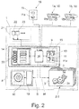
- Fig. 2 shows that the control system 8 preferably has a arranged on the harvester 1 driver assistance system 14, which controls the working members 2-5 of the harvester 1.
- the driver assistance system 14 includes in the illustrated and insofar preferred embodiment, a memory 15 for storing data - that is, a memory in the information technology sense - and a computing device 16 for processing the data stored in the memory 15.
- the driver assistance system 14 is set up to assist a driver 17 of the harvesting machine 1 in operating the harvesting machine 1.
- a remote assistance system 18 is provided, which communicates with the driver assistance system 14.
- the remote assistance system 18 may be a central planning system or the like, the driver assistance system 14 with prognosis inventory information. provided. Alternatively, it may be the remote assistance system 18 to the driver assistance system 14 of another harvester 1, 1a, 1b act.
- the setpoint travel speed S determined by the control system 8 may in principle be a setpoint speed directed to at least one future harvesting process section. This means that a forecast for the driving speed is made by the control system 8. This is particularly advantageous when Abtankzeitnos or the like. be predicted in order to synchronize the harvesting process with transport processes. This will also be explained below. Alternatively or additionally, it may be provided that the target travel speed S determined by the control system 8 is directed to the respective current harvesting process section. In both cases, the proposed solution, in particular the combination of forecasting inventory information 12 and actual stock information 13, ensures optimization of the setpoint driving speed S with regard to the implementation of the respective harvesting process strategy 9.
- the traction drive 10 of the harvester 1 is preferably associated with a vehicle speed control 19, wherein the vehicle speed control 19 sets the driving speed of the harvester 1 based on the respectively determined target vehicle speed S.
- a vehicle speed control 19 sets the driving speed of the harvester 1 based on the respectively determined target vehicle speed S.
- an input / output device 20 is provided, wherein the target vehicle speed S is displayed via the input / output device 20 for user-controlled tracking of the driving speed of the harvester 1.
- the input / output device 20 is a component of the above driver assistance system 14.
- the harvester 1 preferably has a sensor arrangement 21 for determining the actual yield information, which here and preferably comprises a grain tank sensor 22 for determining the fill level of the grain tank 7.
- the sensor assembly 21 may include other sensors such as For example, be associated with a population density sensor 23, as in the Fig. 1 and 2 is shown.
- the target driving speed S may be determined from the harvesting process strategy 9 and from the adapted forecasting inventory model 11a, which at least indirectly maps the actual stock information 13.
- the desired driving speed S is determined from the harvesting process strategy 9 and a here and preferably mathematical link between the actual stock information 13 and the forecast stock information 12.
- the mathematical combination is an averaging between the actual stock information 13 and the forecast stock information 12.
- the prediction inventory model 11 can be structured in different ways. It is preferable that the prediction inventory model 11 comprises reference-mark-predicted prognosis inventory information about the field to be harvested. This means that each prognosis stock information 12 is assigned a measuring mark 24. The measuring mark can be a position on the field to be harvested, a percentage of process progress within the harvesting process, or a point in time.
- Fig. 3a shows extracts from a georeferenced forecast inventory model 11. An exemplary measurement mark has been provided here with the reference numeral 24.
- a prognosis yield map P of the prognosis existing model 11 is shown on the right, wherein each measurement mark 24 in the prediction yield map P is assigned an output information, in particular an output set.
- measuring marks are distributed uniformly over the entire field, whose distances from one another correspond to the location resolution of the respective forecast.
- the measuring marks are distributed along predetermined measuring sections, which can be expected, for example, particularly high or very low yields.
- the forecast inventory model 11 may be composed of different data sources.
- the forecast inventory model 11 is generated, at least in part, from the actual stock information 13 of preceding or parallel harvesting processes.
- the prognosis inventory model 11 at least partially from aerial photographs, in particular satellite images and / or drone recordings is generated.
- the forecast inventory model 11 is at least partially generated from forecast weather information.
- the forecast inventory model 11 or the like at least partially via an input / output device 20. manually entered, field-related data is generated.
- the generation of the forecast inventory model 11 preferably takes place in a remote assistance system 18.
- the forecast inventory model 11 can also be obtained from third parties, in particular from a service provider.
- an above-mentioned adaptation of the prognosis inventory model 11 can be made.
- FIG. 3 Given that the inventory information is in each case yield information.
- yield information is shown along the lane of the harvester 1 around the area of a specific measuring mark 24.
- Fig. 3 shown on the right is the respective yield map, in which the measuring mark 24 is also entered.
- the amount of yield information which is here and preferably the area yield, is indicated in the respective yield map with the density of the points shown within the respective yield map.
- Fig. 3a shows the forecast inventory information 12 while Fig. 3b the actual inventory information up to a measurement mark 24 shows.
- the actual stock information 13 is compared with the respective forecast stock information 12.
- the prediction inventory information 12 is adapted to the actual inventory information 13.
- the thus-adapted forecast inventory model 11a is finally stored.
- the adaptation of the forecast inventory information 12 can be carried out exclusively at the respective measuring mark 24.
- Fig. 3a The representation according to Fig. 3a It can be seen that the prognosis inventory information 12 along the lane x of the harvester 1 have a certain course.
- the actual stock information 13 which is in Fig. 3b
- the proposed control system 8 ensures that the forecast yield information 12 as a whole and in particular for the future process sections to the actual yield information 13 be adapted.
- Fig. 3c illustrated, wherein the adjusted forecast inventory information 12a are indicated by the reference numeral 12a.
- the forecast yield map P is in Fig. 3a indicated by the reference P, while the actual yield map in Fig. 3b is indicated by the reference I.
- the adjusted forecast yield map is in Fig. 3c indicated by the reference numeral A.
- the above-mentioned adaptation of the prognosis inventory model 11 can be made at different locations.
- this adaptation is made in the driver assistance system 14 of the harvester 1.
- the adaptation can also be carried out in a remote assistance system 18 mentioned above.
- the proposed method allows a forward-looking determination of the target driving speed S of the harvester 1 based on a prognosis inventory model 11 with simultaneous inclusion of the actual stock information 13, which enables optimized control of the working organs 2-5 of the harvester 1.
- the proposed determination of the setpoint driving speed S within the framework of the planning of the harvesting process can be helpful if the setpoint driving speed S is also determined for future process sections.
- a preferred example is the implementation of a Abtankstrategie.
- an above Abtankstrategie comprises at least one sub-strategy, which is directed to the reduction of auxiliary times of the harvester 1 and / or on the reduction of transport paths of the respective transport device.
- a harvesting system with at least one self-propelled harvester 1, 1a, 1b, in particular a combine harvester is claimed for carrying out a method mentioned above.
- At least one harvester 1 of the proposed harvesting system is provided with a plurality of working members 2-5 discussed above and a control system 8 equipped to control the working organs 2-5. All statements relating to the proposed method according to the first-mentioned teaching, which are suitable for explaining the harvesting system and in particular the respective harvesting machine 1, may be referred to.
Landscapes
- Life Sciences & Earth Sciences (AREA)
- Environmental Sciences (AREA)
- Management, Administration, Business Operations System, And Electronic Commerce (AREA)
Applications Claiming Priority (1)
| Application Number | Priority Date | Filing Date | Title |
|---|---|---|---|
| DE102015108374.4A DE102015108374A1 (de) | 2015-05-27 | 2015-05-27 | Verfahren zur Ansteuerung einer selbstfahrenden Erntemaschine |
Publications (1)
| Publication Number | Publication Date |
|---|---|
| EP3097759A1 true EP3097759A1 (fr) | 2016-11-30 |
Family
ID=55443182
Family Applications (1)
| Application Number | Title | Priority Date | Filing Date |
|---|---|---|---|
| EP16157834.9A Withdrawn EP3097759A1 (fr) | 2015-05-27 | 2016-02-29 | Procede de commande d'une moissonneuse automotrice |
Country Status (2)
| Country | Link |
|---|---|
| EP (1) | EP3097759A1 (fr) |
| DE (1) | DE102015108374A1 (fr) |
Cited By (41)
| Publication number | Priority date | Publication date | Assignee | Title |
|---|---|---|---|---|
| EP3578032A1 (fr) * | 2018-06-05 | 2019-12-11 | CLAAS Selbstfahrende Erntemaschinen GmbH | Procédé de commande d'une campagne de récolte agricole |
| CN112219538A (zh) * | 2019-07-15 | 2021-01-15 | 克拉斯自行式收获机械有限公司 | 用于进行农业收割过程的方法 |
| EP3818803A1 (fr) * | 2019-11-09 | 2021-05-12 | 365FarmNet Group KGaA mbh & Co KG | Système d'aide à la détermination d'une prévision du bénéfice pour un champ agricole |
| US11079725B2 (en) | 2019-04-10 | 2021-08-03 | Deere & Company | Machine control using real-time model |
| US11178818B2 (en) | 2018-10-26 | 2021-11-23 | Deere & Company | Harvesting machine control system with fill level processing based on yield data |
| US11234366B2 (en) | 2019-04-10 | 2022-02-01 | Deere & Company | Image selection for machine control |
| US11240961B2 (en) | 2018-10-26 | 2022-02-08 | Deere & Company | Controlling a harvesting machine based on a geo-spatial representation indicating where the harvesting machine is likely to reach capacity |
| EP3626038B1 (fr) | 2018-09-24 | 2022-03-09 | CLAAS Tractor S.A.S. | Engin de travail agricole |
| EP3981231A1 (fr) * | 2020-10-08 | 2022-04-13 | Deere & Company | Prédictive génération de carte de caractéristique de machine et système de commande |
| EP3981234A1 (fr) * | 2020-10-08 | 2022-04-13 | Deere & Company | Génération de carte prédictive et système de commande |
| EP3981235A1 (fr) * | 2020-10-08 | 2022-04-13 | Deere & Company | Génération de carte prédictive et système de commande |
| EP3981233A1 (fr) * | 2020-10-08 | 2022-04-13 | Deere & Company | Génération de carte et système de commande |
| US20220110251A1 (en) | 2020-10-09 | 2022-04-14 | Deere & Company | Crop moisture map generation and control system |
| US11467605B2 (en) | 2019-04-10 | 2022-10-11 | Deere & Company | Zonal machine control |
| US11474523B2 (en) | 2020-10-09 | 2022-10-18 | Deere & Company | Machine control using a predictive speed map |
| US11477940B2 (en) | 2020-03-26 | 2022-10-25 | Deere & Company | Mobile work machine control based on zone parameter modification |
| US11592822B2 (en) | 2020-10-09 | 2023-02-28 | Deere & Company | Machine control using a predictive map |
| US11589509B2 (en) | 2018-10-26 | 2023-02-28 | Deere & Company | Predictive machine characteristic map generation and control system |
| US11635765B2 (en) | 2020-10-09 | 2023-04-25 | Deere & Company | Crop state map generation and control system |
| US11641800B2 (en) | 2020-02-06 | 2023-05-09 | Deere & Company | Agricultural harvesting machine with pre-emergence weed detection and mitigation system |
| US11650587B2 (en) | 2020-10-09 | 2023-05-16 | Deere & Company | Predictive power map generation and control system |
| US11653588B2 (en) | 2018-10-26 | 2023-05-23 | Deere & Company | Yield map generation and control system |
| US11672203B2 (en) | 2018-10-26 | 2023-06-13 | Deere & Company | Predictive map generation and control |
| US11675354B2 (en) | 2020-10-09 | 2023-06-13 | Deere & Company | Machine control using a predictive map |
| US11711995B2 (en) | 2020-10-09 | 2023-08-01 | Deere & Company | Machine control using a predictive map |
| US11727680B2 (en) | 2020-10-09 | 2023-08-15 | Deere & Company | Predictive map generation based on seeding characteristics and control |
| US11778945B2 (en) | 2019-04-10 | 2023-10-10 | Deere & Company | Machine control using real-time model |
| US11825768B2 (en) | 2020-10-09 | 2023-11-28 | Deere & Company | Machine control using a predictive map |
| US11844311B2 (en) | 2020-10-09 | 2023-12-19 | Deere & Company | Machine control using a predictive map |
| US11845449B2 (en) | 2020-10-09 | 2023-12-19 | Deere & Company | Map generation and control system |
| US11849671B2 (en) | 2020-10-09 | 2023-12-26 | Deere & Company | Crop state map generation and control system |
| US11849672B2 (en) | 2020-10-09 | 2023-12-26 | Deere & Company | Machine control using a predictive map |
| US11864483B2 (en) | 2020-10-09 | 2024-01-09 | Deere & Company | Predictive map generation and control system |
| US11874669B2 (en) | 2020-10-09 | 2024-01-16 | Deere & Company | Map generation and control system |
| US11889788B2 (en) | 2020-10-09 | 2024-02-06 | Deere & Company | Predictive biomass map generation and control |
| US11889787B2 (en) | 2020-10-09 | 2024-02-06 | Deere & Company | Predictive speed map generation and control system |
| US11895948B2 (en) | 2020-10-09 | 2024-02-13 | Deere & Company | Predictive map generation and control based on soil properties |
| US11927459B2 (en) | 2020-10-09 | 2024-03-12 | Deere & Company | Machine control using a predictive map |
| US11946747B2 (en) | 2020-10-09 | 2024-04-02 | Deere & Company | Crop constituent map generation and control system |
| US11957072B2 (en) | 2020-02-06 | 2024-04-16 | Deere & Company | Pre-emergence weed detection and mitigation system |
| US11983009B2 (en) | 2020-10-09 | 2024-05-14 | Deere & Company | Map generation and control system |
Citations (7)
| Publication number | Priority date | Publication date | Assignee | Title |
|---|---|---|---|---|
| EP0702891A1 (fr) * | 1994-09-07 | 1996-03-27 | CLAAS KGaA | Opération de moissonneuse-batteuse à registre de données opératoires |
| US5995895A (en) * | 1997-07-15 | 1999-11-30 | Case Corporation | Control of vehicular systems in response to anticipated conditions predicted using predetermined geo-referenced maps |
| EP0740896B1 (fr) | 1995-04-15 | 2007-12-12 | CLAAS KGaA | Méthode et dispositif d'optimisation pour l'opération de machines agricoles |
| DE102008032418A1 (de) * | 2008-07-10 | 2010-01-14 | Claas Selbstfahrende Erntemaschinen Gmbh | Landwirtschaftlicher Maschinenverband |
| EP2174537B1 (fr) | 2008-10-08 | 2013-05-22 | CLAAS Selbstfahrende Erntemaschinen GmbH | Procédé de commande d'utilisation de machines agricoles |
| EP2764764A1 (fr) * | 2013-02-07 | 2014-08-13 | Deere & Company | Procédé de réglage de paramètres de travail d'une machine de récolte |
| EP2574235B1 (fr) | 2011-09-28 | 2014-09-10 | Amazonen-Werke H. Dreyer GmbH & Co. KG | Machine de répartition agricole |
Family Cites Families (4)
| Publication number | Priority date | Publication date | Assignee | Title |
|---|---|---|---|---|
| DE10130665A1 (de) * | 2001-06-28 | 2003-01-23 | Deere & Co | Vorrichtung zur Messung der Menge von auf einem Feld stehenden Pflanzen |
| DE102005059003A1 (de) * | 2005-12-08 | 2008-03-27 | Claas Selbstfahrende Erntemaschinen Gmbh | Routenplanungssystem für landwirtschaftliche Arbeitsmaschinen |
| DE102008019018A1 (de) * | 2008-04-15 | 2009-10-22 | Claas Selbstfahrende Erntemaschinen Gmbh | Verfahren und Vorrichtung zur Optimierung von Betriebsparametern einer landwirtschaftlichen Arbeitsmaschine |
| DE102010017676A1 (de) * | 2010-07-01 | 2012-01-05 | Claas Selbstfahrende Erntemaschinen Gmbh | Fahrerassistenzsystem für landwirtschaftliche Arbeitsmaschine |
-
2015
- 2015-05-27 DE DE102015108374.4A patent/DE102015108374A1/de not_active Withdrawn
-
2016
- 2016-02-29 EP EP16157834.9A patent/EP3097759A1/fr not_active Withdrawn
Patent Citations (7)
| Publication number | Priority date | Publication date | Assignee | Title |
|---|---|---|---|---|
| EP0702891A1 (fr) * | 1994-09-07 | 1996-03-27 | CLAAS KGaA | Opération de moissonneuse-batteuse à registre de données opératoires |
| EP0740896B1 (fr) | 1995-04-15 | 2007-12-12 | CLAAS KGaA | Méthode et dispositif d'optimisation pour l'opération de machines agricoles |
| US5995895A (en) * | 1997-07-15 | 1999-11-30 | Case Corporation | Control of vehicular systems in response to anticipated conditions predicted using predetermined geo-referenced maps |
| DE102008032418A1 (de) * | 2008-07-10 | 2010-01-14 | Claas Selbstfahrende Erntemaschinen Gmbh | Landwirtschaftlicher Maschinenverband |
| EP2174537B1 (fr) | 2008-10-08 | 2013-05-22 | CLAAS Selbstfahrende Erntemaschinen GmbH | Procédé de commande d'utilisation de machines agricoles |
| EP2574235B1 (fr) | 2011-09-28 | 2014-09-10 | Amazonen-Werke H. Dreyer GmbH & Co. KG | Machine de répartition agricole |
| EP2764764A1 (fr) * | 2013-02-07 | 2014-08-13 | Deere & Company | Procédé de réglage de paramètres de travail d'une machine de récolte |
Cited By (46)
| Publication number | Priority date | Publication date | Assignee | Title |
|---|---|---|---|---|
| US11240962B2 (en) | 2018-06-05 | 2022-02-08 | Claas Selbstfahrende Erntemaschinen Gmbh | System and method for controlling an agricultural harvesting campaign |
| EP3578032A1 (fr) * | 2018-06-05 | 2019-12-11 | CLAAS Selbstfahrende Erntemaschinen GmbH | Procédé de commande d'une campagne de récolte agricole |
| EP3626038B1 (fr) | 2018-09-24 | 2022-03-09 | CLAAS Tractor S.A.S. | Engin de travail agricole |
| US11589509B2 (en) | 2018-10-26 | 2023-02-28 | Deere & Company | Predictive machine characteristic map generation and control system |
| US11672203B2 (en) | 2018-10-26 | 2023-06-13 | Deere & Company | Predictive map generation and control |
| US11653588B2 (en) | 2018-10-26 | 2023-05-23 | Deere & Company | Yield map generation and control system |
| US11178818B2 (en) | 2018-10-26 | 2021-11-23 | Deere & Company | Harvesting machine control system with fill level processing based on yield data |
| US11240961B2 (en) | 2018-10-26 | 2022-02-08 | Deere & Company | Controlling a harvesting machine based on a geo-spatial representation indicating where the harvesting machine is likely to reach capacity |
| US11778945B2 (en) | 2019-04-10 | 2023-10-10 | Deere & Company | Machine control using real-time model |
| US11829112B2 (en) | 2019-04-10 | 2023-11-28 | Deere & Company | Machine control using real-time model |
| US11234366B2 (en) | 2019-04-10 | 2022-02-01 | Deere & Company | Image selection for machine control |
| US11650553B2 (en) | 2019-04-10 | 2023-05-16 | Deere & Company | Machine control using real-time model |
| US11467605B2 (en) | 2019-04-10 | 2022-10-11 | Deere & Company | Zonal machine control |
| US11079725B2 (en) | 2019-04-10 | 2021-08-03 | Deere & Company | Machine control using real-time model |
| CN112219538A (zh) * | 2019-07-15 | 2021-01-15 | 克拉斯自行式收获机械有限公司 | 用于进行农业收割过程的方法 |
| CN112219538B (zh) * | 2019-07-15 | 2024-05-14 | 克拉斯自行式收获机械有限公司 | 用于进行农业收割过程的方法 |
| EP3818803A1 (fr) * | 2019-11-09 | 2021-05-12 | 365FarmNet Group KGaA mbh & Co KG | Système d'aide à la détermination d'une prévision du bénéfice pour un champ agricole |
| US11957072B2 (en) | 2020-02-06 | 2024-04-16 | Deere & Company | Pre-emergence weed detection and mitigation system |
| US11641800B2 (en) | 2020-02-06 | 2023-05-09 | Deere & Company | Agricultural harvesting machine with pre-emergence weed detection and mitigation system |
| US11477940B2 (en) | 2020-03-26 | 2022-10-25 | Deere & Company | Mobile work machine control based on zone parameter modification |
| EP3981231A1 (fr) * | 2020-10-08 | 2022-04-13 | Deere & Company | Prédictive génération de carte de caractéristique de machine et système de commande |
| EP3981233A1 (fr) * | 2020-10-08 | 2022-04-13 | Deere & Company | Génération de carte et système de commande |
| EP3981235A1 (fr) * | 2020-10-08 | 2022-04-13 | Deere & Company | Génération de carte prédictive et système de commande |
| EP3981234A1 (fr) * | 2020-10-08 | 2022-04-13 | Deere & Company | Génération de carte prédictive et système de commande |
| US11650587B2 (en) | 2020-10-09 | 2023-05-16 | Deere & Company | Predictive power map generation and control system |
| US11675354B2 (en) | 2020-10-09 | 2023-06-13 | Deere & Company | Machine control using a predictive map |
| US11711995B2 (en) | 2020-10-09 | 2023-08-01 | Deere & Company | Machine control using a predictive map |
| US11727680B2 (en) | 2020-10-09 | 2023-08-15 | Deere & Company | Predictive map generation based on seeding characteristics and control |
| US11635765B2 (en) | 2020-10-09 | 2023-04-25 | Deere & Company | Crop state map generation and control system |
| US11592822B2 (en) | 2020-10-09 | 2023-02-28 | Deere & Company | Machine control using a predictive map |
| US11825768B2 (en) | 2020-10-09 | 2023-11-28 | Deere & Company | Machine control using a predictive map |
| US11844311B2 (en) | 2020-10-09 | 2023-12-19 | Deere & Company | Machine control using a predictive map |
| US11845449B2 (en) | 2020-10-09 | 2023-12-19 | Deere & Company | Map generation and control system |
| US11849671B2 (en) | 2020-10-09 | 2023-12-26 | Deere & Company | Crop state map generation and control system |
| US11849672B2 (en) | 2020-10-09 | 2023-12-26 | Deere & Company | Machine control using a predictive map |
| US11864483B2 (en) | 2020-10-09 | 2024-01-09 | Deere & Company | Predictive map generation and control system |
| US11874669B2 (en) | 2020-10-09 | 2024-01-16 | Deere & Company | Map generation and control system |
| US11871697B2 (en) | 2020-10-09 | 2024-01-16 | Deere & Company | Crop moisture map generation and control system |
| US11889788B2 (en) | 2020-10-09 | 2024-02-06 | Deere & Company | Predictive biomass map generation and control |
| US11889787B2 (en) | 2020-10-09 | 2024-02-06 | Deere & Company | Predictive speed map generation and control system |
| US11895948B2 (en) | 2020-10-09 | 2024-02-13 | Deere & Company | Predictive map generation and control based on soil properties |
| US11927459B2 (en) | 2020-10-09 | 2024-03-12 | Deere & Company | Machine control using a predictive map |
| US11946747B2 (en) | 2020-10-09 | 2024-04-02 | Deere & Company | Crop constituent map generation and control system |
| US11474523B2 (en) | 2020-10-09 | 2022-10-18 | Deere & Company | Machine control using a predictive speed map |
| US20220110251A1 (en) | 2020-10-09 | 2022-04-14 | Deere & Company | Crop moisture map generation and control system |
| US11983009B2 (en) | 2020-10-09 | 2024-05-14 | Deere & Company | Map generation and control system |
Also Published As
| Publication number | Publication date |
|---|---|
| DE102015108374A1 (de) | 2016-12-01 |
Similar Documents
| Publication | Publication Date | Title |
|---|---|---|
| EP3097759A1 (fr) | Procede de commande d'une moissonneuse automotrice | |
| EP2764764B1 (fr) | Procédé de réglage de paramètres de travail d'une machine de récolte | |
| EP3085221B1 (fr) | Système de récolte comprenant une moissonneuse automobile | |
| EP3666050B1 (fr) | Système de travail agricole | |
| EP3459338B1 (fr) | Machine de travail | |
| EP3075223B1 (fr) | Moissonneuse-batteuse | |
| EP3132711B1 (fr) | Moissonneuse agricole | |
| EP3533314B1 (fr) | Moissonneuse automotrice et son procédé de fonctionnement | |
| EP3076248B1 (fr) | Moissonneuse-batteuse | |
| EP3075224B1 (fr) | Moissonneuse-batteuse | |
| EP3180974A1 (fr) | Procédé de fonctionnement d'une moissonneuse-batteuse | |
| EP1741329B1 (fr) | Méthode et appareil pour l'optimisation des paramètres de fonctionnement d'une machine de travail agricole | |
| EP3566564A1 (fr) | Moissonneuse-batteuse et procédé de fonctionnement d'une moissonneuse-batteuse | |
| EP1731017B1 (fr) | Méthode de commande d'une moissoneuse | |
| DE102018111076A1 (de) | Mähdrescher | |
| EP3178307A1 (fr) | Engin agricole | |
| DE102008032418A1 (de) | Landwirtschaftlicher Maschinenverband | |
| DE102008056557A1 (de) | Erstellung von Bilddatenbanken für Bildauswertung | |
| DE102017201421A1 (de) | Steueranordnung für eine Schleifeinrichtung und/oder Einrichtung zur Einstellung der Position einer Gegenschneide eines Feldhäckslers | |
| EP2110012B1 (fr) | Procédé et dispositif d'optimisation de paramètres de fonctionnement d'une machine de travail agricole | |
| DE102021121296A1 (de) | Verfahren für den Betrieb einer selbstfahrenden landwirtschaftlichen Erntemaschine sowie selbstfahrende landwirtschaftliche Erntemaschine | |
| EP3242257A1 (fr) | Procédé et agencement d'optimisation de paramètres de travail d'une machine de récolte | |
| DE102006044159A1 (de) | Anzeigeeinheit einer landwirtschaftlichen Arbeitsmaschine | |
| DE102022107016A1 (de) | Landwirtschaftliche Erntemaschine sowie Verfahren zur Steuerung einer landwirtschaftlichen Erntemaschine | |
| DE102021125099A1 (de) | Erntemaschine mit Bandschneidwerk |
Legal Events
| Date | Code | Title | Description |
|---|---|---|---|
| PUAI | Public reference made under article 153(3) epc to a published international application that has entered the european phase |
Free format text: ORIGINAL CODE: 0009012 |
|
| AK | Designated contracting states |
Kind code of ref document: A1 Designated state(s): AL AT BE BG CH CY CZ DE DK EE ES FI FR GB GR HR HU IE IS IT LI LT LU LV MC MK MT NL NO PL PT RO RS SE SI SK SM TR |
|
| AX | Request for extension of the european patent |
Extension state: BA ME |
|
| RIN1 | Information on inventor provided before grant (corrected) |
Inventor name: RUSCH, CHRISTIAN Inventor name: KERSTING, THOMAS Inventor name: SCHILLMOELLER, THORSTEN Inventor name: SMOLNIK, IVAN Inventor name: STECKEL, THILO Inventor name: GROTHAUS, HANS-PETER, DR. Inventor name: WILSKE, ANJA Inventor name: KREIS, FLORIAN Inventor name: REINECKE, DR., MAX Inventor name: SCHAEPERKOETTER, CHRISTIAN |
|
| 17P | Request for examination filed |
Effective date: 20170530 |
|
| RBV | Designated contracting states (corrected) |
Designated state(s): AL AT BE BG CH CY CZ DE DK EE ES FI FR GB GR HR HU IE IS IT LI LT LU LV MC MK MT NL NO PL PT RO RS SE SI SK SM TR |
|
| STAA | Information on the status of an ep patent application or granted ep patent |
Free format text: STATUS: THE APPLICATION IS DEEMED TO BE WITHDRAWN |
|
| 18D | Application deemed to be withdrawn |
Effective date: 20170531 |