EP3097379B1 - Heat exchanger - Google Patents
Heat exchanger Download PDFInfo
- Publication number
- EP3097379B1 EP3097379B1 EP15701339.2A EP15701339A EP3097379B1 EP 3097379 B1 EP3097379 B1 EP 3097379B1 EP 15701339 A EP15701339 A EP 15701339A EP 3097379 B1 EP3097379 B1 EP 3097379B1
- Authority
- EP
- European Patent Office
- Prior art keywords
- heat exchanger
- tubes
- coolant
- plate
- cover
- Prior art date
- Legal status (The legal status is an assumption and is not a legal conclusion. Google has not performed a legal analysis and makes no representation as to the accuracy of the status listed.)
- Active
Links
Images


Classifications
-
- F—MECHANICAL ENGINEERING; LIGHTING; HEATING; WEAPONS; BLASTING
- F28—HEAT EXCHANGE IN GENERAL
- F28F—DETAILS OF HEAT-EXCHANGE AND HEAT-TRANSFER APPARATUS, OF GENERAL APPLICATION
- F28F9/00—Casings; Header boxes; Auxiliary supports for elements; Auxiliary members within casings
- F28F9/02—Header boxes; End plates
- F28F9/0219—Arrangements for sealing end plates into casing or header box; Header box sub-elements
- F28F9/0224—Header boxes formed by sealing end plates into covers
-
- F—MECHANICAL ENGINEERING; LIGHTING; HEATING; WEAPONS; BLASTING
- F02—COMBUSTION ENGINES; HOT-GAS OR COMBUSTION-PRODUCT ENGINE PLANTS
- F02B—INTERNAL-COMBUSTION PISTON ENGINES; COMBUSTION ENGINES IN GENERAL
- F02B29/00—Engines characterised by provision for charging or scavenging not provided for in groups F02B25/00, F02B27/00 or F02B33/00 - F02B39/00; Details thereof
- F02B29/04—Cooling of air intake supply
- F02B29/045—Constructional details of the heat exchangers, e.g. pipes, plates, ribs, insulation, materials, or manufacturing and assembly
- F02B29/0475—Constructional details of the heat exchangers, e.g. pipes, plates, ribs, insulation, materials, or manufacturing and assembly the intake air cooler being combined with another device, e.g. heater, valve, compressor, filter or EGR cooler, or being assembled on a special engine location
-
- F—MECHANICAL ENGINEERING; LIGHTING; HEATING; WEAPONS; BLASTING
- F28—HEAT EXCHANGE IN GENERAL
- F28D—HEAT-EXCHANGE APPARATUS, NOT PROVIDED FOR IN ANOTHER SUBCLASS, IN WHICH THE HEAT-EXCHANGE MEDIA DO NOT COME INTO DIRECT CONTACT
- F28D1/00—Heat-exchange apparatus having stationary conduit assemblies for one heat-exchange medium only, the media being in contact with different sides of the conduit wall, in which the other heat-exchange medium is a large body of fluid, e.g. domestic or motor car radiators
- F28D1/02—Heat-exchange apparatus having stationary conduit assemblies for one heat-exchange medium only, the media being in contact with different sides of the conduit wall, in which the other heat-exchange medium is a large body of fluid, e.g. domestic or motor car radiators with heat-exchange conduits immersed in the body of fluid
- F28D1/04—Heat-exchange apparatus having stationary conduit assemblies for one heat-exchange medium only, the media being in contact with different sides of the conduit wall, in which the other heat-exchange medium is a large body of fluid, e.g. domestic or motor car radiators with heat-exchange conduits immersed in the body of fluid with tubular conduits
- F28D1/0408—Multi-circuit heat exchangers, e.g. integrating different heat exchange sections in the same unit or heat exchangers for more than two fluids
- F28D1/0426—Multi-circuit heat exchangers, e.g. integrating different heat exchange sections in the same unit or heat exchangers for more than two fluids with units having particular arrangement relative to the large body of fluid, e.g. with interleaved units or with adjacent heat exchange units in common air flow or with units extending at an angle to each other or with units arranged around a central element
- F28D1/0435—Combination of units extending one behind the other
-
- F—MECHANICAL ENGINEERING; LIGHTING; HEATING; WEAPONS; BLASTING
- F28—HEAT EXCHANGE IN GENERAL
- F28D—HEAT-EXCHANGE APPARATUS, NOT PROVIDED FOR IN ANOTHER SUBCLASS, IN WHICH THE HEAT-EXCHANGE MEDIA DO NOT COME INTO DIRECT CONTACT
- F28D1/00—Heat-exchange apparatus having stationary conduit assemblies for one heat-exchange medium only, the media being in contact with different sides of the conduit wall, in which the other heat-exchange medium is a large body of fluid, e.g. domestic or motor car radiators
- F28D1/02—Heat-exchange apparatus having stationary conduit assemblies for one heat-exchange medium only, the media being in contact with different sides of the conduit wall, in which the other heat-exchange medium is a large body of fluid, e.g. domestic or motor car radiators with heat-exchange conduits immersed in the body of fluid
- F28D1/04—Heat-exchange apparatus having stationary conduit assemblies for one heat-exchange medium only, the media being in contact with different sides of the conduit wall, in which the other heat-exchange medium is a large body of fluid, e.g. domestic or motor car radiators with heat-exchange conduits immersed in the body of fluid with tubular conduits
- F28D1/053—Heat-exchange apparatus having stationary conduit assemblies for one heat-exchange medium only, the media being in contact with different sides of the conduit wall, in which the other heat-exchange medium is a large body of fluid, e.g. domestic or motor car radiators with heat-exchange conduits immersed in the body of fluid with tubular conduits the conduits being straight
- F28D1/0535—Heat-exchange apparatus having stationary conduit assemblies for one heat-exchange medium only, the media being in contact with different sides of the conduit wall, in which the other heat-exchange medium is a large body of fluid, e.g. domestic or motor car radiators with heat-exchange conduits immersed in the body of fluid with tubular conduits the conduits being straight the conduits having a non-circular cross-section
- F28D1/05366—Assemblies of conduits connected to common headers, e.g. core type radiators
- F28D1/05375—Assemblies of conduits connected to common headers, e.g. core type radiators with particular pattern of flow, e.g. change of flow direction
-
- F—MECHANICAL ENGINEERING; LIGHTING; HEATING; WEAPONS; BLASTING
- F28—HEAT EXCHANGE IN GENERAL
- F28D—HEAT-EXCHANGE APPARATUS, NOT PROVIDED FOR IN ANOTHER SUBCLASS, IN WHICH THE HEAT-EXCHANGE MEDIA DO NOT COME INTO DIRECT CONTACT
- F28D7/00—Heat-exchange apparatus having stationary tubular conduit assemblies for both heat-exchange media, the media being in contact with different sides of a conduit wall
- F28D7/0066—Multi-circuit heat-exchangers, e.g. integrating different heat exchange sections in the same unit or heat-exchangers for more than two fluids
- F28D7/0083—Multi-circuit heat-exchangers, e.g. integrating different heat exchange sections in the same unit or heat-exchangers for more than two fluids with units having particular arrangement relative to a supplementary heat exchange medium, e.g. with interleaved units or with adjacent units arranged in common flow of supplementary heat exchange medium
- F28D7/0091—Multi-circuit heat-exchangers, e.g. integrating different heat exchange sections in the same unit or heat-exchangers for more than two fluids with units having particular arrangement relative to a supplementary heat exchange medium, e.g. with interleaved units or with adjacent units arranged in common flow of supplementary heat exchange medium the supplementary medium flowing in series through the units
-
- F—MECHANICAL ENGINEERING; LIGHTING; HEATING; WEAPONS; BLASTING
- F28—HEAT EXCHANGE IN GENERAL
- F28D—HEAT-EXCHANGE APPARATUS, NOT PROVIDED FOR IN ANOTHER SUBCLASS, IN WHICH THE HEAT-EXCHANGE MEDIA DO NOT COME INTO DIRECT CONTACT
- F28D7/00—Heat-exchange apparatus having stationary tubular conduit assemblies for both heat-exchange media, the media being in contact with different sides of a conduit wall
- F28D7/16—Heat-exchange apparatus having stationary tubular conduit assemblies for both heat-exchange media, the media being in contact with different sides of a conduit wall the conduits being arranged in parallel spaced relation
- F28D7/1615—Heat-exchange apparatus having stationary tubular conduit assemblies for both heat-exchange media, the media being in contact with different sides of a conduit wall the conduits being arranged in parallel spaced relation the conduits being inside a casing and extending at an angle to the longitudinal axis of the casing; the conduits crossing the conduit for the other heat exchange medium
- F28D7/1623—Heat-exchange apparatus having stationary tubular conduit assemblies for both heat-exchange media, the media being in contact with different sides of a conduit wall the conduits being arranged in parallel spaced relation the conduits being inside a casing and extending at an angle to the longitudinal axis of the casing; the conduits crossing the conduit for the other heat exchange medium with particular pattern of flow of the heat exchange media, e.g. change of flow direction
-
- F—MECHANICAL ENGINEERING; LIGHTING; HEATING; WEAPONS; BLASTING
- F28—HEAT EXCHANGE IN GENERAL
- F28D—HEAT-EXCHANGE APPARATUS, NOT PROVIDED FOR IN ANOTHER SUBCLASS, IN WHICH THE HEAT-EXCHANGE MEDIA DO NOT COME INTO DIRECT CONTACT
- F28D7/00—Heat-exchange apparatus having stationary tubular conduit assemblies for both heat-exchange media, the media being in contact with different sides of a conduit wall
- F28D7/16—Heat-exchange apparatus having stationary tubular conduit assemblies for both heat-exchange media, the media being in contact with different sides of a conduit wall the conduits being arranged in parallel spaced relation
- F28D7/1684—Heat-exchange apparatus having stationary tubular conduit assemblies for both heat-exchange media, the media being in contact with different sides of a conduit wall the conduits being arranged in parallel spaced relation the conduits having a non-circular cross-section
- F28D7/1692—Heat-exchange apparatus having stationary tubular conduit assemblies for both heat-exchange media, the media being in contact with different sides of a conduit wall the conduits being arranged in parallel spaced relation the conduits having a non-circular cross-section with particular pattern of flow of the heat exchange media, e.g. change of flow direction
-
- F—MECHANICAL ENGINEERING; LIGHTING; HEATING; WEAPONS; BLASTING
- F28—HEAT EXCHANGE IN GENERAL
- F28F—DETAILS OF HEAT-EXCHANGE AND HEAT-TRANSFER APPARATUS, OF GENERAL APPLICATION
- F28F9/00—Casings; Header boxes; Auxiliary supports for elements; Auxiliary members within casings
- F28F9/02—Header boxes; End plates
- F28F9/0202—Header boxes having their inner space divided by partitions
-
- F—MECHANICAL ENGINEERING; LIGHTING; HEATING; WEAPONS; BLASTING
- F28—HEAT EXCHANGE IN GENERAL
- F28F—DETAILS OF HEAT-EXCHANGE AND HEAT-TRANSFER APPARATUS, OF GENERAL APPLICATION
- F28F9/00—Casings; Header boxes; Auxiliary supports for elements; Auxiliary members within casings
- F28F9/02—Header boxes; End plates
- F28F9/0246—Arrangements for connecting header boxes with flow lines
- F28F9/0251—Massive connectors, e.g. blocks; Plate-like connectors
- F28F9/0253—Massive connectors, e.g. blocks; Plate-like connectors with multiple channels, e.g. with combined inflow and outflow channels
-
- F—MECHANICAL ENGINEERING; LIGHTING; HEATING; WEAPONS; BLASTING
- F28—HEAT EXCHANGE IN GENERAL
- F28D—HEAT-EXCHANGE APPARATUS, NOT PROVIDED FOR IN ANOTHER SUBCLASS, IN WHICH THE HEAT-EXCHANGE MEDIA DO NOT COME INTO DIRECT CONTACT
- F28D21/00—Heat-exchange apparatus not covered by any of the groups F28D1/00 - F28D20/00
- F28D2021/0019—Other heat exchangers for particular applications; Heat exchange systems not otherwise provided for
- F28D2021/008—Other heat exchangers for particular applications; Heat exchange systems not otherwise provided for for vehicles
- F28D2021/0082—Charged air coolers
-
- F—MECHANICAL ENGINEERING; LIGHTING; HEATING; WEAPONS; BLASTING
- F28—HEAT EXCHANGE IN GENERAL
- F28F—DETAILS OF HEAT-EXCHANGE AND HEAT-TRANSFER APPARATUS, OF GENERAL APPLICATION
- F28F2275/00—Fastening; Joining
- F28F2275/04—Fastening; Joining by brazing
-
- F—MECHANICAL ENGINEERING; LIGHTING; HEATING; WEAPONS; BLASTING
- F28—HEAT EXCHANGE IN GENERAL
- F28F—DETAILS OF HEAT-EXCHANGE AND HEAT-TRANSFER APPARATUS, OF GENERAL APPLICATION
- F28F2275/00—Fastening; Joining
- F28F2275/06—Fastening; Joining by welding
-
- Y—GENERAL TAGGING OF NEW TECHNOLOGICAL DEVELOPMENTS; GENERAL TAGGING OF CROSS-SECTIONAL TECHNOLOGIES SPANNING OVER SEVERAL SECTIONS OF THE IPC; TECHNICAL SUBJECTS COVERED BY FORMER USPC CROSS-REFERENCE ART COLLECTIONS [XRACs] AND DIGESTS
- Y02—TECHNOLOGIES OR APPLICATIONS FOR MITIGATION OR ADAPTATION AGAINST CLIMATE CHANGE
- Y02T—CLIMATE CHANGE MITIGATION TECHNOLOGIES RELATED TO TRANSPORTATION
- Y02T10/00—Road transport of goods or passengers
- Y02T10/10—Internal combustion engine [ICE] based vehicles
- Y02T10/12—Improving ICE efficiencies
Definitions
- the invention relates to a heat exchanger, in particular in a motor vehicle, in particular a heat exchanger for cooling charge air for an internal combustion engine in the motor vehicle.
- a heat exchanger in an intake tract of a supercharged internal combustion engine can be used as a charge air cooler (LLK).
- the charge air cooler is typically disposed between a compressor, particularly a compressor wheel of a turbocharger or compressor in an intake manifold of the internal combustion engine and an intake valve, and serves to dissipate a portion of the heat that may result from the compression of the air in a turbocharger. As a result, the performance and the efficiency of the internal combustion engine can be increased.
- a stepped, sequential intercooler also referred to as an indirect intercooler (iLLK) will typically be located close to the engine between the compressor and a throttle and operate as an air / coolant radiator. This is typically done by the charge air Heat is removed and the charge air can therefore be cooled.
- the indirect charge air cooler iLLK
- the indirect charge air cooler has two independent, separate coolant circuits, the air being recooled in a low temperature cooler of a low temperature circuit.
- Known indirect intercoolers typically have a finned tube system.
- the apparatus includes a plurality of first coolant tubes for guiding a first coolant and a plurality of second coolant tubes for guiding a second coolant, the first coolant tubes and the second coolant tubes extending along a longitudinal direction of the device and the plurality of first coolant tubes with respect to the plurality of second coolant tubes are arranged adjacent in a transverse extension direction of the device.
- the end-side header boxes are each formed with a common bottom and common header boxes, in which partitions are provided for subdivision.
- first coolant circuit having a plurality of first tubes
- second coolant circuit having a plurality of second tubes
- the floor has a first floor area with openings for receiving the first pipes and a second floor area with openings for receiving the second pipes
- first collection box is fluid-tightly connected to the first floor area
- the second collection box is fluid-tightly connected to the second floor area
- the cover between the first and the second collection box has an opening for receiving the bead.
- the bead is preferably a groove-shaped depression, which is embossed in the ground.
- the soil may have a bottom embossing.
- the first tubes and the second tubes are preferably coolant tubes through which a coolant can flow.
- the tubes are designed as flat tubes.
- the first collection box is preferably substantially parallel to the first floor area, and the second collection box is preferably arranged substantially parallel to the second floor area of the floor of the heat exchanger.
- a header side wall of the first and / or second header tank is / are arranged substantially perpendicular to the floor.
- the opening of the cover is punched out.
- the punched hole can form a recess.
- the bead in the bottom and the preferably oppositely disposed bead may engage with each other, particularly when the first and second header boxes are connected to the first and second tubes. This allows an optimal centering between the bottom with the bead and the recess on the cover.
- the recess may be arranged on or adjacent to the respective collection box wall.
- the floor preferably has a circumferential area.
- a connecting seam is produced, which is preferably circumferential.
- the bottom and the first and the second collection box are soldered circumferentially and form a circumferential soldering seam.
- the cover is non-positively and positively connected to the ground.
- the cover is soldered to the ground.
- the connection technique can also be another known connection technique.
- the cover and the bottom can be welded, in particular, then a weld can be formed in the region of the bead and the recess.
- a fluid-tight connection can be realized directly between the floor and the respective collecting tank, so that the first coolant circuit and the second coolant circuit are reliably separated, in particular at the interface to the respective floor area.
- a possible leak in the first and / or the second collection box can always go first to the outside. So no internal leakage can occur. In particular, it can not come to a connection between the first and the second coolant circuit and a coupling of the coolant circuits can be excluded.
- the cover with the bottom preferably forms a first inlet channel for the first header box, a first outlet channel for the first header box and a second channel for the second header box.
- the bottom may have openings for the first inlet channel, the first outlet channel and the second channel.
- the second channel may also have an inlet channel and a discharge channel.
- a first inlet nozzle, a first outlet nozzle, a second inlet nozzle and a second outlet nozzle be arranged.
- the nozzles can be connected to the associated channels or connected.
- the bottom preferably has openings for the first inlet channel, the first outlet channel, the second inlet channel and / or the second outlet channel.
- the soil is preferably connected in a separate process step with the respective collection box, in particular in a brazing furnace.
- the soldering between the floor and the respective collection box is done directly and not only due to external soldering of the header tank or parts of the header tank, as is often the case in the prior art. It is advantageous in this case that a separation of the first and the second coolant circuit can be carried out without a partition with the necessary complex Montagenach former between the first and the second coolant circuit at the interface between the first and the second collection box is arranged. It can thus be saved a partition wall tool.
- a first and a second heat exchanger are provided, wherein the first heat transfer element in the first coolant circuit is a high-temperature cooler.
- the first heat transfer element in the first coolant circuit is a high-temperature cooler.
- a flange on which an inlet channel is arranged, may be provided on the first collecting box, through which the coolant can pass into the first tubes.
- a further first collection box is then preferably arranged, on which an outlet channel for the coolant is arranged.
- the second heat transfer element in the second coolant circuit is a low-temperature cooler.
- the second heat exchanger element with the second coolant circuit can in this case be constructed as a U-flow heat exchanger element.
- Inlet duct disposed on the flange and an outlet duct on the flange to the second collection box.
- the heat exchanger is in particular an indirect intercooler.
- a better heat transfer between the charge air and the coolant or between the coolant and the ambient air when operating in the low-temperature circuit can be achieved. This can allow an increase in performance of the intercooler.
- the low-temperature radiator (iLLK) and the high-temperature radiator (iLLK) can be connected to each other via the floor with the soldered first and second collection box.
- the low-temperature radiator and the high-temperature radiator belong here to different coolant circuits, in particular the first coolant circuit and the second coolant circuit. Due to the soldered bead / punched connection, the first and the second coolant circuit are separated safely flow-mechanically and no fluidic coupling can take place. The separation is one hundred percent tight (100% tight).
- the heat exchanger on a partition in the second coolant circuit which is adapted to realize a separation of a coolant flow and a coolant return.
- the partition wall is preferably connected to the ground and a wall of the header tank opposite the bottom and separates the flow and the return in the second header. Thus, a deflection of the coolant can take place.
- first heat exchanger element and a second heat exchanger element are provided, which are arranged adjacent to and parallel to each other.
- first heat exchanger element and the second heat exchanger element each have tubes, wherein the tubes of the first and the second heat exchanger element are arranged parallel to each other.
- the object is also achieved with a motor vehicle having a heat exchanger according to the invention.
- the heat exchanger is preferably a sequential intercooler integrated in the intake manifold with two separate coolant circuits.
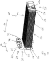
- the FIG. 1 shows an exploded view of a heat exchanger 10.
- the heat exchanger 10 is in the illustrated embodiment, a charge air cooler 10 and can be used to cool the charge air for an internal combustion engine of a motor vehicle.
- the heat exchanger 10 has in the illustrated embodiment, a first heat transfer element 12, which is constructed as an I-flow heat exchanger, and a second heat transfer element 14, which is constructed as a U-flow heat exchanger.
- the first heat transfer element 12 is preferably a high-temperature cooler and the second heat transfer element 14 is preferably a low-temperature cooler.
- the first heat transfer element 12 is part of a first coolant circuit (not shown) and the second heat transfer element is part of a second coolant circuit (not shown).
- the heat exchanger 10 may in this case be in particular a sequential, indirect intercooler (iLLK) 10.
- iLLK sequential, indirect intercooler
- the indirect intercooler may have two independent, separate coolant circuits.
- the hot charge air in one stage, is pre-cooled with warm coolant from, for example, the engine's main cooling circuit and cooled in a downstream second stage with cold coolant of a low temperature radiator.
- a known construction of a sequential indirect intercooler is the fin-tube system.
- the first coolant circuit with the heat transfer element 12 and the second coolant circuit with the second heat transfer element 14 each have a plurality of tubes 15, 19, wherein through the tubes 15 of the first coolant circuit, a first coolant and through the tubes 19 of the second coolant circuit, a second fluid can flow.
- the tubes 15 and 19 are preferably flat tubes.
- the coolant circuits are preferably independent of each other and can be operated in particular with different parameters.
- the coolant of the first coolant circuit and the coolant of the second coolant circuit may be under different pressure.
- the coolant may be a liquid or a gaseous fluid.
- the first tubes 15 of the first heat exchanger element 12 are arranged in the longitudinal direction 16 of the heat exchanger 10 in a housing, not shown.
- the tubes 15, 19 are respectively arranged on a first tube end 20 and / or on a second tube end 22 on or in a bottom 23 and are fixed by this in position.
- the first and second header boxes 24 and 28 are preferably disposed at both ends 20, 22 of the tubes 15, 19, respectively.
- a connection channel or outlet channel 26 is arranged.
- the first and second collection boxes 24 and 28 are substantially trough-shaped.
- the first header box 24 and the second header box 28 together form the cover 25.
- the second tubes 19 of the second heat exchanger element 14 are seen in the longitudinal direction 16 is arranged substantially parallel to each other and parallel to the first tubes 15 of the first heat transfer element 12.
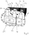
- FIG. 2 the heat exchanger 10 is shown in a perspective view in assembled state. Like parts are designated by the same reference numerals.
- the tubes 15, 19, in particular flat tubes 15, 19, are optionally arranged in a housing 18 and form the tube-fin block of a rib-tube heat exchanger.
- the cover 25 has the first collection box 24 and the second collection box 28 and closes the housing 18 at least on one of the sides 20, 22 from.
- a cover 25 is arranged on each side.
- a flange 30 is arranged at the end 20 of the tubes 15 and 19, .
- the flange 30 has at least one peripheral region projecting beyond the transverse extension direction 17 of the tubes 15 and 19.
- the flange 30 preferably has an area projecting beyond the cover 25.
- a first inlet channel 32 and a first outlet channel 34 are arranged on the flange 30. Furthermore, a second connection channel 36, which is preferably an inlet channel 36, opposite to the first connection channel 26, which is preferably an outlet channel 26, is arranged on the flange 30.
- the inlet channel 32 and the outlet channel 34 are part of the U-flow formed heat transfer element 14.
- the channel 26 and the channel 36 are part of the formed as I-flow heat transfer element 12.
- the bottom 23 is between the cover 25, the first collection box 24th and the second header box 28, and the tubes 15 and 19 are arranged.
- the embodiment of the heat exchanger 10 as a three-part heat exchanger 10 is merely an example.
- the heat exchanger 10 may also be a four-part heat exchanger having two U-flow heat transfer elements.
- FIG. 3 shows the heat exchanger 10 in a perspective view looking towards the cover 25 and that at the end 20 of the tubes 15 and 19.
- the bottom 23 includes in the region of the respective header box 24, 28, the first bottom portion 44 and the second bottom portion 46, wherein the first bottom portion 44 associated with the first collection box 24 and the second bottom portion 46 is associated with the second collection box 28.
- a connecting seam 48 is arranged between the first bottom portion 44 and the second bottom portion 46.
- the connecting seam 48 is formed by a bead 52 engages in a recess 50 and soldered.
- the first collection box 24 is in this case connected fluid-tightly directly to the bottom 23, preferably not detachably connected.
- the connection between the bottom 23 may preferably be realized by means of soldering.
- any other connection technique known per se such as gluing or welding, which is suitable for producing a fluid-tight connection, in particular from a bead 52 arranged in the recess 50. In this way, a non-positive and positive connection is established between the floor 23 and the cover 25 made.
- a plurality of first tubes 15 of the first heat exchanger element 12 are arranged on or in the first bottom section 44 and fixed on or in this.
- a plurality of second tubes 19 are disposed in the second bottom portion 46 and fixed to or in this.
- the connecting portion 48 or the connecting seam 48 has the in the collecting box 24 and / or the collecting box 28, in particular in the cover 25, introduced punched 50 and in the bottom 23rd arranged bead 52 on.
- the bead 52 may engage with the recess 50 or cutout 50, particularly in mechanical engagement.
- the punching / beading pairing can greatly simplify the assembly of the collecting box 24 at the bottom 23 by allowing a nearly automatic centering.
- the punched-out / beading connection forms the connecting seam 48, preferably the soldering seam 48.
- a partition wall 49 is arranged in the collecting box 28, which can realize a deflection of the coolant flow between coolant supply and coolant return.
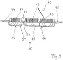
- the partition wall 49 is in the sectional view of the heat exchanger 10 of FIG. 4 shown.
- the first collection box 24 and the second collection box 28 may be formed as a one-piece component, as the cover 25.
- the first collection box 24 and the second collection box 28 may also initially be made in two parts and connected so that the cover 25 is formed.
- the cutout 50 is chosen such that the bead 52 can protrude into this.
- FIG. 5 is an illustration of a mounted and soldered heat exchanger 10 in plan view of the collection box 24 and 28, so seen in the longitudinal direction 16 frontally on the first collection box 24 and the second collection box 28.
- Recognizable is the seam 48, which is formed as a solder seam 48.
- the connecting seam 48 is preferably a peripheral connecting seam 48 or part of a peripheral connecting seam.
Description
Die Erfindung betrifft einen Wärmeübertrager, insbesondere in einem Kraftfahrzeug, insbesondere einen Wärmeübertrager zum Kühlen von Ladeluft für einen Verbrennungsmotor in dem Kraftfahrzeug. Ein Wärmeübertrager nach dem Oberbegriff des Anspruchs 1 ist z.B. aus
In einem Kraftfahrzeug kann ein Wärmeübertrager in einem Ansaugtrakt eines aufgeladenen Verbrennungsmotors als Ladeluftkühler (LLK) eingesetzt werden. Der Ladeluftkühler ist typischerweise zwischen einem Verdichter, insbesondere einem Verdichterrad eines Turboladers oder Kompressors in einem Ansaugtrakt des Verbrennungsmotors und einem Einlassventil angeordnet und dient dazu, einen Teil der Wärme abzuführen, die durch die Verdichtung der Luft in einem Turbolader entstehen kann. Dadurch kann die Leistung und der Wirkungsgrad des Verbrennungsmotors erhöht werden.In a motor vehicle, a heat exchanger in an intake tract of a supercharged internal combustion engine can be used as a charge air cooler (LLK). The charge air cooler is typically disposed between a compressor, particularly a compressor wheel of a turbocharger or compressor in an intake manifold of the internal combustion engine and an intake valve, and serves to dissipate a portion of the heat that may result from the compression of the air in a turbocharger. As a result, the performance and the efficiency of the internal combustion engine can be increased.
Ein gestufter, sequentieller Ladeluftkühler, der auch als indirekter Ladeluftkühler (iLLK) bezeichnet wird, wird typischerweise motornah zwischen dem Verdichter und einer Drosselklappe angeordnet sein und als Luft-/Kühlmittelkühler arbeiten. Dies geschieht typischerweise, indem der Ladeluft Wärme entzogen wird und die Ladeluft folglich gekühlt werden kann. In einer kompakten Ausführungsform weist der indirekte Ladeluftkühler (iLLK) zwei voneinander unabhängige, getrennte Kühlmittelkreisläufe auf, wobei die Luft in einem Niedertemperaturkühler eines Niedertemperaturkreislaufs rückgekühlt wird. Bekannte indirekte Ladeluftkühler weisen typischerweise ein RippenRohr-System auf.A stepped, sequential intercooler, also referred to as an indirect intercooler (iLLK), will typically be located close to the engine between the compressor and a throttle and operate as an air / coolant radiator. This is typically done by the charge air Heat is removed and the charge air can therefore be cooled. In a compact embodiment, the indirect charge air cooler (iLLK) has two independent, separate coolant circuits, the air being recooled in a low temperature cooler of a low temperature circuit. Known indirect intercoolers typically have a finned tube system.
Aus der
Es ist die Aufgabe der Erfindung, einen Wärmeübertrager zu schaffen, der einen verbesserten Aufbau aufweist und einfach herzustellen ist.It is the object of the invention to provide a heat exchanger which has an improved structure and is easy to manufacture.
Dies wird erreicht mit einem Wärmeübertrager mit den Merkmalen von Anspruch 1.This is achieved with a heat exchanger with the features of claim 1.
In einem Ausführungsbeispiel des Wärmeübertragers, insbesondere für ein Kraftfahrzeug, mit einem ersten Kühlmittelkreislauf, der mehrere erste Rohre aufweist, und einem zweiten Kühlmittelkreislauf, der mehrere zweite Rohre aufweist, mit einem Boden, wobei der Boden eine Sicke aufweist, und wobei der Boden einen ersten Bodenbereich mit Öffnungen zur Aufnahme der ersten Rohre und einen zweiten Bodenbereich mit Öffnungen zur Aufnahme der zweiten Rohre aufweist, mit einer Abdeckung, die mit dem Boden verbunden ist, wobei die Abdeckung einen ersten Sammelkasten und einen zweiten Sammelkasten aufweist, wobei der erste Sammelkasten mit dem ersten Bodenbereich fluiddicht verbunden ist und der zweite Sammelkasten mit dem zweiten Bodenbereich fluiddicht verbunden ist, wobei die Abdeckung zwischen dem ersten und dem zweiten Sammelkasten eine Öffnung zur Aufnahme der Sicke aufweist. Die Sicke ist bevorzugt eine rinnenförmige Vertiefung, die in den Boden eingeprägt ist. Somit kann der Boden eine Bodenprägung aufweisen.In an embodiment of the heat exchanger, in particular for a motor vehicle, with a first coolant circuit having a plurality of first tubes, and a second coolant circuit having a plurality of second tubes, with a bottom, wherein the bottom has a bead, and wherein the floor has a first floor area with openings for receiving the first pipes and a second floor area with openings for receiving the second pipes, with a cover connected to the floor, the cover having a first header box and a second header box; first collection box is fluid-tightly connected to the first floor area and the second collection box is fluid-tightly connected to the second floor area, wherein the cover between the first and the second collection box has an opening for receiving the bead. The bead is preferably a groove-shaped depression, which is embossed in the ground. Thus, the soil may have a bottom embossing.
Die ersten Rohre und die zweiten Rohre sind bevorzugt Kühlmittelrohre, durch die ein Kühlmittel strömen kann. Bevorzugt sind die Rohre als Flachrohre ausgebildet. Der erste Sammelkasten ist hierbei bevorzugt im Wesentlichen parallel zu dem ersten Bodenbereich und der zweite Sammelkasten ist bevorzugt im Wesentlichen parallel zu dem zweiten Bodenbereich des Bodens des Wärmeübertragers angeordnet. Eine Sammelkastenseitenwand des ersten und/oder zweiten Sammelkastens sind/ist im Wesentlichen senkrecht zum Boden angeordnet.The first tubes and the second tubes are preferably coolant tubes through which a coolant can flow. Preferably, the tubes are designed as flat tubes. The first collection box is preferably substantially parallel to the first floor area, and the second collection box is preferably arranged substantially parallel to the second floor area of the floor of the heat exchanger. A header side wall of the first and / or second header tank is / are arranged substantially perpendicular to the floor.
Bevorzugt ist die Öffnung der Abdeckung ausgestanzt. Die Ausstanzung kann eine Ausnehmung ausbilden. Somit können die Sicke im Boden und die bevorzugt gegenüberliegend der Sicke angeordnete Ausnehmung in Eingriff miteinander treten, wenn der Wärmeübertrager zusammengesetzt wird, insbesondere wenn der erste und der zweite Sammelkasten mit den ersten und den zweiten Rohren verbunden werden. Hierdurch kann eine optimale Zentrierung zwischen dem Boden mit der Sicke und der Ausnehmung an der Abdeckung erfolgen. Insbesondere kann die Ausnehmung an oder benachbart zu der jeweiligen Sammelkastenwand angeordnet sein.Preferably, the opening of the cover is punched out. The punched hole can form a recess. Thus, when the heat exchanger is assembled, the bead in the bottom and the preferably oppositely disposed bead may engage with each other, particularly when the first and second header boxes are connected to the first and second tubes. This allows an optimal centering between the bottom with the bead and the recess on the cover. In particular, the recess may be arranged on or adjacent to the respective collection box wall.
Bevorzugt weist der Boden einen umlaufenden Bereich auf. Hierdurch kann nach dem Verbinden des jeweiligen Sammelkastens mit dem Boden eine Verbindungsnaht entstehen, die bevorzugt umlaufend ist. Nach dem Lötprozess sind der Boden und der erste und der zweite Sammelkasten umlaufend verlötet und bilden eine umlaufende Lötnaht aus.The floor preferably has a circumferential area. As a result, after the connection of the respective collecting tank to the bottom, a connecting seam is produced, which is preferably circumferential. After the soldering process, the bottom and the first and the second collection box are soldered circumferentially and form a circumferential soldering seam.
Bevorzugt ist die Abdeckung mit dem Boden kraft- und formschlüssig verbunden. Beispielsweise ist die Abdeckung mit dem Boden verlötet. Die Verbindungstechnik kann auch eine andere an sich bekannte Verbindungstechnik sein. Beispielsweise können die Abdeckung und der Boden verschweißt sein, insbesondere kann dann eine Schweißnaht im Bereich der Sicke und der Ausnehmung ausgebildet sein. Dadurch kann eine fluiddichte Verbindung direkt zwischen dem Boden und dem jeweiligen Sammelkasten realisiert werden, so dass der erste Kühlmittelkreislauf und der zweite Kühlmittelkreislauf zuverlässig getrennt sind, insbesondere an der Schnittstelle zum jeweiligen Bodenbereich. Eine mögliche Undichtigkeit in dem ersten und/oder dem zweiten Sammelkasten kann zunächst immer nach außen gehen. So kann keine interne Undichtigkeit auftreten. Insbesondere kann es nicht zu einer Verbindung zwischen dem ersten und dem zweiten Kühlmittelkreislauf kommen und eine Kopplung der Kühlmittelkreisläufe kann ausgeschlossen werden.Preferably, the cover is non-positively and positively connected to the ground. For example, the cover is soldered to the ground. The connection technique can also be another known connection technique. For example, the cover and the bottom can be welded, in particular, then a weld can be formed in the region of the bead and the recess. As a result, a fluid-tight connection can be realized directly between the floor and the respective collecting tank, so that the first coolant circuit and the second coolant circuit are reliably separated, in particular at the interface to the respective floor area. A possible leak in the first and / or the second collection box can always go first to the outside. So no internal leakage can occur. In particular, it can not come to a connection between the first and the second coolant circuit and a coupling of the coolant circuits can be excluded.
Bevorzugt bildet die Abdeckung mit dem Boden einen ersten Zulaufkanal für den ersten Sammelkasten, einen ersten Ablaufkanal für den ersten Sammelkasten sowie einen zweiten Kanal für den zweiten Sammelkasten aus.The cover with the bottom preferably forms a first inlet channel for the first header box, a first outlet channel for the first header box and a second channel for the second header box.
Der Boden kann hierbei Öffnungen für den ersten Zulaufkanal, den ersten Ablaufkanal und den zweiten Kanal aufweisen. Hierbei kann der zweite Kanal ebenfalls einen Zulaufkanal und einen Ablasskanal aufweisen. An dem ersten und/oder zweiten Sammelkasten können ein erster Zulaufstutzen, ein erster Ablaufstutzen, ein zweiter Zulaufstutzen und ein zweiter Ablaufstutzen angeordnet sein. Die Stutzen können mit den zugehörigen Kanälen verbunden sein oder verbunden werden.The bottom may have openings for the first inlet channel, the first outlet channel and the second channel. Here, the second channel may also have an inlet channel and a discharge channel. At the first and / or second collection box, a first inlet nozzle, a first outlet nozzle, a second inlet nozzle and a second outlet nozzle be arranged. The nozzles can be connected to the associated channels or connected.
Bevorzugt weist der Boden Öffnungen für den ersten Zulaufkanal, den ersten Ablaufkanal, den zweiten Zulaufkanal und/oder den zweiten Ablaufkanal auf.The bottom preferably has openings for the first inlet channel, the first outlet channel, the second inlet channel and / or the second outlet channel.
Der Boden wird bevorzugt in einem separaten Verfahrensschritt mit dem jeweiligen Sammelkasten verbunden, insbesondere in einem Lötofen. Hierbei ist die Lötung zwischen dem Boden und dem jeweiligen Sammelkasten direkt erfolgt und nicht nur aufgrund einer Außenlötung des Sammelkastens oder Teilen des Sammelkastens, wie dies im Stand der Technik häufig der Fall ist. Vorteilhaft ist hierbei, dass eine Trennung des ersten und des zweiten Kühlmittelkreislaufes erfolgen kann, ohne dass eine Trennwand mit den hierzu notwendigen aufwendigen Montagenachteilen zwischen dem ersten und dem zweiten Kühlmittelkreislauf an der Schnittstelle zwischen dem ersten und dem zweiten Sammelkasten angeordnet wird. Es kann somit ein Trennwandwerkzeug eingespart werden.The soil is preferably connected in a separate process step with the respective collection box, in particular in a brazing furnace. Here, the soldering between the floor and the respective collection box is done directly and not only due to external soldering of the header tank or parts of the header tank, as is often the case in the prior art. It is advantageous in this case that a separation of the first and the second coolant circuit can be carried out without a partition with the necessary complex Montagenachteilen between the first and the second coolant circuit at the interface between the first and the second collection box is arranged. It can thus be saved a partition wall tool.
Bevorzugt sind ein erster und ein zweiter Wärmeübertrager vorgesehen, wobei das erste Wärmeübertragerelement im ersten Kühlmittelkreislauf ein Hochtemperaturkühler ist. Besonders bevorzugt arbeitet dieser im I-Flow-Prinzip. Hierbei kann am ersten Sammelkasten ein Flansch, an den ein Einlasskanal angeordnet ist, vorgesehen sein, durch den das Kühlmittel in die ersten Rohre gelangen kann. Gegenüberliegend am anderen Ende der ersten Rohre ist dann bevorzugt ein weiterer erster Sammelkasten angeordnet, an dem ein Auslasskanal für das Kühlmittel angeordnet ist.Preferably, a first and a second heat exchanger are provided, wherein the first heat transfer element in the first coolant circuit is a high-temperature cooler. Particularly preferably, this works in the I-flow principle. In this case, a flange, on which an inlet channel is arranged, may be provided on the first collecting box, through which the coolant can pass into the first tubes. Opposite at the other end of the first tubes, a further first collection box is then preferably arranged, on which an outlet channel for the coolant is arranged.
In einer Ausgestaltung ist das zweite Wärmeübertragerelement im zweiten Kühlmittelkreislauf ein Niedertemperaturkühler. Das zweite Wärmeübertragerelement mit dem zweiten Kühlmittelkreislauf kann hierbei als U-Flow-Wärmeübertragerelement aufgebaut sein. Hierbei sind ein Einlasskanal am Flansch und ein Auslasskanal am Flansch an dem zweiten Sammelkasten angeordnet.In one embodiment, the second heat transfer element in the second coolant circuit is a low-temperature cooler. The second heat exchanger element with the second coolant circuit can in this case be constructed as a U-flow heat exchanger element. Here are one Inlet duct disposed on the flange and an outlet duct on the flange to the second collection box.
Der Wärmeübertrager ist insbesondere ein indirekter Ladeluftkühler. Hierdurch kann ein besserer Wärmeübergang zwischen der Ladeluft und dem Kühlmittel bzw. zwischen dem Kühlmittel und der Umgebungsluft bei Betrieb im Niedertemperaturkreislauf erzielt werden. Dies kann eine Leistungssteigerung der Ladeluftkühlung erlauben.The heat exchanger is in particular an indirect intercooler. As a result, a better heat transfer between the charge air and the coolant or between the coolant and the ambient air when operating in the low-temperature circuit can be achieved. This can allow an increase in performance of the intercooler.
Der Niedertemperaturkühler (iLLK) und der Hochtemperaturkühler (iLLK) können über den Boden mit dem aufgelöteten ersten und zweiten Sammelkasten miteinander verbunden sein. Der Niedertemperaturkühler und der Hochtemperaturkühler gehören hierbei unterschiedlichen Kühlmittelkreisläufen an, insbesondere dem ersten Kühlmittelkreislauf und dem zweiten Kühlmittelkreislauf. Durch die gelötete Sicke/Ausstanzung-Verbindung sind der erste und der zweite Kühlmittelkreislauf sicherströmungsmechanisch getrennt und es kann keine strömungsmechanische Kopplung erfolgen. Die Trennung ist hierbei hundert Prozent dicht (100% dicht).The low-temperature radiator (iLLK) and the high-temperature radiator (iLLK) can be connected to each other via the floor with the soldered first and second collection box. The low-temperature radiator and the high-temperature radiator belong here to different coolant circuits, in particular the first coolant circuit and the second coolant circuit. Due to the soldered bead / punched connection, the first and the second coolant circuit are separated safely flow-mechanically and no fluidic coupling can take place. The separation is one hundred percent tight (100% tight).
In einer Ausgestaltung weist der Wärmeübertrager eine Trennwand im zweiten Kühlmittelkreislauf auf, die eingerichtet ist, eine Trennung eines Kühlmittelvorlaufs und eines Kühlmittelrücklaufes zu realisieren. Die Trennwand ist hierbei bevorzugt mit dem Boden verbunden und einer dem Boden gegenüberliegenden Wand des Sammelkastens und trennt im zweiten Sammelkasten den Vorlauf und den Rücklauf. Somit kann eine Umlenkung des Kühlmittels erfolgen.In one embodiment, the heat exchanger on a partition in the second coolant circuit, which is adapted to realize a separation of a coolant flow and a coolant return. The partition wall is preferably connected to the ground and a wall of the header tank opposite the bottom and separates the flow and the return in the second header. Thus, a deflection of the coolant can take place.
Vorteilhaft ist auch, dass ein erstes Wärmeübertragerelement und ein zweites Wärmeübertragerelement vorgesehen sind, die benachbart und parallel zueinander angeordnet sind.It is also advantageous that a first heat exchanger element and a second heat exchanger element are provided, which are arranged adjacent to and parallel to each other.
Dabei ist es zweckmäßig, wenn das erste Wärmeübertragerelement und das zweite Wärmeübertragerelement jeweils Rohre aufweist, wobei die Rohre des ersten und des zweiten Wärmeübertragerelements parallel zueinander angeordnet sind.It is expedient if the first heat exchanger element and the second heat exchanger element each have tubes, wherein the tubes of the first and the second heat exchanger element are arranged parallel to each other.
Die Aufgabe wird ebenfalls mit einem Kraftfahrzeug mit einem erfindungsgemäßen Wärmeübertrager gelöst. Hierbei ist der Wärmeübertrager bevorzugt ein im Saugrohr integrierter sequentieller Ladeluftkühler mit zwei getrennten Kühlmittelkreisläufen.The object is also achieved with a motor vehicle having a heat exchanger according to the invention. In this case, the heat exchanger is preferably a sequential intercooler integrated in the intake manifold with two separate coolant circuits.
Weitere vorteilhafte Ausgestaltungen sind durch die nachfolgende Figurenbeschreibung und durch die Unteransprüche beschrieben.Further advantageous embodiments are described by the following description of the figures and by the subclaims.
Nachstehend wird die Erfindung auf der Grundlage zumindest eines Ausführungsbeispiels anhand der Figuren der Zeichnungen näher erläutert. Es zeigen:
- Fig. 1
- einen ersten Sammelkasten mit einem Boden und Rohren eines Wärmeübertragers in Explosionsdarstellung,
- Fig. 2
- den Wärmeübertrager von
Figur 1 in einem Gehäuse in perspektivischer Darstellung, - Fig.3
- den Wärmeübertrager mit Blick auf einen ersten Sammelkasten und einen zweiten Sammelkasten,
- Fig. 4
- den Wärmeübertrager mit dem ersten Sammelkasten und dem zweiten Sammelkasten in Schnittdarstellung entlang der Längserstreckung der ersten und der zweiten Rohre,
- Fig. 5
- eine Fotographie einer umlaufenden Lötung am ersten und zweiten Sammelkasten.
- Fig. 1
- a first collection box with a bottom and pipes of a heat exchanger in an exploded view,
- Fig. 2
- the heat exchanger of
FIG. 1 in a housing in perspective, - Figure 3
- the heat exchanger facing a first header and a second header,
- Fig. 4
- the heat exchanger with the first header and the second header in section along the longitudinal extent of the first and second tubes,
- Fig. 5
- a photograph of a circulating solder on the first and second collection box.
Die
Der indirekte Ladeluftkühler kann zwei voneinander unabhängige, getrennte Kühlmittelkreisläufe aufweisen. In einem solchen gestuften, sequentiellen indirekten Ladeluftkühler wird die heiße Ladeluft, in einer Stufe, mit warmem Kühlmittel beispielsweise aus dem Hauptkühlkreislauf des Motors vorgekühlt und in einer stromab liegenden zweiten Stufe mit kaltem Kühlmittel eines Niedertemperaturkühlers abgekühlt. Eine bekannte Bauweise eines sequentiellen indirekten Ladeluftkühlers ist das Rippe-Rohr-System.The indirect intercooler may have two independent, separate coolant circuits. In such a stepped, sequential indirect charge air cooler, the hot charge air, in one stage, is pre-cooled with warm coolant from, for example, the engine's main cooling circuit and cooled in a downstream second stage with cold coolant of a low temperature radiator. A known construction of a sequential indirect intercooler is the fin-tube system.
Der erste Kühlmittelkreislauf mit dem Wärmeübertragerelement 12 und der zweite Kühlmittelkreislauf mit dem zweiten Wärmeübertragerelement 14 weisen jeweils eine Mehrzahl von Rohren 15, 19 auf, wobei durch die Rohre 15 des ersten Kühlmittelkreislaufs ein erstes Kühlmittel und durch die Rohre 19 des zweiten Kühlmittelkreislaufs ein zweites Fluid strömen kann. Die Rohre 15 und 19 sind bevorzugt Flachrohre. Hierbei sind die Kühlmittelkreisläufe bevorzugt unabhängig voneinander und können insbesondere bei unterschiedlichen Parametern betrieben werden. Beispielsweise können das Kühlmittel des ersten Kühlmittelkreislaufs und das Kühlmittel des zweiten Kühlmittelkreislaufs unter unterschiedlichem Druck stehen. Das Kühlmittel kann ein flüssiges oder ein gasförmiges Fluid sein.The first coolant circuit with the
Im Folgenden sind alle Gegenstände, die mit "erstem" bezeichnet sind, dem ersten Kühlmittelkreislauf bzw. dem ersten Wärmeübertragerelement 12 zugehörig. Gegenstände, die mit "zweiten" bezeichnet sind, sind dem zweiten Kühlmittelkreislauf bzw. dem zweiten Wärmeübertragerelement 14 zugehörig.In the following, all objects which are designated as "first" belong to the first coolant circuit or the first
Die ersten Rohre 15 des ersten Wärmeübertragerelements 12 sind in Längserstreckungsrichtung 16 des Wärmeübertragers 10 in einem nicht dargestellten Gehäuse angeordnet. Die Rohre 15, 19 sind jeweils an einem ersten Rohrende 20 und/oder an einem zweiten Rohrende 22 an oder in einem Boden 23 angeordnet und werden durch diesen in ihrer Position fixiert. Der Boden 23 ist, in Längserstreckungsrichtung 16 der Rohre 15, 19 gesehen, zwischen den Rohren 15 und einem ersten Sammelkasten 24 sowie zwischen den Rohren 19 und einem zweiten Sammelkasten 28, der benachbart zu dem ersten Sammelkasten 24 angeordnet ist, angeordnet. Der erste und der zweite Sammelkasten 24 und 28 sind bevorzugt jeweils an beiden Enden 20, 22 der Rohre 15, 19 angeordnet. An dem ersten Sammelkasten 24 am Ende 20 ist ein Anschlusskanal oder Auslasskanal 26 angeordnet. Der erste und der zweite Sammelkasten 24 und 28 sind im Wesentlichen wannenartig ausgebildet. Der erste Sammelkasten 24 und der zweite Sammelkasten 28 bilden zusammen die Abdeckung 25 aus.The
Die zweiten Rohre 19 des zweiten Wärmeübertragerelements 14 sind in Längserstreckungsrichtung 16 gesehen im Wesentlichen parallel zueinander und parallel zu den ersten Rohren 15 des ersten Wärmeübertragerelements 12 angeordnet.The
In
Die Rohre 15, 19, insbesondere Flachrohre 15, 19, sind optional in einem Gehäuse 18 angeordnet und bilden den Rohr-Rippenblock eines Rippe-Rohr-Wärmeübertragers. Die Abdeckung 25 weist den ersten Sammelkasten 24 und den zweiten Sammelkasten 28 auf und schließt das Gehäuse 18 zumindest an einer der Seiten 20, 22 ab. Bevorzugt ist an jeder Seite eine Abdeckung 25 angeordnet. Am Ende 20 der Rohre 15 und 19 ist ein Flansch 30 angeordnet. An dem Flansch 30 können ebenfalls der Boden 23 und die Abdeckung 25 angeordnet sein. Bevorzugt weist der Flansch 30 zumindest einen umlaufenden, über die in Quererstreckungsrichtung 17 der Rohre 15 und 19 hinausragenden Bereich auf. Bevorzugt weist der Flansch 30 einen über die Abdeckung 25 hinausragenden Bereich auf.The
An dem Flansch 30 sind ein erster Zulaufkanal 32 und ein erster Auslasskanal 34 angeordnet. Ferner ist am Flansch 30 ein zweiter Anschlusskanal 36, der bevorzugt ein Zulaufkanal 36 ist, gegenüberliegend dem ersten Anschlusskanal 26, der bevorzugt ein Auslasskanal 26 ist, angeordnet. Der Zulaufkanal 32 und der Auslasskanal 34 sind Teil des als U-Flow ausgebildeten Wärmeübertragerelements 14. Der Kanal 26 und der Kanal 36 sind Teil des als I-Flow ausgebildeten Wärmeübertragerelements 12. Der Boden 23 ist zwischen der Abdeckung 25, die den ersten Sammelkasten 24 und den zweiten Sammelkasten 28 aufweist, und den Rohren 15 und 19 angeordnet.On the
Die Ausführungsform des Wärmeübertragers 10 als ein dreiteiliger Wärmeübertrager 10 ist lediglich beispielhaft zu verstehen. Der Wärmeübertrager 10 kann ebenfalls ein vierteiliger Wärmeübertrager sein, der zwei U-Flow Wärmeübertragerelemente aufweist.The embodiment of the
Zwischen dem ersten Bodenabschnitt 44 und dem zweiten Bodenabschnitt 46 ist eine Verbindungsnaht 48 angeordnet. Die Verbindungsnaht 48 ist gebildet, indem eine Sicke 52 in eine Ausnehmung 50 eingreift und verlötet ist. Der erste Sammelkasten 24 ist hierbei direkt mit dem Boden 23 fluiddicht verbunden, bevorzugt nicht lösbar verbunden. Die Verbindung zwischen dem Boden 23 kann bevorzugt mittels Löten realisiert sein. Es kann aber auch jede andere an sich bekannte Verbindungstechnik verwendet werden, wie beispielsweise Kleben oder Schweißen, die geeignet ist, eine fluiddichte Verbindung herzustellen, insbesondere von einer in der Ausnehmung 50 angeordneten Sicke 52. Hierdurch ist eine kraft- und formschlüssige Verbindung zwischen dem Boden 23 und der Abdeckung 25 hergestellt.Between the
Eine Mehrzahl von ersten Rohren 15 des ersten Wärmeübertragerelements 12 ist an oder in dem ersten Bodenabschnitt 44 angeordnet und an oder in diesem fixiert. Eine Mehrzahl von zweiten Rohren 19 ist in dem zweiten Bodenabschnitt 46 angeordnet und an oder in diesem fixiert. Der Verbindungsabschnitt 48 oder die Verbindungsnaht 48 weist die im Sammelkasten 24 und/oder dem Sammelkasten 28, insbesondere in der Abdeckung 25, eingebrachte Ausstanzung 50 und die in dem Boden 23 angeordnete Sicke 52 auf. Die Sicke 52 kann mit der Ausnehmung 50 oder Ausstanzung 50 in Eingriff treten, insbesondere in mechanischem Eingriff. Die Ausstanzung/Sicke-Paarung kann die Montage des Sammelkastens 24 am Boden 23 erheblich vereinfachen, indem eine nahezu automatische Zentrierung erfolgen kann. Nach dem Verbindungsprozess, bevorzugt dem Lötprozess bildet die Ausstanzung/Sicke-Verbindung die Verbindungsnaht 48, bevorzugt die Lötnaht 48 aus.A plurality of
Zwischen dem Vorlauf und dem Rücklauf des zweiten Wärmeübertragerelements 14 ist im Sammelkasten 28 eine Trennwand 49 angeordnet, die eine Umlenkung des Kühlmittelflusses zwischen Kühlmittelvorlauf und Kühlmittelrücklauf realisieren kann. Die Trennwand 49 ist in der Schnittdarstellung des Wärmeübertragers 10 von
Der erste Sammelkasten 24 und der zweite Sammelkasten 28 können als einteiliges Bauteil, als die Abdeckung 25, ausgebildet sein. Der erste Sammelkasten 24 und der zweite Sammelkasten 28 können auch zunächst zweiteilig hergestellt sein und so verbunden werden, dass die Abdeckung 25 entsteht.The
Die Ausstanzung 50 ist derart gewählt, dass die Sicke 52 in diese hineinragen kann.The
Claims (10)
- A heat exchanger, in particular for a motor vehicle, having a first coolant circuit which has multiple first tubes (15), and having a second coolant circuit which has multiple second tubes (19), having a plate (23), wherein the plate (23) has a bead (52), wherein the plate (23) has a first plate region (44) with openings for receiving the first tubes (15) and a second plate region (46) with openings for receiving the second tubes (19), having a cover (25) which is connected to the plate (23), characterised in that the cover (25) has a first collecting tank (24) and a second collecting tank (28), wherein the first collecting tank (24) is connected in fluid-tight fashion to the first plate region (44) and the second collecting tank (28) is connected in fluid-tight fashion to the second plate region (46), wherein the cover (25) has, between the first and the second collecting tank (24, 28), an opening (50) for receiving the bead (52).
- The heat exchanger as claimed in claim 1, characterised in that the opening (50) is punched out of the cover (25).
- The heat exchanger as claimed in one of the preceding claims, characterised in that the plate (23) has an encircling region.
- The heat exchanger as claimed in one of the preceding claims, characterised in that the cover (25) is connected to the plate (23) in non-positively locking and positively locking fashion.
- The heat exchanger as claimed in one of the preceding claims, characterised in that the cover (25), together with the plate (23), forms a second inflow duct (32) and a second outflow duct (36, 26) for the second collecting tank (28) and a first duct (26, 36) for the first collecting tank (24).
- The heat exchanger as claimed in one of the preceding claims, characterised in that the plate (23) has openings for a first inflow duct (26, 36), the first outflow duct (36, 26) and the inflow and outflow duct (32, 34).
- The heat exchanger as claimed in one of the preceding claims, characterised in that the heat exchanger (10) is an indirect charge-air cooler for the cooling of charge air.
- The heat exchanger as claimed in one of the preceding claims, characterised in that a first heat exchanger element (12) and a second heat exchanger element (14) are provided, which are arranged adjacent and parallel to one another.
- The heat exchanger as claimed in one of the preceding claims, characterised in that the first heat exchanger element (12) and the second heat exchanger element (14) each have tubes, wherein the tubes of the first and of the second heat exchanger element are arranged parallel to one another.
- A motor vehicle having a heat exchanger (10), in particular a charge-air cooler, as claimed in one of the preceding claims.
Applications Claiming Priority (2)
| Application Number | Priority Date | Filing Date | Title |
|---|---|---|---|
| DE102014201264.3A DE102014201264A1 (en) | 2014-01-23 | 2014-01-23 | Heat exchanger |
| PCT/EP2015/051364 WO2015110581A1 (en) | 2014-01-23 | 2015-01-23 | Heat exchanger |
Publications (2)
| Publication Number | Publication Date |
|---|---|
| EP3097379A1 EP3097379A1 (en) | 2016-11-30 |
| EP3097379B1 true EP3097379B1 (en) | 2019-04-17 |
Family
ID=52423709
Family Applications (1)
| Application Number | Title | Priority Date | Filing Date |
|---|---|---|---|
| EP15701339.2A Active EP3097379B1 (en) | 2014-01-23 | 2015-01-23 | Heat exchanger |
Country Status (4)
| Country | Link |
|---|---|
| US (1) | US20170010056A1 (en) |
| EP (1) | EP3097379B1 (en) |
| DE (1) | DE102014201264A1 (en) |
| WO (1) | WO2015110581A1 (en) |
Families Citing this family (2)
| Publication number | Priority date | Publication date | Assignee | Title |
|---|---|---|---|---|
| DE102018209775A1 (en) * | 2018-06-18 | 2019-12-19 | Mahle International Gmbh | Collector for a heat exchanger |
| FR3082884B1 (en) * | 2018-06-26 | 2021-01-15 | Valeo Systemes Thermiques | MOTOR VEHICLE VENTILATION DEVICE |
Citations (4)
| Publication number | Priority date | Publication date | Assignee | Title |
|---|---|---|---|---|
| JPH03260597A (en) * | 1990-03-07 | 1991-11-20 | Nippondenso Co Ltd | Heat exchanger |
| JPH09152298A (en) * | 1995-11-29 | 1997-06-10 | Denso Corp | Heat exchanger |
| DE19961199A1 (en) * | 1999-12-18 | 2001-06-28 | Modine Mfg Co | Air-biased heat transfer system for use in vehicles has flat pipes fixed at ends around openings of two opposite pipe bases forming cohesive part holding all pipe ends with thermal tolerance area between heat transfer members |
| US20080169085A1 (en) * | 2007-01-12 | 2008-07-17 | Halla Climate Control Corp. | Heat exchanger |
Family Cites Families (6)
| Publication number | Priority date | Publication date | Assignee | Title |
|---|---|---|---|---|
| JP2864170B2 (en) * | 1991-02-13 | 1999-03-03 | 株式会社ゼクセル | Heat exchanger |
| JPH1019490A (en) * | 1996-06-28 | 1998-01-23 | Denso Corp | Heat-exchanger |
| US6170565B1 (en) * | 1996-12-04 | 2001-01-09 | Zexel Corporation | Heat exchanger |
| US8353330B2 (en) * | 2007-11-02 | 2013-01-15 | Halla Climate Control Corp. | Heat exchanger |
| US8596339B2 (en) * | 2008-04-17 | 2013-12-03 | Dana Canada Corporation | U-flow stacked plate heat exchanger |
| DE102010063324A1 (en) * | 2010-12-17 | 2012-06-21 | Behr Gmbh & Co. Kg | Device for cooling charge air, system for conditioning charge air and intake module for an internal combustion engine |
-
2014
- 2014-01-23 DE DE102014201264.3A patent/DE102014201264A1/en not_active Withdrawn
-
2015
- 2015-01-23 WO PCT/EP2015/051364 patent/WO2015110581A1/en active Application Filing
- 2015-01-23 EP EP15701339.2A patent/EP3097379B1/en active Active
- 2015-01-23 US US15/113,483 patent/US20170010056A1/en not_active Abandoned
Patent Citations (4)
| Publication number | Priority date | Publication date | Assignee | Title |
|---|---|---|---|---|
| JPH03260597A (en) * | 1990-03-07 | 1991-11-20 | Nippondenso Co Ltd | Heat exchanger |
| JPH09152298A (en) * | 1995-11-29 | 1997-06-10 | Denso Corp | Heat exchanger |
| DE19961199A1 (en) * | 1999-12-18 | 2001-06-28 | Modine Mfg Co | Air-biased heat transfer system for use in vehicles has flat pipes fixed at ends around openings of two opposite pipe bases forming cohesive part holding all pipe ends with thermal tolerance area between heat transfer members |
| US20080169085A1 (en) * | 2007-01-12 | 2008-07-17 | Halla Climate Control Corp. | Heat exchanger |
Also Published As
| Publication number | Publication date |
|---|---|
| WO2015110581A1 (en) | 2015-07-30 |
| DE102014201264A1 (en) | 2015-07-23 |
| US20170010056A1 (en) | 2017-01-12 |
| EP3097379A1 (en) | 2016-11-30 |
Similar Documents
| Publication | Publication Date | Title |
|---|---|---|
| EP2628896B1 (en) | Heat transfer arrangement | |
| EP1586845B1 (en) | Exhaust gas heat exchanger | |
| DE102014000450B4 (en) | Inlet manifold with intercooler | |
| EP2652285B1 (en) | Device for cooling charge air, system for conditioning charge air and intake modul for combustion engine | |
| EP3169964B1 (en) | Heat exchanger | |
| DE112007002824T5 (en) | Two-dimensional multi-fluid heat exchanger | |
| EP1911946A2 (en) | Device for charge air cooling for a combustion motor, system with a device for charge air cooling | |
| DE102007016282A1 (en) | Heat exchanger and method | |
| DE112019003711B4 (en) | Integrated liquid/air cooled condenser and low temperature cooler | |
| DE102012105588A1 (en) | heat exchangers | |
| DE112009000888T5 (en) | Calibrated bypass structure for a heat exchanger | |
| EP2936034A1 (en) | Heat exchanger | |
| DE112014005907T5 (en) | Conical heat exchanger | |
| WO2013174914A1 (en) | Heat exchanger for controlling the temperature of a first fluid using a second fluid | |
| EP1956212A1 (en) | Assembly of a charge air cooler in the intake system of a combustion engine | |
| DE102011076172A1 (en) | Finned heat exchangers | |
| DE102014119227A1 (en) | Exhaust gas heat exchanger | |
| EP3097379B1 (en) | Heat exchanger | |
| DE112017006549B4 (en) | Intercooler | |
| WO2014140131A1 (en) | Heat exchanger | |
| EP2481899A1 (en) | Heat exchanger | |
| EP3247960B1 (en) | Stacked-plate heat exchanger | |
| DE102010025030B4 (en) | Heat exchanger for an internal combustion engine | |
| DE202019101397U1 (en) | exhaust gas cooler | |
| EP3303969B1 (en) | Combination of a heat exchanger and at least two connection elements which can be connected alternatively to the heat exchanger |
Legal Events
| Date | Code | Title | Description |
|---|---|---|---|
| PUAI | Public reference made under article 153(3) epc to a published international application that has entered the european phase |
Free format text: ORIGINAL CODE: 0009012 |
|
| 17P | Request for examination filed |
Effective date: 20160823 |
|
| AK | Designated contracting states |
Kind code of ref document: A1 Designated state(s): AL AT BE BG CH CY CZ DE DK EE ES FI FR GB GR HR HU IE IS IT LI LT LU LV MC MK MT NL NO PL PT RO RS SE SI SK SM TR |
|
| AX | Request for extension of the european patent |
Extension state: BA ME |
|
| DAX | Request for extension of the european patent (deleted) | ||
| STAA | Information on the status of an ep patent application or granted ep patent |
Free format text: STATUS: EXAMINATION IS IN PROGRESS |
|
| 17Q | First examination report despatched |
Effective date: 20180205 |
|
| GRAP | Despatch of communication of intention to grant a patent |
Free format text: ORIGINAL CODE: EPIDOSNIGR1 |
|
| STAA | Information on the status of an ep patent application or granted ep patent |
Free format text: STATUS: GRANT OF PATENT IS INTENDED |
|
| INTG | Intention to grant announced |
Effective date: 20181102 |
|
| GRAJ | Information related to disapproval of communication of intention to grant by the applicant or resumption of examination proceedings by the epo deleted |
Free format text: ORIGINAL CODE: EPIDOSDIGR1 |
|
| STAA | Information on the status of an ep patent application or granted ep patent |
Free format text: STATUS: EXAMINATION IS IN PROGRESS |
|
| GRAR | Information related to intention to grant a patent recorded |
Free format text: ORIGINAL CODE: EPIDOSNIGR71 |
|
| GRAS | Grant fee paid |
Free format text: ORIGINAL CODE: EPIDOSNIGR3 |
|
| STAA | Information on the status of an ep patent application or granted ep patent |
Free format text: STATUS: GRANT OF PATENT IS INTENDED |
|
| GRAA | (expected) grant |
Free format text: ORIGINAL CODE: 0009210 |
|
| STAA | Information on the status of an ep patent application or granted ep patent |
Free format text: STATUS: THE PATENT HAS BEEN GRANTED |
|
| INTC | Intention to grant announced (deleted) | ||
| INTG | Intention to grant announced |
Effective date: 20190306 |
|
| AK | Designated contracting states |
Kind code of ref document: B1 Designated state(s): AL AT BE BG CH CY CZ DE DK EE ES FI FR GB GR HR HU IE IS IT LI LT LU LV MC MK MT NL NO PL PT RO RS SE SI SK SM TR |
|
| REG | Reference to a national code |
Ref country code: GB Ref legal event code: FG4D Free format text: NOT ENGLISH |
|
| REG | Reference to a national code |
Ref country code: CH Ref legal event code: EP |
|
| REG | Reference to a national code |
Ref country code: DE Ref legal event code: R096 Ref document number: 502015008722 Country of ref document: DE |
|
| REG | Reference to a national code |
Ref country code: AT Ref legal event code: REF Ref document number: 1122019 Country of ref document: AT Kind code of ref document: T Effective date: 20190515 Ref country code: IE Ref legal event code: FG4D Free format text: LANGUAGE OF EP DOCUMENT: GERMAN |
|
| REG | Reference to a national code |
Ref country code: NL Ref legal event code: MP Effective date: 20190417 |
|
| REG | Reference to a national code |
Ref country code: LT Ref legal event code: MG4D |
|
| PG25 | Lapsed in a contracting state [announced via postgrant information from national office to epo] |
Ref country code: NL Free format text: LAPSE BECAUSE OF FAILURE TO SUBMIT A TRANSLATION OF THE DESCRIPTION OR TO PAY THE FEE WITHIN THE PRESCRIBED TIME-LIMIT Effective date: 20190417 |
|
| PG25 | Lapsed in a contracting state [announced via postgrant information from national office to epo] |
Ref country code: NO Free format text: LAPSE BECAUSE OF FAILURE TO SUBMIT A TRANSLATION OF THE DESCRIPTION OR TO PAY THE FEE WITHIN THE PRESCRIBED TIME-LIMIT Effective date: 20190717 Ref country code: AL Free format text: LAPSE BECAUSE OF FAILURE TO SUBMIT A TRANSLATION OF THE DESCRIPTION OR TO PAY THE FEE WITHIN THE PRESCRIBED TIME-LIMIT Effective date: 20190417 Ref country code: FI Free format text: LAPSE BECAUSE OF FAILURE TO SUBMIT A TRANSLATION OF THE DESCRIPTION OR TO PAY THE FEE WITHIN THE PRESCRIBED TIME-LIMIT Effective date: 20190417 Ref country code: HR Free format text: LAPSE BECAUSE OF FAILURE TO SUBMIT A TRANSLATION OF THE DESCRIPTION OR TO PAY THE FEE WITHIN THE PRESCRIBED TIME-LIMIT Effective date: 20190417 Ref country code: SE Free format text: LAPSE BECAUSE OF FAILURE TO SUBMIT A TRANSLATION OF THE DESCRIPTION OR TO PAY THE FEE WITHIN THE PRESCRIBED TIME-LIMIT Effective date: 20190417 Ref country code: PT Free format text: LAPSE BECAUSE OF FAILURE TO SUBMIT A TRANSLATION OF THE DESCRIPTION OR TO PAY THE FEE WITHIN THE PRESCRIBED TIME-LIMIT Effective date: 20190817 Ref country code: LT Free format text: LAPSE BECAUSE OF FAILURE TO SUBMIT A TRANSLATION OF THE DESCRIPTION OR TO PAY THE FEE WITHIN THE PRESCRIBED TIME-LIMIT Effective date: 20190417 Ref country code: ES Free format text: LAPSE BECAUSE OF FAILURE TO SUBMIT A TRANSLATION OF THE DESCRIPTION OR TO PAY THE FEE WITHIN THE PRESCRIBED TIME-LIMIT Effective date: 20190417 |
|
| PG25 | Lapsed in a contracting state [announced via postgrant information from national office to epo] |
Ref country code: GR Free format text: LAPSE BECAUSE OF FAILURE TO SUBMIT A TRANSLATION OF THE DESCRIPTION OR TO PAY THE FEE WITHIN THE PRESCRIBED TIME-LIMIT Effective date: 20190718 Ref country code: PL Free format text: LAPSE BECAUSE OF FAILURE TO SUBMIT A TRANSLATION OF THE DESCRIPTION OR TO PAY THE FEE WITHIN THE PRESCRIBED TIME-LIMIT Effective date: 20190417 Ref country code: BG Free format text: LAPSE BECAUSE OF FAILURE TO SUBMIT A TRANSLATION OF THE DESCRIPTION OR TO PAY THE FEE WITHIN THE PRESCRIBED TIME-LIMIT Effective date: 20190717 Ref country code: RS Free format text: LAPSE BECAUSE OF FAILURE TO SUBMIT A TRANSLATION OF THE DESCRIPTION OR TO PAY THE FEE WITHIN THE PRESCRIBED TIME-LIMIT Effective date: 20190417 Ref country code: LV Free format text: LAPSE BECAUSE OF FAILURE TO SUBMIT A TRANSLATION OF THE DESCRIPTION OR TO PAY THE FEE WITHIN THE PRESCRIBED TIME-LIMIT Effective date: 20190417 |
|
| PG25 | Lapsed in a contracting state [announced via postgrant information from national office to epo] |
Ref country code: IS Free format text: LAPSE BECAUSE OF FAILURE TO SUBMIT A TRANSLATION OF THE DESCRIPTION OR TO PAY THE FEE WITHIN THE PRESCRIBED TIME-LIMIT Effective date: 20190817 |
|
| REG | Reference to a national code |
Ref country code: DE Ref legal event code: R097 Ref document number: 502015008722 Country of ref document: DE |
|
| PG25 | Lapsed in a contracting state [announced via postgrant information from national office to epo] |
Ref country code: CZ Free format text: LAPSE BECAUSE OF FAILURE TO SUBMIT A TRANSLATION OF THE DESCRIPTION OR TO PAY THE FEE WITHIN THE PRESCRIBED TIME-LIMIT Effective date: 20190417 Ref country code: RO Free format text: LAPSE BECAUSE OF FAILURE TO SUBMIT A TRANSLATION OF THE DESCRIPTION OR TO PAY THE FEE WITHIN THE PRESCRIBED TIME-LIMIT Effective date: 20190417 Ref country code: EE Free format text: LAPSE BECAUSE OF FAILURE TO SUBMIT A TRANSLATION OF THE DESCRIPTION OR TO PAY THE FEE WITHIN THE PRESCRIBED TIME-LIMIT Effective date: 20190417 Ref country code: DK Free format text: LAPSE BECAUSE OF FAILURE TO SUBMIT A TRANSLATION OF THE DESCRIPTION OR TO PAY THE FEE WITHIN THE PRESCRIBED TIME-LIMIT Effective date: 20190417 Ref country code: SK Free format text: LAPSE BECAUSE OF FAILURE TO SUBMIT A TRANSLATION OF THE DESCRIPTION OR TO PAY THE FEE WITHIN THE PRESCRIBED TIME-LIMIT Effective date: 20190417 |
|
| PLBE | No opposition filed within time limit |
Free format text: ORIGINAL CODE: 0009261 |
|
| STAA | Information on the status of an ep patent application or granted ep patent |
Free format text: STATUS: NO OPPOSITION FILED WITHIN TIME LIMIT |
|
| PG25 | Lapsed in a contracting state [announced via postgrant information from national office to epo] |
Ref country code: SM Free format text: LAPSE BECAUSE OF FAILURE TO SUBMIT A TRANSLATION OF THE DESCRIPTION OR TO PAY THE FEE WITHIN THE PRESCRIBED TIME-LIMIT Effective date: 20190417 Ref country code: IT Free format text: LAPSE BECAUSE OF FAILURE TO SUBMIT A TRANSLATION OF THE DESCRIPTION OR TO PAY THE FEE WITHIN THE PRESCRIBED TIME-LIMIT Effective date: 20190417 |
|
| 26N | No opposition filed |
Effective date: 20200120 |
|
| PG25 | Lapsed in a contracting state [announced via postgrant information from national office to epo] |
Ref country code: TR Free format text: LAPSE BECAUSE OF FAILURE TO SUBMIT A TRANSLATION OF THE DESCRIPTION OR TO PAY THE FEE WITHIN THE PRESCRIBED TIME-LIMIT Effective date: 20190417 |
|
| PG25 | Lapsed in a contracting state [announced via postgrant information from national office to epo] |
Ref country code: SI Free format text: LAPSE BECAUSE OF FAILURE TO SUBMIT A TRANSLATION OF THE DESCRIPTION OR TO PAY THE FEE WITHIN THE PRESCRIBED TIME-LIMIT Effective date: 20190417 |
|
| REG | Reference to a national code |
Ref country code: DE Ref legal event code: R119 Ref document number: 502015008722 Country of ref document: DE |
|
| PG25 | Lapsed in a contracting state [announced via postgrant information from national office to epo] |
Ref country code: MC Free format text: LAPSE BECAUSE OF FAILURE TO SUBMIT A TRANSLATION OF THE DESCRIPTION OR TO PAY THE FEE WITHIN THE PRESCRIBED TIME-LIMIT Effective date: 20190417 |
|
| REG | Reference to a national code |
Ref country code: CH Ref legal event code: PL |
|
| GBPC | Gb: european patent ceased through non-payment of renewal fee |
Effective date: 20200123 |
|
| REG | Reference to a national code |
Ref country code: BE Ref legal event code: MM Effective date: 20200131 |
|
| PG25 | Lapsed in a contracting state [announced via postgrant information from national office to epo] |
Ref country code: FR Free format text: LAPSE BECAUSE OF NON-PAYMENT OF DUE FEES Effective date: 20200131 Ref country code: LU Free format text: LAPSE BECAUSE OF NON-PAYMENT OF DUE FEES Effective date: 20200123 Ref country code: DE Free format text: LAPSE BECAUSE OF NON-PAYMENT OF DUE FEES Effective date: 20200801 Ref country code: GB Free format text: LAPSE BECAUSE OF NON-PAYMENT OF DUE FEES Effective date: 20200123 |
|
| PG25 | Lapsed in a contracting state [announced via postgrant information from national office to epo] |
Ref country code: LI Free format text: LAPSE BECAUSE OF NON-PAYMENT OF DUE FEES Effective date: 20200131 Ref country code: CH Free format text: LAPSE BECAUSE OF NON-PAYMENT OF DUE FEES Effective date: 20200131 Ref country code: BE Free format text: LAPSE BECAUSE OF NON-PAYMENT OF DUE FEES Effective date: 20200131 |
|
| PG25 | Lapsed in a contracting state [announced via postgrant information from national office to epo] |
Ref country code: IE Free format text: LAPSE BECAUSE OF NON-PAYMENT OF DUE FEES Effective date: 20200123 |
|
| REG | Reference to a national code |
Ref country code: AT Ref legal event code: MM01 Ref document number: 1122019 Country of ref document: AT Kind code of ref document: T Effective date: 20200123 |
|
| PG25 | Lapsed in a contracting state [announced via postgrant information from national office to epo] |
Ref country code: AT Free format text: LAPSE BECAUSE OF NON-PAYMENT OF DUE FEES Effective date: 20200123 |
|
| PG25 | Lapsed in a contracting state [announced via postgrant information from national office to epo] |
Ref country code: MT Free format text: LAPSE BECAUSE OF FAILURE TO SUBMIT A TRANSLATION OF THE DESCRIPTION OR TO PAY THE FEE WITHIN THE PRESCRIBED TIME-LIMIT Effective date: 20190417 Ref country code: CY Free format text: LAPSE BECAUSE OF FAILURE TO SUBMIT A TRANSLATION OF THE DESCRIPTION OR TO PAY THE FEE WITHIN THE PRESCRIBED TIME-LIMIT Effective date: 20190417 |
|
| PG25 | Lapsed in a contracting state [announced via postgrant information from national office to epo] |
Ref country code: MK Free format text: LAPSE BECAUSE OF FAILURE TO SUBMIT A TRANSLATION OF THE DESCRIPTION OR TO PAY THE FEE WITHIN THE PRESCRIBED TIME-LIMIT Effective date: 20190417 |