EP3097272B1 - Enceinte de palier d'une turbomachine - Google Patents
Enceinte de palier d'une turbomachine Download PDFInfo
- Publication number
- EP3097272B1 EP3097272B1 EP15704338.1A EP15704338A EP3097272B1 EP 3097272 B1 EP3097272 B1 EP 3097272B1 EP 15704338 A EP15704338 A EP 15704338A EP 3097272 B1 EP3097272 B1 EP 3097272B1
- Authority
- EP
- European Patent Office
- Prior art keywords
- air
- seal
- enclosure
- shaft
- chamber
- Prior art date
- Legal status (The legal status is an assumption and is not a legal conclusion. Google has not performed a legal analysis and makes no representation as to the accuracy of the status listed.)
- Active
Links
- 238000011144 upstream manufacturing Methods 0.000 claims description 29
- 230000006835 compression Effects 0.000 claims description 3
- 238000007906 compression Methods 0.000 claims description 3
- 125000006850 spacer group Chemical group 0.000 claims description 3
- 238000007789 sealing Methods 0.000 description 7
- 238000011084 recovery Methods 0.000 description 4
- 239000000463 material Substances 0.000 description 3
- 239000003595 mist Substances 0.000 description 3
- 238000002485 combustion reaction Methods 0.000 description 2
- 238000004891 communication Methods 0.000 description 2
- 230000004907 flux Effects 0.000 description 2
- 238000005461 lubrication Methods 0.000 description 2
- OKTJSMMVPCPJKN-UHFFFAOYSA-N Carbon Chemical compound [C] OKTJSMMVPCPJKN-UHFFFAOYSA-N 0.000 description 1
- 230000007423 decrease Effects 0.000 description 1
- 230000006735 deficit Effects 0.000 description 1
- 230000001419 dependent effect Effects 0.000 description 1
- 229910002804 graphite Inorganic materials 0.000 description 1
- 239000010439 graphite Substances 0.000 description 1
- 239000002923 metal particle Substances 0.000 description 1
- 238000000034 method Methods 0.000 description 1
- 210000000056 organ Anatomy 0.000 description 1
- 238000005086 pumping Methods 0.000 description 1
- 239000000725 suspension Substances 0.000 description 1
- 238000009423 ventilation Methods 0.000 description 1
Images

Classifications
-
- F—MECHANICAL ENGINEERING; LIGHTING; HEATING; WEAPONS; BLASTING
- F01—MACHINES OR ENGINES IN GENERAL; ENGINE PLANTS IN GENERAL; STEAM ENGINES
- F01D—NON-POSITIVE DISPLACEMENT MACHINES OR ENGINES, e.g. STEAM TURBINES
- F01D11/00—Preventing or minimising internal leakage of working-fluid, e.g. between stages
- F01D11/02—Preventing or minimising internal leakage of working-fluid, e.g. between stages by non-contact sealings, e.g. of labyrinth type
- F01D11/04—Preventing or minimising internal leakage of working-fluid, e.g. between stages by non-contact sealings, e.g. of labyrinth type using sealing fluid, e.g. steam
-
- F—MECHANICAL ENGINEERING; LIGHTING; HEATING; WEAPONS; BLASTING
- F01—MACHINES OR ENGINES IN GENERAL; ENGINE PLANTS IN GENERAL; STEAM ENGINES
- F01D—NON-POSITIVE DISPLACEMENT MACHINES OR ENGINES, e.g. STEAM TURBINES
- F01D11/00—Preventing or minimising internal leakage of working-fluid, e.g. between stages
-
- F—MECHANICAL ENGINEERING; LIGHTING; HEATING; WEAPONS; BLASTING
- F01—MACHINES OR ENGINES IN GENERAL; ENGINE PLANTS IN GENERAL; STEAM ENGINES
- F01D—NON-POSITIVE DISPLACEMENT MACHINES OR ENGINES, e.g. STEAM TURBINES
- F01D25/00—Component parts, details, or accessories, not provided for in, or of interest apart from, other groups
- F01D25/16—Arrangement of bearings; Supporting or mounting bearings in casings
- F01D25/162—Bearing supports
-
- F—MECHANICAL ENGINEERING; LIGHTING; HEATING; WEAPONS; BLASTING
- F01—MACHINES OR ENGINES IN GENERAL; ENGINE PLANTS IN GENERAL; STEAM ENGINES
- F01D—NON-POSITIVE DISPLACEMENT MACHINES OR ENGINES, e.g. STEAM TURBINES
- F01D25/00—Component parts, details, or accessories, not provided for in, or of interest apart from, other groups
- F01D25/18—Lubricating arrangements
- F01D25/183—Sealing means
-
- F—MECHANICAL ENGINEERING; LIGHTING; HEATING; WEAPONS; BLASTING
- F01—MACHINES OR ENGINES IN GENERAL; ENGINE PLANTS IN GENERAL; STEAM ENGINES
- F01D—NON-POSITIVE DISPLACEMENT MACHINES OR ENGINES, e.g. STEAM TURBINES
- F01D9/00—Stators
- F01D9/02—Nozzles; Nozzle boxes; Stator blades; Guide conduits, e.g. individual nozzles
-
- F—MECHANICAL ENGINEERING; LIGHTING; HEATING; WEAPONS; BLASTING
- F02—COMBUSTION ENGINES; HOT-GAS OR COMBUSTION-PRODUCT ENGINE PLANTS
- F02C—GAS-TURBINE PLANTS; AIR INTAKES FOR JET-PROPULSION PLANTS; CONTROLLING FUEL SUPPLY IN AIR-BREATHING JET-PROPULSION PLANTS
- F02C7/00—Features, components parts, details or accessories, not provided for in, or of interest apart form groups F02C1/00 - F02C6/00; Air intakes for jet-propulsion plants
- F02C7/06—Arrangements of bearings; Lubricating
-
- F—MECHANICAL ENGINEERING; LIGHTING; HEATING; WEAPONS; BLASTING
- F02—COMBUSTION ENGINES; HOT-GAS OR COMBUSTION-PRODUCT ENGINE PLANTS
- F02C—GAS-TURBINE PLANTS; AIR INTAKES FOR JET-PROPULSION PLANTS; CONTROLLING FUEL SUPPLY IN AIR-BREATHING JET-PROPULSION PLANTS
- F02C7/00—Features, components parts, details or accessories, not provided for in, or of interest apart form groups F02C1/00 - F02C6/00; Air intakes for jet-propulsion plants
- F02C7/28—Arrangement of seals
-
- F—MECHANICAL ENGINEERING; LIGHTING; HEATING; WEAPONS; BLASTING
- F05—INDEXING SCHEMES RELATING TO ENGINES OR PUMPS IN VARIOUS SUBCLASSES OF CLASSES F01-F04
- F05D—INDEXING SCHEME FOR ASPECTS RELATING TO NON-POSITIVE-DISPLACEMENT MACHINES OR ENGINES, GAS-TURBINES OR JET-PROPULSION PLANTS
- F05D2220/00—Application
- F05D2220/30—Application in turbines
- F05D2220/32—Application in turbines in gas turbines
-
- F—MECHANICAL ENGINEERING; LIGHTING; HEATING; WEAPONS; BLASTING
- F05—INDEXING SCHEMES RELATING TO ENGINES OR PUMPS IN VARIOUS SUBCLASSES OF CLASSES F01-F04
- F05D—INDEXING SCHEME FOR ASPECTS RELATING TO NON-POSITIVE-DISPLACEMENT MACHINES OR ENGINES, GAS-TURBINES OR JET-PROPULSION PLANTS
- F05D2240/00—Components
- F05D2240/10—Stators
- F05D2240/12—Fluid guiding means, e.g. vanes
-
- F—MECHANICAL ENGINEERING; LIGHTING; HEATING; WEAPONS; BLASTING
- F05—INDEXING SCHEMES RELATING TO ENGINES OR PUMPS IN VARIOUS SUBCLASSES OF CLASSES F01-F04
- F05D—INDEXING SCHEME FOR ASPECTS RELATING TO NON-POSITIVE-DISPLACEMENT MACHINES OR ENGINES, GAS-TURBINES OR JET-PROPULSION PLANTS
- F05D2240/00—Components
- F05D2240/50—Bearings
-
- F—MECHANICAL ENGINEERING; LIGHTING; HEATING; WEAPONS; BLASTING
- F05—INDEXING SCHEMES RELATING TO ENGINES OR PUMPS IN VARIOUS SUBCLASSES OF CLASSES F01-F04
- F05D—INDEXING SCHEME FOR ASPECTS RELATING TO NON-POSITIVE-DISPLACEMENT MACHINES OR ENGINES, GAS-TURBINES OR JET-PROPULSION PLANTS
- F05D2240/00—Components
- F05D2240/55—Seals
-
- F—MECHANICAL ENGINEERING; LIGHTING; HEATING; WEAPONS; BLASTING
- F05—INDEXING SCHEMES RELATING TO ENGINES OR PUMPS IN VARIOUS SUBCLASSES OF CLASSES F01-F04
- F05D—INDEXING SCHEME FOR ASPECTS RELATING TO NON-POSITIVE-DISPLACEMENT MACHINES OR ENGINES, GAS-TURBINES OR JET-PROPULSION PLANTS
- F05D2240/00—Components
- F05D2240/60—Shafts
-
- F—MECHANICAL ENGINEERING; LIGHTING; HEATING; WEAPONS; BLASTING
- F05—INDEXING SCHEMES RELATING TO ENGINES OR PUMPS IN VARIOUS SUBCLASSES OF CLASSES F01-F04
- F05D—INDEXING SCHEME FOR ASPECTS RELATING TO NON-POSITIVE-DISPLACEMENT MACHINES OR ENGINES, GAS-TURBINES OR JET-PROPULSION PLANTS
- F05D2240/00—Components
- F05D2240/80—Platforms for stationary or moving blades
-
- F—MECHANICAL ENGINEERING; LIGHTING; HEATING; WEAPONS; BLASTING
- F05—INDEXING SCHEMES RELATING TO ENGINES OR PUMPS IN VARIOUS SUBCLASSES OF CLASSES F01-F04
- F05D—INDEXING SCHEME FOR ASPECTS RELATING TO NON-POSITIVE-DISPLACEMENT MACHINES OR ENGINES, GAS-TURBINES OR JET-PROPULSION PLANTS
- F05D2250/00—Geometry
- F05D2250/20—Three-dimensional
- F05D2250/28—Three-dimensional patterned
- F05D2250/283—Three-dimensional patterned honeycomb
Definitions
- the field of the present invention is that of turbomachines, in particular that of gas turbine engines intended for the propulsion of aircraft.
- the invention relates to the equilibrium of the pressures at the terminals of the sealing members between rotating elements and fixed elements of the turbomachine, in particular, in the region of the bearings supporting the rotor shafts, the tightness of the enclosures in which ones are housed.
- An aircraft turbomachine generally comprises, from upstream to downstream in the direction of the gas flow, a fan, one or more stages of compressors, for example a low pressure compressor, BP, and a high pressure compressor, HP, a combustion chamber, one or more stages of turbines, for example a high pressure turbine, and a low pressure turbine, and a gas exhaust nozzle.
- Each compressor may correspond to a turbine, both being connected by a shaft, thus forming, for example, a high pressure body, HP, and a low pressure body, BP.
- the shafts are supported upstream and downstream by bearings that are housed in enclosures isolating them from the rest of the engine.
- the enclosures thus contain bearings which are interposed between a rotating member of the motor and a fixed part which supports it or between two rotating parts, both rotating at different speeds of rotation such as a journal integral with the HP shaft and the BP tree.
- the bearings are lubricated and cooled by oil.
- the oil, projected by the rotating parts, forms a mist of droplets in suspension.
- These enclosures are formed and delimited by walls of the fixed structure of the engine but also by the rotating elements. Sealing means are provided in the areas where the fixed and movable parts meet. These means must allow the passage through them of a flow of air, in order to pressurize the enclosure and retain the maximum oil inside thereof. This is why the sealing between the fixed elements and the rotating elements of an oil chamber is a particularly delicate problem.
- a such a seal comprises, firstly, wipers, or thin ribs, which are integral with a rotating part and, secondly, an abradable material, positioned vis-à-vis the wipers, which is integral with a fixed room.
- wipers or thin ribs
- abradable material positioned vis-à-vis the wipers, which is integral with a fixed room.
- the patent application US2013 / 0280043 A1 is a turbomachine bearing housing comprising a fixed wall, a rotating shaft and a first and a second seals between the wall and the shaft, and a chamber between the fixed wall and an outer stator element supplied with air by the opening.
- a bearing housing generally comprises two seals along the shaft, one upstream of the bearing contained in the enclosure, the other downstream of the latter.
- some bearing enclosures may include one or more additional seals and the enclosure itself may comprise several bearings.
- these seals are traversed by a flow of gas from the outside of the seals towards the interior of the enclosure in order to prevent, during the operation of the engine, the oil contained in the enclosure do not escape and pollute the other engine parts.
- This gas is air from a source of pressurized air, including compressors.
- the enclosure may be in communication with the open air and be maintained at a pressure close to atmospheric pressure.
- the bearings inside the enclosures are bathed by a mist of oil which is extracted from the enclosure continuously and separated in a de-oiler.
- the enclosure may also not be in direct communication with the open air and may not include de-oiling.
- An oil recovery pump connected to a recovery port, placed at 6 o'clock, at the low point of the engine, recovers the oil and the air from the enclosure and thus creates a suction of air through the joints of the engine. oil enclosure.
- the pump advantageously has a pumping rate greater than that of the oil inlet in the enclosure allowing the bearing to be lubricated. In this case it is important to have a flow of air through the two upstream and downstream seals, in order to retain the oil at the two seals. And for there to be air flow through the two oil chamber joints, it is necessary to have a pressure balance upstream of the two joints. By this pressure balance, no preferential path is created which would favor one joint rather than the other and which would thus compromise the sealing performance of the latter.
- the present invention aims to solve the problem of the pressure balance outside the two joints of the chamber by increasing the pressure upstream of the seal whose pressure level is the lower of the two.
- the analysis of the pressure levels of this pressurization air flow shows that there is a pressure gradient between the air inlet opening and the region located at a higher radial level. This pressure gradient results from the recompression vortex in this chamber located upstream of the upstream seal of the bearing chamber.
- compression vortex is meant the phenomenon that links the radial deviation to a pressure difference in the presence of a rotating flow.
- the flow is rotated because it is driven by the rotation of the shaft of the turbomachine.
- the pressurizing air flow coming from the compressor being introduced into the chamber through an opening located radially at the level of the shaft, the rotation of the shaft induces the rotation of this air flow which swirls radially to a annular discharge channel which is located at a radius greater than that of the inlet opening in the chamber.
- This swirling motion creates a radial pressure gradient on the ventilation airflow.
- the present invention takes advantage of this pressure gradient to recover air at a higher pressure than at the seal to precisely ensure a sufficient pressure level upstream of a first seal and a balance between them. pressures outside the two joints of the enclosure. Sufficient air flow through the two seals to prevent oil leakage is ensured.
- the invention relates to a turbomachine assembly according to claim 1.
- the guide means comprises a guide plate, in the form of a single sheet for example, arranged radially parallel to said portion. wall of the enclosure.
- the first seal being supported by a flange which is fixed to a flange of the enclosure, and the wall portion of the enclosure being formed by said support, this guide plate is attached to the wall of the enclosure and bolted with the support of the seal on the flange, for example.
- the sheet-shaped guide plate defines a slight clearance with the shaft. This is indeed to prevent too much of the air guided between the plate and the wall of the enclosure returns to the upstream chamber.
- the air is intended to cross the seal at the level of the shaft.
- Pressure recovery is further improved along the wall of the bearing enclosure with a guiding means comprising a device arranged to guide the flow of air radially with - at the output of this device - a low tangential velocity component by relative to the radial component. Reducing the rotation of the air reduces the pressure drop along the guide means.
- the tangential velocity component of this air flow is advantageously reduced by arranging a ring pierced with radial orifices, in particular of oblong shape, or comprising fins orienting the flow radially, or else a honeycomb ring.
- the invention applies in particular to an enclosure whose first seal is a segmented radial seal. Indeed this type of seal is very effective.
- the second seal may be a labyrinth seal.
- the solution of the invention is particularly applicable to the case where the radially distant air intake corresponds to a vortex compression zone.
- the invention relates more specifically to a turbomachine comprising a bearing chamber according to the invention with an annular chamber upstream of the bearing chamber.
- This chamber is supplied with air through a feed opening near the shaft and comprises an annular channel-shaped air outlet opening radially spaced from the shaft. There is therefore a radial gap between the air supply opening of the upstream chamber and its air exhaust opening.
- the air intake of the pressurizing air guiding means of the first seal, radially distant, is disposed near said air exhaust opening.
- the turbomachine also comprises an annular chamber downstream of the bearing housing, fed with pressurizing air from the second seal from said exhaust opening of the upstream annular chamber. Part of the pressurizing air of the seal passes into said bearing chamber through the second seal.
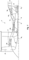
- turbojet engine 1 of the prior art which comprises, in a conventional manner, a fan S, a low pressure compressor BP 1a, an HP high pressure compressor 1b, a combustion chamber 1c, an HP high pressure turbine 1d and a LP low pressure turbine 1e.
- the high-pressure compressor 1b and the high-pressure turbine 1d are connected by a high-pressure shaft 4 and form with it an HP high-pressure body.
- the low pressure compressor 1a and the low pressure turbine 1e are connected by a low pressure shaft 5 and form with it a low pressure body LP.
- These bodies are carried by fixed structural parts, called intermediate housing 2 for the support of their bearings located upstream and exhaust housing 3 for the support of their bearings downstream.
- a turbomachine thus comprises, generally, an upstream enclosure E1 associated with the intermediate casing 2 and a downstream enclosure E2 associated with the exhaust casing 3. As indicated above these enclosures are bathed in an atmosphere containing oil for the lubrication of the various organs and they are traversed by a controlled flow of air for pressurizing purposes.
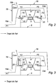
- FIG. 2 there is shown a bearing in its enclosure according to an arrangement of the prior art. This is the rear bearing associated with the exhaust casing with its enclosure E2.
- the downstream end of the LP shaft 5 is supported by a bearing 7 whose fixed ring 7a is mounted in a bearing support 9 integral with the exhaust casing of the engine.
- the bearing is bathed in an oil mist produced by means not shown.
- the bearing support 9 is shaped so as to arrange with the shaft an enclosure E2 enveloping the bearing 7.
- the bearing support forms a fixed wall 9.
- At the upstream of the bearing a first seal 10 seals between the fixed wall 9 and the shaft 5.
- a second seal 20 seals between the support and the shaft 5.
- the first seal is here a segmented radial seal the second seal Sealing is a labyrinth seal.
- the bearing support 9 comprises a wall portion 16 upstream which extends perpendicularly to the shaft 5.
- the second labyrinth seal 20 comprises wipers cooperating with an element of abradable material. A spin as for the first seal brings back to the enclosure oil that tends to accumulate against the seal.
- the arrows indicate the circulation of the pressurizing air of the joints.
- the air F1 coming from the compressors enters through an opening 19a close to the shaft 5 in the chamber Cam formed between the upstream wall of the enclosure E2 and a stator element 19 such as a sheet.
- This air swirls inside this chamber because of the rotation of the shaft 5. It undergoes a swirling compression, or a vortex recompression and escapes partly in F2 through the exhaust opening 19b, remote of the shaft, formed by the annular channel formed between the enclosure E2 and the sheet 19.
- the pressure is determined so that a portion F10 of the air in this chamber Cam passes through the first seal 10 in the bearing housing so as to prevent any leakage of oil through this seal.
- the air F2 follows a path F3 then F4 into the downstream chamber Cav on the side of the second bearing seal 20. Part F20 of the air passes through the seal 20.
- the air pressure increases from F1 to F2, as indicated above, then decreases in F3 to F4 due to pressure losses in the circuit between the two rooms Cam and Cav. It can be seen that in this configuration the pressure in Ajuste upstream of the first seal 10 remains lower than the pressure at B just at the inlet of the second seal despite the pressure losses at F3 and F4.
- the pressure at B is at a level sufficient relative to the pressure inside the chamber to prevent the oil from escaping through the labyrinth seal 20.
- the figure 3 shows the arrangement of the invention.
- a plate 30 has been mounted, with interposition of a spacer 32, on the wall portion 16 of the bearing support 9.
- This plate 30 defines a passage forming said air guide means which extends radially between the shaft 5 and the annular outlet channel 19b of the chamber Cam.
- a small clearance J is present between the shaft 5 and the plate 30.
- the sheet In addition to the pressure increase upstream of the first seal, the sheet also has the advantage of avoiding the pressure variations that can occur in the cam chamber at all radial heights. These variations in undesirable pressures can be caused by the shape of the housing and the force of the vortex. The pressure obtained upstream of the joint is in this way only slightly subject to variations in its environment.
- the pressure recovery is further improved by straightening the centripetal air flow.
- rectifying means which cancel or at least reduce the tangential component of speed of the centripetal air flow.
- These flux rectifying means are, for example, suitably oriented orifices, for example of oblong shape, formed in the spacer 32. Instead of orifices, radial fins or any other means may be provided, a honeycomb ring for example. example.
- the figure 4 shows an example of practical mounting with a segmented radial seal.
- the seal 10 comprises according to an embodiment as described in the patent EP 387122 a segmented ring 12, for example made of graphite, the segments of which are secured by means of an elastic ring and are housed in a groove of an annular seal support plate 16. The segments bear against an annular track arranged on the surface of the tree.
- the joint support plate 16 forms the upstream portion of the bearing enclosure.
- the joint support plate 16 extends in a plane transverse to the shaft, and is bolted to an upstream flange 18 of the bearing support 9.
- a swirler 14 is disposed downstream of the joint of which the function is to collect the oil that accumulates against the seal and guide it to the enclosure.
- the pressure generated by the vortex movement of the air is recovered to adjust the inlet pressure of the first seal. This pressure is adjusted to reduce and even virtually cancel the pressure difference with the inlet of the second seal downstream and thus balance the pressures across the bearing housing.
- the invention has been described in the case where it is necessary to adjust the pressure level immediately upstream of the upstream seal of the bearing housing of the low-pressure shaft of a double-body motor. However it is not limited to this application. It can be transposed to all cases where it is necessary to adjust the pressure at a seal of a bearing chamber and where there is a source of pressure nearby, in particular resulting from a recompression vortex .
Landscapes
- Engineering & Computer Science (AREA)
- Mechanical Engineering (AREA)
- General Engineering & Computer Science (AREA)
- Chemical & Material Sciences (AREA)
- Combustion & Propulsion (AREA)
- Sealing Using Fluids, Sealing Without Contact, And Removal Of Oil (AREA)
- Turbine Rotor Nozzle Sealing (AREA)
- Structures Of Non-Positive Displacement Pumps (AREA)
- Supercharger (AREA)
- Sealing Devices (AREA)
- Sealing Of Bearings (AREA)
Applications Claiming Priority (2)
| Application Number | Priority Date | Filing Date | Title |
|---|---|---|---|
| FR1450570A FR3016661B1 (fr) | 2014-01-23 | 2014-01-23 | Enceinte de palier d'une turbomachine |
| PCT/FR2015/050102 WO2015110744A1 (fr) | 2014-01-23 | 2015-01-15 | Enceinte de palier d'une turbomachine |
Publications (2)
| Publication Number | Publication Date |
|---|---|
| EP3097272A1 EP3097272A1 (fr) | 2016-11-30 |
| EP3097272B1 true EP3097272B1 (fr) | 2019-03-06 |
Family
ID=50729621
Family Applications (1)
| Application Number | Title | Priority Date | Filing Date |
|---|---|---|---|
| EP15704338.1A Active EP3097272B1 (fr) | 2014-01-23 | 2015-01-15 | Enceinte de palier d'une turbomachine |
Country Status (9)
| Country | Link |
|---|---|
| US (1) | US10502081B2 (ru) |
| EP (1) | EP3097272B1 (ru) |
| JP (1) | JP6535015B2 (ru) |
| CN (1) | CN105899763B (ru) |
| BR (1) | BR112016015612B1 (ru) |
| CA (1) | CA2935314C (ru) |
| FR (1) | FR3016661B1 (ru) |
| RU (1) | RU2685749C2 (ru) |
| WO (1) | WO2015110744A1 (ru) |
Families Citing this family (13)
| Publication number | Priority date | Publication date | Assignee | Title |
|---|---|---|---|---|
| FR3016661B1 (fr) * | 2014-01-23 | 2019-05-03 | Safran Aircraft Engines | Enceinte de palier d'une turbomachine |
| FR3049007B1 (fr) * | 2016-03-15 | 2019-05-10 | Safran Aircraft Engines | Turboreacteur ayant un groupe lubrification des paliers simplifie |
| FR3049006B1 (fr) * | 2016-03-15 | 2018-03-16 | Safran Aircraft Engines | Turboreacteur ayant un groupe lubrification des paliers simplifie |
| FR3062679B1 (fr) * | 2017-02-07 | 2019-04-19 | Safran Aircraft Engines | Virole de reduction de la surpression au voisinage du joint amont d'une enceinte de palier de turboreacteur |
| US10513938B2 (en) | 2017-04-25 | 2019-12-24 | United Technologies Corporation | Intershaft compartment buffering arrangement |
| FR3067057B1 (fr) * | 2017-05-30 | 2020-01-10 | Safran Aircraft Engines | Turbomachine comportant une enceinte a debits de fuite optimises |
| US10808573B1 (en) | 2019-03-29 | 2020-10-20 | Pratt & Whitney Canada Corp. | Bearing housing with flexible joint |
| US10844745B2 (en) | 2019-03-29 | 2020-11-24 | Pratt & Whitney Canada Corp. | Bearing assembly |
| CN112901351B (zh) * | 2019-12-03 | 2023-11-28 | 上海尚实能源科技有限公司 | 一种双转子燃气涡轮发动机轴承支撑结构 |
| FR3107561B1 (fr) | 2020-02-20 | 2022-02-18 | Safran Aircraft Engines | Optimisation de la pressurisation d’une enceinte de palier de turbomachine |
| CN113833573B (zh) * | 2020-06-24 | 2022-08-16 | 中国航发商用航空发动机有限责任公司 | 双转子双支点燃气轮机 |
| US11181008B1 (en) | 2020-07-17 | 2021-11-23 | Raytheon Technologies Corporation | Self-pressurized squeeze film damper |
| US11492926B2 (en) | 2020-12-17 | 2022-11-08 | Pratt & Whitney Canada Corp. | Bearing housing with slip joint |
Family Cites Families (22)
| Publication number | Priority date | Publication date | Assignee | Title |
|---|---|---|---|---|
| FR1261694A (fr) | 1959-07-02 | 1961-05-19 | Bayer Ag | Procédé de préparation d'esters thiophosphoniques |
| JPS4318420Y1 (ru) * | 1964-12-28 | 1968-07-30 | ||
| JPS5833702U (ja) * | 1981-08-31 | 1983-03-04 | 株式会社日立製作所 | 油切り輪の構造 |
| US4542623A (en) * | 1983-12-23 | 1985-09-24 | United Technologies Corporation | Air cooler for providing buffer air to a bearing compartment |
| JPS61119880A (ja) * | 1984-11-15 | 1986-06-07 | Ishikawajima Harima Heavy Ind Co Ltd | 回転機械の軸受ケ−スにおける油漏れ防止装置 |
| JPH0211274U (ru) * | 1988-07-07 | 1990-01-24 | ||
| US4989886A (en) * | 1988-12-30 | 1991-02-05 | Textron Inc. | Braided filamentary sealing element |
| FR2644205B1 (fr) | 1989-03-08 | 1991-05-03 | Snecma | Palier de turbomachine a joint d'etancheite integre |
| GB9306890D0 (en) * | 1993-04-01 | 1993-06-02 | Bmw Rolls Royce Gmbh | A gas turbine engine with bearing chambers and barrier air chambers |
| DE69919681T2 (de) * | 1999-05-26 | 2005-09-08 | Techspace Aero, Milmort | Dichtungsanordnung mit Auftrieb für Turbomaschinenlagergehäuse |
| DE19956919A1 (de) * | 1999-11-26 | 2001-05-31 | Rolls Royce Deutschland | Gasturbinen-Triebwerk mit einer Lagerkammer |
| US20030097872A1 (en) * | 2001-11-29 | 2003-05-29 | Granitz Charles Robert | System for reducing oil consumption in gas turbine engines |
| US7287384B2 (en) * | 2004-12-13 | 2007-10-30 | Pratt & Whitney Canada Corp. | Bearing chamber pressurization system |
| US7934901B2 (en) * | 2006-12-20 | 2011-05-03 | General Electric Company | Air directing assembly and method of assembling the same |
| FR2929325B1 (fr) | 2008-03-26 | 2012-09-28 | Snecma | Dispositif et procede d'equilibrage de pression dans une enceinte palier de turboreacteur |
| FR2952402B1 (fr) * | 2009-11-10 | 2015-10-30 | Snecma | Dispositif de deshuilage d'une enceinte dans une turbomachine |
| RU2414614C1 (ru) * | 2009-12-02 | 2011-03-20 | Открытое акционерное общество Авиамоторный научно-технический комплекс "Союз" | Турбореактивный двигатель с объединенной опорой турбины низкого и высокого давления |
| US20130192251A1 (en) * | 2012-01-31 | 2013-08-01 | Peter M. Munsell | Buffer system that communicates buffer supply air to one or more portions of a gas turbine engine |
| US9695709B2 (en) * | 2012-04-19 | 2017-07-04 | United Technologies Corporation | Electronic means for detecting buffered main shaft seal wear or failure in a turbine engine |
| US9353647B2 (en) * | 2012-04-27 | 2016-05-31 | General Electric Company | Wide discourager tooth |
| US9410429B2 (en) * | 2012-11-30 | 2016-08-09 | Pratt & Whitney Canada Corp. | Air cooling shaft at bearing interface |
| FR3016661B1 (fr) * | 2014-01-23 | 2019-05-03 | Safran Aircraft Engines | Enceinte de palier d'une turbomachine |
-
2014
- 2014-01-23 FR FR1450570A patent/FR3016661B1/fr active Active
-
2015
- 2015-01-15 JP JP2016546102A patent/JP6535015B2/ja active Active
- 2015-01-15 WO PCT/FR2015/050102 patent/WO2015110744A1/fr active Application Filing
- 2015-01-15 CA CA2935314A patent/CA2935314C/fr active Active
- 2015-01-15 US US15/110,905 patent/US10502081B2/en active Active
- 2015-01-15 BR BR112016015612-9A patent/BR112016015612B1/pt active IP Right Grant
- 2015-01-15 RU RU2016127794A patent/RU2685749C2/ru active
- 2015-01-15 EP EP15704338.1A patent/EP3097272B1/fr active Active
- 2015-01-15 CN CN201580004395.5A patent/CN105899763B/zh active Active
Non-Patent Citations (1)
| Title |
|---|
| None * |
Also Published As
| Publication number | Publication date |
|---|---|
| CA2935314C (fr) | 2022-03-08 |
| US10502081B2 (en) | 2019-12-10 |
| EP3097272A1 (fr) | 2016-11-30 |
| FR3016661A1 (fr) | 2015-07-24 |
| US20160341059A1 (en) | 2016-11-24 |
| CA2935314A1 (fr) | 2015-07-30 |
| CN105899763A (zh) | 2016-08-24 |
| BR112016015612B1 (pt) | 2022-10-04 |
| FR3016661B1 (fr) | 2019-05-03 |
| RU2016127794A3 (ru) | 2018-09-28 |
| RU2016127794A (ru) | 2018-03-01 |
| JP2017506299A (ja) | 2017-03-02 |
| CN105899763B (zh) | 2019-03-15 |
| WO2015110744A1 (fr) | 2015-07-30 |
| RU2685749C2 (ru) | 2019-04-23 |
| BR112016015612A2 (pt) | 2017-09-26 |
| JP6535015B2 (ja) | 2019-06-26 |
Similar Documents
| Publication | Publication Date | Title |
|---|---|---|
| EP3097272B1 (fr) | Enceinte de palier d'une turbomachine | |
| CA2671839C (fr) | Procede et systeme de lubrification d'une turbomachine | |
| EP2553221B1 (fr) | Dispositif d'étanchéité pour une enceinte d'huile d'un turboréacteur | |
| EP2788588B1 (fr) | Systeme pour assurer l'etancheite entre une enceinte d'huile et un volume exterieur attenant et turbomachine equipee d'un tel systeme d'etancheite | |
| FR2998922A1 (fr) | Etancheite d'enceintes de turbomachine realisee par joint a brosse et labyrinthe | |
| EP3112694B1 (fr) | Tambour perforé de compresseur de turbomachine axiale | |
| BE1023354B1 (fr) | Bec de separation degivrant de compresseur de turbomachine axiale | |
| EP2619419B1 (fr) | Systeme de pressurisation des enceintes de paliers des turbomachines par de l'air preleve dans la manche d'entree | |
| EP2803822B1 (fr) | Système de prélèvement d'air de turbomachine axiale | |
| EP2909450B1 (fr) | Trompe a jet pour depressuriser des enceintes de lubrification d'une turbomachine a doubles injecteurs independants | |
| CA2605947C (fr) | Canal de transition entre deux etages de turbine | |
| EP3462000B1 (fr) | Ensemble d'un support palier et des paliers d'un arbre de rotor dans une turbomachine | |
| FR3005099A1 (fr) | Structure de turbomachine comportant une bague de ventilation | |
| EP3728798B1 (fr) | Étanchéité dynamique entre deux rotors d'une turbomachine d'aéronef | |
| FR3067057A1 (fr) | Turbomachine comportant une enceinte a debits de fuite optimises | |
| FR3075867A1 (fr) | Dispositif de deshuilage d'une enceinte de lubrification de turbomachine | |
| EP2935897B1 (fr) | Assemblage d'étanchéité pour turbomachine | |
| FR3075252A1 (fr) | Ensemble d'etancheite | |
| FR3132732A1 (fr) | Turbomachine pour un aeronef |
Legal Events
| Date | Code | Title | Description |
|---|---|---|---|
| PUAI | Public reference made under article 153(3) epc to a published international application that has entered the european phase |
Free format text: ORIGINAL CODE: 0009012 |
|
| 17P | Request for examination filed |
Effective date: 20160804 |
|
| AK | Designated contracting states |
Kind code of ref document: A1 Designated state(s): AL AT BE BG CH CY CZ DE DK EE ES FI FR GB GR HR HU IE IS IT LI LT LU LV MC MK MT NL NO PL PT RO RS SE SI SK SM TR |
|
| AX | Request for extension of the european patent |
Extension state: BA ME |
|
| DAX | Request for extension of the european patent (deleted) | ||
| GRAP | Despatch of communication of intention to grant a patent |
Free format text: ORIGINAL CODE: EPIDOSNIGR1 |
|
| STAA | Information on the status of an ep patent application or granted ep patent |
Free format text: STATUS: GRANT OF PATENT IS INTENDED |
|
| INTG | Intention to grant announced |
Effective date: 20181001 |
|
| GRAS | Grant fee paid |
Free format text: ORIGINAL CODE: EPIDOSNIGR3 |
|
| GRAA | (expected) grant |
Free format text: ORIGINAL CODE: 0009210 |
|
| STAA | Information on the status of an ep patent application or granted ep patent |
Free format text: STATUS: THE PATENT HAS BEEN GRANTED |
|
| AK | Designated contracting states |
Kind code of ref document: B1 Designated state(s): AL AT BE BG CH CY CZ DE DK EE ES FI FR GB GR HR HU IE IS IT LI LT LU LV MC MK MT NL NO PL PT RO RS SE SI SK SM TR |
|
| REG | Reference to a national code |
Ref country code: GB Ref legal event code: FG4D Free format text: NOT ENGLISH |
|
| REG | Reference to a national code |
Ref country code: CH Ref legal event code: EP Ref country code: AT Ref legal event code: REF Ref document number: 1104820 Country of ref document: AT Kind code of ref document: T Effective date: 20190315 |
|
| REG | Reference to a national code |
Ref country code: DE Ref legal event code: R096 Ref document number: 602015025775 Country of ref document: DE |
|
| REG | Reference to a national code |
Ref country code: IE Ref legal event code: FG4D Free format text: LANGUAGE OF EP DOCUMENT: FRENCH |
|
| REG | Reference to a national code |
Ref country code: SE Ref legal event code: TRGR |
|
| REG | Reference to a national code |
Ref country code: NL Ref legal event code: MP Effective date: 20190306 |
|
| REG | Reference to a national code |
Ref country code: LT Ref legal event code: MG4D |
|
| PG25 | Lapsed in a contracting state [announced via postgrant information from national office to epo] |
Ref country code: LT Free format text: LAPSE BECAUSE OF FAILURE TO SUBMIT A TRANSLATION OF THE DESCRIPTION OR TO PAY THE FEE WITHIN THE PRESCRIBED TIME-LIMIT Effective date: 20190306 Ref country code: NO Free format text: LAPSE BECAUSE OF FAILURE TO SUBMIT A TRANSLATION OF THE DESCRIPTION OR TO PAY THE FEE WITHIN THE PRESCRIBED TIME-LIMIT Effective date: 20190606 Ref country code: FI Free format text: LAPSE BECAUSE OF FAILURE TO SUBMIT A TRANSLATION OF THE DESCRIPTION OR TO PAY THE FEE WITHIN THE PRESCRIBED TIME-LIMIT Effective date: 20190306 |
|
| PG25 | Lapsed in a contracting state [announced via postgrant information from national office to epo] |
Ref country code: BG Free format text: LAPSE BECAUSE OF FAILURE TO SUBMIT A TRANSLATION OF THE DESCRIPTION OR TO PAY THE FEE WITHIN THE PRESCRIBED TIME-LIMIT Effective date: 20190606 Ref country code: HR Free format text: LAPSE BECAUSE OF FAILURE TO SUBMIT A TRANSLATION OF THE DESCRIPTION OR TO PAY THE FEE WITHIN THE PRESCRIBED TIME-LIMIT Effective date: 20190306 Ref country code: RS Free format text: LAPSE BECAUSE OF FAILURE TO SUBMIT A TRANSLATION OF THE DESCRIPTION OR TO PAY THE FEE WITHIN THE PRESCRIBED TIME-LIMIT Effective date: 20190306 Ref country code: LV Free format text: LAPSE BECAUSE OF FAILURE TO SUBMIT A TRANSLATION OF THE DESCRIPTION OR TO PAY THE FEE WITHIN THE PRESCRIBED TIME-LIMIT Effective date: 20190306 Ref country code: NL Free format text: LAPSE BECAUSE OF FAILURE TO SUBMIT A TRANSLATION OF THE DESCRIPTION OR TO PAY THE FEE WITHIN THE PRESCRIBED TIME-LIMIT Effective date: 20190306 Ref country code: GR Free format text: LAPSE BECAUSE OF FAILURE TO SUBMIT A TRANSLATION OF THE DESCRIPTION OR TO PAY THE FEE WITHIN THE PRESCRIBED TIME-LIMIT Effective date: 20190607 |
|
| REG | Reference to a national code |
Ref country code: AT Ref legal event code: MK05 Ref document number: 1104820 Country of ref document: AT Kind code of ref document: T Effective date: 20190306 |
|
| PG25 | Lapsed in a contracting state [announced via postgrant information from national office to epo] |
Ref country code: ES Free format text: LAPSE BECAUSE OF FAILURE TO SUBMIT A TRANSLATION OF THE DESCRIPTION OR TO PAY THE FEE WITHIN THE PRESCRIBED TIME-LIMIT Effective date: 20190306 Ref country code: AL Free format text: LAPSE BECAUSE OF FAILURE TO SUBMIT A TRANSLATION OF THE DESCRIPTION OR TO PAY THE FEE WITHIN THE PRESCRIBED TIME-LIMIT Effective date: 20190306 Ref country code: PT Free format text: LAPSE BECAUSE OF FAILURE TO SUBMIT A TRANSLATION OF THE DESCRIPTION OR TO PAY THE FEE WITHIN THE PRESCRIBED TIME-LIMIT Effective date: 20190706 Ref country code: SK Free format text: LAPSE BECAUSE OF FAILURE TO SUBMIT A TRANSLATION OF THE DESCRIPTION OR TO PAY THE FEE WITHIN THE PRESCRIBED TIME-LIMIT Effective date: 20190306 Ref country code: EE Free format text: LAPSE BECAUSE OF FAILURE TO SUBMIT A TRANSLATION OF THE DESCRIPTION OR TO PAY THE FEE WITHIN THE PRESCRIBED TIME-LIMIT Effective date: 20190306 Ref country code: RO Free format text: LAPSE BECAUSE OF FAILURE TO SUBMIT A TRANSLATION OF THE DESCRIPTION OR TO PAY THE FEE WITHIN THE PRESCRIBED TIME-LIMIT Effective date: 20190306 Ref country code: CZ Free format text: LAPSE BECAUSE OF FAILURE TO SUBMIT A TRANSLATION OF THE DESCRIPTION OR TO PAY THE FEE WITHIN THE PRESCRIBED TIME-LIMIT Effective date: 20190306 |
|
| PG25 | Lapsed in a contracting state [announced via postgrant information from national office to epo] |
Ref country code: SM Free format text: LAPSE BECAUSE OF FAILURE TO SUBMIT A TRANSLATION OF THE DESCRIPTION OR TO PAY THE FEE WITHIN THE PRESCRIBED TIME-LIMIT Effective date: 20190306 Ref country code: PL Free format text: LAPSE BECAUSE OF FAILURE TO SUBMIT A TRANSLATION OF THE DESCRIPTION OR TO PAY THE FEE WITHIN THE PRESCRIBED TIME-LIMIT Effective date: 20190306 |
|
| REG | Reference to a national code |
Ref country code: DE Ref legal event code: R097 Ref document number: 602015025775 Country of ref document: DE |
|
| PG25 | Lapsed in a contracting state [announced via postgrant information from national office to epo] |
Ref country code: IS Free format text: LAPSE BECAUSE OF FAILURE TO SUBMIT A TRANSLATION OF THE DESCRIPTION OR TO PAY THE FEE WITHIN THE PRESCRIBED TIME-LIMIT Effective date: 20190706 Ref country code: AT Free format text: LAPSE BECAUSE OF FAILURE TO SUBMIT A TRANSLATION OF THE DESCRIPTION OR TO PAY THE FEE WITHIN THE PRESCRIBED TIME-LIMIT Effective date: 20190306 |
|
| PLBE | No opposition filed within time limit |
Free format text: ORIGINAL CODE: 0009261 |
|
| STAA | Information on the status of an ep patent application or granted ep patent |
Free format text: STATUS: NO OPPOSITION FILED WITHIN TIME LIMIT |
|
| PG25 | Lapsed in a contracting state [announced via postgrant information from national office to epo] |
Ref country code: DK Free format text: LAPSE BECAUSE OF FAILURE TO SUBMIT A TRANSLATION OF THE DESCRIPTION OR TO PAY THE FEE WITHIN THE PRESCRIBED TIME-LIMIT Effective date: 20190306 |
|
| 26N | No opposition filed |
Effective date: 20191209 |
|
| PG25 | Lapsed in a contracting state [announced via postgrant information from national office to epo] |
Ref country code: SI Free format text: LAPSE BECAUSE OF FAILURE TO SUBMIT A TRANSLATION OF THE DESCRIPTION OR TO PAY THE FEE WITHIN THE PRESCRIBED TIME-LIMIT Effective date: 20190306 |
|
| PG25 | Lapsed in a contracting state [announced via postgrant information from national office to epo] |
Ref country code: TR Free format text: LAPSE BECAUSE OF FAILURE TO SUBMIT A TRANSLATION OF THE DESCRIPTION OR TO PAY THE FEE WITHIN THE PRESCRIBED TIME-LIMIT Effective date: 20190306 |
|
| PG25 | Lapsed in a contracting state [announced via postgrant information from national office to epo] |
Ref country code: MC Free format text: LAPSE BECAUSE OF FAILURE TO SUBMIT A TRANSLATION OF THE DESCRIPTION OR TO PAY THE FEE WITHIN THE PRESCRIBED TIME-LIMIT Effective date: 20190306 |
|
| REG | Reference to a national code |
Ref country code: CH Ref legal event code: PL |
|
| REG | Reference to a national code |
Ref country code: BE Ref legal event code: MM Effective date: 20200131 |
|
| PG25 | Lapsed in a contracting state [announced via postgrant information from national office to epo] |
Ref country code: LU Free format text: LAPSE BECAUSE OF NON-PAYMENT OF DUE FEES Effective date: 20200115 |
|
| PG25 | Lapsed in a contracting state [announced via postgrant information from national office to epo] |
Ref country code: LI Free format text: LAPSE BECAUSE OF NON-PAYMENT OF DUE FEES Effective date: 20200131 Ref country code: BE Free format text: LAPSE BECAUSE OF NON-PAYMENT OF DUE FEES Effective date: 20200131 Ref country code: CH Free format text: LAPSE BECAUSE OF NON-PAYMENT OF DUE FEES Effective date: 20200131 |
|
| PG25 | Lapsed in a contracting state [announced via postgrant information from national office to epo] |
Ref country code: IE Free format text: LAPSE BECAUSE OF NON-PAYMENT OF DUE FEES Effective date: 20200115 |
|
| PG25 | Lapsed in a contracting state [announced via postgrant information from national office to epo] |
Ref country code: MT Free format text: LAPSE BECAUSE OF FAILURE TO SUBMIT A TRANSLATION OF THE DESCRIPTION OR TO PAY THE FEE WITHIN THE PRESCRIBED TIME-LIMIT Effective date: 20190306 Ref country code: CY Free format text: LAPSE BECAUSE OF FAILURE TO SUBMIT A TRANSLATION OF THE DESCRIPTION OR TO PAY THE FEE WITHIN THE PRESCRIBED TIME-LIMIT Effective date: 20190306 |
|
| PG25 | Lapsed in a contracting state [announced via postgrant information from national office to epo] |
Ref country code: MK Free format text: LAPSE BECAUSE OF FAILURE TO SUBMIT A TRANSLATION OF THE DESCRIPTION OR TO PAY THE FEE WITHIN THE PRESCRIBED TIME-LIMIT Effective date: 20190306 |
|
| PGFP | Annual fee paid to national office [announced via postgrant information from national office to epo] |
Ref country code: IT Payment date: 20230103 Year of fee payment: 9 |
|
| PGFP | Annual fee paid to national office [announced via postgrant information from national office to epo] |
Ref country code: GB Payment date: 20231219 Year of fee payment: 10 |
|
| PGFP | Annual fee paid to national office [announced via postgrant information from national office to epo] |
Ref country code: SE Payment date: 20231219 Year of fee payment: 10 Ref country code: FR Payment date: 20231219 Year of fee payment: 10 |
|
| PGFP | Annual fee paid to national office [announced via postgrant information from national office to epo] |
Ref country code: DE Payment date: 20231219 Year of fee payment: 10 |