EP3097265B1 - Well tools having magnetic shielding for magnetic sensor - Google Patents
Well tools having magnetic shielding for magnetic sensor Download PDFInfo
- Publication number
- EP3097265B1 EP3097265B1 EP14887161.9A EP14887161A EP3097265B1 EP 3097265 B1 EP3097265 B1 EP 3097265B1 EP 14887161 A EP14887161 A EP 14887161A EP 3097265 B1 EP3097265 B1 EP 3097265B1
- Authority
- EP
- European Patent Office
- Prior art keywords
- magnetic
- sensor
- shield
- magnetic field
- magnetic sensor
- Prior art date
- Legal status (The legal status is an assumption and is not a legal conclusion. Google has not performed a legal analysis and makes no representation as to the accuracy of the status listed.)
- Active
Links
- 230000005291 magnetic effect Effects 0.000 title claims description 386
- 230000035699 permeability Effects 0.000 claims description 25
- 230000004888 barrier function Effects 0.000 claims description 22
- 239000000463 material Substances 0.000 claims description 19
- 239000012530 fluid Substances 0.000 description 32
- 238000002347 injection Methods 0.000 description 27
- 239000007924 injection Substances 0.000 description 27
- 238000000034 method Methods 0.000 description 14
- 238000007789 sealing Methods 0.000 description 14
- 230000015572 biosynthetic process Effects 0.000 description 12
- 238000001514 detection method Methods 0.000 description 12
- 238000005755 formation reaction Methods 0.000 description 12
- 230000004044 response Effects 0.000 description 11
- 230000008859 change Effects 0.000 description 8
- 206010017076 Fracture Diseases 0.000 description 7
- 238000004891 communication Methods 0.000 description 5
- PXHVJJICTQNCMI-UHFFFAOYSA-N Nickel Chemical compound [Ni] PXHVJJICTQNCMI-UHFFFAOYSA-N 0.000 description 4
- 238000006073 displacement reaction Methods 0.000 description 4
- 230000004907 flux Effects 0.000 description 4
- 230000009286 beneficial effect Effects 0.000 description 3
- 230000008901 benefit Effects 0.000 description 3
- 239000002889 diamagnetic material Substances 0.000 description 3
- 230000005415 magnetization Effects 0.000 description 3
- 229910052751 metal Inorganic materials 0.000 description 3
- 239000002184 metal Substances 0.000 description 3
- 230000002441 reversible effect Effects 0.000 description 3
- 229910001220 stainless steel Inorganic materials 0.000 description 3
- XEEYBQQBJWHFJM-UHFFFAOYSA-N Iron Chemical compound [Fe] XEEYBQQBJWHFJM-UHFFFAOYSA-N 0.000 description 2
- 208000006670 Multiple fractures Diseases 0.000 description 2
- 229910000831 Steel Inorganic materials 0.000 description 2
- 230000003044 adaptive effect Effects 0.000 description 2
- 229910045601 alloy Inorganic materials 0.000 description 2
- 239000000956 alloy Substances 0.000 description 2
- 239000003990 capacitor Substances 0.000 description 2
- 230000006872 improvement Effects 0.000 description 2
- 229910001026 inconel Inorganic materials 0.000 description 2
- 230000000977 initiatory effect Effects 0.000 description 2
- 230000005389 magnetism Effects 0.000 description 2
- 229910052759 nickel Inorganic materials 0.000 description 2
- 230000000717 retained effect Effects 0.000 description 2
- 239000004576 sand Substances 0.000 description 2
- 239000010959 steel Substances 0.000 description 2
- 230000000638 stimulation Effects 0.000 description 2
- 238000006467 substitution reaction Methods 0.000 description 2
- 229920000049 Carbon (fiber) Polymers 0.000 description 1
- VYZAMTAEIAYCRO-UHFFFAOYSA-N Chromium Chemical compound [Cr] VYZAMTAEIAYCRO-UHFFFAOYSA-N 0.000 description 1
- 229910000976 Electrical steel Inorganic materials 0.000 description 1
- 230000005355 Hall effect Effects 0.000 description 1
- ZOKXTWBITQBERF-UHFFFAOYSA-N Molybdenum Chemical compound [Mo] ZOKXTWBITQBERF-UHFFFAOYSA-N 0.000 description 1
- 238000010795 Steam Flooding Methods 0.000 description 1
- 238000007792 addition Methods 0.000 description 1
- 229910052782 aluminium Inorganic materials 0.000 description 1
- XAGFODPZIPBFFR-UHFFFAOYSA-N aluminium Chemical compound [Al] XAGFODPZIPBFFR-UHFFFAOYSA-N 0.000 description 1
- 230000006399 behavior Effects 0.000 description 1
- 229910052797 bismuth Inorganic materials 0.000 description 1
- JCXGWMGPZLAOME-UHFFFAOYSA-N bismuth atom Chemical compound [Bi] JCXGWMGPZLAOME-UHFFFAOYSA-N 0.000 description 1
- 239000004917 carbon fiber Substances 0.000 description 1
- 229910052804 chromium Inorganic materials 0.000 description 1
- 239000011651 chromium Substances 0.000 description 1
- 239000011248 coating agent Substances 0.000 description 1
- 238000000576 coating method Methods 0.000 description 1
- 239000002131 composite material Substances 0.000 description 1
- 230000008878 coupling Effects 0.000 description 1
- 238000010168 coupling process Methods 0.000 description 1
- 238000005859 coupling reaction Methods 0.000 description 1
- 238000012217 deletion Methods 0.000 description 1
- 230000037430 deletion Effects 0.000 description 1
- 238000005553 drilling Methods 0.000 description 1
- 230000000694 effects Effects 0.000 description 1
- 230000005611 electricity Effects 0.000 description 1
- 238000011156 evaluation Methods 0.000 description 1
- 239000002360 explosive Substances 0.000 description 1
- 239000011554 ferrofluid Substances 0.000 description 1
- 230000005294 ferromagnetic effect Effects 0.000 description 1
- 239000003302 ferromagnetic material Substances 0.000 description 1
- 239000007789 gas Substances 0.000 description 1
- 239000000499 gel Substances 0.000 description 1
- 230000006698 induction Effects 0.000 description 1
- 230000001939 inductive effect Effects 0.000 description 1
- 239000011261 inert gas Substances 0.000 description 1
- 238000009434 installation Methods 0.000 description 1
- 230000002452 interceptive effect Effects 0.000 description 1
- 229910052742 iron Inorganic materials 0.000 description 1
- 230000000670 limiting effect Effects 0.000 description 1
- 238000003754 machining Methods 0.000 description 1
- 238000004519 manufacturing process Methods 0.000 description 1
- 150000002739 metals Chemical class 0.000 description 1
- 229910000697 metglas Inorganic materials 0.000 description 1
- VNWKTOKETHGBQD-UHFFFAOYSA-N methane Chemical compound C VNWKTOKETHGBQD-UHFFFAOYSA-N 0.000 description 1
- 238000012986 modification Methods 0.000 description 1
- 230000004048 modification Effects 0.000 description 1
- 229910052750 molybdenum Inorganic materials 0.000 description 1
- 239000011733 molybdenum Substances 0.000 description 1
- 229910000595 mu-metal Inorganic materials 0.000 description 1
- 239000003921 oil Substances 0.000 description 1
- 238000012856 packing Methods 0.000 description 1
- 229910000889 permalloy Inorganic materials 0.000 description 1
- 239000004033 plastic Substances 0.000 description 1
- 229920003023 plastic Polymers 0.000 description 1
- 239000002296 pyrolytic carbon Substances 0.000 description 1
- 238000010008 shearing Methods 0.000 description 1
- 230000003068 static effect Effects 0.000 description 1
- 239000000126 substance Substances 0.000 description 1
- 239000002887 superconductor Substances 0.000 description 1
- 230000002618 waking effect Effects 0.000 description 1
- XLYOFNOQVPJJNP-UHFFFAOYSA-N water Substances O XLYOFNOQVPJJNP-UHFFFAOYSA-N 0.000 description 1
Images


Classifications
-
- E—FIXED CONSTRUCTIONS
- E21—EARTH DRILLING; MINING
- E21B—EARTH DRILLING, e.g. DEEP DRILLING; OBTAINING OIL, GAS, WATER, SOLUBLE OR MELTABLE MATERIALS OR A SLURRY OF MINERALS FROM WELLS
- E21B47/00—Survey of boreholes or wells
- E21B47/09—Locating or determining the position of objects in boreholes or wells, e.g. the position of an extending arm; Identifying the free or blocked portions of pipes
- E21B47/092—Locating or determining the position of objects in boreholes or wells, e.g. the position of an extending arm; Identifying the free or blocked portions of pipes by detecting magnetic anomalies
-
- E—FIXED CONSTRUCTIONS
- E21—EARTH DRILLING; MINING
- E21B—EARTH DRILLING, e.g. DEEP DRILLING; OBTAINING OIL, GAS, WATER, SOLUBLE OR MELTABLE MATERIALS OR A SLURRY OF MINERALS FROM WELLS
- E21B23/00—Apparatus for displacing, setting, locking, releasing, or removing tools, packers or the like in the boreholes or wells
-
- E—FIXED CONSTRUCTIONS
- E21—EARTH DRILLING; MINING
- E21B—EARTH DRILLING, e.g. DEEP DRILLING; OBTAINING OIL, GAS, WATER, SOLUBLE OR MELTABLE MATERIALS OR A SLURRY OF MINERALS FROM WELLS
- E21B34/00—Valve arrangements for boreholes or wells
- E21B34/06—Valve arrangements for boreholes or wells in wells
- E21B34/10—Valve arrangements for boreholes or wells in wells operated by control fluid supplied from outside the borehole
- E21B34/102—Valve arrangements for boreholes or wells in wells operated by control fluid supplied from outside the borehole with means for locking the closing element in open or closed position
- E21B34/103—Valve arrangements for boreholes or wells in wells operated by control fluid supplied from outside the borehole with means for locking the closing element in open or closed position with a shear pin
-
- E—FIXED CONSTRUCTIONS
- E21—EARTH DRILLING; MINING
- E21B—EARTH DRILLING, e.g. DEEP DRILLING; OBTAINING OIL, GAS, WATER, SOLUBLE OR MELTABLE MATERIALS OR A SLURRY OF MINERALS FROM WELLS
- E21B47/00—Survey of boreholes or wells
- E21B47/01—Devices for supporting measuring instruments on drill bits, pipes, rods or wirelines; Protecting measuring instruments in boreholes against heat, shock, pressure or the like
- E21B47/017—Protecting measuring instruments
-
- E—FIXED CONSTRUCTIONS
- E21—EARTH DRILLING; MINING
- E21B—EARTH DRILLING, e.g. DEEP DRILLING; OBTAINING OIL, GAS, WATER, SOLUBLE OR MELTABLE MATERIALS OR A SLURRY OF MINERALS FROM WELLS
- E21B2200/00—Special features related to earth drilling for obtaining oil, gas or water
- E21B2200/06—Sleeve valves
Definitions
- This disclosure relates generally to equipment utilized and operations performed in conjunction with a subterranean well and, in an example described below, more particularly provides for magnetic sensing in well tools.
- US 2008/265892 A1 discloses an externally guided and directed field induction resistivity tool.
- US 2013/264051 A1 discloses well tools selectively responsive to magnetic patterns.
- US 4,901,069 A discloses an apparatus for electromagnetically coupling power and data signals between a first unit and a second unit and in particular between well bore apparatus and the surface.
- US 5,138,263 A discloses an electromagnetic formation evaluation tool.
- US 5 130 655 A discloses multiple-coil magnetic field sensor with series-connected main coils and parallel-connected feedback coils.
- US 2013/314092 A1 discloses sensing the magnetic field of the earth.
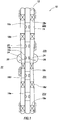
- FIG. 1 Representatively illustrated in FIG. 1 is a system 10 for use with a well, and an associated method, which can embody principles of this disclosure.
- a tubular string 12 is positioned in a wellbore 14, with the tubular string having multiple injection valves 16a-e and packers 18a-e interconnected therein.
- the tubular string 12 may be of the type known to those skilled in the art as casing, liner, tubing, a production string, a work string, a drill string, etc. Any type of tubular string may be used and remain within the scope of this disclosure.
- the packers 18a-e seal off an annulus 20 formed radially between the tubular string 12 and the wellbore 14.
- the packers 18a-e in this example are designed for sealing engagement with an uncased or open hole wellbore 14, but if the wellbore is cased or lined, then cased hole-type packers may be used instead.
- Swellable, inflatable, expandable and other types of packers may be used, as appropriate for the well conditions, or no packers may be used (for example, the tubular string 12 could be expanded into contact with the wellbore 14, the tubular string could be cemented in the wellbore, etc.).
- the injection valves 16a-e permit selective fluid communication between an interior of the tubular string 12 and each section of the annulus 20 isolated between two of the packers 18a-e. Each section of the annulus 20 is in fluid communication with a corresponding earth formation zone 22a-d.
- the injection valves 16a-e can otherwise be placed in communication with the individual zones 22a-d, for example, with perforations, etc.
- the zones 22a-d may be sections of a same formation 22, or they may be sections of different formations. Each zone 22a-d may be associated with one or more of the injection valves 16a-e.
- two injection valves 16b,c are associated with the section of the annulus 20 isolated between the packers 18b,c, and this section of the annulus is in communication with the associated zone 22b. It will be appreciated that any number of injection valves may be associated with a zone.
- the multiple injection valves can provide for injecting fluid 24 at multiple fracture initiation points along the wellbore 14.
- the valve 16c has been opened, and fluid 24 is being injected into the zone 22b, thereby forming the fractures 26.
- valves 16a,b,d,e are closed while the fluid 24 is being flowed out of the valve 16c and into the zone 22b. This enables all of the fluid 24 flow to be directed toward forming the fractures 26, with enhanced control over the operation at that particular location.
- valves 16a-e could be open while the fluid 24 is flowed into a zone of an earth formation 22.
- both of the valves 16b,c could be open while the fluid 24 is flowed into the zone 22b. This would enable fractures to be formed at multiple fracture initiation locations corresponding to the open valves.
- valves 16a-e it would be beneficial to be able to open different sets of one or more of the valves 16a-e at different times.
- one set such as valves 16b,c
- another set such as valve 16a
- another time such as, when it is desired to form fractures into the zone 22a
- One or more sets of the valves 16a-e could be open simultaneously. However, it is generally preferable for only one set of the valves 16a-e to be open at a time, so that the fluid 24 flow can be concentrated on a particular zone, and so flow into that zone can be individually controlled.
- the fluid 24 could be any type of fluid which is injected into an earth formation, e.g., for stimulation, conformance, acidizing, fracturing, water-flooding, steam-flooding, treatment, gravel packing, cementing, or any other purpose.
- the principles of this disclosure are applicable to many different types of well systems and operations.
- the principles of this disclosure could be applied in circumstances where fluid is not only injected, but is also (or only) produced from the formation 22.
- the fluid 24 could be oil, gas, water, etc., produced from the formation 22.
- well tools other than injection valves can benefit from the principles described herein.
- FIG. 2 an enlarged scale cross-sectional view of one example of the injection valve 16 is representatively illustrated.
- the injection valve 16 of FIG. 2 may be used in the well system 10 and method of FIG. 1 , or it may be used in other well systems and methods, while still remaining within the scope of this disclosure.
- the valve 16 includes openings 28 in a sidewall of a generally tubular housing 30.
- the openings 28 are blocked by a sleeve 32, which is retained in position by shear members 34.
- valve 16 In this configuration, fluid communication is prevented between the annulus 20 external to the valve 16, and an internal flow passage 36 which extends longitudinally through the valve (and which extends longitudinally through the tubular string 12 when the valve is interconnected therein).
- the valve 16 can be opened, however, by shearing the shear members 34 and displacing the sleeve 32 (downward as viewed in FIG. 2 ) to a position in which the sleeve does not block the openings 28.
- a magnetic device 38 is displaced into the valve to activate an actuator 50 thereof.
- the magnetic device 38 is depicted in FIG. 2 as being generally cylindrical, but other shapes and types of magnetic devices (such as, balls, darts, plugs, wipers, fluids, gels, etc.) may be used in other examples.
- a ferrofluid, magnetorheological fluid, or any other fluid having magnetic properties which can be sensed by the sensor 40 could be pumped to or past the sensor in order to transmit a magnetic signal to the actuator 50.
- the magnetic device 38 may be displaced into the valve 16 by any technique.
- the magnetic device 38 can be dropped through the tubular string 12, pumped by flowing fluid through the passage 36, self-propelled, conveyed by wireline, slickline, coiled tubing, jointed tubing, etc.
- the magnetic device 38 has known magnetic properties, and/or produces a known magnetic field, or pattern or combination of magnetic fields, which is/are detected by a magnetic sensor 40 of the valve 16.
- the magnetic sensor 40 can be any type of sensor which is capable of detecting the presence of the magnetic field(s) produced by the magnetic device 38, and/or one or more other magnetic properties of the magnetic device.
- Suitable sensors include (but are not limited to) giant magneto-resistive (GMR) sensors, Hall-effect sensors, conductive coils, a super conductive quantum interference device (SQUID), etc.
- Permanent magnets can be combined with the magnetic sensor 40 in order to create a magnetic field that is disturbed by the magnetic device 38. A change in the magnetic field can be detected by the sensor 40 as an indication of the presence of the magnetic device 38.
- the sensor 40 is connected to electronic circuitry 42 which determines whether the sensor has detected a particular predetermined magnetic field, or pattern or combination of magnetic fields, magnetic permittivity or other magnetic properties of the magnetic device 38.
- the electronic circuitry 42 could have the predetermined magnetic field(s), magnetic permittivity or other magnetic properties programmed into non-volatile memory for comparison to magnetic fields/properties detected by the sensor 40.
- the electronic circuitry 42 could be supplied with electrical power via an on-board battery, a downhole generator, or any other electrical power source.
- the electronic circuitry 42 could include a capacitor, wherein an electrical resonance behavior between the capacitance of the capacitor and the magnetic sensor 40 changes, depending on whether the magnetic device 38 is present.
- the electronic circuitry 42 could include an adaptive magnetic field that adjusts to a baseline magnetic field of the surrounding environment (e.g., the formation 22, surrounding metallic structures, etc.). The electronic circuitry 42 could determine whether the measured magnetic fields exceed the adaptive magnetic field level.
- the senor 40 could comprise an inductive sensor which can detect the presence of a metallic device (e.g., by detecting a change in a magnetic field, etc.).
- the metallic device (such as a metal ball or dart, etc.) can be considered a magnetic device 38, in the sense that it conducts a magnetic field and produces changes in a magnetic field which can be detected by the sensor 40.
- the electronic circuitry 42 determines that the sensor 40 has detected the predetermined magnetic field(s) or change(s) in magnetic field(s), the electronic circuitry causes a valve device 44 to open.
- the valve device 44 includes a piercing member 46 which pierces a pressure barrier 48.
- the piercing member 46 can be driven by any means, such as, by an electrical, hydraulic, mechanical, explosive, chemical or other type of actuator.
- Other types of valve devices 44 such as those described in US patent application no. 12/688058 and in U.S. patent no. 8235103 ) may be used, in keeping with the scope of this disclosure.
- a piston 52 on a mandrel 54 becomes unbalanced (e.g., a pressure differential is created across the piston), and the piston displaces downward as viewed in FIG. 2 .
- This displacement of the piston 52 could, in some examples, be used to shear the shear members 34 and displace the sleeve 32 to its open position.
- the piston 52 displacement is used to activate a retractable seat 56 to a sealing position thereof.
- the retractable seat 56 is in the form of resilient collets 58 which are initially received in an annular recess 60 formed in the housing 30. In this position, the retractable seat 56 is retracted, and is not capable of sealingly engaging the magnetic device 38 or any other form of plug in the flow passage 36.
- a time delay could be provided between the sensor 40 detecting the predetermined magnetic field or change in magnetic filed, and the piercing member 46 opening the valve device 44. Such a time delay could be programmed in the electronic circuitry 42.
- a plug (such as, a ball, a dart, a magnetic device 38, etc.) can sealingly engage the seat 56, and increased pressure can be applied to the passage 36 above the plug to thereby shear the shear members 34 and downwardly displace the sleeve 32 to its open position.
- the retractable seat 56 may be sealingly engaged by the magnetic device 38 which initially activates the actuator 50 (e.g., in response to the sensor 40 detecting the predetermined magnetic field(s) or change(s) in magnetic field(s) produced by the magnetic device), or the retractable seat may be sealingly engaged by another magnetic device and/or plug subsequently displaced into the valve 16.
- the retractable seat 56 may be actuated to its sealing position in response to displacement of more than one magnetic device 38 into the valve 16.
- the electronic circuitry 42 may not actuate the valve device 44 until a predetermined number of the magnetic devices 38 have been displaced into the valve 16, and/or until a predetermined spacing in time is detected, etc.
- FIGS. 3-6 another example of the injection valve 16 is representatively illustrated.
- the sleeve 32 is initially in a closed position, as depicted in FIG. 3 .
- the sleeve 32 is displaced to its open position (see FIG. 4 ) when a support fluid 63 is flowed from one chamber 64 to another chamber 66.
- the chambers 64, 66 are initially isolated from each other by the pressure barrier 48.
- the sensor 40 detects the predetermined magnetic signal(s) produced by the magnetic device(s) 38
- the piercing member 46 pierces the pressure barrier 48, and the support fluid 63 flows from the chamber 64 to the chamber 66, thereby allowing a pressure differential across the sleeve 32 to displace the sleeve downward to its open position, as depicted in FIG. 4 .
- Fluid 24 can now be flowed outward through the openings 28 from the passage 36 to the annulus 20.
- the retractable seat 56 is now extended inwardly to its sealing position.
- the retractable seat 56 is in the form of an expandable ring which is extended radially inward to its sealing position by the downward displacement of the sleeve 32.
- the magnetic device 38 in this example comprises a ball or sphere.
- one or more permanent magnets 68 or other type of magnetic field-producing components are included in the magnetic device 38.
- the magnetic device 38 is retrieved from the passage 36 by reverse flow of fluid through the passage 36 (e.g., upward flow as viewed in FIG. 5 ).
- the magnetic device 38 is conveyed upwardly through the passage 36 by this reverse flow, and eventually engages in sealing contact with the seat 56, as depicted in FIG. 5 .
- a pressure differential across the magnetic device 38 and seat 56 causes them to be displaced upward against a downward biasing force exerted by a spring 70 on a retainer sleeve 72.
- the magnetic device 38, seat 56 and sleeve 72 are displaced upward, thereby allowing the seat 56 to expand outward to its retracted position, and allowing the magnetic device 38 to be conveyed upward through the passage 36, e.g., for retrieval to the surface.
- the seat 58 is initially expanded or "retracted” from its sealing position, and is later deflected inward to its sealing position. In the FIGS. 3-6 example, the seat 58 can then be again expanded (see FIG. 6 ) for retrieval of the magnetic device 38 (or to otherwise minimize obstruction of the passage 36).
- the seat 58 in both of these examples can be considered “retractable,” in that the seat can be in its inward sealing position, or in its outward non-sealing position, when desired.
- the seat 58 can be in its non-sealing position when initially installed, and then can be actuated to its sealing position (e.g., in response to detection of a predetermined pattern or combination of magnetic fields), without later being actuated to its sealing position again, and still be considered a "retractable" seat.
- FIGS. 7 & 8 another example of the magnetic device 38 is representatively illustrated.
- magnets (not shown in FIGS. 7 & 8 , see, e.g., permanent magnet 68 in FIG. 4 ) are retained in recesses 74 formed in an outer surface of a sphere 76.
- the recesses 74 are arranged in a pattern which, in this case, resembles that of stitching on a baseball.
- the pattern comprises spaced apart positions distributed along a continuous undulating path about the sphere 76.
- any pattern of magnetic field-producing components may be used in the magnetic device 38, in keeping with the scope of this disclosure.
- the magnetic field-producing components could be arranged in lines from one side of the sphere 76 to an opposite side.
- the magnets 68 are preferably arranged to provide a magnetic field a substantial distance from the device 38, and to do so no matter the orientation of the sphere 76.
- the pattern depicted in FIGS. 7 & 8 desirably projects the produced magnetic field(s) substantially evenly around the sphere 76.
- the pattern can desirably project the produced magnetic field(s) in at least one axis around the sphere 76.
- the magnetic field(s) may not be even, but can point in different directions.
- the magnetic field(s) are detectable all around the sphere 76.
- the magnetic field(s) may be produced by permanent magnets, electromagnets, a combination, etc. Any type of magnetic field producing components may be used in the magnetic device 38.
- the magnetic field(s) produced by the magnetic device 38 may vary, for example, to transmit data, information, commands, etc., or to generate electrical power (e.g., in a coil through which the magnetic field passes).
- the actuator 50 includes two of the valve devices 44.
- valve devices 44 When one of the valve devices 44 opens, a sufficient amount of the support fluid 63 is drained to displace the sleeve 32 to its open position (similar to, e.g., FIG. 4 ), in which the fluid 24 can be flowed outward through the openings 28.
- the other valve device 44 opens, more of the support fluid 63 is drained, thereby further displacing the sleeve 32 to a closed position (as depicted in FIG. 9 ), in which flow through the openings 28 is prevented by the sleeve.
- valve devices 44 may be opened when a first magnetic device 38 is displaced into the valve 16, and the other valve device may be opened when a second magnetic device is displaced into the valve.
- the second valve device 44 may be actuated in response to passage of a predetermined amount of time from a particular magnetic device 38, or a predetermined number of magnetic devices, being detected by the sensor 40.
- the first valve device 44 may actuate when a certain number of magnetic devices 38 have been displaced into the valve 16, and the second valve device 44 may actuate when another number of magnetic devices have been displaced into the valve.
- the first valve device 44 could actuate when an appropriate magnetic signal is detected by the sensor 40, and the second magnetic device could actuate when another sensor senses another condition (such as, a change in temperature, pressure, etc.).
- any technique for controlling actuation of the valve devices 44 may be used, in keeping with the scope of this disclosure.
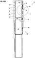
- FIGS. 10A-12 another example of the injection valve 16 is representatively illustrated.
- the valve 16 is depicted in a closed configuration.
- FIG. 11 depicts an enlarged scale view of the actuator 50.
- FIG. 12 depicts an enlarged scale view of the magnetic sensor 40.
- the support fluid 63 is contained in the chamber 64, which extends as a passage to the actuator 50.
- the chamber 66 comprises multiple annular recesses extending about the housing 30.
- a sleeve 78 isolates the chamber 66 and actuator 50 from well fluid in the annulus 20.
- FIG. 11 the manner in which the pressure barrier 48 isolates the chamber 64 from the chamber 66 can be more clearly seen.
- the piercing member 46 pierces the pressure barrier 48, allowing the support fluid 63 to flow from the chamber 64 to the chamber 66 in which the valve device 44 is located.
- the chamber 66 is at or near atmospheric pressure, and contains air or an inert gas.
- the support fluid 63 can readily flow into the chamber 66, allowing the sleeve 32 to displace downwardly, due to the pressure differential across the piston 52.
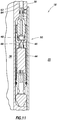
- the manner in which the magnetic sensor 40 is positioned for detecting magnetic fields and/or magnetic field changes in the passage 36 can be clearly seen.
- the magnetic sensor 40 is mounted in a plug 80 secured in the housing 30 in close proximity to the passage 36.
- the magnetic sensor 40 is preferably separated from the flow passage 36 by a pressure barrier 82 having a relatively low magnetic permeability.
- the pressure barrier 82 may be integrally formed as part of the plug 80, or the pressure barrier could be a separate element, etc.
- Suitable low magnetic permeability materials for the pressure barrier 82 can include Inconel and other high nickel and chromium content alloys, stainless steels (such as, 300 series stainless steels, duplex stainless steels, etc.). Inconel alloys have magnetic permeabilities of about 1 x 10 -6 , for example. Aluminum (magnetic permeability -1.26 x 10 -6 ), plastics, composites (e.g., with carbon fiber, etc.) and other nonmagnetic materials may also be used.
- the housing 30 can be made of a relatively low cost high magnetic permeability material (such as steel, having a magnetic permeability of about 9 x 10 -4 , for example), but magnetic fields produced by the magnetic device 38 in the passage 36 can be detected by the magnetic sensor 40 through the pressure barrier. That is, magnetic flux can readily pass through the relatively low magnetic permeability pressure barrier 82 without being significantly distorted.
- a relatively high magnetic permeability material 84 may be provided proximate the magnetic sensor 40 and/or pressure barrier 82, in order to focus the magnetic flux on the magnetic sensor.
- a permanent magnet (not shown) could also be used to bias the magnetic flux, for example, so that the magnetic flux is within a linear range of detection of the magnetic sensor 40.
- the relatively high magnetic permeability material 84 surrounding the sensor 40 can block or shield the sensor from other magnetic fields, such as, due to magnetism in the earth surrounding the wellbore 14.
- the material 84 allows only a focused window for magnetic fields to pass through, and only from a desired direction. This has the benefit of preventing other undesired magnetic fields from contributing to the sensor 40 output.
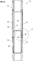
- the pressure barrier 82 is in the form of a sleeve received in the housing 30.
- the sleeve isolates the chamber 63 from fluids and pressure in the passage 36.
- the magnetic sensor 40 is disposed in an opening 86 formed through the housing 30, so that the sensor is in close proximity to the passage 36, and is separated from the passage only by the relatively low magnetic permeability pressure barrier 82.
- the sensor 40 could, for example, be mounted directly to an external surface of the pressure barrier 82.
- FIG. 14 an enlarged scale view of the magnetic sensor 40 is depicted.
- the magnetic sensor 40 is mounted to a portion 42a of the electronic circuitry 42 in the opening 86.
- one or more magnetic sensors 40 could be mounted to a small circuit board with hybrid electronics thereon.
- valve 16 the scope of this disclosure is not limited to any particular positioning or arrangement of various components in the valve 16. Indeed, the principles of this disclosure are applicable to a large variety of different configurations, and to a large variety of different types of well tools (e.g., packers, circulation valves, tester valves, perforating equipment, completion equipment, sand screens, drilling equipment, artificial lift equipment, formation stimulation equipment, formation sensors, etc.).
- well tools e.g., packers, circulation valves, tester valves, perforating equipment, completion equipment, sand screens, drilling equipment, artificial lift equipment, formation stimulation equipment, formation sensors, etc.
- the senor 40 is depicted as being included in the valve 16, it will be appreciated that the sensor could be otherwise positioned.
- the sensor 40 could be located in another housing interconnected in the tubular string 12 above or below one or more of the valves 16a-e in the system 10 of FIG. 1 .
- Multiple sensors 40 could be used, for example, to detect a pattern of magnetic field-producing components on a magnetic device 38.
- Multiple sensors 40 can be used to detect the magnetic field(s) in an axial, radial or circumferential direction. Detecting the magnetic field(s) in multiple directions can increase confidence that the magnetic device 38 will be detected regardless of orientation. Thus, it should be understood that the scope of this disclosure is not limited to any particular positioning or number of the sensor(s) 40.
- the senor 40 can detect magnetic signals which correspond to displacing one or more magnetic devices 38 in the well (e.g., through the passage 36, etc.) in certain respective patterns.
- the transmitting of different magnetic signals can be used to actuate corresponding different sets of the valves 16a-e.
- displacing a pattern of magnetic devices 38 in a well can be used to transmit a corresponding magnetic signal to well tools (such as valves 16a-e, etc.), and at least one of the well tools can actuate in response to detection of the magnetic signal.
- the pattern may comprise a predetermined number of the magnetic devices 38, a predetermined spacing in time of the magnetic devices 38, or a predetermined spacing on time between predetermined numbers of the magnetic devices 38, etc. Any pattern may be used in keeping with the scope of this disclosure.
- the magnetic device pattern can comprise a predetermined magnetic field pattern (such as, the pattern of magnetic field-producing components on the magnetic device 38 of FIGS. 7 & 8 , etc.), a predetermined pattern of multiple magnetic fields (such as, a pattern produced by displacing multiple magnetic devices 38 in a certain manner through the well, or a pattern produced by displacing a magnetic device which produces a time varying magnetic field, etc.), a predetermined change in a magnetic field (such as, a change produced by displacing a metallic device past or to the sensor 40), and/or a predetermined pattern of multiple magnetic field changes (such as, a pattern produced by displacing multiple metallic devices in a certain manner past or to the sensor 40, etc.). Any manner of producing a magnetic device pattern may be used, within the scope of this disclosure.
- a first set of the well tools might actuate in response to detection of a first magnetic signal.
- a second set of the well tools might actuate in response to detection of another magnetic signal.
- the second magnetic signal can correspond to a second unique magnetic device pattern produced in the well.
- pattern is used in this context to refer to an arrangement of magnetic field-producing components (such as permanent magnets 68, etc.) of a magnetic device 38 (as in the FIGS. 7 & 8 example), and to refer to a manner in which multiple magnetic devices can be displaced in a well.
- the sensor 40 can, in some examples, detect a pattern of magnetic field-producing components of a magnetic device 38. In other examples, the sensor 40 can detect a pattern of displacing multiple magnetic devices.
- the magnetic pattern could be a time varying signal.
- the time varying signal could arise from the movement of the magnetic device 38.
- the time varying signal could arise from the magnetic device 38 producing a time varying magnetic signal.
- the time varying signal could be a relatively static magnetic signal with a principal frequency less than 10 Hertz.
- the time varying signal could be a quasi-static magnetic signal with a principal frequency component between 1 Hertz and 400 Hertz.
- the time varying signal could be a quasi-dynamic magnetic signal with a principal frequency component between 100 Hertz and 3,000 Hertz.
- the time varying signal could be a dynamic magnetic signal with a principal frequency component greater than 3,000 Hertz.
- the sensor 40 may detect a pattern on a single magnetic device 38, such as the magnetic device of FIGS. 7 & 8 .
- magnetic field-producing components could be axially spaced on a magnetic device 38, such as a dart, rod, etc.
- the sensor 40 may detect a pattern of different North-South poles of the magnetic device 38. By detecting different patterns of different magnetic field-producing components, the electronic circuitry 42 can determine whether an actuator 50 of a particular well tool should actuate or not, should actuate open or closed, should actuate more open or more closed, etc.
- the sensor 40 may detect patterns created by displacing multiple magnetic devices 38 in the well. For example, three magnetic devices 38 could be displaced in the valve 16 (or past or to the sensor 40) within three minutes of each other, and then no magnetic devices could be displaced for the next three minutes.
- the electronic circuitry 42 can receive this pattern of indications from the sensor 40, which encodes a digital command for communicating with the well tools (e.g., "waking" the well tool actuators 50 from a low power consumption "sleep” state). Once awakened, the well tool actuators 50 can, for example, actuate in response to respective predetermined numbers, timing, and/or other patterns of magnetic devices 38 displacing in the well. This method can help prevent extraneous activities (such as, the passage of wireline tools, etc. through the valve 16) from being misidentified as an operative magnetic signal.
- the valve 16 can open in response to a predetermined number of magnetic devices 38 being displaced through the valve.
- the valves 16a-e in the system 10 of FIG. 1 can open in response to different numbers of magnetic devices 38 being displaced through the valves, different ones of the valves can be made to open at different times.
- valve 16e could open when a first magnetic device 38 is displaced through the tubular string 12.
- the valve 16d could then be opened when a second magnetic device 38 is displaced through the tubular string 12.
- the valves 16b,c could be opened when a third magnetic device 38 is displaced through the tubular string 12.
- the valve 16a could be opened when a fourth magnetic device 38 is displaced through the tubular string 12.
- Any combination of number of magnetic device(s) 38, pattern on one or more magnetic device(s), pattern of magnetic devices, spacing in time between magnetic devices, etc., can be detected by the magnetic sensor 40 and evaluated by the electronic circuitry 42 to determine whether the valve 16 should be actuated. Any unique combination of number of magnetic device(s) 38, pattern on one or more magnetic device(s), pattern of magnetic devices, spacing in time between magnetic devices, etc., may be used to select which of multiple sets of valves 16 will be actuated.
- the magnetic device 38 may be conveyed through the passage 36 by any means.
- the magnetic device 38 could be pumped, dropped, or conveyed by wireline, slickline, coiled tubing, jointed tubing, drill pipe, casing, etc.
- the magnetic device 38 is described as being displaced through the passage 36, and the magnetic sensor 40 is described as being in the valve 16 surrounding the passage, in other examples these positions could be reversed. That is, the valve 16 could include the magnetic device 38, which is used to transmit a magnetic signal to the sensor 40 in the passage 36.
- the magnetic sensor 40 could be included in a tool (such as a logging tool, etc.) positioned in the passage 36, and the magnetic signal from the device 38 in the valve 16 could be used to indicate the tool's position, to convey data, to generate electricity in the tool, to actuate the tool, or for any other purpose.
- the actuator 50 in any of its FIGS. 2-11 configurations could be in actuating multiple injection valves.
- the actuator 50 could be used to actuate multiple ones of the RAPIDFRAC (TM) Sleeve marketed by Halliburton Energy Services, Inc. of Houston, Texas USA.
- the actuator 50 could initiate metering of a hydraulic fluid in the RAPIDFRAC (TM) Sleeves in response to a particular magnetic device 38 being displaced through them, so that all of them open after a certain period of time.
- the housing 30 may be made of a relatively inexpensive ferromagnetic material, such as steel. After being machined, the housing 30 may be degaussed, but the degaussing may not remove all magnetism resulting from the machining. Even if the degaussing is completely effective, during transport and installation in a well the housing 30 can become magnetized.
- the valve 16 example of FIG. 15 includes a magnetic shield 84a.
- the magnetic shield 84a may be made of the same relatively high magnetic permeability material 84 as described above in relation to the FIG. 12 embodiment.
- Suitable relatively high magnetic permeability materials with relatively low residual magnetization include mu-metals, METGLAS(TM), NANOPERM(TM), electrical steel, permalloy, and other metals comprising nickel, iron and molybdenum. Other materials may be used, if desired.
- a nano-crystalline grain structure ferromagnetic metal coating could be applied to an interior of the plug 80 (or to an enclosure of the magnetic sensor 40) surrounding the sensor to serve as the magnetic shield 84a.
- the magnetic shield 84a could have multiple layers. For example, an outer layer could have a relatively high magnetic saturation, and an inner layer could have a relatively low remnant magnetic field.
- the magnetic shield 84a is in an annular form surrounding the sensor 40. Since magnetization of the housing 30 would typically produce a magnetic field B generally parallel to a longitudinal axis 88 of the housing, the magnetic shield 84a can be positioned so that it is on opposite longitudinal sides (relative to the longitudinal housing axis 88) of the sensor 40.
- the magnetic shield 84a is continuous from one longitudinal side 90a of the sensor 40 to the opposite longitudinal side 90b.
- the magnetic shield 84a is between the sensor side 90a and the housing 30, and is between the sensor side 90b and the housing. In this manner, the magnetic shield 84a can conduct the magnetic field B around the sensor 40.
- FIG. 16 another example of the magnetic shield 84a is representatively illustrated.
- two magnetic sensors 40 are positioned in a cavity 92 formed in the magnetic shield 84a.
- the cavity 92 is dome-shaped (substantially hemispherical) as depicted in FIG. 16 .
- An exterior of the shield 84a could also be dome-shaped, if desired, but in the FIG. 16 example the exterior is cylindrical. Of course, other shapes may be used in keeping with the principles of this disclosure.
- the shield 84a of FIG. 16 is positioned on opposite longitudinal sides of the sensors 40 (relative to the housing longitudinal axis 88), and so the shield can conduct a magnetic field B around the sensors.
- the shield 84a is between the housing 30 and the opposite longitudinal sides of the sensors 40.
- the shield 84a is in the form of an arc.
- the arc extends longitudinally from one side to the other of the sensors 40a,b.
- One end of the arc is positioned between the housing 30 and one longitudinal side of the sensors 40a,b, and an opposite end of the arc is positioned between the housing and an opposite longitudinal side of the sensors, the arc being continuous from one of its ends to the other.
- the shield 84a can conduct a magnetic field B longitudinally around the sensors 40a,b.
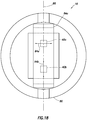
- FIG. 18 an elevational view of the magnetic sensors 40a,b and the magnetic shield 84a in the plug 80 is representatively illustrated.
- the shield 84a is aligned with the longitudinal axis 88.
- a line drawn from one end of the shield 84a to the opposite end of the shield would be parallel to the longitudinal axis 88.
- the magnetic sensors 40a,b are longitudinally enclosed by the shield 84a, in that the shield is interposed between the sensors and the housing 30 on both longitudinal sides of the sensors.
- the arc shape of the shield 84a conveniently provides for the shield to extend continuously from one of its ends to the other, different shapes (such as, rectilinear) could be used.
- the scope of this disclosure is not limited to any particular shape of the shield 84a.
- the magnetic sensors 40a,b are of a type that senses a magnetic field oriented in a particular direction. Such magnetic sensors are known to those skilled in the art as one-axis or uniaxial sensors.
- the senor 40a is arranged so that it senses a magnetic field in a lateral direction 94a orthogonal to the longitudinal axis 88
- the sensor 40b is arranged so that it senses a magnetic field in a longitudinal direction 94b parallel to the longitudinal axis 88.
- This configuration is effective for sensing changes in magnetic field caused by presence of the magnetic device 38 in the passage 36.
- magnetic sensors 40 may be used in any of the valve 16 examples described above (or in any other types of well tools).
- the magnetic shield 84a comprises a relatively high magnetic permeability and relatively low residual magnetization (low coercivity, magnetically soft) material. In this manner, the shield 84a can readily conduct all (or a substantial proportion) of an undesired magnetic field B around the sensor(s) 40, so that detection of the undesired magnetic field is mitigated and detection of magnetic field changes due to presence of the magnetic device 38 is enhanced.
- the magnetic shield 84a could comprise a diamagnetic material having a negative magnetic permeability. In this manner, the shield 84a would "repel" the undesired magnetic field B away from the sensor 40, instead of conducting the magnetic field around the sensor.
- Suitable diamagnetic materials include bismuth, pyrolytic carbon and superconductors. However, other materials could be used in keeping with the scope of this disclosure. Such diamagnetic material could be used in any of the shield 84a configurations described above, or in other configurations.
- the magnetic shield 84a could be used in any configurations of the valve 16 described above, or in any other types of well tools, to shield a magnetic sensor and mitigate detection of one or more magnetic fields B for which detection is not desired.
- the magnetic shield 84a is positioned between the housing 30 and opposite longitudinal sides 90a,b of the sensor(s) 40, in other examples the magnetic shield could be otherwise positioned.
- the magnetic shield 84a would not necessarily be positioned on opposite longitudinal sides of the sensor(s) 40.
- the magnetic shield 84a can be positioned between any opposite sides of the sensor (s) 40 oriented in a direction of the magnetic field for which detection is to be mitigated.
- the injection valve 16 can be conveniently and reliably opened by displacing the magnetic device 38 into the valve, or otherwise detecting a particular magnetic signal by a sensor 40 of the valve.
- the principles of this disclosure can be applied to a variety of well tools in which it is desired to sense changes in magnetic fields.
- the well tool can include at least one magnetic sensor 40 having first and second opposite sides 90a,b, and a magnetic shield 84a that conducts an undesired magnetic field B around, or away from, the magnetic sensor from the first opposite side 90a to the second opposite side 90b.
- the magnetic shield 84a may enclose the magnetic sensor 40 on each of the first and second opposite sides 90a,b.
- the magnetic shield 84a can be interposed between a structure (such as the housing 30) that conducts the undesired magnetic field B and each of the first and second opposite sides 90a,b.
- the magnetic shield 84a may be continuous from the first opposite side 90a of the magnetic sensor 40 to the second opposite side 90b of the magnetic sensor 40.
- the magnetic shield 40 can comprise a relatively high magnetic permeability material.
- the magnetic shield 40 can comprise a negative magnetic permeability material.
- the magnetic sensor 40 may comprise first and second magnetic sensors 40a,b, the first magnetic sensor 40a sensing a magnetic field oriented in a first direction 94a, and the second magnetic sensor 40b sensing a magnetic field oriented in a second direction 94b perpendicular to the first direction 94a.
- the magnetic sensor 40 may be positioned in a cavity 92 in the magnetic shield 84a.
- Another well tool example described above comprises a housing 30 having a longitudinal axis 88; at least one magnetic sensor 40 in the housing 30, the sensor 40 having first and second opposite longitudinal sides 90a,b relative to the housing longitudinal axis 88; and a magnetic shield 84a interposed between the housing 30 and each of the first and second opposite longitudinal sides 90a,b of the magnetic sensor 40.
- the magnetic sensor 40 can comprise first and second magnetic sensors 40a,b, the first magnetic sensor 40a sensing a magnetic field oriented in a first direction 94a orthogonal to the longitudinal axis 88, and the second magnetic sensor 40b sensing a magnetic field oriented in a second direction 94b parallel to the longitudinal axis 88.
- the magnetic sensor 40 may be longitudinally enclosed by the shield 84a.
- a well tool example which comprises a housing 30 having a longitudinal axis 88; first and second magnetic sensors 40a,b, the first and second sensors 40a,b having first and second opposite longitudinal sides 90a,b relative to the housing longitudinal axis 88, the first magnetic sensor 40a sensing a magnetic field oriented in a first direction 94a orthogonal to the longitudinal axis 88, and the second magnetic sensor 40b sensing a magnetic field oriented in a second direction 94b parallel to the longitudinal axis 88; and a magnetic shield 84a interposed between the housing 30 and each of the first and second opposite longitudinal sides 90a,b of the first and second magnetic sensors 40a,b.
Description
- This disclosure relates generally to equipment utilized and operations performed in conjunction with a subterranean well and, in an example described below, more particularly provides for magnetic sensing in well tools.
- It can be beneficial in some circumstances to individually, or at least selectively, actuate one or more well tools in a well. However, it can be difficult to reliably transmit and receive magnetic signals in a wellbore environment.
- Therefore, it will be appreciated that improvements are continually needed in the art. These improvements could be useful in, for example, controlling, communicating with, or actuating various types of well tools, etc.
-
US 2008/265892 A1 discloses an externally guided and directed field induction resistivity tool. -
US 2013/264051 A1 discloses well tools selectively responsive to magnetic patterns. -
US 4,901,069 A discloses an apparatus for electromagnetically coupling power and data signals between a first unit and a second unit and in particular between well bore apparatus and the surface. -
US 5,138,263 A discloses an electromagnetic formation evaluation tool. -
US 5 130 655 A discloses multiple-coil magnetic field sensor with series-connected main coils and parallel-connected feedback coils. -
US 2013/314092 A1 discloses sensing the magnetic field of the earth. - In a first aspect of the present invention, there is provided a well tool according to Claim 1.
- In a second aspect of the present invention, there is provided a well tool according to Claim 6.
- In a third aspect of the present invention, there is provided a well tool according to
Claim 11. -
-
FIG. 1 is a representative partially cross-sectional view of a well system and associated method which can embody principles of this disclosure. -
FIG. 2 is a representative cross-sectional view of an injection valve which may be used in the well system and method, and which can embody the principles of this disclosure. -
FIGS. 3-6 are a representative cross-sectional views of another example of the injection valve, in run-in, actuated and reverse flow configurations thereof. -
FIGS. 7 & 8 are representative side and plan views of a magnetic device which may be used with the injection valve. -
FIG. 9 is a representative cross-sectional view of another example of the injection valve. -
FIGS. 10A & B are representative cross-sectional views of successive axial sections of another example of the injection valve, in a closed configuration. -
FIG. 11 is an enlarged scale representative cross-sectional view of a valve device which may be used in the injection valve. -
FIG. 12 is an enlarged scale representative cross-sectional view of a magnetic sensor which may be used in the injection valve. -
FIG. 13 is a representative cross-sectional view of another example of the injection valve. -
FIG. 14 is an enlarged scale representative cross-sectional view of another example of the magnetic sensor in the injection valve ofFIG. 13 . -
FIG. 15 is an enlarged scale representative cross-sectional view of an example of magnetic shielding in the injection valve ofFIG. 12 . -
FIG. 16 is an enlarged scale representative cross-sectional view of another example of magnetic shielding in the injection valve ofFIG. 12 . -
FIG. 17 is an enlarged scale representative cross-sectional view of yet another example of magnetic shielding in the injection valve ofFIG. 12 . -
FIG. 18 is a representative elevational view of the magnetic shielding ofFIG. 17 , as viewed from position 18-18 ofFIG. 17 . - Representatively illustrated in
FIG. 1 is asystem 10 for use with a well, and an associated method, which can embody principles of this disclosure. In this example, atubular string 12 is positioned in awellbore 14, with the tubular string havingmultiple injection valves 16a-e andpackers 18a-e interconnected therein. - The
tubular string 12 may be of the type known to those skilled in the art as casing, liner, tubing, a production string, a work string, a drill string, etc. Any type of tubular string may be used and remain within the scope of this disclosure. - The
packers 18a-e seal off anannulus 20 formed radially between thetubular string 12 and thewellbore 14. Thepackers 18a-e in this example are designed for sealing engagement with an uncased oropen hole wellbore 14, but if the wellbore is cased or lined, then cased hole-type packers may be used instead. Swellable, inflatable, expandable and other types of packers may be used, as appropriate for the well conditions, or no packers may be used (for example, thetubular string 12 could be expanded into contact with thewellbore 14, the tubular string could be cemented in the wellbore, etc.). - In the
FIG. 1 example, theinjection valves 16a-e permit selective fluid communication between an interior of thetubular string 12 and each section of theannulus 20 isolated between two of thepackers 18a-e. Each section of theannulus 20 is in fluid communication with a correspondingearth formation zone 22a-d. Of course, ifpackers 18a-e are not used, then theinjection valves 16a-e can otherwise be placed in communication with theindividual zones 22a-d, for example, with perforations, etc. - The
zones 22a-d may be sections of asame formation 22, or they may be sections of different formations. Eachzone 22a-d may be associated with one or more of theinjection valves 16a-e. - In the
FIG. 1 example, twoinjection valves 16b,c are associated with the section of theannulus 20 isolated between thepackers 18b,c, and this section of the annulus is in communication with theassociated zone 22b. It will be appreciated that any number of injection valves may be associated with a zone. - It is sometimes beneficial to initiate
fractures 26 at multiple locations in a zone (for example, in tight shale formations, etc.), in which cases the multiple injection valves can provide for injectingfluid 24 at multiple fracture initiation points along thewellbore 14. In the example depicted inFIG. 1 , thevalve 16c has been opened, andfluid 24 is being injected into thezone 22b, thereby forming thefractures 26. - Preferably, the
other valves 16a,b,d,e are closed while thefluid 24 is being flowed out of thevalve 16c and into thezone 22b. This enables all of thefluid 24 flow to be directed toward forming thefractures 26, with enhanced control over the operation at that particular location. - However, in other examples,
multiple valves 16a-e could be open while thefluid 24 is flowed into a zone of anearth formation 22. In thewell system 10, for example, both of thevalves 16b,c could be open while thefluid 24 is flowed into thezone 22b. This would enable fractures to be formed at multiple fracture initiation locations corresponding to the open valves. - It will, thus, be appreciated that it would be beneficial to be able to open different sets of one or more of the
valves 16a-e at different times. For example, one set (such asvalves 16b,c) could be opened at one time (such as, when it is desired to formfractures 26 into thezone 22b), and another set (such asvalve 16a) could be opened at another time (such as, when it is desired to form fractures into thezone 22a). - One or more sets of the
valves 16a-e could be open simultaneously. However, it is generally preferable for only one set of thevalves 16a-e to be open at a time, so that thefluid 24 flow can be concentrated on a particular zone, and so flow into that zone can be individually controlled. - At this point, it should be noted that the
well system 10 and method is described here and depicted in the drawings as merely one example of a wide variety of possible systems and methods which can incorporate the principles of this disclosure. Therefore, it should be understood that those principles are not limited in any manner to the details of thesystem 10 or associated method, or to the details of any of the components thereof (for example, thetubular string 12, thewellbore 14, thevalves 16a-e, thepackers 18a-e, etc.). - It is not necessary for the
wellbore 14 to be vertical as depicted inFIG. 1 , for the wellbore to be uncased, for there to be five each of thevalves 16a-e and packers, for there to be four of thezones 22a-d, forfractures 26 to be formed in the zones, for thefluid 24 to be injected, etc. Thefluid 24 could be any type of fluid which is injected into an earth formation, e.g., for stimulation, conformance, acidizing, fracturing, water-flooding, steam-flooding, treatment, gravel packing, cementing, or any other purpose. Thus, it will be appreciated that the principles of this disclosure are applicable to many different types of well systems and operations. - In other examples, the principles of this disclosure could be applied in circumstances where fluid is not only injected, but is also (or only) produced from the
formation 22. In these examples, the fluid 24 could be oil, gas, water, etc., produced from theformation 22. Thus, well tools other than injection valves can benefit from the principles described herein. - Referring additionally now to
FIG. 2 , an enlarged scale cross-sectional view of one example of theinjection valve 16 is representatively illustrated. Theinjection valve 16 ofFIG. 2 may be used in thewell system 10 and method ofFIG. 1 , or it may be used in other well systems and methods, while still remaining within the scope of this disclosure. - In the
FIG. 2 example, thevalve 16 includesopenings 28 in a sidewall of a generallytubular housing 30. Theopenings 28 are blocked by asleeve 32, which is retained in position byshear members 34. - In this configuration, fluid communication is prevented between the
annulus 20 external to thevalve 16, and aninternal flow passage 36 which extends longitudinally through the valve (and which extends longitudinally through thetubular string 12 when the valve is interconnected therein). Thevalve 16 can be opened, however, by shearing theshear members 34 and displacing the sleeve 32 (downward as viewed inFIG. 2 ) to a position in which the sleeve does not block theopenings 28. - To open the
valve 16, amagnetic device 38 is displaced into the valve to activate anactuator 50 thereof. Themagnetic device 38 is depicted inFIG. 2 as being generally cylindrical, but other shapes and types of magnetic devices (such as, balls, darts, plugs, wipers, fluids, gels, etc.) may be used in other examples. For example, a ferrofluid, magnetorheological fluid, or any other fluid having magnetic properties which can be sensed by thesensor 40, could be pumped to or past the sensor in order to transmit a magnetic signal to theactuator 50. - The
magnetic device 38 may be displaced into thevalve 16 by any technique. For example, themagnetic device 38 can be dropped through thetubular string 12, pumped by flowing fluid through thepassage 36, self-propelled, conveyed by wireline, slickline, coiled tubing, jointed tubing, etc. - The
magnetic device 38 has known magnetic properties, and/or produces a known magnetic field, or pattern or combination of magnetic fields, which is/are detected by amagnetic sensor 40 of thevalve 16. Themagnetic sensor 40 can be any type of sensor which is capable of detecting the presence of the magnetic field(s) produced by themagnetic device 38, and/or one or more other magnetic properties of the magnetic device. - Suitable sensors include (but are not limited to) giant magneto-resistive (GMR) sensors, Hall-effect sensors, conductive coils, a super conductive quantum interference device (SQUID), etc. Permanent magnets can be combined with the
magnetic sensor 40 in order to create a magnetic field that is disturbed by themagnetic device 38. A change in the magnetic field can be detected by thesensor 40 as an indication of the presence of themagnetic device 38. - The
sensor 40 is connected toelectronic circuitry 42 which determines whether the sensor has detected a particular predetermined magnetic field, or pattern or combination of magnetic fields, magnetic permittivity or other magnetic properties of themagnetic device 38. For example, theelectronic circuitry 42 could have the predetermined magnetic field(s), magnetic permittivity or other magnetic properties programmed into non-volatile memory for comparison to magnetic fields/properties detected by thesensor 40. Theelectronic circuitry 42 could be supplied with electrical power via an on-board battery, a downhole generator, or any other electrical power source. - In one example, the
electronic circuitry 42 could include a capacitor, wherein an electrical resonance behavior between the capacitance of the capacitor and themagnetic sensor 40 changes, depending on whether themagnetic device 38 is present. In another example, theelectronic circuitry 42 could include an adaptive magnetic field that adjusts to a baseline magnetic field of the surrounding environment (e.g., theformation 22, surrounding metallic structures, etc.). Theelectronic circuitry 42 could determine whether the measured magnetic fields exceed the adaptive magnetic field level. - In one example, the
sensor 40 could comprise an inductive sensor which can detect the presence of a metallic device (e.g., by detecting a change in a magnetic field, etc.). The metallic device (such as a metal ball or dart, etc.) can be considered amagnetic device 38, in the sense that it conducts a magnetic field and produces changes in a magnetic field which can be detected by thesensor 40. - If the
electronic circuitry 42 determines that thesensor 40 has detected the predetermined magnetic field(s) or change(s) in magnetic field(s), the electronic circuitry causes avalve device 44 to open. In this example, thevalve device 44 includes a piercingmember 46 which pierces apressure barrier 48. - The piercing
member 46 can be driven by any means, such as, by an electrical, hydraulic, mechanical, explosive, chemical or other type of actuator. Other types of valve devices 44 (such as those described inUS patent application no. 12/688058 and inU.S. patent no. 8235103 ) may be used, in keeping with the scope of this disclosure. - When the
valve device 44 is opened, apiston 52 on amandrel 54 becomes unbalanced (e.g., a pressure differential is created across the piston), and the piston displaces downward as viewed inFIG. 2 . This displacement of thepiston 52 could, in some examples, be used to shear theshear members 34 and displace thesleeve 32 to its open position. - However, in the
FIG. 2 example, thepiston 52 displacement is used to activate aretractable seat 56 to a sealing position thereof. As depicted inFIG. 2 , theretractable seat 56 is in the form ofresilient collets 58 which are initially received in anannular recess 60 formed in thehousing 30. In this position, theretractable seat 56 is retracted, and is not capable of sealingly engaging themagnetic device 38 or any other form of plug in theflow passage 36. - A time delay could be provided between the
sensor 40 detecting the predetermined magnetic field or change in magnetic filed, and the piercingmember 46 opening thevalve device 44. Such a time delay could be programmed in theelectronic circuitry 42. - When the
piston 52 displaces downward, thecollets 58 are deflected radially inward by aninclined face 62 of therecess 60, and theseat 56 is then in its sealing position. A plug (such as, a ball, a dart, amagnetic device 38, etc.) can sealingly engage theseat 56, and increased pressure can be applied to thepassage 36 above the plug to thereby shear theshear members 34 and downwardly displace thesleeve 32 to its open position. - As mentioned above, the
retractable seat 56 may be sealingly engaged by themagnetic device 38 which initially activates the actuator 50 (e.g., in response to thesensor 40 detecting the predetermined magnetic field(s) or change(s) in magnetic field(s) produced by the magnetic device), or the retractable seat may be sealingly engaged by another magnetic device and/or plug subsequently displaced into thevalve 16. - Furthermore, the
retractable seat 56 may be actuated to its sealing position in response to displacement of more than onemagnetic device 38 into thevalve 16. For example, theelectronic circuitry 42 may not actuate thevalve device 44 until a predetermined number of themagnetic devices 38 have been displaced into thevalve 16, and/or until a predetermined spacing in time is detected, etc. - Referring additionally now to
FIGS. 3-6 , another example of theinjection valve 16 is representatively illustrated. In this example, thesleeve 32 is initially in a closed position, as depicted inFIG. 3 . Thesleeve 32 is displaced to its open position (seeFIG. 4 ) when asupport fluid 63 is flowed from onechamber 64 to anotherchamber 66. - The
chambers pressure barrier 48. When thesensor 40 detects the predetermined magnetic signal(s) produced by the magnetic device(s) 38, the piercingmember 46 pierces thepressure barrier 48, and thesupport fluid 63 flows from thechamber 64 to thechamber 66, thereby allowing a pressure differential across thesleeve 32 to displace the sleeve downward to its open position, as depicted inFIG. 4 . -
Fluid 24 can now be flowed outward through theopenings 28 from thepassage 36 to theannulus 20. Note that theretractable seat 56 is now extended inwardly to its sealing position. In this example, theretractable seat 56 is in the form of an expandable ring which is extended radially inward to its sealing position by the downward displacement of thesleeve 32. - In addition, note that the
magnetic device 38 in this example comprises a ball or sphere. Preferably, one or morepermanent magnets 68 or other type of magnetic field-producing components are included in themagnetic device 38. - In
FIG. 5 , themagnetic device 38 is retrieved from thepassage 36 by reverse flow of fluid through the passage 36 (e.g., upward flow as viewed inFIG. 5 ). Themagnetic device 38 is conveyed upwardly through thepassage 36 by this reverse flow, and eventually engages in sealing contact with theseat 56, as depicted inFIG. 5 . - In
FIG. 6 , a pressure differential across themagnetic device 38 andseat 56 causes them to be displaced upward against a downward biasing force exerted by aspring 70 on aretainer sleeve 72. When the biasing force is overcome, themagnetic device 38,seat 56 andsleeve 72 are displaced upward, thereby allowing theseat 56 to expand outward to its retracted position, and allowing themagnetic device 38 to be conveyed upward through thepassage 36, e.g., for retrieval to the surface. - Note that in the
FIGS. 2 & 3-6 examples, theseat 58 is initially expanded or "retracted" from its sealing position, and is later deflected inward to its sealing position. In theFIGS. 3-6 example, theseat 58 can then be again expanded (seeFIG. 6 ) for retrieval of the magnetic device 38 (or to otherwise minimize obstruction of the passage 36). - The
seat 58 in both of these examples can be considered "retractable," in that the seat can be in its inward sealing position, or in its outward non-sealing position, when desired. Thus, theseat 58 can be in its non-sealing position when initially installed, and then can be actuated to its sealing position (e.g., in response to detection of a predetermined pattern or combination of magnetic fields), without later being actuated to its sealing position again, and still be considered a "retractable" seat. - Referring additionally now to
FIGS. 7 & 8 , another example of themagnetic device 38 is representatively illustrated. In this example, magnets (not shown inFIGS. 7 & 8 , see, e.g.,permanent magnet 68 inFIG. 4 ) are retained inrecesses 74 formed in an outer surface of asphere 76. - The
recesses 74 are arranged in a pattern which, in this case, resembles that of stitching on a baseball. InFIGS. 7 & 8 , the pattern comprises spaced apart positions distributed along a continuous undulating path about thesphere 76. - However, it should be clearly understood that any pattern of magnetic field-producing components may be used in the
magnetic device 38, in keeping with the scope of this disclosure. For example, the magnetic field-producing components could be arranged in lines from one side of thesphere 76 to an opposite side. - The
magnets 68 are preferably arranged to provide a magnetic field a substantial distance from thedevice 38, and to do so no matter the orientation of thesphere 76. The pattern depicted inFIGS. 7 & 8 desirably projects the produced magnetic field(s) substantially evenly around thesphere 76. - In some examples, the pattern can desirably project the produced magnetic field(s) in at least one axis around the
sphere 76. In these examples, the magnetic field(s) may not be even, but can point in different directions. Preferably, the magnetic field(s) are detectable all around thesphere 76. - The magnetic field(s) may be produced by permanent magnets, electromagnets, a combination, etc. Any type of magnetic field producing components may be used in the
magnetic device 38. The magnetic field(s) produced by themagnetic device 38 may vary, for example, to transmit data, information, commands, etc., or to generate electrical power (e.g., in a coil through which the magnetic field passes). - Referring additionally now to
FIG. 9 , another example of theinjection valve 16 is representatively illustrated. In this example, theactuator 50 includes two of thevalve devices 44. - When one of the
valve devices 44 opens, a sufficient amount of thesupport fluid 63 is drained to displace thesleeve 32 to its open position (similar to, e.g.,FIG. 4 ), in which the fluid 24 can be flowed outward through theopenings 28. When theother valve device 44 opens, more of thesupport fluid 63 is drained, thereby further displacing thesleeve 32 to a closed position (as depicted inFIG. 9 ), in which flow through theopenings 28 is prevented by the sleeve. - Various different techniques may be used to control actuation of the
valve devices 44. For example, one of thevalve devices 44 may be opened when a firstmagnetic device 38 is displaced into thevalve 16, and the other valve device may be opened when a second magnetic device is displaced into the valve. As another example, thesecond valve device 44 may be actuated in response to passage of a predetermined amount of time from a particularmagnetic device 38, or a predetermined number of magnetic devices, being detected by thesensor 40. - As yet another example, the
first valve device 44 may actuate when a certain number ofmagnetic devices 38 have been displaced into thevalve 16, and thesecond valve device 44 may actuate when another number of magnetic devices have been displaced into the valve. In other examples, thefirst valve device 44 could actuate when an appropriate magnetic signal is detected by thesensor 40, and the second magnetic device could actuate when another sensor senses another condition (such as, a change in temperature, pressure, etc.). Thus, it should be understood that any technique for controlling actuation of thevalve devices 44 may be used, in keeping with the scope of this disclosure. - Referring additionally now to
FIGS. 10A-12 , another example of theinjection valve 16 is representatively illustrated. InFIGS. 10A & B , thevalve 16 is depicted in a closed configuration.FIG. 11 depicts an enlarged scale view of theactuator 50.FIG. 12 depicts an enlarged scale view of themagnetic sensor 40. - In
FIGS. 10A & B , it may be seen that thesupport fluid 63 is contained in thechamber 64, which extends as a passage to theactuator 50. In addition, thechamber 66 comprises multiple annular recesses extending about thehousing 30. Asleeve 78 isolates thechamber 66 andactuator 50 from well fluid in theannulus 20. - In
FIG. 11 , the manner in which thepressure barrier 48 isolates thechamber 64 from thechamber 66 can be more clearly seen. When thevalve device 44 is actuated, the piercingmember 46 pierces thepressure barrier 48, allowing thesupport fluid 63 to flow from thechamber 64 to thechamber 66 in which thevalve device 44 is located. - Initially, the
chamber 66 is at or near atmospheric pressure, and contains air or an inert gas. Thus, thesupport fluid 63 can readily flow into thechamber 66, allowing thesleeve 32 to displace downwardly, due to the pressure differential across thepiston 52. - In
FIG. 12 , the manner in which themagnetic sensor 40 is positioned for detecting magnetic fields and/or magnetic field changes in thepassage 36 can be clearly seen. In this example, themagnetic sensor 40 is mounted in aplug 80 secured in thehousing 30 in close proximity to thepassage 36. - The
magnetic sensor 40 is preferably separated from theflow passage 36 by apressure barrier 82 having a relatively low magnetic permeability. Thepressure barrier 82 may be integrally formed as part of theplug 80, or the pressure barrier could be a separate element, etc. - Suitable low magnetic permeability materials for the
pressure barrier 82 can include Inconel and other high nickel and chromium content alloys, stainless steels (such as, 300 series stainless steels, duplex stainless steels, etc.). Inconel alloys have magnetic permeabilities of about 1 x 10⁻⁶, for example. Aluminum (magnetic permeability -1.26 x 10⁻⁶), plastics, composites (e.g., with carbon fiber, etc.) and other nonmagnetic materials may also be used. - One advantage of making the
pressure barrier 82 out of a low magnetic permeability material is that thehousing 30 can be made of a relatively low cost high magnetic permeability material (such as steel, having a magnetic permeability of about 9 x 10⁻⁴, for example), but magnetic fields produced by themagnetic device 38 in thepassage 36 can be detected by themagnetic sensor 40 through the pressure barrier. That is, magnetic flux can readily pass through the relatively low magneticpermeability pressure barrier 82 without being significantly distorted. - In some examples, a relatively high
magnetic permeability material 84 may be provided proximate themagnetic sensor 40 and/orpressure barrier 82, in order to focus the magnetic flux on the magnetic sensor. A permanent magnet (not shown) could also be used to bias the magnetic flux, for example, so that the magnetic flux is within a linear range of detection of themagnetic sensor 40. - In some examples, the relatively high
magnetic permeability material 84 surrounding thesensor 40 can block or shield the sensor from other magnetic fields, such as, due to magnetism in the earth surrounding thewellbore 14. Thematerial 84 allows only a focused window for magnetic fields to pass through, and only from a desired direction. This has the benefit of preventing other undesired magnetic fields from contributing to thesensor 40 output. - Referring additionally now to
FIGS. 13 &14 , another example of thevalve 16 is representatively illustrated. In this example, thepressure barrier 82 is in the form of a sleeve received in thehousing 30. The sleeve isolates thechamber 63 from fluids and pressure in thepassage 36. - In this example, the
magnetic sensor 40 is disposed in anopening 86 formed through thehousing 30, so that the sensor is in close proximity to thepassage 36, and is separated from the passage only by the relatively low magneticpermeability pressure barrier 82. Thesensor 40 could, for example, be mounted directly to an external surface of thepressure barrier 82. - In
FIG. 14 , an enlarged scale view of themagnetic sensor 40 is depicted. In this example, themagnetic sensor 40 is mounted to aportion 42a of theelectronic circuitry 42 in theopening 86. For example, one or moremagnetic sensors 40 could be mounted to a small circuit board with hybrid electronics thereon. - Thus, it should be understood that the scope of this disclosure is not limited to any particular positioning or arrangement of various components in the
valve 16. Indeed, the principles of this disclosure are applicable to a large variety of different configurations, and to a large variety of different types of well tools (e.g., packers, circulation valves, tester valves, perforating equipment, completion equipment, sand screens, drilling equipment, artificial lift equipment, formation stimulation equipment, formation sensors, etc.). - Although in the examples of
FIGS. 2-14 , thesensor 40 is depicted as being included in thevalve 16, it will be appreciated that the sensor could be otherwise positioned. For example, thesensor 40 could be located in another housing interconnected in thetubular string 12 above or below one or more of thevalves 16a-e in thesystem 10 ofFIG. 1 . -
Multiple sensors 40 could be used, for example, to detect a pattern of magnetic field-producing components on amagnetic device 38.Multiple sensors 40 can be used to detect the magnetic field(s) in an axial, radial or circumferential direction. Detecting the magnetic field(s) in multiple directions can increase confidence that themagnetic device 38 will be detected regardless of orientation. Thus, it should be understood that the scope of this disclosure is not limited to any particular positioning or number of the sensor(s) 40. - In examples described above, the
sensor 40 can detect magnetic signals which correspond to displacing one or moremagnetic devices 38 in the well (e.g., through thepassage 36, etc.) in certain respective patterns. The transmitting of different magnetic signals (corresponding to respective different patterns of displacing the magnetic devices 38) can be used to actuate corresponding different sets of thevalves 16a-e. - Thus, displacing a pattern of
magnetic devices 38 in a well can be used to transmit a corresponding magnetic signal to well tools (such asvalves 16a-e, etc.), and at least one of the well tools can actuate in response to detection of the magnetic signal. The pattern may comprise a predetermined number of themagnetic devices 38, a predetermined spacing in time of themagnetic devices 38, or a predetermined spacing on time between predetermined numbers of themagnetic devices 38, etc. Any pattern may be used in keeping with the scope of this disclosure. - The magnetic device pattern can comprise a predetermined magnetic field pattern (such as, the pattern of magnetic field-producing components on the
magnetic device 38 ofFIGS. 7 & 8 , etc.), a predetermined pattern of multiple magnetic fields (such as, a pattern produced by displacing multiplemagnetic devices 38 in a certain manner through the well, or a pattern produced by displacing a magnetic device which produces a time varying magnetic field, etc.), a predetermined change in a magnetic field (such as, a change produced by displacing a metallic device past or to the sensor 40), and/or a predetermined pattern of multiple magnetic field changes (such as, a pattern produced by displacing multiple metallic devices in a certain manner past or to thesensor 40, etc.). Any manner of producing a magnetic device pattern may be used, within the scope of this disclosure. - A first set of the well tools might actuate in response to detection of a first magnetic signal. A second set of the well tools might actuate in response to detection of another magnetic signal. The second magnetic signal can correspond to a second unique magnetic device pattern produced in the well.
- The term "pattern" is used in this context to refer to an arrangement of magnetic field-producing components (such as
permanent magnets 68, etc.) of a magnetic device 38 (as in theFIGS. 7 & 8 example), and to refer to a manner in which multiple magnetic devices can be displaced in a well. Thesensor 40 can, in some examples, detect a pattern of magnetic field-producing components of amagnetic device 38. In other examples, thesensor 40 can detect a pattern of displacing multiple magnetic devices. - The magnetic pattern could be a time varying signal. The time varying signal could arise from the movement of the
magnetic device 38. Alternatively, the time varying signal could arise from themagnetic device 38 producing a time varying magnetic signal. In some cases, the time varying signal could be a relatively static magnetic signal with a principal frequency less than 10 Hertz. In some cases, the time varying signal could be a quasi-static magnetic signal with a principal frequency component between 1 Hertz and 400 Hertz. In some cases, the time varying signal could be a quasi-dynamic magnetic signal with a principal frequency component between 100 Hertz and 3,000 Hertz. In other cases, the time varying signal could be a dynamic magnetic signal with a principal frequency component greater than 3,000 Hertz. - The
sensor 40 may detect a pattern on a singlemagnetic device 38, such as the magnetic device ofFIGS. 7 & 8 . In another example, magnetic field-producing components could be axially spaced on amagnetic device 38, such as a dart, rod, etc. In some examples, thesensor 40 may detect a pattern of different North-South poles of themagnetic device 38. By detecting different patterns of different magnetic field-producing components, theelectronic circuitry 42 can determine whether anactuator 50 of a particular well tool should actuate or not, should actuate open or closed, should actuate more open or more closed, etc. - The
sensor 40 may detect patterns created by displacing multiplemagnetic devices 38 in the well. For example, threemagnetic devices 38 could be displaced in the valve 16 (or past or to the sensor 40) within three minutes of each other, and then no magnetic devices could be displaced for the next three minutes. - The
electronic circuitry 42 can receive this pattern of indications from thesensor 40, which encodes a digital command for communicating with the well tools (e.g., "waking" thewell tool actuators 50 from a low power consumption "sleep" state). Once awakened, thewell tool actuators 50 can, for example, actuate in response to respective predetermined numbers, timing, and/or other patterns ofmagnetic devices 38 displacing in the well. This method can help prevent extraneous activities (such as, the passage of wireline tools, etc. through the valve 16) from being misidentified as an operative magnetic signal. - In one example, the
valve 16 can open in response to a predetermined number ofmagnetic devices 38 being displaced through the valve. By setting up thevalves 16a-e in thesystem 10 ofFIG. 1 to open in response to different numbers ofmagnetic devices 38 being displaced through the valves, different ones of the valves can be made to open at different times. - For example, the
valve 16e could open when a firstmagnetic device 38 is displaced through thetubular string 12. Thevalve 16d could then be opened when a secondmagnetic device 38 is displaced through thetubular string 12. Thevalves 16b,c could be opened when a thirdmagnetic device 38 is displaced through thetubular string 12. Thevalve 16a could be opened when a fourthmagnetic device 38 is displaced through thetubular string 12. - Any combination of number of magnetic device(s) 38, pattern on one or more magnetic device(s), pattern of magnetic devices, spacing in time between magnetic devices, etc., can be detected by the
magnetic sensor 40 and evaluated by theelectronic circuitry 42 to determine whether thevalve 16 should be actuated. Any unique combination of number of magnetic device(s) 38, pattern on one or more magnetic device(s), pattern of magnetic devices, spacing in time between magnetic devices, etc., may be used to select which of multiple sets ofvalves 16 will be actuated. - The
magnetic device 38 may be conveyed through thepassage 36 by any means. For example, themagnetic device 38 could be pumped, dropped, or conveyed by wireline, slickline, coiled tubing, jointed tubing, drill pipe, casing, etc. - Although in the above examples, the
magnetic device 38 is described as being displaced through thepassage 36, and themagnetic sensor 40 is described as being in thevalve 16 surrounding the passage, in other examples these positions could be reversed. That is, thevalve 16 could include themagnetic device 38, which is used to transmit a magnetic signal to thesensor 40 in thepassage 36. For example, themagnetic sensor 40 could be included in a tool (such as a logging tool, etc.) positioned in thepassage 36, and the magnetic signal from thedevice 38 in thevalve 16 could be used to indicate the tool's position, to convey data, to generate electricity in the tool, to actuate the tool, or for any other purpose. - Another use for the actuator 50 (in any of its
FIGS. 2-11 configurations) could be in actuating multiple injection valves. For example, theactuator 50 could be used to actuate multiple ones of the RAPIDFRAC (TM) Sleeve marketed by Halliburton Energy Services, Inc. of Houston, Texas USA. Theactuator 50 could initiate metering of a hydraulic fluid in the RAPIDFRAC (TM) Sleeves in response to a particularmagnetic device 38 being displaced through them, so that all of them open after a certain period of time. - In some situations, there can be magnetic fields present in the valve 16 (or other types of well tools) not produced by the
magnetic device 38. For example, in thevalve 16 ofFIGS. 10A-12 , thehousing 30 may be made of a relatively inexpensive ferromagnetic material, such as steel. After being machined, thehousing 30 may be degaussed, but the degaussing may not remove all magnetism resulting from the machining. Even if the degaussing is completely effective, during transport and installation in a well thehousing 30 can become magnetized. - To prevent remnant, residual or other spurious magnetic fields from interfering with detection of the
magnetic device 38 by themagnetic sensor 40, thevalve 16 example ofFIG. 15 includes amagnetic shield 84a. Themagnetic shield 84a may be made of the same relatively highmagnetic permeability material 84 as described above in relation to theFIG. 12 embodiment. - Suitable relatively high magnetic permeability materials with relatively low residual magnetization (low coercivity or magnetically soft) include mu-metals, METGLAS(TM), NANOPERM(TM), electrical steel, permalloy, and other metals comprising nickel, iron and molybdenum. Other materials may be used, if desired. For example, a nano-crystalline grain structure ferromagnetic metal coating could be applied to an interior of the plug 80 (or to an enclosure of the magnetic sensor 40) surrounding the sensor to serve as the
magnetic shield 84a. - In some examples, the
magnetic shield 84a could have multiple layers. For example, an outer layer could have a relatively high magnetic saturation, and an inner layer could have a relatively low remnant magnetic field. - In the
FIG. 15 example, themagnetic shield 84a is in an annular form surrounding thesensor 40. Since magnetization of thehousing 30 would typically produce a magnetic field B generally parallel to alongitudinal axis 88 of the housing, themagnetic shield 84a can be positioned so that it is on opposite longitudinal sides (relative to the longitudinal housing axis 88) of thesensor 40. - The
magnetic shield 84a is continuous from onelongitudinal side 90a of thesensor 40 to the oppositelongitudinal side 90b. Themagnetic shield 84a is between thesensor side 90a and thehousing 30, and is between thesensor side 90b and the housing. In this manner, themagnetic shield 84a can conduct the magnetic field B around thesensor 40. - Referring additionally now to
FIG. 16 , another example of themagnetic shield 84a is representatively illustrated. In this example, twomagnetic sensors 40 are positioned in acavity 92 formed in themagnetic shield 84a. - The
cavity 92 is dome-shaped (substantially hemispherical) as depicted inFIG. 16 . An exterior of theshield 84a could also be dome-shaped, if desired, but in theFIG. 16 example the exterior is cylindrical. Of course, other shapes may be used in keeping with the principles of this disclosure. - The
shield 84a ofFIG. 16 is positioned on opposite longitudinal sides of the sensors 40 (relative to the housing longitudinal axis 88), and so the shield can conduct a magnetic field B around the sensors. In theFIG. 16 example, theshield 84a is between thehousing 30 and the opposite longitudinal sides of thesensors 40. - Referring additionally now to
FIG. 17 , another example of themagnetic shield 84a is representatively illustrated. In this example, theshield 84a is in the form of an arc. - The arc extends longitudinally from one side to the other of the
sensors 40a,b. One end of the arc is positioned between thehousing 30 and one longitudinal side of thesensors 40a,b, and an opposite end of the arc is positioned between the housing and an opposite longitudinal side of the sensors, the arc being continuous from one of its ends to the other. In this manner, theshield 84a can conduct a magnetic field B longitudinally around thesensors 40a,b. - Referring additionally now to
FIG. 18 , an elevational view of themagnetic sensors 40a,b and themagnetic shield 84a in theplug 80 is representatively illustrated. In this view, it can be clearly seen that theshield 84a is aligned with thelongitudinal axis 88. For example, a line drawn from one end of theshield 84a to the opposite end of the shield would be parallel to thelongitudinal axis 88. - The
magnetic sensors 40a,b are longitudinally enclosed by theshield 84a, in that the shield is interposed between the sensors and thehousing 30 on both longitudinal sides of the sensors. Although the arc shape of theshield 84a conveniently provides for the shield to extend continuously from one of its ends to the other, different shapes (such as, rectilinear) could be used. The scope of this disclosure is not limited to any particular shape of theshield 84a. - In the
FIG. 18 example, themagnetic sensors 40a,b are of a type that senses a magnetic field oriented in a particular direction. Such magnetic sensors are known to those skilled in the art as one-axis or uniaxial sensors. - As depicted in
FIG. 18 , thesensor 40a is arranged so that it senses a magnetic field in alateral direction 94a orthogonal to thelongitudinal axis 88, and thesensor 40b is arranged so that it senses a magnetic field in alongitudinal direction 94b parallel to thelongitudinal axis 88. This configuration is effective for sensing changes in magnetic field caused by presence of themagnetic device 38 in thepassage 36. - However, other types, numbers and configurations of magnetic sensors can be used in keeping with the scope of this disclosure.
Multiple sensors 40, and multiaxial or uniaxial sensors, may be used in any of thevalve 16 examples described above (or in any other types of well tools). - In the above description of the
FIGS. 15-18 examples, themagnetic shield 84a comprises a relatively high magnetic permeability and relatively low residual magnetization (low coercivity, magnetically soft) material. In this manner, theshield 84a can readily conduct all (or a substantial proportion) of an undesired magnetic field B around the sensor(s) 40, so that detection of the undesired magnetic field is mitigated and detection of magnetic field changes due to presence of themagnetic device 38 is enhanced. - In other examples, the
magnetic shield 84a could comprise a diamagnetic material having a negative magnetic permeability. In this manner, theshield 84a would "repel" the undesired magnetic field B away from thesensor 40, instead of conducting the magnetic field around the sensor. - Suitable diamagnetic materials include bismuth, pyrolytic carbon and superconductors. However, other materials could be used in keeping with the scope of this disclosure. Such diamagnetic material could be used in any of the
shield 84a configurations described above, or in other configurations. - The
magnetic shield 84a could be used in any configurations of thevalve 16 described above, or in any other types of well tools, to shield a magnetic sensor and mitigate detection of one or more magnetic fields B for which detection is not desired. - Although, in examples described above, the
magnetic shield 84a is positioned between thehousing 30 and oppositelongitudinal sides 90a,b of the sensor(s) 40, in other examples the magnetic shield could be otherwise positioned. For example, if a magnetic field (for which detection is to be mitigated) is not oriented longitudinally, themagnetic shield 84a would not necessarily be positioned on opposite longitudinal sides of the sensor(s) 40. Instead, themagnetic shield 84a can be positioned between any opposite sides of the sensor (s) 40 oriented in a direction of the magnetic field for which detection is to be mitigated. - It may now be fully appreciated that the above disclosure provides several advancements to the art. The
injection valve 16 can be conveniently and reliably opened by displacing themagnetic device 38 into the valve, or otherwise detecting a particular magnetic signal by asensor 40 of the valve. The principles of this disclosure can be applied to a variety of well tools in which it is desired to sense changes in magnetic fields. - The above disclosure provides to the art a well tool (such as the
valve 16, or packers, circulation valves, tester valves, perforating equipment, completion equipment, sand screens, etc.). In one example, the well tool can include at least onemagnetic sensor 40 having first and secondopposite sides 90a,b, and amagnetic shield 84a that conducts an undesired magnetic field B around, or away from, the magnetic sensor from the firstopposite side 90a to the secondopposite side 90b. - The
magnetic shield 84a may enclose themagnetic sensor 40 on each of the first and secondopposite sides 90a,b. Themagnetic shield 84a can be interposed between a structure (such as the housing 30) that conducts the undesired magnetic field B and each of the first and secondopposite sides 90a,b. Themagnetic shield 84a may be continuous from the firstopposite side 90a of themagnetic sensor 40 to the secondopposite side 90b of themagnetic sensor 40. - The
magnetic shield 40 can comprise a relatively high magnetic permeability material. Themagnetic shield 40 can comprise a negative magnetic permeability material. - The
magnetic sensor 40 may comprise first and secondmagnetic sensors 40a,b, the firstmagnetic sensor 40a sensing a magnetic field oriented in afirst direction 94a, and the secondmagnetic sensor 40b sensing a magnetic field oriented in asecond direction 94b perpendicular to thefirst direction 94a. Themagnetic sensor 40 may be positioned in acavity 92 in themagnetic shield 84a. - Another well tool example described above comprises a
housing 30 having alongitudinal axis 88; at least onemagnetic sensor 40 in thehousing 30, thesensor 40 having first and second oppositelongitudinal sides 90a,b relative to the housinglongitudinal axis 88; and amagnetic shield 84a interposed between thehousing 30 and each of the first and second oppositelongitudinal sides 90a,b of themagnetic sensor 40. - The
magnetic sensor 40 can comprise first and secondmagnetic sensors 40a,b, the firstmagnetic sensor 40a sensing a magnetic field oriented in afirst direction 94a orthogonal to thelongitudinal axis 88, and the secondmagnetic sensor 40b sensing a magnetic field oriented in asecond direction 94b parallel to thelongitudinal axis 88. Themagnetic sensor 40 may be longitudinally enclosed by theshield 84a. - Also described above is a well tool example which comprises a
housing 30 having alongitudinal axis 88; first and secondmagnetic sensors 40a,b, the first andsecond sensors 40a,b having first and second oppositelongitudinal sides 90a,b relative to the housinglongitudinal axis 88, the firstmagnetic sensor 40a sensing a magnetic field oriented in afirst direction 94a orthogonal to thelongitudinal axis 88, and the secondmagnetic sensor 40b sensing a magnetic field oriented in asecond direction 94b parallel to thelongitudinal axis 88; and amagnetic shield 84a interposed between thehousing 30 and each of the first and second oppositelongitudinal sides 90a,b of the first and secondmagnetic sensors 40a,b. - Although various examples have been described above, with each example having certain features, it should be understood that it is not necessary for a particular feature of one example to be used exclusively with that example. Instead, any of the features described above and/or depicted in the drawings can be combined with any of the examples, in addition to or in substitution for any of the other features of those examples. One example's features are not mutually exclusive to another example's features. Instead, the scope of this disclosure encompasses any combination of any of the features.
- Although each example described above includes a certain combination of features, it should be understood that it is not necessary for all features of an example to be used. Instead, any of the features described above can be used, without any other particular feature or features also being used.
- It should be understood that the various embodiments described herein may be utilized in various orientations, such as inclined, inverted, horizontal, vertical, etc., and in various configurations, without departing from the principles of this disclosure. The embodiments are described merely as examples of useful applications of the principles of the disclosure, which is not limited to any specific details of these embodiments.
- In the above description of the representative examples, directional terms (such as "above," "below," "upper," "lower," etc.) are used for convenience in referring to the accompanying drawings. However, it should be clearly understood that the scope of this disclosure is not limited to any particular directions described herein.
- The terms "including," "includes," "comprising," "comprises," and similar terms are used in a non-limiting sense in this specification. For example, if a system, method, apparatus, device, etc., is described as "including" a certain feature or element, the system, method, apparatus, device, etc., can include that feature or element, and can also include other features or elements. Similarly, the term "comprises" is considered to mean "comprises, but is not limited to."
- Of course, a person skilled in the art would, upon a careful consideration of the above description of representative embodiments of the disclosure, readily appreciate that many modifications, additions, substitutions, deletions, and other changes may be made to the specific embodiments, and such changes are contemplated by the principles of this disclosure. Accordingly, the foregoing detailed description is to be clearly understood as being given by way of illustration and example only, the scope of the invention being limited solely by the appended claims.
Claims (15)
- A well tool, comprising:at least one magnetic sensor (40) having first and second opposite sides (90a,b), wherein the first and second opposite sides are oriented in a direction of an undesired magnetic field;a magnetic shield (84a) that conducts the undesired magnetic field around, or away from, the magnetic sensor from the first opposite side to the second opposite side; anda pressure barrier (82) having a lower magnetic permeability than that of the magnetic shield, wherein the pressure barrier is configured to allow a desired magnetic field to affect the magnetic sensor.
- The well tool of claim 1, wherein the magnetic shield encloses the magnetic sensor on each of the first and second opposite sides; and/or
wherein the magnetic shield is continuous from the first opposite side of the magnetic sensor to the second opposite side of the magnetic sensor. - The well tool of claim 1 or 2, wherein the magnetic shield is interposed between a structure that conducts the undesired magnetic field and each of the first and second opposite sides.
- The well tool of claim 1, 2 or 3, wherein the magnetic shield comprises a relatively high magnetic permeability material.
- The well tool of any preceding claim, wherein the at least one magnetic sensor comprises first and second magnetic sensors (40a,b), wherein the first magnetic sensor senses a magnetic field oriented in a first direction (94a), and wherein the second magnetic sensor senses a magnetic field oriented in a second direction (94b) perpendicular to the first direction; and/or
wherein the magnetic sensor is positioned in a cavity (92) in the magnetic shield. - A well tool, comprising:a housing (30) having a longitudinal axis (88);at least one magnetic sensor (40) in the housing, the sensor having first and second opposite longitudinal sides relative to the housing longitudinal axis;a magnetic shield (84a) interposed between the housing and each of the first and second opposite longitudinal sides of the magnetic sensor; anda pressure barrier (82) having a lower magnetic permeability than that of the magnetic shield, wherein the pressure barrier is configured to allow a desired magnetic field to affect the magnetic sensor.
- The well tool of claim 6, wherein the magnetic shield comprises a relatively high magnetic permeability material; or
wherein the magnetic shield comprises a negative magnetic permeability material. - The well tool of claim 6 or 7, wherein the magnetic shield is continuous from the first opposite side of the magnetic sensor to the second opposite side of the magnetic sensor.
- The well tool of claim 6, 7 or 8, wherein at least one magnetic sensor comprises first and second magnetic sensors, wherein the first magnetic sensor senses a magnetic field oriented in a first direction orthogonal to the longitudinal axis, and wherein the second magnetic sensor senses a magnetic field oriented in a second direction parallel to the longitudinal axis.
- The well tool of any one of claims 6 to 9, wherein the magnetic sensor is longitudinally enclosed by the shield; and/or
wherein the magnetic sensor is positioned in a cavity in the magnetic shield. - A well tool, comprising:a housing (30) having a longitudinal axis;first and second magnetic sensors (40a, 40b), the first and second sensors having first and second opposite longitudinal sides relative to the housing longitudinal axis, the first magnetic sensor senses a magnetic field oriented in a first direction orthogonal to the longitudinal axis, and the second magnetic sensor senses a magnetic field oriented in a second direction parallel to the longitudinal axis;a magnetic shield (84a) interposed between the housing and each of the first and second opposite longitudinal sides of the first and second magnetic sensors; anda pressure barrier (82) having a lower magnetic permeability than that of the magnetic shield, wherein the pressure barrier is configured to allow a desired magnetic field to affect the magnetic sensor.
- The well tool of claim 11, wherein the magnetic shield comprises a relatively high magnetic permeability material; or
wherein the magnetic shield comprises a negative magnetic permeability material. - The well tool of claim 11 or 12, wherein the magnetic shield is continuous from the first opposite side of the first and second magnetic sensors to the second opposite side of the first and second magnetic sensors.
- The well tool of claim 11, 12 or 13, wherein the first and second magnetic sensors are longitudinally enclosed by the shield.
- The well tool of any one of claims 11 to 14, wherein the first and second magnetic sensors are positioned in a cavity in the magnetic shield.
Applications Claiming Priority (1)
| Application Number | Priority Date | Filing Date | Title |
|---|---|---|---|
| PCT/US2014/031617 WO2015147788A1 (en) | 2014-03-24 | 2014-03-24 | Well tools having magnetic shielding for magnetic sensor |
Publications (3)
| Publication Number | Publication Date |
|---|---|
| EP3097265A1 EP3097265A1 (en) | 2016-11-30 |
| EP3097265A4 EP3097265A4 (en) | 2017-10-25 |
| EP3097265B1 true EP3097265B1 (en) | 2020-01-08 |
Family
ID=54196113
Family Applications (1)
| Application Number | Title | Priority Date | Filing Date |
|---|---|---|---|
| EP14887161.9A Active EP3097265B1 (en) | 2014-03-24 | 2014-03-24 | Well tools having magnetic shielding for magnetic sensor |
Country Status (7)
| Country | Link |
|---|---|
| US (1) | US9920620B2 (en) |
| EP (1) | EP3097265B1 (en) |
| AU (1) | AU2014388376B2 (en) |
| CA (1) | CA2939043C (en) |
| DK (1) | DK3097265T3 (en) |
| MX (1) | MX2016011151A (en) |
| WO (1) | WO2015147788A1 (en) |
Families Citing this family (28)
| Publication number | Priority date | Publication date | Assignee | Title |
|---|---|---|---|---|
| US10364649B2 (en) * | 2015-02-06 | 2019-07-30 | Halliburton Energy Services, Inc. | Multi-zone fracturing with full wellbore access |
| GB2538530B (en) * | 2015-05-20 | 2018-06-06 | Statoil Petroleum As | Method and apparatus for sealing an annulus around a drill-pipe when drilling down-hole |
| US9689232B2 (en) * | 2015-08-26 | 2017-06-27 | Geodynamics, Inc. | Reverse flow actuation apparatus and method |
| US9611721B2 (en) | 2015-08-26 | 2017-04-04 | Geodynamics, Inc. | Reverse flow sleeve actuation method |
| US10240446B2 (en) | 2015-08-26 | 2019-03-26 | Geodynamics, Inc. | Reverse flow seat forming apparatus and method |
| US9617826B2 (en) * | 2015-08-26 | 2017-04-11 | Geodynamics, Inc. | Reverse flow catch-and-engage tool and method |
| US10184319B2 (en) | 2015-08-26 | 2019-01-22 | Geodynamics, Inc. | Reverse flow seat forming apparatus and method |
| US10221654B2 (en) | 2015-08-26 | 2019-03-05 | Geodynamics, Inc. | Reverse flow arming and actuation apparatus and method |
| US10294752B2 (en) | 2015-08-26 | 2019-05-21 | Geodynamics, Inc. | Reverse flow catch-and-release tool and method |
| US9702222B2 (en) * | 2015-08-26 | 2017-07-11 | Geodynamics, Inc. | Reverse flow multiple tool system and method |
| CA2948273C (en) * | 2015-11-11 | 2023-08-01 | Extensive Energy Technologies Partnership | Downhole valve |
| US20190033258A1 (en) * | 2016-01-21 | 2019-01-31 | Quest Integrated, Llc | Excitation and sensing systems and methods for detecting corrosion under insulation |
| WO2019070583A1 (en) | 2017-10-02 | 2019-04-11 | ABB Schweiz AB | Flux absorber for power line device |
| CA3089214A1 (en) | 2018-01-22 | 2019-07-25 | Conocophillips Company | Degaussing ferrous material within drilling fluids |
| GB2587944B (en) | 2018-08-02 | 2022-07-06 | Halliburton Energy Services Inc | Inferring orientation parameters of a steering system for use with a drill string |
| CN110043248A (en) * | 2019-05-31 | 2019-07-23 | 西南石油大学 | A kind of measurement pipe nipple of full posture MWD inclination measurement device |
| US11280157B2 (en) | 2020-07-17 | 2022-03-22 | Halliburton Energy Services, Inc. | Multi-stage cementing tool |
| US11802850B2 (en) * | 2020-09-01 | 2023-10-31 | Halliburton Energy Services, Inc. | Magnetic permeability sensor with permanent magnet for downhole sensing |
| US11879326B2 (en) | 2020-12-16 | 2024-01-23 | Halliburton Energy Services, Inc. | Magnetic permeability sensor for using a single sensor to detect magnetic permeable objects and their direction |
| US11274519B1 (en) | 2020-12-30 | 2022-03-15 | Halliburton Energy Services, Inc. | Reverse cementing tool |
| US11566489B2 (en) | 2021-04-29 | 2023-01-31 | Halliburton Energy Services, Inc. | Stage cementer packer |
| US11519242B2 (en) | 2021-04-30 | 2022-12-06 | Halliburton Energy Services, Inc. | Telescopic stage cementer packer |
| US11898416B2 (en) | 2021-05-14 | 2024-02-13 | Halliburton Energy Services, Inc. | Shearable drive pin assembly |
| US11885197B2 (en) | 2021-11-01 | 2024-01-30 | Halliburton Energy Services, Inc. | External sleeve cementer |
| US11933164B2 (en) | 2021-11-15 | 2024-03-19 | Halliburton Energy Services, Inc. | Fluid particulate concentrator for enhanced sensing in a wellbore fluid |
| US20230399939A1 (en) * | 2022-05-24 | 2023-12-14 | Baker Hughes Oilfield Operations Llc | Downhole sensor apparatus, system, and related methods |
| US11873696B1 (en) | 2022-07-21 | 2024-01-16 | Halliburton Energy Services, Inc. | Stage cementing tool |
| US11873698B1 (en) | 2022-09-30 | 2024-01-16 | Halliburton Energy Services, Inc. | Pump-out plug for multi-stage cementer |
Citations (2)
| Publication number | Priority date | Publication date | Assignee | Title |
|---|---|---|---|---|
| US5130655A (en) * | 1991-03-20 | 1992-07-14 | Electromagnetic Instruments, Inc. | Multiple-coil magnetic field sensor with series-connected main coils and parallel-connected feedback coils |
| US20130314092A1 (en) * | 2012-05-23 | 2013-11-28 | Jim Shumway | Sensing The Magnetic Field of The Earth |
Family Cites Families (120)
| Publication number | Priority date | Publication date | Assignee | Title |
|---|---|---|---|---|
| USRE25846E (en) | 1965-08-31 | Well packer apparatus | ||
| US2189937A (en) | 1938-08-22 | 1940-02-13 | Otis T Broyles | Deep well apparatus |
| US2189936A (en) | 1938-09-09 | 1940-02-13 | Pep Shower Mfg Co | Mixer for deliquescent bath spray tablets |
| US2381929A (en) | 1940-09-06 | 1945-08-14 | Schlumberger Marcel | Well conditioning apparatus |
| US2308004A (en) | 1941-01-10 | 1943-01-12 | Lane Wells Co | Setting tool for bridging plugs |
| US2330265A (en) | 1941-05-16 | 1943-09-28 | Baker Oil Tools Inc | Explosive trip for well devices |
| US2373006A (en) | 1942-12-15 | 1945-04-03 | Baker Oil Tools Inc | Means for operating well apparatus |
| US2640547A (en) | 1948-01-12 | 1953-06-02 | Baker Oil Tools Inc | Gas-operated well apparatus |
| US2618343A (en) | 1948-09-20 | 1952-11-18 | Baker Oil Tools Inc | Gas pressure operated well apparatus |
| US2637402A (en) | 1948-11-27 | 1953-05-05 | Baker Oil Tools Inc | Pressure operated well apparatus |
| US2695064A (en) | 1949-08-01 | 1954-11-23 | Baker Oil Tools Inc | Well packer apparatus |
| US3029873A (en) | 1957-07-22 | 1962-04-17 | Aerojet General Co | Combination bridging plug and combustion chamber |
| US2961045A (en) | 1957-12-06 | 1960-11-22 | Halliburton Oil Well Cementing | Assembly for injecting balls into a flow stream for use in connection with oil wells |
| US2974727A (en) | 1957-12-31 | 1961-03-14 | Gulf Research Development Co | Well perforating apparatus |
| US3055430A (en) | 1958-06-09 | 1962-09-25 | Baker Oil Tools Inc | Well packer apparatus |
| US3122728A (en) | 1959-05-25 | 1964-02-25 | Jr John E Lindberg | Heat detection |
| US3160209A (en) | 1961-12-20 | 1964-12-08 | James W Bonner | Well apparatus setting tool |
| US3266575A (en) | 1963-07-01 | 1966-08-16 | Harrold D Owen | Setting tool devices having a multistage power charge |
| US3233674A (en) | 1963-07-22 | 1966-02-08 | Baker Oil Tools Inc | Subsurface well apparatus |
| US3398803A (en) | 1967-02-27 | 1968-08-27 | Baker Oil Tools Inc | Single trip apparatus and method for sequentially setting well packers and effecting operation of perforators in well bores |
| US4085590A (en) | 1976-01-05 | 1978-04-25 | The United States Of America As Represented By The United States Department Of Energy | Hydride compressor |
| US4258279A (en) * | 1978-09-05 | 1981-03-24 | Orin W. Coburn | Magnetic sensor assembly |
| US4282931A (en) | 1980-01-23 | 1981-08-11 | The United States Of America As Represented By The Secretary Of The Interior | Metal hydride actuation device |
| US4352397A (en) | 1980-10-03 | 1982-10-05 | Jet Research Center, Inc. | Methods, apparatus and pyrotechnic compositions for severing conduits |
| US4377209A (en) | 1981-01-27 | 1983-03-22 | The United States Of America As Represented By The Secretary Of The Interior | Thermally activated metal hydride sensor/actuator |
| US4385494A (en) | 1981-06-15 | 1983-05-31 | Mpd Technology Corporation | Fast-acting self-resetting hydride actuator |
| US4402187A (en) | 1982-05-12 | 1983-09-06 | Mpd Technology Corporation | Hydrogen compressor |
| US4606416A (en) | 1984-08-31 | 1986-08-19 | Norton Christensen, Inc. | Self activating, positively driven concealed core catcher |
| US4574889A (en) | 1985-03-11 | 1986-03-11 | Camco, Incorporated | Method and apparatus for locking a subsurface safety valve in the open position |
| US4901069A (en) | 1987-07-16 | 1990-02-13 | Schlumberger Technology Corporation | Apparatus for electromagnetically coupling power and data signals between a first unit and a second unit and in particular between well bore apparatus and the surface |
| US4884953A (en) | 1988-10-31 | 1989-12-05 | Ergenics, Inc. | Solar powered pump with electrical generator |
| US5485884A (en) | 1989-06-26 | 1996-01-23 | Ergenics, Inc. | Hydride operated reversible temperature responsive actuator and device |
| US5024270A (en) | 1989-09-26 | 1991-06-18 | John Bostick | Well sealing device |
| US5074940A (en) | 1990-06-19 | 1991-12-24 | Nippon Oil And Fats Co., Ltd. | Composition for gas generating |
| US5138263A (en) | 1991-01-16 | 1992-08-11 | Teleco Oilfield Services Inc. | Electromagnetic formation evaluation tool |
| US5101907A (en) | 1991-02-20 | 1992-04-07 | Halliburton Company | Differential actuating system for downhole tools |
| DE69209187T2 (en) | 1991-07-31 | 1996-08-14 | Mitsubishi Heavy Ind Ltd | Electric motor with a spherical rotor and its application device |
| US5197758A (en) | 1991-10-09 | 1993-03-30 | Morton International, Inc. | Non-azide gas generant formulation, method, and apparatus |
| US5249630A (en) | 1992-01-21 | 1993-10-05 | Otis Engineering Corporation | Perforating type lockout tool |
| US5211224A (en) | 1992-03-26 | 1993-05-18 | Baker Hughes Incorporated | Annular shaped power charge for subsurface well devices |
| US5450721A (en) | 1992-08-04 | 1995-09-19 | Ergenics, Inc. | Exhaust gas preheating system |
| US5316087A (en) | 1992-08-11 | 1994-05-31 | Halliburton Company | Pyrotechnic charge powered operating system for downhole tools |
| US5396951A (en) | 1992-10-16 | 1995-03-14 | Baker Hughes Incorporated | Non-explosive power charge ignition |
| US5316081A (en) | 1993-03-08 | 1994-05-31 | Baski Water Instruments | Flow and pressure control packer valve |
| US5531845A (en) | 1994-01-10 | 1996-07-02 | Thiokol Corporation | Methods of preparing gas generant formulations |
| US20050067074A1 (en) | 1994-01-19 | 2005-03-31 | Hinshaw Jerald C. | Metal complexes for use as gas generants |
| US5573307A (en) | 1994-01-21 | 1996-11-12 | Maxwell Laboratories, Inc. | Method and apparatus for blasting hard rock |
| US5452763A (en) | 1994-09-09 | 1995-09-26 | Southwest Research Institute | Method and apparatus for generating gas in a drilled borehole |
| US5531270A (en) | 1995-05-04 | 1996-07-02 | Atlantic Richfield Company | Downhole flow control in multiple wells |
| US5585726A (en) | 1995-05-26 | 1996-12-17 | Utilx Corporation | Electronic guidance system and method for locating a discrete in-ground boring device |
| US5650590A (en) | 1995-09-25 | 1997-07-22 | Morton International, Inc. | Consolidated thermite compositions |
| US5666050A (en) | 1995-11-20 | 1997-09-09 | Pes, Inc. | Downhole magnetic position sensor |
| US6128904A (en) | 1995-12-18 | 2000-10-10 | Rosso, Jr.; Matthew J. | Hydride-thermoelectric pneumatic actuation system |
| US5687791A (en) | 1995-12-26 | 1997-11-18 | Halliburton Energy Services, Inc. | Method of well-testing by obtaining a non-flashing fluid sample |
| US6041864A (en) | 1997-12-12 | 2000-03-28 | Schlumberger Technology Corporation | Well isolation system |
| US6003597A (en) | 1998-05-16 | 1999-12-21 | Newman; Frederic M. | Directional coupling sensor for ensuring complete perforation of a wellbore casing |
| US6305467B1 (en) | 1998-09-01 | 2001-10-23 | Halliburton Energy Services, Inc. | Wireless coiled tubing joint locator |
| US6152232A (en) | 1998-09-08 | 2000-11-28 | Halliburton Energy Services, Inc. | Underbalanced well completion |
| US6142226A (en) | 1998-09-08 | 2000-11-07 | Halliburton Energy Services, Inc. | Hydraulic setting tool |
| US6167974B1 (en) | 1998-09-08 | 2001-01-02 | Halliburton Energy Services, Inc. | Method of underbalanced drilling |
| US6536524B1 (en) | 1999-04-27 | 2003-03-25 | Marathon Oil Company | Method and system for performing a casing conveyed perforating process and other operations in wells |
| US6186226B1 (en) | 1999-05-04 | 2001-02-13 | Michael C. Robertson | Borehole conduit cutting apparatus |
| US6971449B1 (en) | 1999-05-04 | 2005-12-06 | Weatherford/Lamb, Inc. | Borehole conduit cutting apparatus and process |
| FR2793279B1 (en) | 1999-05-05 | 2001-06-29 | Total Sa | METHOD AND DEVICE FOR TREATING PERFORATIONS OF A WELL |
| US6651747B2 (en) | 1999-07-07 | 2003-11-25 | Schlumberger Technology Corporation | Downhole anchoring tools conveyed by non-rigid carriers |
| GB2369639B (en) | 1999-07-07 | 2004-02-18 | Schlumberger Technology Corp | Downhole anchoring tools conveyed by non-rigid carriers |
| US6343649B1 (en) | 1999-09-07 | 2002-02-05 | Halliburton Energy Services, Inc. | Methods and associated apparatus for downhole data retrieval, monitoring and tool actuation |
| US6557637B1 (en) | 2000-05-10 | 2003-05-06 | Tiw Corporation | Subsea riser disconnect and method |
| US6561479B1 (en) | 2000-08-23 | 2003-05-13 | Micron Technology, Inc. | Small scale actuators and methods for their formation and use |
| WO2002020942A1 (en) | 2000-09-07 | 2002-03-14 | Halliburton Energy Services, Inc. | Hydraulic control system for downhole tools |
| WO2002066814A2 (en) | 2000-10-20 | 2002-08-29 | Bechtel Bwxt Idaho, Llc | Regenerative combustion device |
| US6684950B2 (en) | 2001-03-01 | 2004-02-03 | Schlumberger Technology Corporation | System for pressure testing tubing |
| GB0108934D0 (en) | 2001-04-10 | 2001-05-30 | Weatherford Lamb | Downhole Tool |
| US6568470B2 (en) | 2001-07-27 | 2003-05-27 | Baker Hughes Incorporated | Downhole actuation system utilizing electroactive fluids |
| US6598679B2 (en) | 2001-09-19 | 2003-07-29 | Mcr Oil Tools Corporation | Radial cutting torch with mixing cavity and method |
| US6925937B2 (en) | 2001-09-19 | 2005-08-09 | Michael C. Robertson | Thermal generator for downhole tools and methods of igniting and assembly |
| US6988556B2 (en) | 2002-02-19 | 2006-01-24 | Halliburton Energy Services, Inc. | Deep set safety valve |
| US6695061B2 (en) | 2002-02-27 | 2004-02-24 | Halliburton Energy Services, Inc. | Downhole tool actuating apparatus and method that utilizes a gas absorptive material |
| NO324739B1 (en) | 2002-04-16 | 2007-12-03 | Schlumberger Technology Bv | Release module for operating a downhole tool |
| BR0313826A (en) | 2002-08-27 | 2005-07-05 | Halliburton Energy Serv Inc | Formation fluid sample bottle, single-phase formation assessment tool, pressurization piston, down-hole fluid sampling method, and method for extracting a single-phase fluid sample from a wellbore formation and maintaining the sample in a single phase |
| US7451809B2 (en) | 2002-10-11 | 2008-11-18 | Weatherford/Lamb, Inc. | Apparatus and methods for utilizing a downhole deployment valve |
| US6776255B2 (en) | 2002-11-19 | 2004-08-17 | Bechtel Bwxt Idaho, Llc | Methods and apparatus of suppressing tube waves within a bore hole and seismic surveying systems incorporating same |
| DE10309142B4 (en) | 2003-02-28 | 2006-09-21 | Eisenmann Lacktechnik Gmbh & Co. Kg | Position detector for a pig moving in a pipe |
| US6962215B2 (en) | 2003-04-30 | 2005-11-08 | Halliburton Energy Services, Inc. | Underbalanced well completion |
| US7083009B2 (en) | 2003-08-04 | 2006-08-01 | Pathfinder Energy Services, Inc. | Pressure controlled fluid sampling apparatus and method |
| US7398996B2 (en) | 2003-08-06 | 2008-07-15 | Nippon Kayaku Kabushiki Kaisha | Gas producer |
| US7431335B2 (en) | 2003-09-17 | 2008-10-07 | Automotive Systems Laboratory, Inc. | Pyrotechnic stored gas inflator |
| US7395882B2 (en) | 2004-02-19 | 2008-07-08 | Baker Hughes Incorporated | Casing and liner drilling bits |
| US7063148B2 (en) | 2003-12-01 | 2006-06-20 | Marathon Oil Company | Method and system for transmitting signals through a metal tubular |
| US7385400B2 (en) * | 2004-03-01 | 2008-06-10 | Pathfinder Energy Services, Inc. | Azimuthally sensitive receiver array for an electromagnetic measurement tool |
| US20050260468A1 (en) | 2004-05-20 | 2005-11-24 | Halliburton Energy Services, Inc. | Fuel handling techniques for a fuel consuming generator |
| US7370709B2 (en) * | 2004-09-02 | 2008-05-13 | Halliburton Energy Services, Inc. | Subterranean magnetic field protective shield |
| US7367405B2 (en) | 2004-09-03 | 2008-05-06 | Baker Hughes Incorporated | Electric pressure actuating tool and method |
| US7387165B2 (en) | 2004-12-14 | 2008-06-17 | Schlumberger Technology Corporation | System for completing multiple well intervals |
| US20060144590A1 (en) | 2004-12-30 | 2006-07-06 | Schlumberger Technology Corporation | Multiple Zone Completion System |
| GB2426016A (en) | 2005-05-10 | 2006-11-15 | Zeroth Technology Ltd | Downhole tool having drive generating means |
| US7597151B2 (en) | 2005-07-13 | 2009-10-06 | Halliburton Energy Services, Inc. | Hydraulically operated formation isolation valve for underbalanced drilling applications |
| US7197923B1 (en) | 2005-11-07 | 2007-04-03 | Halliburton Energy Services, Inc. | Single phase fluid sampler systems and associated methods |
| US7472589B2 (en) | 2005-11-07 | 2009-01-06 | Halliburton Energy Services, Inc. | Single phase fluid sampling apparatus and method for use of same |
| CA2664018C (en) | 2006-09-21 | 2018-02-20 | Shell Internationale Research Maatschappij B.V. | Device and method for detecting an anomaly in an assembly of a first and a second object |
| US7598742B2 (en) | 2007-04-27 | 2009-10-06 | Snyder Jr Harold L | Externally guided and directed field induction resistivity tool |
| US7832474B2 (en) | 2007-03-26 | 2010-11-16 | Schlumberger Technology Corporation | Thermal actuator |
| US8037765B2 (en) | 2007-11-01 | 2011-10-18 | Baker Hughes Incorporated | Electromagnetic acoustic transducer using magnetic shielding |
| US7413011B1 (en) | 2007-12-26 | 2008-08-19 | Schlumberger Technology Corporation | Optical fiber system and method for wellhole sensing of magnetic permeability using diffraction effect of faraday rotator |
| US20090308588A1 (en) | 2008-06-16 | 2009-12-17 | Halliburton Energy Services, Inc. | Method and Apparatus for Exposing a Servicing Apparatus to Multiple Formation Zones |
| US8310239B2 (en) | 2008-12-02 | 2012-11-13 | Schlumberger Technology Corporation | Detecting electrical current in a magnetic structure |
| DE102008062276B3 (en) | 2008-12-15 | 2010-09-09 | Cairos Technologies Ag | System and method for ball possession detection using a passive field |
| GB0900348D0 (en) | 2009-01-09 | 2009-02-11 | Sensor Developments As | Pressure management system for well casing annuli |
| US8733448B2 (en) | 2010-03-25 | 2014-05-27 | Halliburton Energy Services, Inc. | Electrically operated isolation valve |
| US8505639B2 (en) | 2010-04-02 | 2013-08-13 | Weatherford/Lamb, Inc. | Indexing sleeve for single-trip, multi-stage fracing |
| US8322426B2 (en) | 2010-04-28 | 2012-12-04 | Halliburton Energy Services, Inc. | Downhole actuator apparatus having a chemically activated trigger |
| KR101119910B1 (en) | 2010-05-03 | 2012-02-29 | 한국과학기술원 | Mobile RFID Reader Transceiver System |
| US8297367B2 (en) | 2010-05-21 | 2012-10-30 | Schlumberger Technology Corporation | Mechanism for activating a plurality of downhole devices |
| US8474533B2 (en) | 2010-12-07 | 2013-07-02 | Halliburton Energy Services, Inc. | Gas generator for pressurizing downhole samples |
| US20130048290A1 (en) | 2011-08-29 | 2013-02-28 | Halliburton Energy Services, Inc. | Injection of fluid into selected ones of multiple zones with well tools selectively responsive to magnetic patterns |
| US9151138B2 (en) | 2011-08-29 | 2015-10-06 | Halliburton Energy Services, Inc. | Injection of fluid into selected ones of multiple zones with well tools selectively responsive to magnetic patterns |
| DK2607614T3 (en) * | 2011-12-21 | 2015-02-02 | Welltec As | Annular barrier with an expansion detection device |
| US9506324B2 (en) | 2012-04-05 | 2016-11-29 | Halliburton Energy Services, Inc. | Well tools selectively responsive to magnetic patterns |
| US9587486B2 (en) * | 2013-02-28 | 2017-03-07 | Halliburton Energy Services, Inc. | Method and apparatus for magnetic pulse signature actuation |
| US9482072B2 (en) | 2013-07-23 | 2016-11-01 | Halliburton Energy Services, Inc. | Selective electrical activation of downhole tools |
-
2014
- 2014-03-24 MX MX2016011151A patent/MX2016011151A/en active IP Right Grant
- 2014-03-24 AU AU2014388376A patent/AU2014388376B2/en active Active
- 2014-03-24 US US14/420,386 patent/US9920620B2/en active Active
- 2014-03-24 CA CA2939043A patent/CA2939043C/en active Active
- 2014-03-24 DK DK14887161.9T patent/DK3097265T3/en active
- 2014-03-24 WO PCT/US2014/031617 patent/WO2015147788A1/en active Application Filing
- 2014-03-24 EP EP14887161.9A patent/EP3097265B1/en active Active
Patent Citations (3)
| Publication number | Priority date | Publication date | Assignee | Title |
|---|---|---|---|---|
| US5130655A (en) * | 1991-03-20 | 1992-07-14 | Electromagnetic Instruments, Inc. | Multiple-coil magnetic field sensor with series-connected main coils and parallel-connected feedback coils |
| US20130314092A1 (en) * | 2012-05-23 | 2013-11-28 | Jim Shumway | Sensing The Magnetic Field of The Earth |
| US9354350B2 (en) * | 2012-05-23 | 2016-05-31 | Schlumberger Technology Corporation | Magnetic field sensing tool with magnetic flux concentrating blocks |
Also Published As
| Publication number | Publication date |
|---|---|
| DK3097265T3 (en) | 2020-02-17 |
| CA2939043C (en) | 2018-12-11 |
| AU2014388376B2 (en) | 2017-11-23 |
| WO2015147788A1 (en) | 2015-10-01 |
| AU2014388376A1 (en) | 2016-08-18 |
| EP3097265A4 (en) | 2017-10-25 |
| US20160258280A1 (en) | 2016-09-08 |
| CA2939043A1 (en) | 2015-10-01 |
| US9920620B2 (en) | 2018-03-20 |
| EP3097265A1 (en) | 2016-11-30 |
| MX2016011151A (en) | 2016-12-09 |
Similar Documents
| Publication | Publication Date | Title |
|---|---|---|
| EP3097265B1 (en) | Well tools having magnetic shielding for magnetic sensor | |
| CA2866858C (en) | Well tools selectively responsive to magnetic patterns | |
| US9151138B2 (en) | Injection of fluid into selected ones of multiple zones with well tools selectively responsive to magnetic patterns | |
| US20130048290A1 (en) | Injection of fluid into selected ones of multiple zones with well tools selectively responsive to magnetic patterns | |
| EP2925954B1 (en) | Method and apparatus for magnetic pulse signature wellbore tool actuation | |
| AU2014293526B2 (en) | Selective electrical activation of downhole tools | |
| AU2014241845B2 (en) | Dual magnetic sensor actuation assembly | |
| US20140076542A1 (en) | Autonomous Untethered Well Object |
Legal Events
| Date | Code | Title | Description |
|---|---|---|---|
| PUAI | Public reference made under article 153(3) epc to a published international application that has entered the european phase |
Free format text: ORIGINAL CODE: 0009012 |
|
| 17P | Request for examination filed |
Effective date: 20160810 |
|
| AK | Designated contracting states |
Kind code of ref document: A1 Designated state(s): AL AT BE BG CH CY CZ DE DK EE ES FI FR GB GR HR HU IE IS IT LI LT LU LV MC MK MT NL NO PL PT RO RS SE SI SK SM TR |
|
| AX | Request for extension of the european patent |
Extension state: BA ME |
|
| DAX | Request for extension of the european patent (deleted) | ||
| A4 | Supplementary search report drawn up and despatched |
Effective date: 20170927 |
|
| RIC1 | Information provided on ipc code assigned before grant |
Ipc: E21B 47/12 20120101ALI20170921BHEP Ipc: E21B 34/14 20060101ALI20170921BHEP Ipc: E21B 47/017 20120101AFI20170921BHEP |
|
| STAA | Information on the status of an ep patent application or granted ep patent |
Free format text: STATUS: EXAMINATION IS IN PROGRESS |
|
| 17Q | First examination report despatched |
Effective date: 20190429 |
|
| GRAP | Despatch of communication of intention to grant a patent |
Free format text: ORIGINAL CODE: EPIDOSNIGR1 |
|
| STAA | Information on the status of an ep patent application or granted ep patent |
Free format text: STATUS: GRANT OF PATENT IS INTENDED |
|
| RIC1 | Information provided on ipc code assigned before grant |
Ipc: E21B 47/01 20120101ALI20190711BHEP Ipc: E21B 34/10 20060101ALI20190711BHEP Ipc: E21B 34/00 20060101ALI20190711BHEP Ipc: E21B 47/017 20120101AFI20190711BHEP Ipc: E21B 47/12 20120101ALI20190711BHEP Ipc: E21B 34/14 20060101ALI20190711BHEP |
|
| INTG | Intention to grant announced |
Effective date: 20190731 |
|
| GRAS | Grant fee paid |
Free format text: ORIGINAL CODE: EPIDOSNIGR3 |
|
| GRAA | (expected) grant |
Free format text: ORIGINAL CODE: 0009210 |
|
| STAA | Information on the status of an ep patent application or granted ep patent |
Free format text: STATUS: THE PATENT HAS BEEN GRANTED |
|
| AK | Designated contracting states |
Kind code of ref document: B1 Designated state(s): AL AT BE BG CH CY CZ DE DK EE ES FI FR GB GR HR HU IE IS IT LI LT LU LV MC MK MT NL NO PL PT RO RS SE SI SK SM TR |
|
| REG | Reference to a national code |
Ref country code: GB Ref legal event code: FG4D |
|
| REG | Reference to a national code |
Ref country code: CH Ref legal event code: EP |
|
| REG | Reference to a national code |
Ref country code: DE Ref legal event code: R096 Ref document number: 602014059911 Country of ref document: DE |
|
| REG | Reference to a national code |
Ref country code: IE Ref legal event code: FG4D |
|
| REG | Reference to a national code |
Ref country code: RO Ref legal event code: EPE |
|
| REG | Reference to a national code |
Ref country code: AT Ref legal event code: REF Ref document number: 1222943 Country of ref document: AT Kind code of ref document: T Effective date: 20200215 |
|
| REG | Reference to a national code |
Ref country code: DK Ref legal event code: T3 Effective date: 20200212 |
|
| REG | Reference to a national code |
Ref country code: NO Ref legal event code: T2 Effective date: 20200108 |
|
| REG | Reference to a national code |
Ref country code: NL Ref legal event code: MP Effective date: 20200108 |
|
| REG | Reference to a national code |
Ref country code: LT Ref legal event code: MG4D |
|
| PG25 | Lapsed in a contracting state [announced via postgrant information from national office to epo] |
Ref country code: PT Free format text: LAPSE BECAUSE OF FAILURE TO SUBMIT A TRANSLATION OF THE DESCRIPTION OR TO PAY THE FEE WITHIN THE PRESCRIBED TIME-LIMIT Effective date: 20200531 Ref country code: NL Free format text: LAPSE BECAUSE OF FAILURE TO SUBMIT A TRANSLATION OF THE DESCRIPTION OR TO PAY THE FEE WITHIN THE PRESCRIBED TIME-LIMIT Effective date: 20200108 Ref country code: LT Free format text: LAPSE BECAUSE OF FAILURE TO SUBMIT A TRANSLATION OF THE DESCRIPTION OR TO PAY THE FEE WITHIN THE PRESCRIBED TIME-LIMIT Effective date: 20200108 Ref country code: RS Free format text: LAPSE BECAUSE OF FAILURE TO SUBMIT A TRANSLATION OF THE DESCRIPTION OR TO PAY THE FEE WITHIN THE PRESCRIBED TIME-LIMIT Effective date: 20200108 Ref country code: FI Free format text: LAPSE BECAUSE OF FAILURE TO SUBMIT A TRANSLATION OF THE DESCRIPTION OR TO PAY THE FEE WITHIN THE PRESCRIBED TIME-LIMIT Effective date: 20200108 |
|
| PG25 | Lapsed in a contracting state [announced via postgrant information from national office to epo] |
Ref country code: BG Free format text: LAPSE BECAUSE OF FAILURE TO SUBMIT A TRANSLATION OF THE DESCRIPTION OR TO PAY THE FEE WITHIN THE PRESCRIBED TIME-LIMIT Effective date: 20200408 Ref country code: HR Free format text: LAPSE BECAUSE OF FAILURE TO SUBMIT A TRANSLATION OF THE DESCRIPTION OR TO PAY THE FEE WITHIN THE PRESCRIBED TIME-LIMIT Effective date: 20200108 Ref country code: GR Free format text: LAPSE BECAUSE OF FAILURE TO SUBMIT A TRANSLATION OF THE DESCRIPTION OR TO PAY THE FEE WITHIN THE PRESCRIBED TIME-LIMIT Effective date: 20200409 Ref country code: LV Free format text: LAPSE BECAUSE OF FAILURE TO SUBMIT A TRANSLATION OF THE DESCRIPTION OR TO PAY THE FEE WITHIN THE PRESCRIBED TIME-LIMIT Effective date: 20200108 Ref country code: IS Free format text: LAPSE BECAUSE OF FAILURE TO SUBMIT A TRANSLATION OF THE DESCRIPTION OR TO PAY THE FEE WITHIN THE PRESCRIBED TIME-LIMIT Effective date: 20200508 Ref country code: SE Free format text: LAPSE BECAUSE OF FAILURE TO SUBMIT A TRANSLATION OF THE DESCRIPTION OR TO PAY THE FEE WITHIN THE PRESCRIBED TIME-LIMIT Effective date: 20200108 |
|
| REG | Reference to a national code |
Ref country code: DE Ref legal event code: R119 Ref document number: 602014059911 Country of ref document: DE |
|
| PG25 | Lapsed in a contracting state [announced via postgrant information from national office to epo] |
Ref country code: SM Free format text: LAPSE BECAUSE OF FAILURE TO SUBMIT A TRANSLATION OF THE DESCRIPTION OR TO PAY THE FEE WITHIN THE PRESCRIBED TIME-LIMIT Effective date: 20200108 Ref country code: EE Free format text: LAPSE BECAUSE OF FAILURE TO SUBMIT A TRANSLATION OF THE DESCRIPTION OR TO PAY THE FEE WITHIN THE PRESCRIBED TIME-LIMIT Effective date: 20200108 Ref country code: CZ Free format text: LAPSE BECAUSE OF FAILURE TO SUBMIT A TRANSLATION OF THE DESCRIPTION OR TO PAY THE FEE WITHIN THE PRESCRIBED TIME-LIMIT Effective date: 20200108 Ref country code: SK Free format text: LAPSE BECAUSE OF FAILURE TO SUBMIT A TRANSLATION OF THE DESCRIPTION OR TO PAY THE FEE WITHIN THE PRESCRIBED TIME-LIMIT Effective date: 20200108 Ref country code: MC Free format text: LAPSE BECAUSE OF FAILURE TO SUBMIT A TRANSLATION OF THE DESCRIPTION OR TO PAY THE FEE WITHIN THE PRESCRIBED TIME-LIMIT Effective date: 20200108 Ref country code: ES Free format text: LAPSE BECAUSE OF FAILURE TO SUBMIT A TRANSLATION OF THE DESCRIPTION OR TO PAY THE FEE WITHIN THE PRESCRIBED TIME-LIMIT Effective date: 20200108 |
|
| REG | Reference to a national code |
Ref country code: CH Ref legal event code: PL |
|
| PLBE | No opposition filed within time limit |
Free format text: ORIGINAL CODE: 0009261 |
|
| STAA | Information on the status of an ep patent application or granted ep patent |
Free format text: STATUS: NO OPPOSITION FILED WITHIN TIME LIMIT |
|
| REG | Reference to a national code |
Ref country code: AT Ref legal event code: MK05 Ref document number: 1222943 Country of ref document: AT Kind code of ref document: T Effective date: 20200108 |
|
| 26N | No opposition filed |
Effective date: 20201009 |
|
| REG | Reference to a national code |
Ref country code: BE Ref legal event code: MM Effective date: 20200331 |
|
| PG25 | Lapsed in a contracting state [announced via postgrant information from national office to epo] |
Ref country code: LU Free format text: LAPSE BECAUSE OF NON-PAYMENT OF DUE FEES Effective date: 20200324 |
|
| PG25 | Lapsed in a contracting state [announced via postgrant information from national office to epo] |
Ref country code: CH Free format text: LAPSE BECAUSE OF NON-PAYMENT OF DUE FEES Effective date: 20200331 Ref country code: IE Free format text: LAPSE BECAUSE OF NON-PAYMENT OF DUE FEES Effective date: 20200324 Ref country code: FR Free format text: LAPSE BECAUSE OF NON-PAYMENT OF DUE FEES Effective date: 20200331 Ref country code: IT Free format text: LAPSE BECAUSE OF FAILURE TO SUBMIT A TRANSLATION OF THE DESCRIPTION OR TO PAY THE FEE WITHIN THE PRESCRIBED TIME-LIMIT Effective date: 20200108 Ref country code: LI Free format text: LAPSE BECAUSE OF NON-PAYMENT OF DUE FEES Effective date: 20200331 Ref country code: AT Free format text: LAPSE BECAUSE OF FAILURE TO SUBMIT A TRANSLATION OF THE DESCRIPTION OR TO PAY THE FEE WITHIN THE PRESCRIBED TIME-LIMIT Effective date: 20200108 Ref country code: DE Free format text: LAPSE BECAUSE OF NON-PAYMENT OF DUE FEES Effective date: 20201001 |
|
| PG25 | Lapsed in a contracting state [announced via postgrant information from national office to epo] |
Ref country code: SI Free format text: LAPSE BECAUSE OF FAILURE TO SUBMIT A TRANSLATION OF THE DESCRIPTION OR TO PAY THE FEE WITHIN THE PRESCRIBED TIME-LIMIT Effective date: 20200108 Ref country code: PL Free format text: LAPSE BECAUSE OF FAILURE TO SUBMIT A TRANSLATION OF THE DESCRIPTION OR TO PAY THE FEE WITHIN THE PRESCRIBED TIME-LIMIT Effective date: 20200108 Ref country code: BE Free format text: LAPSE BECAUSE OF NON-PAYMENT OF DUE FEES Effective date: 20200331 |
|
| PG25 | Lapsed in a contracting state [announced via postgrant information from national office to epo] |
Ref country code: TR Free format text: LAPSE BECAUSE OF FAILURE TO SUBMIT A TRANSLATION OF THE DESCRIPTION OR TO PAY THE FEE WITHIN THE PRESCRIBED TIME-LIMIT Effective date: 20200108 Ref country code: MT Free format text: LAPSE BECAUSE OF FAILURE TO SUBMIT A TRANSLATION OF THE DESCRIPTION OR TO PAY THE FEE WITHIN THE PRESCRIBED TIME-LIMIT Effective date: 20200108 Ref country code: CY Free format text: LAPSE BECAUSE OF FAILURE TO SUBMIT A TRANSLATION OF THE DESCRIPTION OR TO PAY THE FEE WITHIN THE PRESCRIBED TIME-LIMIT Effective date: 20200108 |
|
| PG25 | Lapsed in a contracting state [announced via postgrant information from national office to epo] |
Ref country code: MK Free format text: LAPSE BECAUSE OF FAILURE TO SUBMIT A TRANSLATION OF THE DESCRIPTION OR TO PAY THE FEE WITHIN THE PRESCRIBED TIME-LIMIT Effective date: 20200108 Ref country code: AL Free format text: LAPSE BECAUSE OF FAILURE TO SUBMIT A TRANSLATION OF THE DESCRIPTION OR TO PAY THE FEE WITHIN THE PRESCRIBED TIME-LIMIT Effective date: 20200108 |
|
| PGFP | Annual fee paid to national office [announced via postgrant information from national office to epo] |
Ref country code: RO Payment date: 20230317 Year of fee payment: 10 Ref country code: NO Payment date: 20230223 Year of fee payment: 10 Ref country code: DK Payment date: 20230221 Year of fee payment: 10 |
|
| PGFP | Annual fee paid to national office [announced via postgrant information from national office to epo] |
Ref country code: GB Payment date: 20230104 Year of fee payment: 10 |
|
| P01 | Opt-out of the competence of the unified patent court (upc) registered |
Effective date: 20230530 |