EP3097015B1 - A galley container and a cooling element to cool the interior of the galley container - Google Patents
A galley container and a cooling element to cool the interior of the galley container Download PDFInfo
- Publication number
- EP3097015B1 EP3097015B1 EP15702596.6A EP15702596A EP3097015B1 EP 3097015 B1 EP3097015 B1 EP 3097015B1 EP 15702596 A EP15702596 A EP 15702596A EP 3097015 B1 EP3097015 B1 EP 3097015B1
- Authority
- EP
- European Patent Office
- Prior art keywords
- shell
- galley container
- container
- galley
- interior
- Prior art date
- Legal status (The legal status is an assumption and is not a legal conclusion. Google has not performed a legal analysis and makes no representation as to the accuracy of the status listed.)
- Active
Links
Images






Classifications
-
- B—PERFORMING OPERATIONS; TRANSPORTING
- B64—AIRCRAFT; AVIATION; COSMONAUTICS
- B64D—EQUIPMENT FOR FITTING IN OR TO AIRCRAFT; FLIGHT SUITS; PARACHUTES; ARRANGEMENT OR MOUNTING OF POWER PLANTS OR PROPULSION TRANSMISSIONS IN AIRCRAFT
- B64D11/00—Passenger or crew accommodation; Flight-deck installations not otherwise provided for
- B64D11/0007—Devices specially adapted for food or beverage distribution services
-
- F—MECHANICAL ENGINEERING; LIGHTING; HEATING; WEAPONS; BLASTING
- F25—REFRIGERATION OR COOLING; COMBINED HEATING AND REFRIGERATION SYSTEMS; HEAT PUMP SYSTEMS; MANUFACTURE OR STORAGE OF ICE; LIQUEFACTION SOLIDIFICATION OF GASES
- F25D—REFRIGERATORS; COLD ROOMS; ICE-BOXES; COOLING OR FREEZING APPARATUS NOT OTHERWISE PROVIDED FOR
- F25D3/00—Devices using other cold materials; Devices using cold-storage bodies
- F25D3/12—Devices using other cold materials; Devices using cold-storage bodies using solidified gases, e.g. carbon-dioxide snow
- F25D3/125—Movable containers
Definitions
- the invention relates to a galley container, in particular a galley container for an aircraft. Additionally, the invention relates to a cooling element to cool the interior of the galley container. Furthermore, the invention relates to an assembly of such a galley container and such a cooling element.
- a beverage or a snack During short or long journeys in a vehicle, in particular an aircraft, passengers are usually provided with at least a beverage or a snack.
- food products are carried on board of the vehicle, for example an airplane, in galley containers that can be stored in the onboard galleys.
- the galley container can be a galley trolley provided with wheels for transportation.
- food products should be kept at a temperature less than 8°C, preferably below 5°C, until they are served, to prevent spoilage. In case the temperature of the food is at a temperature above 8°C, the food will have to be distributed within a very short time period to be able to keep up with health regulations.
- Galley containers have therefore been provided with all sorts of equipment to be able to cool their interior and content for longer periods of time.
- Active cooling using an active cooling element within the galley container requires electrical power, such as an electrical connection to the aircraft electronic system or a built-in electrical storage, e.g. a battery.
- Active cooling from outside for instance by an active cooling element in the galley itself during storage of the galley container, will require a cooling system connected to the electronic system of the aircraft.
- the above-mentioned active cooling methods have the disadvantage that electricity is needed for the cooling element to cool the galley container and its contents. In situations where electricity is not available, for instance if the aircraft's electrical system is shut down, or is defective, or if the battery is empty, cooling will not be possible and the temperature of the food product will rise, causing spoilage of the food products.
- Another method of cooling a galley container is the use of passive cooling, i.e. cooling without the need of electricity.
- the passive refrigeration and preservation at serving temperature of food products and beverages transported in in-flight galley containers generally takes place by means of carbon dioxide ice, or dry ice, in a sheet or pellet form.
- carbon dioxide ice is very effective, but is often an uneven substance that rapidly chills products and rapidly evaporates.
- passive cooling of this type is used primarily during logistical transport of the galley container to the aircraft. Due to the inability of existing systems to maintain their temperature for a long period, such systems are not generally suitable for maintaining a low temperature during a long-haul flight.
- Galley containers that employ passive cooling are disclosed in US2011/0248458 and in WO2006/093410 . These containers are arranged to allow cold air produced in a dry-ice tray to propagate from the tray into the interior of the container where the food is stored.
- a delivery container for temperature sensitive goods that includes a partially insulated refrigerant support tray is disclosed in WO2013/024448 .
- WO2012/056086 describes a refrigerator unit for an aircraft comprising a casing manufactured from aluminium and foamed polypropylene to which an aluminium L-shaped plate acting as a thermal conductor is attached.
- the casing insulates dry ice and is covered by one leg of the L-shaped plate.
- the second leg of the L-shaped plate acts as a refrigerating part to the rear and the lower parts of the galley container.
- a disadvantage of the above-described refrigerator unit is that the refrigerating part of the L-shaped plate forms an extra separation within the interior of the galley container.
- a galley container can be accessed in its full length from both the rear and the front side such that the galley container does not have to be fully turned in the limited space available in planes to be able to reach all of the interior.
- either the front or rear side access openings are blocked by the refrigerating part of the L-shaped part.
- the refrigerating part is located halfway the length of the galley container, the passage of trays from front to back or vice versa is blocked.
- the above described passive refrigerator unit but also any active cooling element, will take up valuable space within the galley container, leaving less space for food products or any other contents of the galley container.
- a refrigerator unit that combines a relatively small volume with passive cooling of the interior of the galley container would be desired. Still further, because of its position within the interior of the galley container, the refrigerator unit must be inserted into the container before the container is sealed, which may occur long before the container is loaded onto the airplane.
- the trolley with passive cooling described in WO2006/093410A1 includes a top wall arranged between a cooling compartment for dry ice and the interior of the trolley body.
- This top wall includes through holes through which evaporated CO 2 gas from the compartment can flow into the interior, driven by thermal convection.
- a galley container for an aircraft as specified in any one of claims 1 to 15.
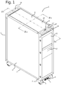
- FIG. 1 shows a perspective view of an illustrative example of an assembly 1 of a galley container 2 not part of the present invention, in the form of an aircraft trolley with a support base 3 comprising wheels 4 for transport and a locking mechanism 5 to lock the wheels.
- the assembly 1 further comprises a cooling element 6 with a front side 7 comprising a locking and release element 50 for receipt in and release from the galley container 2 of the cooling element 6 from the receiving portion 29, see Figure 3b .
- the galley container 2 further comprises a first shell, here outer shell 20, and a second shell, here inner shell 21 (see Figure 2a ), both comprising a roof element 8, 22, side walls 9, 23 and a floor element 10, 24.
- An interior 11 shown in Fig.
- the galley container 2 further comprises two handles 14, one at the front side, coinciding with the front side 7 of the cooling element 6, and one at the rear side, opposite the front side. These handles 14 are used to push, pull and steer the galley container 2 during use.
- Figure 2a shows a longitudinal cross-section view of the assembly 1 of figure 1 along line II-II.
- the galley container 2 has a door 12a at the front side and a door 12b at the rear side of the galley container.
- the door 12 comprises a first panel 15 facing the front side of the galley container 2 and a second panel 16 facing away from the front side of the galley container 2.
- a thermally insulating layer 17 is provided in between the first and second panels.
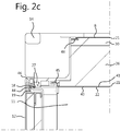
- a sealing element 18, see Figure 2c is provided between the front panel 15 and rear panel 16 of the door 12.
- the sealing element 18 is combined with a thermally insulating element 19 to prevent thermal bridges between the front panel 15 and the rear panel 16 of the door 12 and between the interior 11 and the exterior of the galley container 2, see Figure 2c .
- a second shell 21 is provided within the first shell 20 .
- a thermally insulating layer 26 (see Figure 3a ) is provided between the first and second shell.
- a connection element 27 between first shell 20 and second shell 21 comprises a thermally insulating material such that thermal bridges between the first and second shells are prevented.
- the connection element 27 is provided along the peripheral rim 48 of the first shell 20 and the peripheral rim 45 of the second shell 21, see Figs. 2c and 4b .
- the galley container 2 further has a receiving portion 29 situated between the roof element 22 of the inner second shell 21 and the roof element 8 of the outer first shell 20, shown in more detail in Fig. 2b .
- a receiving portion 29 situated between the roof element 22 of the inner second shell 21 and the roof element 8 of the outer first shell 20, shown in more detail in Fig. 2b .
- the thermally insulating layer 26 is present.
- the cooling element 6 is surrounded by this thermally insulating layer 26 present between the inner and outer shell to thermally separate the two shells.
- the thermally insulating layer 26 between the roof elements thermally insulates the cooling element 6 from the exterior heat.
- the thermal insulating layer 26 comprises a thermally insulating layer portion 30 provided against an interior side of the ceiling part 8 of the outer shell 20.
- the thermally insulating layer 26 can comprise any material with a lower thermal conductivity than metal, such as a polymer material.
- thermally insulating material are expanded polystyrene (EPS), expanded polypropylene (EPP), an aerogel or a vacuum insulated panel (VIP).
- a container 31 for containing the coolant 32 for instance blocks of dry ice, is provided.
- the container 31 further holds thermally insulating element 33 that surrounds the coolant 32 at four sides.
- the thermally insulating element 33 insulates the coolant from the surroundings of the cooling element 6 and thereby adds to the control of the dry ice dissipation rate.
- the insulating material defines the space available for the coolant 32. In case a larger volume of coolant 32 is required, the amount of insulating material 33 can be reduced or even omitted if necessary.
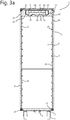
- Figure 3a shows a vertical transversal cross-section view of the assembly of figure 1 along line III-III and Figure 3b shows a detail of the top and bottom part of the assembly of Fig. 3a .
- the cooling element 6 is received within the receiving portion 29 between the parts of the thermally insulating layer 26 between the roof elements 8, 22 of the first and second shells 20, 21, respectively.
- the receiving portion 29 can be accessed through an access opening 28 between the roof elements 8, 22 of the first and second shells 20, 21, respectively, the access opening 28 having a peripheral rim 47.
- the peripheral rim 47 of the access opening 28 can be provided with a sealant (not shown) to seal the access opening 28 when the cooling element 6 is situated within the receiving portion 29.
- the cooling element 6 comprises a container 31 for containing the coolant 32, and a heat transfer element 35 to transfer heat between the container 31 and an outside of the cooling element along at least part of the container 31 and the outside of the cooling element 6.
- the container 31 is received within a housing 34 as a drawer sliding within the housing 34 enclosing the container 31, see Figure 5 .
- a sealant 49 is provided between a peripheral rim 43 of the housing 34 and the front side 7 of the container 31.
- the heat transfer element 35 is formed by a corrugated plate forming the base of the housing, wherein corrugations 38 are alternately tangential to an outside of the container 31 or to an outside of the second shell 21, thereby establishing a thermal bridge between the base of the housing 34, the base of the container 31 and the second shell 21.
- a thermal insulating material can be provided within at least some of the respective corrugations to adjust the heat transfer rate between the cooling element 6 and the second shell 21.
- tray supports that are provided at or on an inside of the second shell 21.
- Figure 3a shows tray supports 25 that protrude outwardly from the inside of the second shell 21.
- tray supports that protrude inwardly from the inside of the second shell 21, i.e. protrude inside the thermally insulating layer 26, would be possible as well.
- An advantage of this arrangement is that the thickness of the thermally insulating layer 26 between the side walls 9, 23 of the first and second shells 20, 21, respectively, can be increased, obtaining an increased insulation of the galley container.
- Fig. 3b shows that the second shell 21 comprises two layers of material, preferably being aluminium. Any other materials with good heat conductivity, preferably combined with a good strength to weight ratio, could be used as well. Additionally, the inner and outer layer could be of distinct materials. Furthermore, two or more material could be combined within at least one of the layers as well. The two layers increase the strength of the second shell 21, necessary to be able to support the trays during use.
- the inner layer 40 of the inner shell 21 is provided with the outwardly protruding tray supports 25, whereas the outer layer 41 of the inner shell 21 provides additional strength to the inner shell 21, see Figure 4b . However, it is possible to manufacture the inner shell of only one layer or more than two layers as well.
- Figure 4a shows a horizontal transversal cross-section view of the assembly 1 of figure 1 along line IV-IV in Fig. 2a .
- Inner shell 21 can be manufactured as an integral unit, but it is also possible to manufacture inner shell parts 39 and then assemble these parts 39 to form the inner shell 21.
- the inner shell parts 39 are connected along connection line 42.
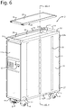
- FIG 6 shows a schematic, perspective view of an embodiment of the galley container 2 in the form of an aircraft trolley with a support base 3 comprising wheels 4 for transport and a locking mechanism 5 to lock the wheels.
- the galley container 2 further comprises a first shell, here outer shell 20, and a second shell, here inner shell 21 (see Figures 7a-c ), both comprising a roof element 8, 22, side walls 9, 23 and a floor element 10, 24.
- An interior 11 (shown in Figs. 7a-c ) of the galley container 2 can be accessed through door 12, comprising a closure mechanism 13.
- the door 12 is hingedly connected to a side wall 9 of the galley container 2.
- the galley container 2 further comprises two handles 14, one at the front side, and one at the rear side, opposite the front side.
- the roof element 8 of the outer shell 20 is formed as a lid part that is used to close the access opening 28 provided in the roof part of the galley container, of a receiving portion 29 (see fig. 7b ) and is shown separate from the galley container in figs. 6 and 7a .
- Figure 7a shows a vertical transversal cross-section view of the assembly of fig. 6 along line VII-VII
- Figures 7b and c show a detail of the top and bottom part of the galley container of Fig. 7a , respectively.
- a second shell 21 is provided within the first shell 20 .
- a thermally insulating layer 26 is provided between the first and second shell.
- a connection element 27 between first shell 20 and second shell 21 comprises a thermally insulating material such that thermal bridges between the first and second shell are prevented.
- the galley container 2 further has a receiving portion 29 situated between the roof element 22 of the inner second shell 21 and the roof element 8 of the outer first shell 20, shown in more detail in Fig. 7b .
- a thermally insulating separating wall 33 is provided between the receiving portion 29 and the roof element 22.
- a coolant can be received within the receiving portion 29 between the parts of the thermally insulating layer 26 between the roof elements 8, 22 of the first and second shells 20, 21, respectively.
- the coolant can be contained within a cooling container, such as the cooling element described above, or can be the cooling material itself.
- the coolant may be dry ice, i.e. solid carbon dioxide, having a temperature of about -80°C. However, other coolants with comparable properties as dry ice may be used as well.
- the heat transfer device 35 is formed by heat transfer plate 52 that is in thermal connection with heat pipes 36 by means of a heat transfer connection element 55.
- the heat transfer plate 52 is connected to the heat transfer connection element 55 by means of a thermally conducting element, such as a metal screw 60.
- the heat pipes 36 transport the heat from the interior 11 of the galley container 2 via element 55 and heat transfer plate 52 to the coolant in the receiving space 29.
- the heat causes evaporation of the dry ice coolant, such that the heat energy is extracted from the interior 11 of the galley container 2 that is as such cooled or at least kept at a desired temperature.
- the preferred material of the heat transfer elements 52, 55, 60 is aluminium or another material with similar light weight and heat conducting properties.
- the heat pipe 36 is provided in a cavity 56 between the inner shell 21 and the thermally insulating layer 26. Spacers 57 are used to separate the heat pipes 36 from the thermally insulating layer 26. Additionally, a free end 58 of the heat pipe 36 is engaged by a recess 59 within the insulating connection element 27 that is provided along the periphery of the access opening 28. The connection element 27 prevents the formation of thermal bridges between the outer shell and the inner shell and/or the heat pipes by means of a thermally insulating connection.
- the heat pipe 36 extends from an underside of the connection element 27 towards the bottom part of the galley container (see fig. 7c ). A number of heat pipes 36 can be provided in the cavity 56, depending on the amount of cooling needed.
- the heat pipes 36 can be evenly distributed or can be concentrated around one location.
- the heat pipes 36 are positioned in both side walls of the galley container 2, in symmetrical way, i.e. the distribution in a longitudinal direction in both side walls is similar such that a heat pipe in one side wall is opposite a heat pipe in the other side wall.
- heat pipes are shown but it will be understood that other forms of thermally conductive connections may be applied in a similar manner to collect heat from the sidewalls 23.
- the receiving portion 29 is closed by means of roof element 8 that is formed as a lid part of the top part of the galley container 2.
- the lid part is provided with a peripheral supporting rim part 54 that bears on the thermally insulating element 27.
- a sealing element 37 is provided along the periphery of the roof element 8 that seals the receiving portion 29 from the exterior of the galley container 2.
- Fig. 7b furthermore shows a peripheral edge part 53 that is connected to an upper peripheral rim or edge 51 of the first shell 20 and the connection element 27.
- the edge part 53 protects the upper peripheral edge 51 against damage by bumping or sliding against a wall or other object.
- Fig. 7c shows a detail of the bottom part of the galley container 2. It is shown that the side walls 9, 23 of the first and second shell, respectively, and the floor elements 10, 24 of the first and second shell, respectively, are connected by means of a connection element 27 that provides a thermally insulating connection between the respective side walls and floor elements, such that thermal bridges between the first and second shell and between the side walls and floor elements are prevented.
- Inner layer of second shell 10.
Landscapes
- Engineering & Computer Science (AREA)
- Chemical & Material Sciences (AREA)
- Chemical Kinetics & Catalysis (AREA)
- Combustion & Propulsion (AREA)
- Physics & Mathematics (AREA)
- Mechanical Engineering (AREA)
- Thermal Sciences (AREA)
- General Engineering & Computer Science (AREA)
- Aviation & Aerospace Engineering (AREA)
- Packages (AREA)
Description
- The invention relates to a galley container, in particular a galley container for an aircraft. Additionally, the invention relates to a cooling element to cool the interior of the galley container. Furthermore, the invention relates to an assembly of such a galley container and such a cooling element.
- During short or long journeys in a vehicle, in particular an aircraft, passengers are usually provided with at least a beverage or a snack. For this purpose, food products are carried on board of the vehicle, for example an airplane, in galley containers that can be stored in the onboard galleys. The galley container can be a galley trolley provided with wheels for transportation. To be servable, food products should be kept at a temperature less than 8°C, preferably below 5°C, until they are served, to prevent spoilage. In case the temperature of the food is at a temperature above 8°C, the food will have to be distributed within a very short time period to be able to keep up with health regulations.
- Keeping food at a temperature at 8°C, preferably below 5°C, is particularly problematic on long haul flights of 5-7 hours or longer. Even if the galley containers and their content are cool upon loading of the galley containers onboard of the aircraft, the interior of the galley containers and their contents will usually have reached a temperature above 8°C after a few hours or even less time. Food products that are still within the galley container will have to be disposed of, due to spoilage.
- Galley containers have therefore been provided with all sorts of equipment to be able to cool their interior and content for longer periods of time. Active cooling using an active cooling element within the galley container requires electrical power, such as an electrical connection to the aircraft electronic system or a built-in electrical storage, e.g. a battery. Active cooling from outside, for instance by an active cooling element in the galley itself during storage of the galley container, will require a cooling system connected to the electronic system of the aircraft.
- The above-mentioned active cooling methods have the disadvantage that electricity is needed for the cooling element to cool the galley container and its contents. In situations where electricity is not available, for instance if the aircraft's electrical system is shut down, or is defective, or if the battery is empty, cooling will not be possible and the temperature of the food product will rise, causing spoilage of the food products.
- Another method of cooling a galley container is the use of passive cooling, i.e. cooling without the need of electricity. The passive refrigeration and preservation at serving temperature of food products and beverages transported in in-flight galley containers generally takes place by means of carbon dioxide ice, or dry ice, in a sheet or pellet form. As a refrigerant, carbon dioxide ice is very effective, but is often an uneven substance that rapidly chills products and rapidly evaporates. At present, passive cooling of this type is used primarily during logistical transport of the galley container to the aircraft. Due to the inability of existing systems to maintain their temperature for a long period, such systems are not generally suitable for maintaining a low temperature during a long-haul flight. Galley containers that employ passive cooling are disclosed in
US2011/0248458 and inWO2006/093410 . These containers are arranged to allow cold air produced in a dry-ice tray to propagate from the tray into the interior of the container where the food is stored. A delivery container for temperature sensitive goods that includes a partially insulated refrigerant support tray is disclosed inWO2013/024448 . - International patent document
WO2012/056086 describes a refrigerator unit for an aircraft comprising a casing manufactured from aluminium and foamed polypropylene to which an aluminium L-shaped plate acting as a thermal conductor is attached. The casing insulates dry ice and is covered by one leg of the L-shaped plate. As the casing and the L-shaped plate are slid into a galley container, the second leg of the L-shaped plate acts as a refrigerating part to the rear and the lower parts of the galley container. - A disadvantage of the above-described refrigerator unit is that the refrigerating part of the L-shaped plate forms an extra separation within the interior of the galley container. Usually a galley container can be accessed in its full length from both the rear and the front side such that the galley container does not have to be fully turned in the limited space available in planes to be able to reach all of the interior. By inserting a refrigerator unit according to the prior art, either the front or rear side access openings are blocked by the refrigerating part of the L-shaped part. Furthermore, if the refrigerating part is located halfway the length of the galley container, the passage of trays from front to back or vice versa is blocked.
- Additionally, the above described passive refrigerator unit, but also any active cooling element, will take up valuable space within the galley container, leaving less space for food products or any other contents of the galley container. A refrigerator unit that combines a relatively small volume with passive cooling of the interior of the galley container would be desired. Still further, because of its position within the interior of the galley container, the refrigerator unit must be inserted into the container before the container is sealed, which may occur long before the container is loaded onto the airplane.
- The trolley with passive cooling described in
WO2006/093410A1 includes a top wall arranged between a cooling compartment for dry ice and the interior of the trolley body. This top wall includes through holes through which evaporated CO2 gas from the compartment can flow into the interior, driven by thermal convection. - It would be desirable to provide an alternative way to passively control cooling of food product and/or the interior of a galley container that alleviates at least some of the perceived inconveniences of the prior art.
- According to a first aspect of the invention, there is provided a galley container for an aircraft as specified in any one of
claims 1 to 15. - In a second aspect of the invention, there is provided an assembly according to
claim 16. - An illustrative example of an assembly of an insulated galley container not part of the present invention, and a cooling element and an embodiment of the galley container, will by way of non-limiting examples be described in detail with reference to the accompanying drawings. In the drawings:
-
Figure 1 shows a schematic, perspective view of an illustrative example of an assembly of a galley container and a cooling element. -
Figure 2a shows a vertical longitudinal cross-section view of the assembly ofFig. 1 along line II-II. -
Figure 2b shows a detail of the top part of the assembly ofFig. 2a . -
Figure 3a shows a vertical transversal cross-section view of the assembly ofFig. 1 along line III-III. -
Figure 3b shows a detail of the top and bottom part of the assembly ofFig. 3a . -
Figure 4a shows a horizontal transversal cross-section view of the assembly ofFig. 1 along line IV-IV inFig. 2a . -
Figure 4b shows a detail ofFig. 4a . -
Figure 5 shows a schematic perspective view of an example of the cooling element. -
Figure 6 shows a schematic, perspective view of an embodiment of the galley container according to the invention. -
Figure 7a shows a vertical transverse cross-section view of the assembly ofFig. 6 along line VII-VII. -
Figure 7b shows a detail of the top part of the assembly ofFig. 7a . -
Figure 7c shows a detail of the bottom part of the assembly ofFig. 7a . -
Figure 1 shows a perspective view of an illustrative example of anassembly 1 of agalley container 2 not part of the present invention, in the form of an aircraft trolley with asupport base 3 comprisingwheels 4 for transport and alocking mechanism 5 to lock the wheels. Theassembly 1 further comprises acooling element 6 with a front side 7 comprising a locking andrelease element 50 for receipt in and release from thegalley container 2 of thecooling element 6 from the receivingportion 29, seeFigure 3b . Thegalley container 2 further comprises a first shell, hereouter shell 20, and a second shell, here inner shell 21 (seeFigure 2a ), both comprising aroof element side walls floor element Fig. 2a ) of thegalley container 2 can be accessed throughdoor 12, comprising aclosure mechanism 13. Thedoor 12 is hingedly connected to aside wall 9 of thegalley container 2. Thegalley container 2 further comprises twohandles 14, one at the front side, coinciding with the front side 7 of thecooling element 6, and one at the rear side, opposite the front side. These handles 14 are used to push, pull and steer thegalley container 2 during use. -
Figure 2a shows a longitudinal cross-section view of theassembly 1 offigure 1 along line II-II. As can be seen, thegalley container 2 has adoor 12a at the front side and adoor 12b at the rear side of the galley container. Thedoor 12 comprises afirst panel 15 facing the front side of thegalley container 2 and asecond panel 16 facing away from the front side of thegalley container 2. In between the first and second panels, 15, 16, a thermally insulatinglayer 17 is provided. Along a peripheral rim of thedoor 12 a sealingelement 18, seeFigure 2c , is provided between thefront panel 15 andrear panel 16 of thedoor 12. The sealingelement 18 is combined with a thermally insulatingelement 19 to prevent thermal bridges between thefront panel 15 and therear panel 16 of thedoor 12 and between the interior 11 and the exterior of thegalley container 2, seeFigure 2c . - Within the
first shell 20, asecond shell 21 is provided. Between the first and second shell, a thermally insulating layer 26 (seeFigure 3a ) is provided. Aconnection element 27 betweenfirst shell 20 andsecond shell 21 comprises a thermally insulating material such that thermal bridges between the first and second shells are prevented. Theconnection element 27 is provided along theperipheral rim 48 of thefirst shell 20 and theperipheral rim 45 of thesecond shell 21, seeFigs. 2c and4b . - The
galley container 2 further has a receivingportion 29 situated between theroof element 22 of the innersecond shell 21 and theroof element 8 of the outerfirst shell 20, shown in more detail inFig. 2b . Within the receivingportion 29 thecooling element 6 is received. Between the roof elements, the thermally insulatinglayer 26 is present. Thecooling element 6 is surrounded by this thermally insulatinglayer 26 present between the inner and outer shell to thermally separate the two shells. In addition, the thermally insulatinglayer 26 between the roof elements thermally insulates thecooling element 6 from the exterior heat. The thermal insulatinglayer 26 comprises a thermally insulatinglayer portion 30 provided against an interior side of theceiling part 8 of theouter shell 20. The thermally insulatinglayer 26 can comprise any material with a lower thermal conductivity than metal, such as a polymer material. Examples of thermally insulating material are expanded polystyrene (EPS), expanded polypropylene (EPP), an aerogel or a vacuum insulated panel (VIP). - Within the
cooling element 6, acontainer 31 for containing thecoolant 32, for instance blocks of dry ice, is provided. Thecontainer 31 further holds thermally insulatingelement 33 that surrounds thecoolant 32 at four sides. The thermally insulatingelement 33 insulates the coolant from the surroundings of thecooling element 6 and thereby adds to the control of the dry ice dissipation rate. Additionally, the insulating material defines the space available for thecoolant 32. In case a larger volume ofcoolant 32 is required, the amount of insulatingmaterial 33 can be reduced or even omitted if necessary. -
Figure 3a shows a vertical transversal cross-section view of the assembly offigure 1 along line III-III andFigure 3b shows a detail of the top and bottom part of the assembly ofFig. 3a . Thecooling element 6 is received within the receivingportion 29 between the parts of the thermally insulatinglayer 26 between theroof elements second shells portion 29 can be accessed through an access opening 28 between theroof elements second shells peripheral rim 47. Theperipheral rim 47 of the access opening 28 can be provided with a sealant (not shown) to seal the access opening 28 when thecooling element 6 is situated within the receivingportion 29. Thecooling element 6 comprises acontainer 31 for containing thecoolant 32, and aheat transfer element 35 to transfer heat between thecontainer 31 and an outside of the cooling element along at least part of thecontainer 31 and the outside of thecooling element 6. Thecontainer 31 is received within ahousing 34 as a drawer sliding within thehousing 34 enclosing thecontainer 31, seeFigure 5 . To prevent leakage of exterior air to the coolant, asealant 49 is provided between aperipheral rim 43 of thehousing 34 and the front side 7 of thecontainer 31. Theheat transfer element 35 is formed by a corrugated plate forming the base of the housing, whereincorrugations 38 are alternately tangential to an outside of thecontainer 31 or to an outside of thesecond shell 21, thereby establishing a thermal bridge between the base of thehousing 34, the base of thecontainer 31 and thesecond shell 21. In addition, a thermal insulating material can be provided within at least some of the respective corrugations to adjust the heat transfer rate between the coolingelement 6 and thesecond shell 21. - During use as a galley trolley or container on board of an airplane, trays (not shown) will be stored within the
interior 11 of thegalley container 2. The trays are then supported on tray supports 25 that are provided at or on an inside of thesecond shell 21.Figure 3a shows tray supports 25 that protrude outwardly from the inside of thesecond shell 21. However, tray supports that protrude inwardly from the inside of thesecond shell 21, i.e. protrude inside the thermally insulatinglayer 26, would be possible as well. An advantage of this arrangement is that the thickness of the thermally insulatinglayer 26 between theside walls second shells -
Fig. 3b shows that thesecond shell 21 comprises two layers of material, preferably being aluminium. Any other materials with good heat conductivity, preferably combined with a good strength to weight ratio, could be used as well. Additionally, the inner and outer layer could be of distinct materials. Furthermore, two or more material could be combined within at least one of the layers as well. The two layers increase the strength of thesecond shell 21, necessary to be able to support the trays during use. Theinner layer 40 of theinner shell 21 is provided with the outwardly protruding tray supports 25, whereas theouter layer 41 of theinner shell 21 provides additional strength to theinner shell 21, seeFigure 4b . However, it is possible to manufacture the inner shell of only one layer or more than two layers as well. -
Figure 4a shows a horizontal transversal cross-section view of theassembly 1 offigure 1 along line IV-IV inFig. 2a .Inner shell 21 can be manufactured as an integral unit, but it is also possible to manufactureinner shell parts 39 and then assemble theseparts 39 to form theinner shell 21. Theinner shell parts 39 are connected alongconnection line 42. -
Figure 6 shows a schematic, perspective view of an embodiment of thegalley container 2 in the form of an aircraft trolley with asupport base 3 comprisingwheels 4 for transport and alocking mechanism 5 to lock the wheels. Thegalley container 2 further comprises a first shell, hereouter shell 20, and a second shell, here inner shell 21 (seeFigures 7a-c ), both comprising aroof element side walls floor element Figs. 7a-c ) of thegalley container 2 can be accessed throughdoor 12, comprising aclosure mechanism 13. Thedoor 12 is hingedly connected to aside wall 9 of thegalley container 2. Thegalley container 2 further comprises twohandles 14, one at the front side, and one at the rear side, opposite the front side. These handles 14 are used to push, pull and steer thegalley container 2 during use. Theroof element 8 of theouter shell 20 is formed as a lid part that is used to close the access opening 28 provided in the roof part of the galley container, of a receiving portion 29 (seefig. 7b ) and is shown separate from the galley container infigs. 6 and7a . -
Figure 7a shows a vertical transversal cross-section view of the assembly offig. 6 along line VII-VII,Figures 7b andc show a detail of the top and bottom part of the galley container ofFig. 7a , respectively. Within thefirst shell 20, asecond shell 21 is provided. Between the first and second shell, a thermally insulating layer 26 (seefigs. 7b andc ) is provided. Aconnection element 27 betweenfirst shell 20 andsecond shell 21 comprises a thermally insulating material such that thermal bridges between the first and second shell are prevented. - The
galley container 2 further has a receivingportion 29 situated between theroof element 22 of the innersecond shell 21 and theroof element 8 of the outerfirst shell 20, shown in more detail inFig. 7b . A thermally insulating separatingwall 33 is provided between the receivingportion 29 and theroof element 22. A coolant can be received within the receivingportion 29 between the parts of the thermally insulatinglayer 26 between theroof elements second shells heat transfer device 35 is formed byheat transfer plate 52 that is in thermal connection withheat pipes 36 by means of a heattransfer connection element 55. Theheat transfer plate 52 is connected to the heattransfer connection element 55 by means of a thermally conducting element, such as ametal screw 60. Theheat pipes 36 transport the heat from theinterior 11 of thegalley container 2 viaelement 55 andheat transfer plate 52 to the coolant in the receivingspace 29. The heat causes evaporation of the dry ice coolant, such that the heat energy is extracted from theinterior 11 of thegalley container 2 that is as such cooled or at least kept at a desired temperature. The preferred material of theheat transfer elements - The
heat pipe 36 is provided in acavity 56 between theinner shell 21 and the thermally insulatinglayer 26.Spacers 57 are used to separate theheat pipes 36 from the thermally insulatinglayer 26. Additionally, afree end 58 of theheat pipe 36 is engaged by arecess 59 within the insulatingconnection element 27 that is provided along the periphery of theaccess opening 28. Theconnection element 27 prevents the formation of thermal bridges between the outer shell and the inner shell and/or the heat pipes by means of a thermally insulating connection. Theheat pipe 36 extends from an underside of theconnection element 27 towards the bottom part of the galley container (seefig. 7c ). A number ofheat pipes 36 can be provided in thecavity 56, depending on the amount of cooling needed. Theheat pipes 36 can be evenly distributed or can be concentrated around one location. Theheat pipes 36 are positioned in both side walls of thegalley container 2, in symmetrical way, i.e. the distribution in a longitudinal direction in both side walls is similar such that a heat pipe in one side wall is opposite a heat pipe in the other side wall. In the illustrated embodiment, heat pipes are shown but it will be understood that other forms of thermally conductive connections may be applied in a similar manner to collect heat from thesidewalls 23. - The receiving
portion 29 is closed by means ofroof element 8 that is formed as a lid part of the top part of thegalley container 2. The lid part is provided with a peripheral supportingrim part 54 that bears on the thermally insulatingelement 27. A sealingelement 37 is provided along the periphery of theroof element 8 that seals the receivingportion 29 from the exterior of thegalley container 2. -
Fig. 7b furthermore shows aperipheral edge part 53 that is connected to an upper peripheral rim or edge 51 of thefirst shell 20 and theconnection element 27. Theedge part 53 protects the upperperipheral edge 51 against damage by bumping or sliding against a wall or other object. -
Fig. 7c shows a detail of the bottom part of thegalley container 2. It is shown that theside walls floor elements connection element 27 that provides a thermally insulating connection between the respective side walls and floor elements, such that thermal bridges between the first and second shell and between the side walls and floor elements are prevented.LIST OF PARTS 1. Assembly 32. Coolant 2. Galley container 33. Thermally insulating element 3. Support base 34. Housing 4. Wheels 35. Heat transfer element 5. Locking mechanism 36. Heat pipe 6. Cooling element 37. Sealing element 7. Front side of cooling element 38. Corrugation 8. Roof element of first shell 39. Second shell part 9. Side wall of first shell 40. Inner layer of second shell 10. Floor element of first shell 41. Outer layer of second shell 11. Interior of galley container 42. Connection line of second shell 12a + b. Door 43. Peripheral rim of housing 13. Closure mechanism 44. Peripheral rim of second panel 14. Handle 45. Peripheral rim of second shell 15. First panel of door 46. Peripheral rim of first panel 16. Second panel of door 47. Peripheral rim of access opening 17. Thermally insulating layer 48. Peripheral rim of first shell 18. Sealing element 49. Sealant 19. Thermally insulating element 50. Locking and release element. 20. First / outer shell 51. Upper peripheral edge 21. Second / inner shell 52. Heat transfer plate 22. Roof element of second shell 53. Peripheral edge part 23. Side wall of second shell 54. Peripheral supporting rim part 24. Floor element of second shell 55. Heat transfer connection element 25. Tray support element 56. Cavity 26. Thermally insulating layer 57. Spacer 27. Connection element 58. Free end of heat pipe 28. Access opening 59. Recess 29. Receiving portion 60. Screw 30. Thermally insulating layer portion 31. Container
Claims (16)
- Galley container (2) for an aircraft, comprising- a first shell (20) having a peripheral rim (48) defining an opening for access to an interior (11) of the galley container;- a second shell (21) within the first shell, having a further peripheral rim (45), the second shell being formed of a material of high thermal conductivity, wherein the second shell encloses the interior of the galley container;wherein each shell comprises a roof element (8, 22), a floor element (10, 24) and at least two sidewalls (9, 23), the galley container further comprising:- a thermally insulating layer (26, 30), thermally insulating the second shell from an exterior of the galley container;- a receiving portion (29) located above the roof element (22) of the second shell for receiving a cooling element (6) or a coolant (32), which receiving portion is provided within the first shell and is thermally insulated from the exterior of the galley container and partially thermally insulated from the second shell,- a separating wall (33) arranged between the receiving portion (29) and the roof element (22) of the second shell (21);- a heat transfer device (52, 55, 36), extending along the roof element (22) of the second shell, and from the roof element (22) towards the floor element (24) of the second shell along the interior (11) of the galley container (2) over at least a surface of the sidewalls (23) of the second shell, such that heat from the interior (11) of the galley container (2) is transferrable by thermal conduction, via the sidewalls and the heat transfer device, to the receiving portion (29); and- at least one door (12) provided at the opening to close the galley container in a closed position of the door;characterized in that the separating wall (33) forms an insulating layer that thermally insulates the roof element (22) over its entire surface, the wall being hermetic so as to prevent passage of air between the interior of the second shell and the receiving portion, and so that heat transfer from the interior (11) to the receiving portion (29) takes place primarily by the thermal conduction via the sidewalls (23).
- Galley container (2) according to claim 1, wherein the heat transfer device (52, 55, 36) is provided between the thermally insulating layer (26) and the second shell (21), wherein the heat transfer device is adjacent to the second shell.
- Galley container (2) according to any of the preceding claims, wherein the receiving portion (29) is provided between the first shell (20) and the second shell (21).
- Galley container (2) according to claim 3, wherein the receiving portion is provided between a roof element (8) of the first shell and a roof element (22) of the second shell.
- Galley container (2) according to any of the preceding claims, wherein the at least one door (12, 12') comprises- a first panel (15) facing outwards;- a second panel (16) facing the interior of the galley container; and- a thermally insulating layer (17) between the first panel and the second panel to thermally separating the first and second panel and limit heat transfer between the interior of the galley container and the exterior of the galley container when the door is in the closed position.
- Galley container (2) according to claim 5, wherein the second panel comprises a thermally insulating element (19) along at least a peripheral rim (44) of the second panel to prevent thermal bridges between the interior of the galley container and the exterior of the galley container through abutment of the second panel with the peripheral rim of the second shell when the door is in the closed position.
- Galley container (2) according to claim 5 or 6, wherein a further thermally insulating element (43) is provided between the peripheral rim of the second panel and a further peripheral rim (46) of the first panel to prevent thermal bridges between the first and second panels.
- Galley container (2) according to any of claims 6 to 7, wherein at least the second panel of the door is provided with a sealant (18) along the peripheral rim to prevent outside air entering the interior of the galley container when the door is in the closed position.
- Galley container (2) according to any of the preceding claims, wherein the receiving portion is accessible from an exterior of the galley container.
- Galley container (2) according to any of the preceding claims, wherein the first shell is provided with an access opening (28) to access the receiving portion, wherein the cooling element or coolant is receivable in the receiving portion through the access opening.
- Galley container (2) according to claim 10, wherein the access opening is provided with a closing lid to close the access opening.
- Galley container (2) according to claim 10 or 11, wherein the access opening is provided in the roof element of the first shell.
- Galley container (2) according to claim 10 or 12, wherein the access opening is provided in at least one of a front side and a rear side of the galley container.
- Galley container (2) according to any of claims 10-13, wherein between a peripheral rim (47) of the access opening and the cooling element a sealing element (49) is provided to prevent leakage to the exterior of the first shell after insertion of the cooling element.
- Galley container (2) according to any of the preceding claims, wherein an inside of the second shell is provided with a further thermally insulating layer.
- Assembly (1) of a galley container (2) according to any of the claims 1-15 and a cooling element (6), wherein the cooling element is receivable within the receiving portion (29) of the galley container, such that a heat transfer element (35) of the cooling element and the second shell (21) are connected to each other, thereby establishing a thermal connection between the cooling element and the second shell, such that heat is transferrable between the cooling element and an interior of the galley container (11) via the second shell.
Applications Claiming Priority (3)
| Application Number | Priority Date | Filing Date | Title |
|---|---|---|---|
| NL2012113A NL2012113C2 (en) | 2014-01-20 | 2014-01-20 | A galley container and a cooling element to cool the interior of the galley container. |
| NL2013506 | 2014-09-22 | ||
| PCT/NL2015/050035 WO2015108422A1 (en) | 2014-01-20 | 2015-01-20 | A galley container and a cooling element to cool the interior of the galley container |
Publications (2)
| Publication Number | Publication Date |
|---|---|
| EP3097015A1 EP3097015A1 (en) | 2016-11-30 |
| EP3097015B1 true EP3097015B1 (en) | 2021-08-11 |
Family
ID=52446417
Family Applications (1)
| Application Number | Title | Priority Date | Filing Date |
|---|---|---|---|
| EP15702596.6A Active EP3097015B1 (en) | 2014-01-20 | 2015-01-20 | A galley container and a cooling element to cool the interior of the galley container |
Country Status (4)
| Country | Link |
|---|---|
| EP (1) | EP3097015B1 (en) |
| CN (1) | CN105939931A (en) |
| SG (1) | SG11201605871UA (en) |
| WO (1) | WO2015108422A1 (en) |
Families Citing this family (6)
| Publication number | Priority date | Publication date | Assignee | Title |
|---|---|---|---|---|
| US11851270B2 (en) | 2017-10-10 | 2023-12-26 | Advanced Composite Structures, Llc | Latch for air cargo container doors |
| CN109018365B (en) * | 2018-08-07 | 2020-04-03 | 晨龙飞机(荆门)有限公司 | High-efficient safe airliner dining car of pegging graft |
| AT521596A1 (en) | 2018-09-05 | 2020-03-15 | Single Use Support Gmbh | Cooling plate assembly and method |
| EP3990271A4 (en) | 2019-06-28 | 2022-12-28 | Advanced Composite Structures, LLC | Thermally insulated air cargo container |
| US11286049B2 (en) * | 2019-11-12 | 2022-03-29 | B/E Aerospace, Inc. | Standard unit meal box compartment including air chiller |
| US12091239B2 (en) | 2021-11-11 | 2024-09-17 | Advanced Composite Structures, Llc | Formed structural panel with open core |
Family Cites Families (7)
| Publication number | Priority date | Publication date | Assignee | Title |
|---|---|---|---|---|
| US2123678A (en) * | 1937-05-01 | 1938-07-12 | Refrigerator container | |
| FR2561509A1 (en) * | 1984-03-26 | 1985-09-27 | Soceman | Trolley for serving meals on an aircraft |
| NL1028465C2 (en) | 2005-03-04 | 2006-09-06 | Driessen Aerospace Group Nv | Device for receiving objects, as well as means of transport. |
| PT2336684E (en) * | 2009-12-21 | 2013-06-17 | Messer France Sas | Filling device for filling a coolant container compartment attached to a coolant container with a cryogenic coolant |
| CA2736656C (en) * | 2010-04-11 | 2019-03-05 | Norduyn Inc. | Parts securing mechanism and method thereof |
| FI20106098A0 (en) | 2010-10-25 | 2010-10-25 | Jarmo Aurekoski | Aircraft serving trolley cooling solution |
| US20140196496A1 (en) | 2011-08-16 | 2014-07-17 | Gary Wayne Ferguson | Delivery container for temperature sensitive goods |
-
2015
- 2015-01-20 EP EP15702596.6A patent/EP3097015B1/en active Active
- 2015-01-20 CN CN201580005197.0A patent/CN105939931A/en active Pending
- 2015-01-20 SG SG11201605871UA patent/SG11201605871UA/en unknown
- 2015-01-20 WO PCT/NL2015/050035 patent/WO2015108422A1/en not_active Ceased
Non-Patent Citations (1)
| Title |
|---|
| None * |
Also Published As
| Publication number | Publication date |
|---|---|
| CN105939931A (en) | 2016-09-14 |
| WO2015108422A1 (en) | 2015-07-23 |
| EP3097015A1 (en) | 2016-11-30 |
| SG11201605871UA (en) | 2016-08-30 |
Similar Documents
| Publication | Publication Date | Title |
|---|---|---|
| EP3097015A1 (en) | A galley container and a cooling element to cool the interior of the galley container | |
| US9242732B2 (en) | Cooling solution in a trolley of an aeroplane | |
| US9303912B1 (en) | Passively cooled container system and method | |
| US5450977A (en) | Insulated shipping container | |
| CN205090700U (en) | Modular passive refrigerated container | |
| EP2350543B1 (en) | Container for storing articles at a predetermined temperature | |
| JP2014040273A (en) | Thermal management system and method | |
| JP2013249125A (en) | Low temperature container for transportation | |
| US20100282764A1 (en) | Fluid container | |
| JP3206373U (en) | Refrigerated container for rail freight transportation equipped with electrostatic field forming device | |
| US9395116B1 (en) | Dual temperature insulated container | |
| US3638443A (en) | Spray refrigeration system for freeze-sensitive product | |
| US20220242568A1 (en) | Container for storing and serving frozen confectionery items | |
| CN103950645A (en) | Passive vehicle-mounted chill box | |
| US12396553B2 (en) | Container for storing and serving frozen confectionery items | |
| NL2012113C2 (en) | A galley container and a cooling element to cool the interior of the galley container. | |
| US12595118B2 (en) | High-surface area thermal protection modules for cargo containers and cargo containers including the same | |
| US20190241348A1 (en) | Conservation insulated container and/or transportation of perishable or heat sensitive products | |
| US20240343467A1 (en) | Shipping container for shipping temperature-sensitive transport material | |
| CN206984771U (en) | Integral type is layered Cold Chain Logistics mobile refrigerating case | |
| JP7693231B2 (en) | Trolley | |
| CN211944236U (en) | Dual-temperature-zone specimen transportation device | |
| CN219193249U (en) | Temperature control container | |
| EP4516672B1 (en) | Integrated chilling unit for an aircraft galley | |
| RU2535502C1 (en) | Container to transport and store products with maintenance of temperature conditions |
Legal Events
| Date | Code | Title | Description |
|---|---|---|---|
| PUAI | Public reference made under article 153(3) epc to a published international application that has entered the european phase |
Free format text: ORIGINAL CODE: 0009012 |
|
| 17P | Request for examination filed |
Effective date: 20160628 |
|
| AK | Designated contracting states |
Kind code of ref document: A1 Designated state(s): AL AT BE BG CH CY CZ DE DK EE ES FI FR GB GR HR HU IE IS IT LI LT LU LV MC MK MT NL NO PL PT RO RS SE SI SK SM TR |
|
| AX | Request for extension of the european patent |
Extension state: BA ME |
|
| DAX | Request for extension of the european patent (deleted) | ||
| STAA | Information on the status of an ep patent application or granted ep patent |
Free format text: STATUS: EXAMINATION IS IN PROGRESS |
|
| 17Q | First examination report despatched |
Effective date: 20180717 |
|
| RAP1 | Party data changed (applicant data changed or rights of an application transferred) |
Owner name: SAFRAN CABIN CATERING B.V. |
|
| GRAP | Despatch of communication of intention to grant a patent |
Free format text: ORIGINAL CODE: EPIDOSNIGR1 |
|
| STAA | Information on the status of an ep patent application or granted ep patent |
Free format text: STATUS: GRANT OF PATENT IS INTENDED |
|
| INTG | Intention to grant announced |
Effective date: 20210218 |
|
| GRAJ | Information related to disapproval of communication of intention to grant by the applicant or resumption of examination proceedings by the epo deleted |
Free format text: ORIGINAL CODE: EPIDOSDIGR1 |
|
| STAA | Information on the status of an ep patent application or granted ep patent |
Free format text: STATUS: EXAMINATION IS IN PROGRESS |
|
| GRAP | Despatch of communication of intention to grant a patent |
Free format text: ORIGINAL CODE: EPIDOSNIGR1 |
|
| STAA | Information on the status of an ep patent application or granted ep patent |
Free format text: STATUS: GRANT OF PATENT IS INTENDED |
|
| INTC | Intention to grant announced (deleted) | ||
| INTG | Intention to grant announced |
Effective date: 20210420 |
|
| GRAS | Grant fee paid |
Free format text: ORIGINAL CODE: EPIDOSNIGR3 |
|
| GRAA | (expected) grant |
Free format text: ORIGINAL CODE: 0009210 |
|
| STAA | Information on the status of an ep patent application or granted ep patent |
Free format text: STATUS: THE PATENT HAS BEEN GRANTED |
|
| AK | Designated contracting states |
Kind code of ref document: B1 Designated state(s): AL AT BE BG CH CY CZ DE DK EE ES FI FR GB GR HR HU IE IS IT LI LT LU LV MC MK MT NL NO PL PT RO RS SE SI SK SM TR |
|
| REG | Reference to a national code |
Ref country code: CH Ref legal event code: EP |
|
| REG | Reference to a national code |
Ref country code: DE Ref legal event code: R096 Ref document number: 602015072150 Country of ref document: DE |
|
| REG | Reference to a national code |
Ref country code: IE Ref legal event code: FG4D Ref country code: AT Ref legal event code: REF Ref document number: 1419153 Country of ref document: AT Kind code of ref document: T Effective date: 20210915 |
|
| REG | Reference to a national code |
Ref country code: LT Ref legal event code: MG9D |
|
| REG | Reference to a national code |
Ref country code: NL Ref legal event code: MP Effective date: 20210811 |
|
| REG | Reference to a national code |
Ref country code: AT Ref legal event code: MK05 Ref document number: 1419153 Country of ref document: AT Kind code of ref document: T Effective date: 20210811 |
|
| PG25 | Lapsed in a contracting state [announced via postgrant information from national office to epo] |
Ref country code: HR Free format text: LAPSE BECAUSE OF FAILURE TO SUBMIT A TRANSLATION OF THE DESCRIPTION OR TO PAY THE FEE WITHIN THE PRESCRIBED TIME-LIMIT Effective date: 20210811 Ref country code: RS Free format text: LAPSE BECAUSE OF FAILURE TO SUBMIT A TRANSLATION OF THE DESCRIPTION OR TO PAY THE FEE WITHIN THE PRESCRIBED TIME-LIMIT Effective date: 20210811 Ref country code: SE Free format text: LAPSE BECAUSE OF FAILURE TO SUBMIT A TRANSLATION OF THE DESCRIPTION OR TO PAY THE FEE WITHIN THE PRESCRIBED TIME-LIMIT Effective date: 20210811 Ref country code: BG Free format text: LAPSE BECAUSE OF FAILURE TO SUBMIT A TRANSLATION OF THE DESCRIPTION OR TO PAY THE FEE WITHIN THE PRESCRIBED TIME-LIMIT Effective date: 20211111 Ref country code: AT Free format text: LAPSE BECAUSE OF FAILURE TO SUBMIT A TRANSLATION OF THE DESCRIPTION OR TO PAY THE FEE WITHIN THE PRESCRIBED TIME-LIMIT Effective date: 20210811 Ref country code: LT Free format text: LAPSE BECAUSE OF FAILURE TO SUBMIT A TRANSLATION OF THE DESCRIPTION OR TO PAY THE FEE WITHIN THE PRESCRIBED TIME-LIMIT Effective date: 20210811 Ref country code: FI Free format text: LAPSE BECAUSE OF FAILURE TO SUBMIT A TRANSLATION OF THE DESCRIPTION OR TO PAY THE FEE WITHIN THE PRESCRIBED TIME-LIMIT Effective date: 20210811 Ref country code: ES Free format text: LAPSE BECAUSE OF FAILURE TO SUBMIT A TRANSLATION OF THE DESCRIPTION OR TO PAY THE FEE WITHIN THE PRESCRIBED TIME-LIMIT Effective date: 20210811 Ref country code: PT Free format text: LAPSE BECAUSE OF FAILURE TO SUBMIT A TRANSLATION OF THE DESCRIPTION OR TO PAY THE FEE WITHIN THE PRESCRIBED TIME-LIMIT Effective date: 20211213 Ref country code: NO Free format text: LAPSE BECAUSE OF FAILURE TO SUBMIT A TRANSLATION OF THE DESCRIPTION OR TO PAY THE FEE WITHIN THE PRESCRIBED TIME-LIMIT Effective date: 20211111 |
|
| PG25 | Lapsed in a contracting state [announced via postgrant information from national office to epo] |
Ref country code: PL Free format text: LAPSE BECAUSE OF FAILURE TO SUBMIT A TRANSLATION OF THE DESCRIPTION OR TO PAY THE FEE WITHIN THE PRESCRIBED TIME-LIMIT Effective date: 20210811 Ref country code: LV Free format text: LAPSE BECAUSE OF FAILURE TO SUBMIT A TRANSLATION OF THE DESCRIPTION OR TO PAY THE FEE WITHIN THE PRESCRIBED TIME-LIMIT Effective date: 20210811 Ref country code: GR Free format text: LAPSE BECAUSE OF FAILURE TO SUBMIT A TRANSLATION OF THE DESCRIPTION OR TO PAY THE FEE WITHIN THE PRESCRIBED TIME-LIMIT Effective date: 20211112 |
|
| PG25 | Lapsed in a contracting state [announced via postgrant information from national office to epo] |
Ref country code: NL Free format text: LAPSE BECAUSE OF FAILURE TO SUBMIT A TRANSLATION OF THE DESCRIPTION OR TO PAY THE FEE WITHIN THE PRESCRIBED TIME-LIMIT Effective date: 20210811 |
|
| PG25 | Lapsed in a contracting state [announced via postgrant information from national office to epo] |
Ref country code: DK Free format text: LAPSE BECAUSE OF FAILURE TO SUBMIT A TRANSLATION OF THE DESCRIPTION OR TO PAY THE FEE WITHIN THE PRESCRIBED TIME-LIMIT Effective date: 20210811 |
|
| REG | Reference to a national code |
Ref country code: DE Ref legal event code: R097 Ref document number: 602015072150 Country of ref document: DE |
|
| PG25 | Lapsed in a contracting state [announced via postgrant information from national office to epo] |
Ref country code: SM Free format text: LAPSE BECAUSE OF FAILURE TO SUBMIT A TRANSLATION OF THE DESCRIPTION OR TO PAY THE FEE WITHIN THE PRESCRIBED TIME-LIMIT Effective date: 20210811 Ref country code: SK Free format text: LAPSE BECAUSE OF FAILURE TO SUBMIT A TRANSLATION OF THE DESCRIPTION OR TO PAY THE FEE WITHIN THE PRESCRIBED TIME-LIMIT Effective date: 20210811 Ref country code: RO Free format text: LAPSE BECAUSE OF FAILURE TO SUBMIT A TRANSLATION OF THE DESCRIPTION OR TO PAY THE FEE WITHIN THE PRESCRIBED TIME-LIMIT Effective date: 20210811 Ref country code: EE Free format text: LAPSE BECAUSE OF FAILURE TO SUBMIT A TRANSLATION OF THE DESCRIPTION OR TO PAY THE FEE WITHIN THE PRESCRIBED TIME-LIMIT Effective date: 20210811 Ref country code: CZ Free format text: LAPSE BECAUSE OF FAILURE TO SUBMIT A TRANSLATION OF THE DESCRIPTION OR TO PAY THE FEE WITHIN THE PRESCRIBED TIME-LIMIT Effective date: 20210811 Ref country code: AL Free format text: LAPSE BECAUSE OF FAILURE TO SUBMIT A TRANSLATION OF THE DESCRIPTION OR TO PAY THE FEE WITHIN THE PRESCRIBED TIME-LIMIT Effective date: 20210811 |
|
| PLBE | No opposition filed within time limit |
Free format text: ORIGINAL CODE: 0009261 |
|
| STAA | Information on the status of an ep patent application or granted ep patent |
Free format text: STATUS: NO OPPOSITION FILED WITHIN TIME LIMIT |
|
| 26N | No opposition filed |
Effective date: 20220512 |
|
| PG25 | Lapsed in a contracting state [announced via postgrant information from national office to epo] |
Ref country code: IT Free format text: LAPSE BECAUSE OF FAILURE TO SUBMIT A TRANSLATION OF THE DESCRIPTION OR TO PAY THE FEE WITHIN THE PRESCRIBED TIME-LIMIT Effective date: 20210811 |
|
| PG25 | Lapsed in a contracting state [announced via postgrant information from national office to epo] |
Ref country code: SI Free format text: LAPSE BECAUSE OF FAILURE TO SUBMIT A TRANSLATION OF THE DESCRIPTION OR TO PAY THE FEE WITHIN THE PRESCRIBED TIME-LIMIT Effective date: 20210811 Ref country code: MC Free format text: LAPSE BECAUSE OF FAILURE TO SUBMIT A TRANSLATION OF THE DESCRIPTION OR TO PAY THE FEE WITHIN THE PRESCRIBED TIME-LIMIT Effective date: 20210811 |
|
| REG | Reference to a national code |
Ref country code: CH Ref legal event code: PL |
|
| REG | Reference to a national code |
Ref country code: BE Ref legal event code: MM Effective date: 20220131 |
|
| PG25 | Lapsed in a contracting state [announced via postgrant information from national office to epo] |
Ref country code: LU Free format text: LAPSE BECAUSE OF NON-PAYMENT OF DUE FEES Effective date: 20220120 |
|
| PG25 | Lapsed in a contracting state [announced via postgrant information from national office to epo] |
Ref country code: BE Free format text: LAPSE BECAUSE OF NON-PAYMENT OF DUE FEES Effective date: 20220131 |
|
| PG25 | Lapsed in a contracting state [announced via postgrant information from national office to epo] |
Ref country code: LI Free format text: LAPSE BECAUSE OF NON-PAYMENT OF DUE FEES Effective date: 20220131 Ref country code: CH Free format text: LAPSE BECAUSE OF NON-PAYMENT OF DUE FEES Effective date: 20220131 |
|
| PG25 | Lapsed in a contracting state [announced via postgrant information from national office to epo] |
Ref country code: IE Free format text: LAPSE BECAUSE OF NON-PAYMENT OF DUE FEES Effective date: 20220120 |
|
| PGFP | Annual fee paid to national office [announced via postgrant information from national office to epo] |
Ref country code: GB Payment date: 20221221 Year of fee payment: 9 Ref country code: FR Payment date: 20221220 Year of fee payment: 9 |
|
| PGFP | Annual fee paid to national office [announced via postgrant information from national office to epo] |
Ref country code: DE Payment date: 20221220 Year of fee payment: 9 |
|
| PG25 | Lapsed in a contracting state [announced via postgrant information from national office to epo] |
Ref country code: HU Free format text: LAPSE BECAUSE OF FAILURE TO SUBMIT A TRANSLATION OF THE DESCRIPTION OR TO PAY THE FEE WITHIN THE PRESCRIBED TIME-LIMIT; INVALID AB INITIO Effective date: 20150120 |
|
| PG25 | Lapsed in a contracting state [announced via postgrant information from national office to epo] |
Ref country code: MK Free format text: LAPSE BECAUSE OF FAILURE TO SUBMIT A TRANSLATION OF THE DESCRIPTION OR TO PAY THE FEE WITHIN THE PRESCRIBED TIME-LIMIT Effective date: 20210811 Ref country code: CY Free format text: LAPSE BECAUSE OF FAILURE TO SUBMIT A TRANSLATION OF THE DESCRIPTION OR TO PAY THE FEE WITHIN THE PRESCRIBED TIME-LIMIT Effective date: 20210811 |
|
| PG25 | Lapsed in a contracting state [announced via postgrant information from national office to epo] |
Ref country code: TR Free format text: LAPSE BECAUSE OF FAILURE TO SUBMIT A TRANSLATION OF THE DESCRIPTION OR TO PAY THE FEE WITHIN THE PRESCRIBED TIME-LIMIT Effective date: 20210811 |
|
| REG | Reference to a national code |
Ref country code: DE Ref legal event code: R119 Ref document number: 602015072150 Country of ref document: DE |
|
| GBPC | Gb: european patent ceased through non-payment of renewal fee |
Effective date: 20240120 |
|
| PG25 | Lapsed in a contracting state [announced via postgrant information from national office to epo] |
Ref country code: MT Free format text: LAPSE BECAUSE OF FAILURE TO SUBMIT A TRANSLATION OF THE DESCRIPTION OR TO PAY THE FEE WITHIN THE PRESCRIBED TIME-LIMIT Effective date: 20210811 |
|
| PG25 | Lapsed in a contracting state [announced via postgrant information from national office to epo] |
Ref country code: DE Free format text: LAPSE BECAUSE OF NON-PAYMENT OF DUE FEES Effective date: 20240801 |
|
| PG25 | Lapsed in a contracting state [announced via postgrant information from national office to epo] |
Ref country code: GB Free format text: LAPSE BECAUSE OF NON-PAYMENT OF DUE FEES Effective date: 20240120 |
|
| PG25 | Lapsed in a contracting state [announced via postgrant information from national office to epo] |
Ref country code: FR Free format text: LAPSE BECAUSE OF NON-PAYMENT OF DUE FEES Effective date: 20240131 |
|
| PG25 | Lapsed in a contracting state [announced via postgrant information from national office to epo] |
Ref country code: GB Free format text: LAPSE BECAUSE OF NON-PAYMENT OF DUE FEES Effective date: 20240120 Ref country code: FR Free format text: LAPSE BECAUSE OF NON-PAYMENT OF DUE FEES Effective date: 20240131 Ref country code: DE Free format text: LAPSE BECAUSE OF NON-PAYMENT OF DUE FEES Effective date: 20240801 |