EP3096597B1 - Method and implement regulation device for an agricultural machine - Google Patents
Method and implement regulation device for an agricultural machine Download PDFInfo
- Publication number
- EP3096597B1 EP3096597B1 EP15740566.3A EP15740566A EP3096597B1 EP 3096597 B1 EP3096597 B1 EP 3096597B1 EP 15740566 A EP15740566 A EP 15740566A EP 3096597 B1 EP3096597 B1 EP 3096597B1
- Authority
- EP
- European Patent Office
- Prior art keywords
- shaft
- screw
- tied
- coupling
- end portion
- Prior art date
- Legal status (The legal status is an assumption and is not a legal conclusion. Google has not performed a legal analysis and makes no representation as to the accuracy of the status listed.)
- Active
Links
Images





Classifications
-
- A—HUMAN NECESSITIES
- A01—AGRICULTURE; FORESTRY; ANIMAL HUSBANDRY; HUNTING; TRAPPING; FISHING
- A01B—SOIL WORKING IN AGRICULTURE OR FORESTRY; PARTS, DETAILS, OR ACCESSORIES OF AGRICULTURAL MACHINES OR IMPLEMENTS, IN GENERAL
- A01B23/00—Elements, tools, or details of harrows
- A01B23/06—Discs; Scrapers for cleaning discs; Sharpening attachments
-
- A—HUMAN NECESSITIES
- A01—AGRICULTURE; FORESTRY; ANIMAL HUSBANDRY; HUNTING; TRAPPING; FISHING
- A01B—SOIL WORKING IN AGRICULTURE OR FORESTRY; PARTS, DETAILS, OR ACCESSORIES OF AGRICULTURAL MACHINES OR IMPLEMENTS, IN GENERAL
- A01B35/00—Other machines for working soil
- A01B35/20—Tools; Details
- A01B35/28—Rotating tools; Mounting rotating tools
-
- A—HUMAN NECESSITIES
- A01—AGRICULTURE; FORESTRY; ANIMAL HUSBANDRY; HUNTING; TRAPPING; FISHING
- A01B—SOIL WORKING IN AGRICULTURE OR FORESTRY; PARTS, DETAILS, OR ACCESSORIES OF AGRICULTURAL MACHINES OR IMPLEMENTS, IN GENERAL
- A01B71/00—Construction or arrangement of setting or adjusting mechanisms, of implement or tool drive or of power take-off; Means for protecting parts against dust, or the like; Adapting machine elements to or for agricultural purposes
- A01B71/04—Bearings of rotating parts, e.g. for soil-working discs
Definitions
- the present invention is related to a method for an agricultural machine according to the pre-characterising portion of patent claim 1.
- the invention is also related to an implement regulation device for carrying out the method according to the pre-characterising portion of patent claim 6.
- the machine type needs to be very flexible and should be adjustable for different types of running.
- the machine type was provided with discs which have a firm cutting angle of about 16-18 degrees.
- Some machines have been provided with adjustable angle adjustment, but as those were quite complicated devices, those machines have hardly been established on the market. It is desirable with a simple and durable device to adjust the cutting angle which is required at a certain type of cultivation circumstances. In principle this is so that a high cutting angle of about 18 degrees is possible at a limited straw quantity and a small working depth.
- the cutting angle must be less than about 12-14 degrees to make possible a run free from interference. This is in some extent also connected to which hoeing degree the disc is provided with.
- the object of the present invention is to provide a method and an implement regulation device for an agricultural machine of the type mentioned above, which solves the problems mentioned above.
- the hub of the discs with a shaft which is provided with an angle of some degrees and simultaneously provides so that it can be rotated and be fixed in different positions, one achieves an adjustable disc angle.
- the possible angle variation will be the double turning angle of the shaft. This is among others known through prototypes which are manufactured. Only this solution is however not sufficient because it is very difficult, after a period of use, to turn the shaft as soil, dirt and rust makes that the shaft jams in the casing.
- the improved solution according to the invention consists in that the shaft is given a form tied and force tied security against the lower end of the arm. To be able to loosen the shaft at change of the working angle of the disc the shaft is preferably given a substantially conical form, i.e.
- the disc can be provided with an adjustability which only has a marginal cost influence and is durable and maintenance free.
- This solution means that one and only machine can be used under many different circumstances at different working depths.
- the joint can be made short and compact to facilitate going through of straw, soil and the plant rests.
- the conical form implies that the axial force which is taken up by the bearing acts in the direction to press in the shaft in the substantially conically formed hole, which in turn contributes to a stable joint.
- an agricultural machine 1 is shown in a working position.
- the agricultural machine 1 has a frame 2 and a towing device 2a, which suitably is connectable to and can be towed by a not shown tractor.
- the machine 1 consists here of three rows a, b, c of implements in form of two former rows a, b of soil working, free rotatable, discs 3 and a rear row c with roller aggregates 4.
- Each disc 3 in one of the both rows a, b is turned to the opposite direction in comparison with corresponding discs in the second row b and a, respectively.
- the discs 3 are provided in figs.
- a first embodiment of the method according to the invention is shown in greater detail to change the adjustment of an implement and even a first embodiment of the implement regulation device to carry out the method.
- each disc 103 is accordingly fastened at the hub 20, which is freely journaled about a bearing portion 121b, which has the form of a substantially circular cylindrical part 21b of a shaft 21.
- the opposite end of the shaft 21 constitutes of a conical part 21a, which has the form of a substantially or partly conical part 21a.
- the upper end of the arm 10 is provided with a bearing means 13, as a rubber spring or other flexible suspension.
- the bearing means 13 consists in a known way of two bearing halves, the lower bearing half being connected to the arm and the upper bearing half is by means of a screw/nut joint fastened at the lower bearing half.
- the beams 11 and 12 see fig.
- the shaft 21 is rotatable journaled in a bearing 20a in the hub 20.
- the shaft 21 is angled preferably a few degrees ⁇ according to fig. 3 between the centre axis of the substantially conical part 21a and the centre axis of the circular cylindrical part 21b which is placed in the bearing 20a.
- the shaft 21 can be rotated and locked between at least two positions, so that an adjustable disc angle is achieved.
- the angle between the substantially conical part 21a and the circular cylindrical part 21b of the shaft 21 is an angle ⁇ .
- substantially conical part 21a of the shaft is rotated for instance 180 degrees in a corresponding substantially or partly conical hole 24 in the end part 23 of the arm 10 to another position means that the disc angle in relation to the partly conical part 21a can be amended to maximal 2 ⁇ .
- ⁇ can be about 2 degrees and 2 ⁇ accordingly be about 4 degrees.
- Other wished position of the shaft 21 and the thereby values of the angle ⁇ are naturally also possible within the scope of the patent claims.
- the circular cylindrical part 21b of the bearing has on its towards the disc 3 faced side a protruding part 16 with a cut in 14 which extends in the circumferential direction and is provided at the circular cylindrical part 21b to receive a locking dasher 15 to fasten the shaft 21 at the inner bearing half of the hub 20.
- the shaft 21 is in the circumferential direction provided with a pre-determined number of chamfered surfaces 33 between the conical surfaces 34 of the partly conical part 21a which together correspond to the form in the partly conical hole 24 in the end portion 23.
- the intended working angle is fixed by tightening a screw joint 30, as the chamfered surfaces meet correspondingly intended surfaces in the end part 23.
- Other configurations of the shaft form and the corresponding form of the hole are of course possible, as is described below.
- the outer form of the partly conical part 21a of the shaft 21 shall correspond to the form of the receiving hole 24 in the end portion 23 of the arm 10, whereby a form tied and force tied coupling is achieved in at least two positions.
- the partly conical part 21a can be formed, so that it comprise chamfered surfaces whish are preferably constantly distributed in the circumferential direction, preferably being of a constant number and preferably four in number.
- the shaft 21 consists also of another substantially or partly cylindrical part 21c between the partly conical part 21a which can be introduced in the cylindrical end portion 23 of the arm and the circular cylindrical part 21b which exists in the bearing.
- This part 21c has in the circumferential direction distributed plain portions 35 to by means of a tool, as a not shown wrench, be able to rotate the conical part 21a of the shaft 21 in the cylindrical end portion 23 of the arm at the changing of the position of the shaft 21 and thereby also of the disc 3.
- the threaded part of the threaded hole 32 should be so long, that by loosening the screw 30 to rotate the shaft 21 to a new intended position, the screw is still engaged with said threaded part.
- the hole 31 in the end portion 23 is widened with a countersink 36 so that the head 37 of the screw 30 can be countersinked therein by tightening.
- the head of the screw is of a hexagon type, but can also be of another type, as a cap screw, a torq screw, a cross headed screw or a slotted screw.
- the screw joint can consist of a threaded rod which extends out from the coupling part 21a of the shaft 21, which rod can receive a nut which is tightened at the outer side of the end portion 23 by tightening the screw joint.
- the end portion 23 of the arm 10 has a preferably partly conical, towards the partly conical part 21a formed corresponding with the chamfered provided hole 24. With a couple of easy handgrips the adjustment (rotating of the shaft 21) can be performed to a new position for the disc 3.
- the coupling part 21 a can be formed in a number of ways which make it possible to achieve a form tied and power tied coupling with the end portion 23 of the arm 10.
- the section of the coupling part 21a should be uniformed with reduced section area seen from the bearing part 21b to make an easy adjustment possible.
- the section can accordingly be polygon formed.
- the receiving hole 24 has preferably a form which corresponds to the form of the coupling part 21a.
- the form of the hole 24 needs however not identically correspond to the form of the coupling part 21a, as long as the form tied and the power tied coupling between them can be achieved in a desired intended number of pre-determined positions.
- each disc 103 is accordingly fastened at the hub 120, which is freely journaled about a bearing portion 121b of a shaft 121, the bearing portion 121b having a substantially circular cylindrical form.
- the opposite end of the shaft 121 constitutes of a coupling part 121a, which has a substantially conical form.
- the upper end of an arm 110 is provided with a bearing means 113, as a rubber spring or other flexible suspension.
- the bearing means 113 consists in a known way of two bearing halves, the lower bearing half being connected to the arm and the upper bearing half is by means of a screw/nut joint fastened at the lower bearing half.
- the beams 11 and 12 see fig.
- the discs 103 are suitably screw tightened at the hubs 120 by means of screw joints 122 provided in the circumferential direction.
- the shaft 121 is rotatably journaled in a bearing 120a in the hub 120.
- the shaft 121 is angled preferably a few degrees ⁇ according to fig. 6 between the centre axis of the substantially conical part 121a and the centre axis of the circular cylindrical part 121b which is existing in the bearing 120a.
- the shaft 121 can be rotated and fixed between at least two positions, so that an adjustable disc angle is achieved.
- the angle between the substantially conical part 121a and the circular cylindrical part 121b of the shaft 121 is an angle ⁇ .
- substantially conical part 121a of the shaft is rotated for instance 180 degrees in a corresponding substantially or partly conical hole 124 in the end part 123 of the arm 110 to another position means that the disc angle in relation to the partly conical part 121a can be amended to maximal 2 ⁇ .
- ⁇ can be about 2 degrees and 2 ⁇ accordingly be about 4 degrees.
- Other wished position of the shaft 121 and thereby values of the angle ⁇ are naturally also possible within the scope of the patent claims.
- the circular cylindrical part 121b of the bearing has on its towards the disc 103 faced side a protruding threaded part 114 to receive a nut 115 to fasten the shaft 121 at the inner bearing half of the hub 120.
- the shaft 121 also consists of another substantially cylindrical part 121c between the conical part 121a which can be introduced in the cylindrical end portion 123 of the arm and the circular cylindrical part 121b which exists in the bearing.
- This part 121c has in the circumferential direction distributed plain parts 135 to by means of a tool, as a not shown wrench, can rotate the shaft 121 the conical part 121a of the shaft 121 in the cylindrical end portion 123 of the arm at the changing of the position of the shaft 121 and thereby also of the disc 103.
- the threaded part of the threaded hole 132 should be so long, that by loosening the screw 130 to rotate the shaft 121 to a new intended position, the screw 130 is still engaged with said threaded part.
- the hole 131 in the end portion 123 is widened with a countersink 136 so that the head 137 of the screw 130 can be countersinked therein.
- the head 137 of the screw 130 is of a hexagon type, but can also be of another type, as a cap screw, a torq screw, a cross headed screw or a slotted screw.
- the screw joint can consist of a threaded rod which protrudes out from the couplings part 121a of the shaft 121, which rod can receive a nut which is tightened at the outer side of the end portion 123 by tightening the screw joint.
- the end portion 123 of the arm 110 has a preferably conical, towards the partly conical part 121a form corresponding hole 124. With a couple of easy handgrips the adjustment (rotating of the shaft 121) can be performed to a new position for the disc 103.
- an area with a profiled, roundabout extended part 142 which is faced against the opening of the hole in the axial direction towards the conical end of the shaft 121 and which form a symmetrical form with frequent parts.
- a profiled, roundabout extended part 142 which is faced against the opening of the hole in the axial direction towards the conical end of the shaft 121 and which form symmetrically frequent symmetrical positions to fit to the form of the profiled roundabout part 142.
- the shaft 121 As the conical end part 121a of the shaft 121 is led in with its conical point into the conical hole 124 of the end part 123 and the screw 130 is tightened the profiled parts 142 and 143, which are faced towards each other, are pressed against each other and are moved into engagement with each other in intended positions, the shaft 121being for example able to adopt two or more distinct positions in relation to the end portion. These positions correspond to the different angle positions of the disc 103 in relation to the arm 110, which has been described above in connection with the angle ⁇ .
- the profiled parts 142, 143 can be formed in different ways to give the conical part 121a of the shaft 121 at least two distinct positions in the conical hole 124.
- the section of the conical part 121c of the shaft 121 should therefore have a circular form to easy adjustment to intended positions.
- markings 145 can be provided on the mid part 121c of the shaft for visual marking of the different positions of the conical part 121a of the shaft 121 in relation to the hole 124.
- the form of the hole does not be identically correspond to the form of the coupling part 121a as long as a form tied and force tied coupling can be achieved between them in intended pre-determined positions.
- the method and the implement regulation device according to the invention is to its construction not limited to the embodiments shown in figs. 1-9 , but can be modified within the scope of the accompanying claims.
Landscapes
- Life Sciences & Earth Sciences (AREA)
- Engineering & Computer Science (AREA)
- Mechanical Engineering (AREA)
- Soil Sciences (AREA)
- Environmental Sciences (AREA)
- Agricultural Machines (AREA)
- Soil Working Implements (AREA)
Description
- The present invention is related to a method for an agricultural machine according to the pre-characterising portion of patent claim 1. The invention is also related to an implement regulation device for carrying out the method according to the pre-characterising portion of patent claim 6.
- During late years it has been more common with agricultural implements with discs in two parallel rows, for example as those who are sold under the trade name "Carrier" by Väderstad-Verken AB. This machine type shows many characteristics which are appreciated by the farmers. With the spreading of the machine type the machines are used at many different cultivation circumstances with many types of crops in many climate zones, at different soil types etc. The machine type, which is a special type of disc implement, is intended to cultivate the soil and to cultivate down harvest rests as straw, stubble and even weeds. After harvesting of corn there are big quantities of harvest rests on the ground, often stands corn stems meter high left. This provides great demands on the ability of the machine to let through big quantities of harvest rests without stop. This will be special demanding if one simultaneously wants to drive relatively deep. After harvesting of oil plants the customer often wants to "strip off' the whole ground, but cultivate the soil very shallow. In this case a high angle of action is very important. In other cases, especially in the spring, the customer maybe only wants to cultivate the soil relatively deep to cultivate in "the heat" in the soil, i.e. one turns up cold deeper laying soil which is exposed to the sun to heat up volume of the soil. This can be especially important at late sowing of corn, which demands a warm soil to be well developed.
- Of the above it is evident that the machine type needs to be very flexible and should be adjustable for different types of running. Commonly is that the machine type was provided with discs which have a firm cutting angle of about 16-18 degrees. Some machines have been provided with adjustable angle adjustment, but as those were quite complicated devices, those machines have hardly been established on the market. It is desirable with a simple and durable device to adjust the cutting angle which is required at a certain type of cultivation circumstances. In principle this is so that a high cutting angle of about 18 degrees is possible at a limited straw quantity and a small working depth.
- A previously known device is shown in
US 1,042,651 wherein the shaft at the hub of the disc can be fastened in different angles by means of a locking screw which is radially led through a threaded hole in the hub of the disc. This device is not quite secure as the shaft easily can glide in the hub hole or can the screw simply be broken. A device according to the preamble of claim 6 is shown inWO 02/19791 A1 - At need of greater working depths and in combination with greater quantities of harvest rests the cutting angle must be less than about 12-14 degrees to make possible a run free from interference. This is in some extent also connected to which hoeing degree the disc is provided with.
- The object of the present invention is to provide a method and an implement regulation device for an agricultural machine of the type mentioned above, which solves the problems mentioned above.
- The object is achieved with a method and an implement regulation device for an agricultural machine, which has been given the characterizing features of the independent claims 1 and 6, respectively.
- Preferred embodiments of the method and the implement regulation device according to the invention have been given the characteristics which are apparent from the subclaims.
- If one provides the hub of the discs with a shaft which is provided with an angle of some degrees and simultaneously provides so that it can be rotated and be fixed in different positions, one achieves an adjustable disc angle. The possible angle variation will be the double turning angle of the shaft. This is among others known through prototypes which are manufactured. Only this solution is however not sufficient because it is very difficult, after a period of use, to turn the shaft as soil, dirt and rust makes that the shaft jams in the casing. The improved solution according to the invention consists in that the shaft is given a form tied and force tied security against the lower end of the arm. To be able to loosen the shaft at change of the working angle of the disc the shaft is preferably given a substantially conical form, i.e. in the circumferential direction substantially or in the hole conical with the provided corresponding chamfered or corresponding, in the direction of the axel/shaft portions by which a form tied and force tied coupling is achieved. In this way a controlled possibility is given to move the shaft outwards by adjusting. The adjustment would then be very simple and can be carried out with a couple of simple handgrips. By loosening the shaft in the conical hole by partially screwing out a centrally in the shaft fixed screw it is facilitated to turn the shaft to a desired positioning position and the fix this in this position by tightening said screw. In that way the possibility is given to change the working angle of the disc.
- In this way the disc can be provided with an adjustability which only has a marginal cost influence and is durable and maintenance free. This solution means that one and only machine can be used under many different circumstances at different working depths.
- Another advantage with the regulation device according to the invention is that the joint can be made short and compact to facilitate going through of straw, soil and the plant rests. The conical form implies that the axial force which is taken up by the bearing acts in the direction to press in the shaft in the substantially conically formed hole, which in turn contributes to a stable joint.
- The invention is described more in detail in the following with reference to the attached drawings, which show preferred embodiments.
-
Fig. 1 shows a perspective view from above of an agricultural machine in a working position with an implement regulation devise according to the invention. -
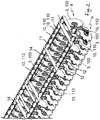
Fig. 2 shows a partially enlarged perspective view of a part of the agricultural machine. -
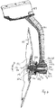
Fig. 3 shows a first embodiment of the implement regulation device according tofig. 1 in section. -
Fig. 4 shows a partially enlarged perspective view of a hub portion of an arm of the embodiment according tofig. 3 , which hub portion consists of a part of the implement regulation device according to the invention. -
Fig. 5 shows a partially enlarged perspective view of a shaft which is attached to the hub portion of the disc, which constitutes a part of the first embodiment of the implement regulation device according to the invention. -
Fig. 6 shows a second embodiment of the implement regulation device according tofig. 1 in section. -
Fig. 7 shows a partially enlarged perspective view of a hub portion of an arm of the second embodiment according tofig. 6 , which hub portion constitutes a part of the implement regulation device according to the invention. -
Fig. 8 shows a partially enlarged perspective view of a shaft which is connected to the hub portion of the disc, which portion constitutes a part of the second embodiment of the implement regulation device according to the invention. -
Fig. 9 shows a shaft according tofig. 8 in a more perspective view than infig. 8 . - In
figs. 1 and2 an agricultural machine 1 is shown in a working position. The agricultural machine 1 has a frame 2 and a towing device 2a, which suitably is connectable to and can be towed by a not shown tractor. The machine 1 consists here of three rows a, b, c of implements in form of two former rows a, b of soil working, free rotatable, discs 3 and a rear row c with roller aggregates 4. Each disc 3 in one of the both rows a, b is turned to the opposite direction in comparison with corresponding discs in the second row b and a, respectively. As the discs 3 are provided infigs. 1 and2 in the row a an oil flow is given outwardly from the implement centre and in the row b a soil flow inwardly towards the implement centre. In a known way the rows a and b with discs 3 and rear row c with the roller aggregates 4 are divided in three individually hingedsections 5, 6 and 7. The transport wheels 8, which are journaled on theouter frame sections 5 and 7 are together with theframe sections 5, 7 by means of hydraulic power devices 9 turnable to a transport position for the agricultural machine 1. This principle construction of the implement is known. A first and a second embodiment of a method and an implement regulation device according to the invention provided on the implement of the agricultural machine 1 can also be used on other agricultural machines. - In
fig. 2 is shown more evident that discs 3 in the both rows a and b are freely journaled at the bottom of thearms transverse beams devices 13, 113 attached at the upper ends of thearms 10 by means of welding or moulding. Between thebeams protection metal sheets 14 are provided. - In
figs. 3-5 a first embodiment of the method according to the invention is shown in greater detail to change the adjustment of an implement and even a first embodiment of the implement regulation device to carry out the method. - In
fig. 3 is shown in greater enlargement the suspension and the bearing of the discs 3. Eachdisc 103 is accordingly fastened at thehub 20, which is freely journaled about a bearingportion 121b, which has the form of a substantially circularcylindrical part 21b of ashaft 21. The opposite end of theshaft 21 constitutes of aconical part 21a, which has the form of a substantially or partlyconical part 21a. The upper end of thearm 10 is provided with a bearing means 13, as a rubber spring or other flexible suspension. The bearing means 13 consists in a known way of two bearing halves, the lower bearing half being connected to the arm and the upper bearing half is by means of a screw/nut joint fastened at the lower bearing half. Thebeams 11 and 12 (seefig. 2 ) extent through the bearing means 13 and four rubber rods can in a known way be placed between thebeams hubs 20 by means of screw joints 22. Theshaft 21 is rotatable journaled in abearing 20a in thehub 20. Theshaft 21 is angled preferably a few degrees β according tofig. 3 between the centre axis of the substantiallyconical part 21a and the centre axis of the circularcylindrical part 21b which is placed in thebearing 20a. Theshaft 21 can be rotated and locked between at least two positions, so that an adjustable disc angle is achieved. Infig. 3 the angle between the substantiallyconical part 21a and the circularcylindrical part 21b of theshaft 21 is an angle β. As the substantiallyconical part 21a of the shaft is rotated for instance 180 degrees in a corresponding substantially or partly conical hole 24 in theend part 23 of thearm 10 to another position means that the disc angle in relation to the partlyconical part 21a can be amended to maximal 2β. In the shown case β can be about 2 degrees and 2β accordingly be about 4 degrees. Other wished position of theshaft 21 and the thereby values of the angle β are naturally also possible within the scope of the patent claims. - The circular
cylindrical part 21b of the bearing has on its towards the disc 3 faced side a protrudingpart 16 with a cut in 14 which extends in the circumferential direction and is provided at the circularcylindrical part 21b to receive a lockingdasher 15 to fasten theshaft 21 at the inner bearing half of thehub 20. - The
shaft 21 is in the circumferential direction provided with a pre-determined number ofchamfered surfaces 33 between theconical surfaces 34 of the partlyconical part 21a which together correspond to the form in the partly conical hole 24 in theend portion 23. The intended working angle is fixed by tightening a screw joint 30, as the chamfered surfaces meet correspondingly intended surfaces in theend part 23. Other configurations of the shaft form and the corresponding form of the hole are of course possible, as is described below. The outer form of the partlyconical part 21a of theshaft 21 shall correspond to the form of the receiving hole 24 in theend portion 23 of thearm 10, whereby a form tied and force tied coupling is achieved in at least two positions. The partlyconical part 21a can be formed, so that it comprise chamfered surfaces whish are preferably constantly distributed in the circumferential direction, preferably being of a constant number and preferably four in number. - The
shaft 21 consists also of another substantially or partlycylindrical part 21c between the partlyconical part 21a which can be introduced in thecylindrical end portion 23 of the arm and the circularcylindrical part 21b which exists in the bearing. Thispart 21c has in the circumferential direction distributedplain portions 35 to by means of a tool, as a not shown wrench, be able to rotate theconical part 21a of theshaft 21 in thecylindrical end portion 23 of the arm at the changing of the position of theshaft 21 and thereby also of the disc 3. - The centrally through a
hole 31 in the end portion fixedscrew 30 of the screw joint is screwed into a threadedhole 32 in theshaft 21. By loosening theshaft 21 in the partly conical hole 24 by partly screwing out the centrally in the shaft fixedscrew 30 the shaft can be rotated to a new intended position and fixed in this by tightening thescrew 30. Thereby is given a possibility to change a working angle of a disc 3. - The threaded part of the threaded
hole 32 should be so long, that by loosening thescrew 30 to rotate theshaft 21 to a new intended position, the screw is still engaged with said threaded part. At the outer end of theend portion 23 of thearm 10 thehole 31 in theend portion 23 is widened with acountersink 36 so that thehead 37 of thescrew 30 can be countersinked therein by tightening. The head of the screw is of a hexagon type, but can also be of another type, as a cap screw, a torq screw, a cross headed screw or a slotted screw. Instead of a screw the screw joint can consist of a threaded rod which extends out from thecoupling part 21a of theshaft 21, which rod can receive a nut which is tightened at the outer side of theend portion 23 by tightening the screw joint. - The
end portion 23 of thearm 10 has a preferably partly conical, towards the partlyconical part 21a formed corresponding with the chamfered provided hole 24. With a couple of easy handgrips the adjustment (rotating of the shaft 21) can be performed to a new position for the disc 3. - The
coupling part 21 a can be formed in a number of ways which make it possible to achieve a form tied and power tied coupling with theend portion 23 of thearm 10. The section of thecoupling part 21a should be uniformed with reduced section area seen from thebearing part 21b to make an easy adjustment possible. The section can accordingly be polygon formed. The receiving hole 24 has preferably a form which corresponds to the form of thecoupling part 21a. The form of the hole 24 needs however not identically correspond to the form of thecoupling part 21a, as long as the form tied and the power tied coupling between them can be achieved in a desired intended number of pre-determined positions. - In
figs. 6-9 a first embodiment of the method according to the invention is shown in greater detail to change the adjustment of an implement and even a first embodiment of the implement regulation device to carry out the method. - In
fig. 6 is shown in greater enlargement the suspension and the bearing of thediscs 103. Eachdisc 103 is accordingly fastened at thehub 120, which is freely journaled about a bearingportion 121b of a shaft 121, the bearingportion 121b having a substantially circular cylindrical form. The opposite end of the shaft 121 constitutes of acoupling part 121a, which has a substantially conical form. The upper end of anarm 110 is provided with a bearing means 113, as a rubber spring or other flexible suspension. The bearing means 113 consists in a known way of two bearing halves, the lower bearing half being connected to the arm and the upper bearing half is by means of a screw/nut joint fastened at the lower bearing half. Thebeams 11 and 12 (seefig. 2 ) extend through the bearing means 113 and four rubber rods can in a known way be placed between thebeams discs 103 are suitably screw tightened at thehubs 120 by means ofscrew joints 122 provided in the circumferential direction. - The shaft 121 is rotatably journaled in a
bearing 120a in thehub 120. The shaft 121 is angled preferably a few degrees β according tofig. 6 between the centre axis of the substantiallyconical part 121a and the centre axis of the circularcylindrical part 121b which is existing in thebearing 120a. The shaft 121 can be rotated and fixed between at least two positions, so that an adjustable disc angle is achieved. Infig. 6 the angle between the substantiallyconical part 121a and the circularcylindrical part 121b of the shaft 121 is an angle β. As the substantiallyconical part 121a of the shaft is rotated for instance 180 degrees in a corresponding substantially or partlyconical hole 124 in theend part 123 of thearm 110 to another position means that the disc angle in relation to the partlyconical part 121a can be amended to maximal 2β. In the shown case β can be about 2 degrees and 2β accordingly be about 4 degrees. Other wished position of the shaft 121 and thereby values of the angle β are naturally also possible within the scope of the patent claims. - The circular
cylindrical part 121b of the bearing has on its towards thedisc 103 faced side a protruding threadedpart 114 to receive anut 115 to fasten the shaft 121 at the inner bearing half of thehub 120. - The shaft 121 also consists of another substantially
cylindrical part 121c between theconical part 121a which can be introduced in thecylindrical end portion 123 of the arm and the circularcylindrical part 121b which exists in the bearing. Thispart 121c has in the circumferential direction distributedplain parts 135 to by means of a tool, as a not shown wrench, can rotate the shaft 121 theconical part 121a of the shaft 121 in thecylindrical end portion 123 of the arm at the changing of the position of the shaft 121 and thereby also of thedisc 103. - The centrally through a
hole 131 in the end portion fixed screw 130 of the screw joint is screwed into a threadedhole 132 in the conical part of the shaft 121. By loosening the shaft 121 in theconical hole 124 by partly screwing out the centrally in the shaft fixed screw 130 the shaft can be rotated to a new intended position and fixed in this by tightening the screw 130. Thereby is given a possibility to change a working angle of adisc 103. - The threaded part of the threaded
hole 132 should be so long, that by loosening the screw 130 to rotate the shaft 121 to a new intended position, the screw 130 is still engaged with said threaded part. At the outer end of theend portion 123 of thearm 110 thehole 131 in theend portion 123 is widened with acountersink 136 so that the head 137 of the screw 130 can be countersinked therein. The head 137 of the screw 130 is of a hexagon type, but can also be of another type, as a cap screw, a torq screw, a cross headed screw or a slotted screw. Instead of a screw the screw joint can consist of a threaded rod which protrudes out from thecouplings part 121a of the shaft 121, which rod can receive a nut which is tightened at the outer side of theend portion 123 by tightening the screw joint. - The
end portion 123 of thearm 110 has a preferably conical, towards the partlyconical part 121aform corresponding hole 124. With a couple of easy handgrips the adjustment (rotating of the shaft 121) can be performed to a new position for thedisc 103. - At the end of the
part 123 is provided an area with a profiled, roundabout extendedpart 142, which is faced against the opening of the hole in the axial direction towards the conical end of the shaft 121 and which form a symmetrical form with frequent parts. At the transition between theconical part 121a and themid part 121c on the shaft 121 is also provided an area with a profiled, roundabout extendedpart 142, which is faced against the opening of the hole in the axial direction towards the conical end of the shaft 121 and which form symmetrically frequent symmetrical positions to fit to the form of the profiledroundabout part 142. As theconical end part 121a of the shaft 121 is led in with its conical point into theconical hole 124 of theend part 123 and the screw 130 is tightened the profiledparts disc 103 in relation to thearm 110, which has been described above in connection with the angle β. - Between the point of the
conical part 121a and the bottom of theconical hole 124 is a space arranged to provide intended clamp action between the profiledparts parts conical part 121a of the shaft 121 at least two distinct positions in theconical hole 124. By tightening the screw 130 form tied and force tied coupling between theend portion 123 of thearm 110 and the shaft 121 is possible. The section of theconical part 121c of the shaft 121 should therefore have a circular form to easy adjustment to intended positions. - On the side of the shaft a cut can be provided and
markings 145 can be provided on themid part 121c of the shaft for visual marking of the different positions of theconical part 121a of the shaft 121 in relation to thehole 124. The form of the hole does not be identically correspond to the form of thecoupling part 121a as long as a form tied and force tied coupling can be achieved between them in intended pre-determined positions. - The method and the implement regulation device according to the invention is to its construction not limited to the embodiments shown in
figs. 1-9 , but can be modified within the scope of the accompanying claims.
Claims (11)
- Implement regulation method for an agricultural machine (1) comprising a frame (2), at least a with the frame connected, in the driving direction transferred row (a, b) of implements (3) in the form of journaled discs (3), which are freely rotatable, each disc (3) being connected to an arm (10, 110), which is journaled at the frame (2) and to which each disc is connected via a shaft (21, 121) attached to the hub of the disc, wherein the hub (20, 120) of each disc (3, 103) is provided with a bearing part (21b, 121b) for the shaft (21, 121), which bearing part is journaled at the middle of the hub, and wherein the shaft at its other end has a coupling part (21a, 121a) formed so that it substantially corresponds to a form part at an end portion (23, 123) of the arm (10, 110), whereby a form tied and force tied coupling is achieved, characterised in that the centre axis of the coupling part (21a, 121a) is angled at an angle (β) in relation to the centre axis of the bearing part (21b, 121b), and that the form tied and force tied coupling can be achieved in at least two pre-determined positions freely receiving said coupling part in a corresponding hole (24, 124) in the end portion (23, 123) of the arm (10, 110), wherein the method comprises changing a working angle of an implement (3) by loosening the shaft in the receiving hole (24, 124) by loosening a screw joint (30, 130), so that the coupling part (21a, 121a) of the shaft is loosened, rotating in the end portion to a new intended position, and fixedly locking it in this position by tightening said screw joint.
- Method according to claim 1, characterised in that it further comprises fixing said working angle by tightening said screw joint by leading a cut screw (30, 130) through a central hole (31, 131) in the end portion (23, 123) of the arm (10, 110) and screw tightening it in a threaded hole (32, 132) in the shaft (21, 121).
- Method according to claim 2, characterised in that it further comprises screw tightening said screw head of said screw (30, 130) so that it abuts a step in a recess (36, 136) in the end portion (23, 123) with said central hole (31, 131).
- Method according to any of claims 1-3, characterised in that the coupling part (21a) of the shaft (21) has a partially conical form and is provided in the circumferential direction with a pre-determined number of chamfered surfaces (33) between the conical surfaces (34) of the coupling part (21a), said surfaces substantially corresponding to the chamfered surfaces in the receiving hole (24), wherein the method further comprises fixing said working angle by tightening the screw (30) as the chamfered surfaces of the conical part (21a) of the shaft (21) meet correspondingly intended surfaces in a new position in the end portion (23).
- Method according to any of claim 1-3, characterised in that the substantially conical part (121a) of the shaft (121) is provided with a profiled roundabout extending part (142) which is faced in the axial direction against its end (138), and that the end portion (123) at the end of the hole (124) is provided with a corresponding a profiled roundabout extending part (143) which is faced in the axial direction against its opening, wherein the method further comprises tightening the profiled parts (142, 143) together by means of a screw joint (130) so that the profiled parts (142, 143) form a form tied and force tied coupling.
- Agricultural machine (1) comprising a frame (2), at least one with the frame connected, in the driving direction transferred row (a, b) of implements (3, 103) in the form of journaled discs (3, 103), which are freely rotatable, each disc (3, 103) being connected to an arm (10, 110), which is journaled at the frame (2) and to which each disc is connected via a shaft (21, 121) attached to the hub of the disc, wherein the hub (20, 120) of each disc (3, 103) has a bearing part (21b, 121b) for the shaft (21, 121), which bearing part is journaled at the middle of the hub, and wherein the shaft at its other end has a coupling part (21a, 121a) having a formed portion (33, 143), so that it corresponds to a formed portion (142) of the end portion (23,123) of the arm (10, 110), whereby a form tied and force tied coupling is achieved, characterised in that the centre axis of the coupling part (21a, 121a) is angled at an angle (β) in relation to the centre axis of the bearing part (21b, 121b), and that the form tied and force tied coupling can be achieved in at least two pre-determined positions, wherein the agricultural machine (1) further comprises an implement regulation device comprising a screw joint (30, 130), which is centrally provided and connects the coupling part (21a, 121a) of the shaft (21, 121) with the end portion (23, 123) of the arm (10, 110), and which is provided to be loosened so that the shaft can be turned to a new intended position by loosening of the shaft in a receiving hole, and be fixed locked in this position by tightening said screw joint, thereby giving the possibility to change a working angle of an implement (3, 103).
- Agricultural machine (1) according to claim 6, characterised in that said screw joint consists of a screw (30, 103) which is led through a central hole (31, 131) in the end portion (23, 123) of the arm (10, 110) and is provided to be screwed in a threaded hole (32, 132) in the coupling part (21a, 121a) of the shaft (21, 121).
- Agricultural machine (1) according to claim 7, characterised in that the threaded part of the threaded hole (32, 132) is long enough to still be engaged with said threaded part if the screw (30, 130) for rotating the coupling part (21a, 121a) of the shaft (21, 121) is loosened to a new intended position.
- Agricultural machine (1) according to claim 6-8, characterised in that the coupling part (21a) of the shaft (21) has a partially conical form and is provided in the circumferential direction with a pre-determined number of chamfered surfaces (33) between the conical surfaces (34) of the coupling part (21a), which surfaces substantially correspond to chamfered surfaces in the receiving hole (24), said working angle being fixed by tightening said screw (30), wherein the chamfered surfaces (33) form a form tied and power tied coupling when the parts have been brought together.
- Agricultural machine (1) according to any of claims 6-8, characterised in that the substantially conical part (121a) of the shaft (121) is provided with a profiled, roundabout extending part (142), which in the axel direction is faced against the point of the substantially conical part, and that the end portion (123) at the end of the substantially conical hole (124) is provided with a corresponding profiled, roundabout extending part (143), which is faced in the axel direction, said working angle being fixed by tightening the screw (130), wherein the profiled parts (142, 143) form a form tied and force tied coupling when the parts have been brought together.
- Agricultural machine (1) according to any of claims 4-9, characterised in that between the bearing part (21b, 121b) of the shaft (21, 121) and the coupling part (21a, 121a) of the shaft is provided a partially circular part (21c, 121c) with plain engagement surfaces to make it possible to rotate the shaft, for instance by means of a wrench.
Applications Claiming Priority (2)
| Application Number | Priority Date | Filing Date | Title |
|---|---|---|---|
| SE1450055A SE540109C2 (en) | 2014-01-21 | 2014-01-21 | Implement control device and method of implement control in an agricultural implement |
| PCT/SE2015/050056 WO2015112077A1 (en) | 2014-01-21 | 2015-01-21 | Method and implement regulation device for an agricultural machine |
Publications (3)
| Publication Number | Publication Date |
|---|---|
| EP3096597A1 EP3096597A1 (en) | 2016-11-30 |
| EP3096597A4 EP3096597A4 (en) | 2017-11-22 |
| EP3096597B1 true EP3096597B1 (en) | 2020-09-30 |
Family
ID=53681743
Family Applications (1)
| Application Number | Title | Priority Date | Filing Date |
|---|---|---|---|
| EP15740566.3A Active EP3096597B1 (en) | 2014-01-21 | 2015-01-21 | Method and implement regulation device for an agricultural machine |
Country Status (4)
| Country | Link |
|---|---|
| EP (1) | EP3096597B1 (en) |
| CA (1) | CA2934907C (en) |
| SE (1) | SE540109C2 (en) |
| WO (1) | WO2015112077A1 (en) |
Families Citing this family (2)
| Publication number | Priority date | Publication date | Assignee | Title |
|---|---|---|---|---|
| DE102018105125A1 (en) | 2018-03-06 | 2019-09-12 | Horsch Maschinen Gmbh | Agricultural tillage implement with depth adjustable work tools |
| AT17083U1 (en) * | 2019-06-19 | 2021-05-15 | Nke Austria Gmbh | Storage unit |
Family Cites Families (7)
| Publication number | Priority date | Publication date | Assignee | Title |
|---|---|---|---|---|
| US1042651A (en) | 1912-03-28 | 1912-10-29 | John H Davis | Disk plow. |
| US2244774A (en) * | 1940-03-11 | 1941-06-10 | Hewitt William John | Colter |
| US3244237A (en) * | 1964-06-03 | 1966-04-05 | Case Co J I | Means adjustably connecting an earth working disk to a standard |
| NL8902596A (en) * | 1989-10-19 | 1991-05-16 | Evers B V | APPARATUS FOR TILLING THE SOIL AND METHOD FOR USE THEREOF |
| SE518975C2 (en) | 2000-09-04 | 2002-12-10 | Vaederstad Verken Ab | Plate with center recess for a hub and agricultural machine with such plate |
| DE10104911A1 (en) * | 2001-02-03 | 2002-08-08 | Lemken Gmbh & Co Kg | Soil cultivating machine comprises rows of hollow disks rotating about vertical axes at a working angle adjustable about an ideal center of rotation located in the region of the lower third on the imaginary disk surface |
| US6913085B2 (en) * | 2003-05-14 | 2005-07-05 | Deere & Company | Single standard double disk configuration |
-
2014
- 2014-01-21 SE SE1450055A patent/SE540109C2/en unknown
-
2015
- 2015-01-21 CA CA2934907A patent/CA2934907C/en active Active
- 2015-01-21 WO PCT/SE2015/050056 patent/WO2015112077A1/en not_active Ceased
- 2015-01-21 EP EP15740566.3A patent/EP3096597B1/en active Active
Non-Patent Citations (1)
| Title |
|---|
| None * |
Also Published As
| Publication number | Publication date |
|---|---|
| WO2015112077A1 (en) | 2015-07-30 |
| CA2934907C (en) | 2022-10-18 |
| CA2934907A1 (en) | 2015-07-30 |
| EP3096597A4 (en) | 2017-11-22 |
| EP3096597A1 (en) | 2016-11-30 |
| SE540109C2 (en) | 2018-04-03 |
| SE1450055A1 (en) | 2015-07-22 |
Similar Documents
| Publication | Publication Date | Title |
|---|---|---|
| US7762345B2 (en) | Conservation tillage implement, system and method | |
| US20140262370A1 (en) | Universal custom agricultural field preparation implement | |
| US20110155401A1 (en) | Vertical Tine Tillage Tandem Frame And Inter-related Secondary Tillage, Planting and Fertilizing Machine | |
| US11330752B2 (en) | Variable angle disc hub for a tiller jump arm assembly | |
| CA2934907C (en) | Method and implement regulation device for an agricultural machine | |
| AU2013354842B2 (en) | Split axle, axle-hub unit and use thereof | |
| US11324152B2 (en) | Single bolt disc hub for a tiller jump arm assembly | |
| US12446481B2 (en) | Agricultural drill/planter/coulter/disc blade with step plane notch edge | |
| WO2014025308A1 (en) | Method and regulation device for an agricultural implement | |
| EP3972403B1 (en) | Agricultural disc blade with step plane notch edge | |
| US11317552B2 (en) | Triangular tiller jump arm mount | |
| US11317553B2 (en) | Tiller jump arm wearplate spacer | |
| RU2799085C2 (en) | Agricultural disk knife with a multi-diameter edge with flat grooves (variants) | |
| DE2943041A1 (en) | TILLAGE MACHINE | |
| EP2944172B1 (en) | Split axle, axle-hub unit and use thereof | |
| RU220873U1 (en) | ROTOR STAND FOR TILLAGE MILL WITH VERTICAL AXIS OF ROTATION | |
| US20260137016A1 (en) | Agricultural tillage implement and assemblies | |
| CN107624278B (en) | Rotary tillage cutter | |
| CA2854653A1 (en) | Universal custom agricultural field preparation implement |
Legal Events
| Date | Code | Title | Description |
|---|---|---|---|
| PUAI | Public reference made under article 153(3) epc to a published international application that has entered the european phase |
Free format text: ORIGINAL CODE: 0009012 |
|
| 17P | Request for examination filed |
Effective date: 20160817 |
|
| AK | Designated contracting states |
Kind code of ref document: A1 Designated state(s): AL AT BE BG CH CY CZ DE DK EE ES FI FR GB GR HR HU IE IS IT LI LT LU LV MC MK MT NL NO PL PT RO RS SE SI SK SM TR |
|
| AX | Request for extension of the european patent |
Extension state: BA ME |
|
| DAX | Request for extension of the european patent (deleted) | ||
| A4 | Supplementary search report drawn up and despatched |
Effective date: 20171024 |
|
| RIC1 | Information provided on ipc code assigned before grant |
Ipc: A01B 23/06 20060101ALI20171018BHEP Ipc: A01B 35/28 20060101AFI20171018BHEP Ipc: A01B 71/04 20060101ALI20171018BHEP |
|
| RAP1 | Party data changed (applicant data changed or rights of an application transferred) |
Owner name: VAEDERSTAD HOLDING AB |
|
| STAA | Information on the status of an ep patent application or granted ep patent |
Free format text: STATUS: EXAMINATION IS IN PROGRESS |
|
| 17Q | First examination report despatched |
Effective date: 20191025 |
|
| GRAP | Despatch of communication of intention to grant a patent |
Free format text: ORIGINAL CODE: EPIDOSNIGR1 |
|
| STAA | Information on the status of an ep patent application or granted ep patent |
Free format text: STATUS: GRANT OF PATENT IS INTENDED |
|
| INTG | Intention to grant announced |
Effective date: 20200514 |
|
| RIN1 | Information on inventor provided before grant (corrected) |
Inventor name: COLLIN, MORGAN Inventor name: GYLLENHAMMAR, PER Inventor name: EDVINSSON, MIKAEL Inventor name: LUBKOWITZ, ANDREAS |
|
| GRAS | Grant fee paid |
Free format text: ORIGINAL CODE: EPIDOSNIGR3 |
|
| GRAA | (expected) grant |
Free format text: ORIGINAL CODE: 0009210 |
|
| STAA | Information on the status of an ep patent application or granted ep patent |
Free format text: STATUS: THE PATENT HAS BEEN GRANTED |
|
| AK | Designated contracting states |
Kind code of ref document: B1 Designated state(s): AL AT BE BG CH CY CZ DE DK EE ES FI FR GB GR HR HU IE IS IT LI LT LU LV MC MK MT NL NO PL PT RO RS SE SI SK SM TR |
|
| REG | Reference to a national code |
Ref country code: GB Ref legal event code: FG4D Ref country code: CH Ref legal event code: EP |
|
| REG | Reference to a national code |
Ref country code: AT Ref legal event code: REF Ref document number: 1317782 Country of ref document: AT Kind code of ref document: T Effective date: 20201015 Ref country code: DE Ref legal event code: R096 Ref document number: 602015059810 Country of ref document: DE |
|
| REG | Reference to a national code |
Ref country code: IE Ref legal event code: FG4D |
|
| PG25 | Lapsed in a contracting state [announced via postgrant information from national office to epo] |
Ref country code: FI Free format text: LAPSE BECAUSE OF FAILURE TO SUBMIT A TRANSLATION OF THE DESCRIPTION OR TO PAY THE FEE WITHIN THE PRESCRIBED TIME-LIMIT Effective date: 20200930 Ref country code: GR Free format text: LAPSE BECAUSE OF FAILURE TO SUBMIT A TRANSLATION OF THE DESCRIPTION OR TO PAY THE FEE WITHIN THE PRESCRIBED TIME-LIMIT Effective date: 20201231 Ref country code: SE Free format text: LAPSE BECAUSE OF FAILURE TO SUBMIT A TRANSLATION OF THE DESCRIPTION OR TO PAY THE FEE WITHIN THE PRESCRIBED TIME-LIMIT Effective date: 20200930 Ref country code: HR Free format text: LAPSE BECAUSE OF FAILURE TO SUBMIT A TRANSLATION OF THE DESCRIPTION OR TO PAY THE FEE WITHIN THE PRESCRIBED TIME-LIMIT Effective date: 20200930 Ref country code: BG Free format text: LAPSE BECAUSE OF FAILURE TO SUBMIT A TRANSLATION OF THE DESCRIPTION OR TO PAY THE FEE WITHIN THE PRESCRIBED TIME-LIMIT Effective date: 20201230 Ref country code: NO Free format text: LAPSE BECAUSE OF FAILURE TO SUBMIT A TRANSLATION OF THE DESCRIPTION OR TO PAY THE FEE WITHIN THE PRESCRIBED TIME-LIMIT Effective date: 20201230 |
|
| REG | Reference to a national code |
Ref country code: AT Ref legal event code: MK05 Ref document number: 1317782 Country of ref document: AT Kind code of ref document: T Effective date: 20200930 |
|
| PG25 | Lapsed in a contracting state [announced via postgrant information from national office to epo] |
Ref country code: LV Free format text: LAPSE BECAUSE OF FAILURE TO SUBMIT A TRANSLATION OF THE DESCRIPTION OR TO PAY THE FEE WITHIN THE PRESCRIBED TIME-LIMIT Effective date: 20200930 Ref country code: RS Free format text: LAPSE BECAUSE OF FAILURE TO SUBMIT A TRANSLATION OF THE DESCRIPTION OR TO PAY THE FEE WITHIN THE PRESCRIBED TIME-LIMIT Effective date: 20200930 |
|
| REG | Reference to a national code |
Ref country code: NL Ref legal event code: MP Effective date: 20200930 |
|
| REG | Reference to a national code |
Ref country code: LT Ref legal event code: MG4D |
|
| PG25 | Lapsed in a contracting state [announced via postgrant information from national office to epo] |
Ref country code: RO Free format text: LAPSE BECAUSE OF FAILURE TO SUBMIT A TRANSLATION OF THE DESCRIPTION OR TO PAY THE FEE WITHIN THE PRESCRIBED TIME-LIMIT Effective date: 20200930 Ref country code: SM Free format text: LAPSE BECAUSE OF FAILURE TO SUBMIT A TRANSLATION OF THE DESCRIPTION OR TO PAY THE FEE WITHIN THE PRESCRIBED TIME-LIMIT Effective date: 20200930 Ref country code: PT Free format text: LAPSE BECAUSE OF FAILURE TO SUBMIT A TRANSLATION OF THE DESCRIPTION OR TO PAY THE FEE WITHIN THE PRESCRIBED TIME-LIMIT Effective date: 20210201 Ref country code: EE Free format text: LAPSE BECAUSE OF FAILURE TO SUBMIT A TRANSLATION OF THE DESCRIPTION OR TO PAY THE FEE WITHIN THE PRESCRIBED TIME-LIMIT Effective date: 20200930 Ref country code: NL Free format text: LAPSE BECAUSE OF FAILURE TO SUBMIT A TRANSLATION OF THE DESCRIPTION OR TO PAY THE FEE WITHIN THE PRESCRIBED TIME-LIMIT Effective date: 20200930 Ref country code: LT Free format text: LAPSE BECAUSE OF FAILURE TO SUBMIT A TRANSLATION OF THE DESCRIPTION OR TO PAY THE FEE WITHIN THE PRESCRIBED TIME-LIMIT Effective date: 20200930 |
|
| PG25 | Lapsed in a contracting state [announced via postgrant information from national office to epo] |
Ref country code: IS Free format text: LAPSE BECAUSE OF FAILURE TO SUBMIT A TRANSLATION OF THE DESCRIPTION OR TO PAY THE FEE WITHIN THE PRESCRIBED TIME-LIMIT Effective date: 20210130 Ref country code: PL Free format text: LAPSE BECAUSE OF FAILURE TO SUBMIT A TRANSLATION OF THE DESCRIPTION OR TO PAY THE FEE WITHIN THE PRESCRIBED TIME-LIMIT Effective date: 20200930 Ref country code: AL Free format text: LAPSE BECAUSE OF FAILURE TO SUBMIT A TRANSLATION OF THE DESCRIPTION OR TO PAY THE FEE WITHIN THE PRESCRIBED TIME-LIMIT Effective date: 20200930 Ref country code: AT Free format text: LAPSE BECAUSE OF FAILURE TO SUBMIT A TRANSLATION OF THE DESCRIPTION OR TO PAY THE FEE WITHIN THE PRESCRIBED TIME-LIMIT Effective date: 20200930 Ref country code: ES Free format text: LAPSE BECAUSE OF FAILURE TO SUBMIT A TRANSLATION OF THE DESCRIPTION OR TO PAY THE FEE WITHIN THE PRESCRIBED TIME-LIMIT Effective date: 20200930 |
|
| PG25 | Lapsed in a contracting state [announced via postgrant information from national office to epo] |
Ref country code: SK Free format text: LAPSE BECAUSE OF FAILURE TO SUBMIT A TRANSLATION OF THE DESCRIPTION OR TO PAY THE FEE WITHIN THE PRESCRIBED TIME-LIMIT Effective date: 20200930 |
|
| REG | Reference to a national code |
Ref country code: DE Ref legal event code: R097 Ref document number: 602015059810 Country of ref document: DE |
|
| PLBE | No opposition filed within time limit |
Free format text: ORIGINAL CODE: 0009261 |
|
| STAA | Information on the status of an ep patent application or granted ep patent |
Free format text: STATUS: NO OPPOSITION FILED WITHIN TIME LIMIT |
|
| PG25 | Lapsed in a contracting state [announced via postgrant information from national office to epo] |
Ref country code: DK Free format text: LAPSE BECAUSE OF FAILURE TO SUBMIT A TRANSLATION OF THE DESCRIPTION OR TO PAY THE FEE WITHIN THE PRESCRIBED TIME-LIMIT Effective date: 20200930 Ref country code: MC Free format text: LAPSE BECAUSE OF FAILURE TO SUBMIT A TRANSLATION OF THE DESCRIPTION OR TO PAY THE FEE WITHIN THE PRESCRIBED TIME-LIMIT Effective date: 20200930 |
|
| REG | Reference to a national code |
Ref country code: CH Ref legal event code: PL |
|
| 26N | No opposition filed |
Effective date: 20210701 |
|
| PG25 | Lapsed in a contracting state [announced via postgrant information from national office to epo] |
Ref country code: LU Free format text: LAPSE BECAUSE OF NON-PAYMENT OF DUE FEES Effective date: 20210121 |
|
| REG | Reference to a national code |
Ref country code: BE Ref legal event code: MM Effective date: 20210131 |
|
| PG25 | Lapsed in a contracting state [announced via postgrant information from national office to epo] |
Ref country code: IT Free format text: LAPSE BECAUSE OF FAILURE TO SUBMIT A TRANSLATION OF THE DESCRIPTION OR TO PAY THE FEE WITHIN THE PRESCRIBED TIME-LIMIT Effective date: 20200930 |
|
| PG25 | Lapsed in a contracting state [announced via postgrant information from national office to epo] |
Ref country code: SI Free format text: LAPSE BECAUSE OF FAILURE TO SUBMIT A TRANSLATION OF THE DESCRIPTION OR TO PAY THE FEE WITHIN THE PRESCRIBED TIME-LIMIT Effective date: 20200930 Ref country code: CH Free format text: LAPSE BECAUSE OF NON-PAYMENT OF DUE FEES Effective date: 20210131 Ref country code: LI Free format text: LAPSE BECAUSE OF NON-PAYMENT OF DUE FEES Effective date: 20210131 |
|
| PG25 | Lapsed in a contracting state [announced via postgrant information from national office to epo] |
Ref country code: IE Free format text: LAPSE BECAUSE OF NON-PAYMENT OF DUE FEES Effective date: 20210121 |
|
| PG25 | Lapsed in a contracting state [announced via postgrant information from national office to epo] |
Ref country code: IS Free format text: LAPSE BECAUSE OF FAILURE TO SUBMIT A TRANSLATION OF THE DESCRIPTION OR TO PAY THE FEE WITHIN THE PRESCRIBED TIME-LIMIT Effective date: 20210130 |
|
| PG25 | Lapsed in a contracting state [announced via postgrant information from national office to epo] |
Ref country code: BE Free format text: LAPSE BECAUSE OF NON-PAYMENT OF DUE FEES Effective date: 20210131 |
|
| PG25 | Lapsed in a contracting state [announced via postgrant information from national office to epo] |
Ref country code: HU Free format text: LAPSE BECAUSE OF FAILURE TO SUBMIT A TRANSLATION OF THE DESCRIPTION OR TO PAY THE FEE WITHIN THE PRESCRIBED TIME-LIMIT; INVALID AB INITIO Effective date: 20150121 |
|
| PG25 | Lapsed in a contracting state [announced via postgrant information from national office to epo] |
Ref country code: CY Free format text: LAPSE BECAUSE OF FAILURE TO SUBMIT A TRANSLATION OF THE DESCRIPTION OR TO PAY THE FEE WITHIN THE PRESCRIBED TIME-LIMIT Effective date: 20200930 |
|
| PG25 | Lapsed in a contracting state [announced via postgrant information from national office to epo] |
Ref country code: MK Free format text: LAPSE BECAUSE OF FAILURE TO SUBMIT A TRANSLATION OF THE DESCRIPTION OR TO PAY THE FEE WITHIN THE PRESCRIBED TIME-LIMIT Effective date: 20200930 |
|
| PG25 | Lapsed in a contracting state [announced via postgrant information from national office to epo] |
Ref country code: MT Free format text: LAPSE BECAUSE OF FAILURE TO SUBMIT A TRANSLATION OF THE DESCRIPTION OR TO PAY THE FEE WITHIN THE PRESCRIBED TIME-LIMIT Effective date: 20200930 |
|
| PG25 | Lapsed in a contracting state [announced via postgrant information from national office to epo] |
Ref country code: TR Free format text: LAPSE BECAUSE OF FAILURE TO SUBMIT A TRANSLATION OF THE DESCRIPTION OR TO PAY THE FEE WITHIN THE PRESCRIBED TIME-LIMIT Effective date: 20200930 |
|
| PGFP | Annual fee paid to national office [announced via postgrant information from national office to epo] |
Ref country code: GB Payment date: 20251204 Year of fee payment: 12 |
|
| PGFP | Annual fee paid to national office [announced via postgrant information from national office to epo] |
Ref country code: FR Payment date: 20251222 Year of fee payment: 12 |
|
| PGFP | Annual fee paid to national office [announced via postgrant information from national office to epo] |
Ref country code: CZ Payment date: 20251229 Year of fee payment: 12 |
|
| PGFP | Annual fee paid to national office [announced via postgrant information from national office to epo] |
Ref country code: DE Payment date: 20251203 Year of fee payment: 12 |