EP3096457A1 - Proximity sensor - Google Patents
Proximity sensor Download PDFInfo
- Publication number
- EP3096457A1 EP3096457A1 EP16170295.6A EP16170295A EP3096457A1 EP 3096457 A1 EP3096457 A1 EP 3096457A1 EP 16170295 A EP16170295 A EP 16170295A EP 3096457 A1 EP3096457 A1 EP 3096457A1
- Authority
- EP
- European Patent Office
- Prior art keywords
- tank circuit
- active
- resonant tank
- passive
- circuit
- Prior art date
- Legal status (The legal status is an assumption and is not a legal conclusion. Google has not performed a legal analysis and makes no representation as to the accuracy of the status listed.)
- Granted
Links
- 230000004044 response Effects 0.000 claims abstract description 95
- 230000008878 coupling Effects 0.000 claims abstract description 71
- 238000010168 coupling process Methods 0.000 claims abstract description 71
- 238000005859 coupling reaction Methods 0.000 claims abstract description 71
- 238000005259 measurement Methods 0.000 claims abstract description 46
- 239000003990 capacitor Substances 0.000 claims abstract description 28
- 230000005291 magnetic effect Effects 0.000 claims abstract description 26
- 230000005284 excitation Effects 0.000 claims abstract description 16
- 238000006073 displacement reaction Methods 0.000 claims abstract description 9
- 238000000034 method Methods 0.000 claims description 9
- 230000001419 dependent effect Effects 0.000 description 8
- 230000002596 correlated effect Effects 0.000 description 5
- 238000001514 detection method Methods 0.000 description 5
- 230000005294 ferromagnetic effect Effects 0.000 description 4
- 238000000926 separation method Methods 0.000 description 4
- 238000013037 co-molding Methods 0.000 description 3
- 238000003466 welding Methods 0.000 description 3
- 230000001276 controlling effect Effects 0.000 description 2
- 238000013461 design Methods 0.000 description 2
- 230000008901 benefit Effects 0.000 description 1
- 239000003985 ceramic capacitor Substances 0.000 description 1
- 230000008859 change Effects 0.000 description 1
- 230000003750 conditioning effect Effects 0.000 description 1
- 230000000875 corresponding effect Effects 0.000 description 1
- 230000007423 decrease Effects 0.000 description 1
- 230000000694 effects Effects 0.000 description 1
- 230000003116 impacting effect Effects 0.000 description 1
- 230000003993 interaction Effects 0.000 description 1
- 239000000463 material Substances 0.000 description 1
- 238000012986 modification Methods 0.000 description 1
- 230000004048 modification Effects 0.000 description 1
- 230000003287 optical effect Effects 0.000 description 1
- 230000010355 oscillation Effects 0.000 description 1
- 230000003071 parasitic effect Effects 0.000 description 1
- 230000008569 process Effects 0.000 description 1
- 238000010561 standard procedure Methods 0.000 description 1
Images


Classifications
-
- G—PHYSICS
- G01—MEASURING; TESTING
- G01D—MEASURING NOT SPECIALLY ADAPTED FOR A SPECIFIC VARIABLE; ARRANGEMENTS FOR MEASURING TWO OR MORE VARIABLES NOT COVERED IN A SINGLE OTHER SUBCLASS; TARIFF METERING APPARATUS; MEASURING OR TESTING NOT OTHERWISE PROVIDED FOR
- G01D5/00—Mechanical means for transferring the output of a sensing member; Means for converting the output of a sensing member to another variable where the form or nature of the sensing member does not constrain the means for converting; Transducers not specially adapted for a specific variable
- G01D5/12—Mechanical means for transferring the output of a sensing member; Means for converting the output of a sensing member to another variable where the form or nature of the sensing member does not constrain the means for converting; Transducers not specially adapted for a specific variable using electric or magnetic means
- G01D5/14—Mechanical means for transferring the output of a sensing member; Means for converting the output of a sensing member to another variable where the form or nature of the sensing member does not constrain the means for converting; Transducers not specially adapted for a specific variable using electric or magnetic means influencing the magnitude of a current or voltage
- G01D5/20—Mechanical means for transferring the output of a sensing member; Means for converting the output of a sensing member to another variable where the form or nature of the sensing member does not constrain the means for converting; Transducers not specially adapted for a specific variable using electric or magnetic means influencing the magnitude of a current or voltage by varying inductance, e.g. by a movable armature
-
- G—PHYSICS
- G01—MEASURING; TESTING
- G01B—MEASURING LENGTH, THICKNESS OR SIMILAR LINEAR DIMENSIONS; MEASURING ANGLES; MEASURING AREAS; MEASURING IRREGULARITIES OF SURFACES OR CONTOURS
- G01B7/00—Measuring arrangements characterised by the use of electric or magnetic techniques
- G01B7/14—Measuring arrangements characterised by the use of electric or magnetic techniques for measuring distance or clearance between spaced objects or spaced apertures
-
- G—PHYSICS
- G01—MEASURING; TESTING
- G01B—MEASURING LENGTH, THICKNESS OR SIMILAR LINEAR DIMENSIONS; MEASURING ANGLES; MEASURING AREAS; MEASURING IRREGULARITIES OF SURFACES OR CONTOURS
- G01B7/00—Measuring arrangements characterised by the use of electric or magnetic techniques
-
- H—ELECTRICITY
- H03—ELECTRONIC CIRCUITRY
- H03K—PULSE TECHNIQUE
- H03K17/00—Electronic switching or gating, i.e. not by contact-making and –breaking
- H03K17/94—Electronic switching or gating, i.e. not by contact-making and –breaking characterised by the way in which the control signals are generated
- H03K17/945—Proximity switches
- H03K17/95—Proximity switches using a magnetic detector
- H03K17/952—Proximity switches using a magnetic detector using inductive coils
- H03K17/9537—Proximity switches using a magnetic detector using inductive coils in a resonant circuit
- H03K17/954—Proximity switches using a magnetic detector using inductive coils in a resonant circuit controlled by an oscillatory signal
Definitions
- Proximity sensing devices are devices that produce an output based upon a distance between two or more sensors or objects.
- Proximity sensors typically contain electrical circuits having an electrical, mechanical, or optical distance sensing portion.
- Electromechanical sensors are often used to establish contact between two objects, such as an end switch, and electrical sensors are frequently used when a distance measurement is desired.
- Electrical proximity sensors commonly include inductance sensors, which rely on unique electrical properties of inductance circuits to detect the proximity of a target object.
- Proximity sensors are prevalent in several industries, such as process management, automotive, and aviation. Their applications span a large range from traffic control to linkage actuation control. For example, proximity sensing devices are an integral and indispensable component of a modem aircraft. Knowledge that a moving surface has reached a particular location in its travel can promote proper and safe operation of various aircraft systems.
- a proximity sensor includes an active sensor, a passive target, and a measurement circuit.
- the active sensor includes an active resonant tank circuit that includes an excitation source, a first capacitor, and a first inductor.
- the passive target includes a passive resonant tank circuit that includes a second capacitor and a second inductor, where magnetic coupling between the first inductor and the second inductor varies as a function of physical displacement of the first inductor and the second inductor with respect to one another.
- the measurement circuit is configured to measure a coupled resonant frequency response in the active resonant tank circuit and provide a measured distance output based on the coupled resonant frequency response.
- a proximity sensor system in another embodiment, includes a proximity sensor and a controller.
- the proximity sensor includes an active sensor, a passive target, and a measurement circuit.
- the active sensor includes an active resonant tank circuit that includes an excitation source, a first capacitor, and a first inductor.
- the passive target includes a passive resonant tank circuit that includes a second capacitor and a second inductor, where magnetic coupling between the first inductor and the second inductor varies as a function of physical displacement of the first inductor and the second inductor with respect to one another.
- the measurement circuit is configured to measure a coupled resonant frequency response in the active resonant tank circuit and provide a measured distance output based on the coupled resonant frequency response.
- the controller is connected to the measurement circuit for controlling a system component based on the measured distance output.
- a method of sensing proximity includes powering an active sensor, measuring a coupled resonant frequency response, and producing a measured distance output based on the electrical response.
- the active sensor is powered, which includes an active resonant tank circuit, and is magnetically coupled to a passive resonant tank circuit of a passive target.
- the magnetic coupling between the active resonant tank circuit and the passive resonant tank circuit varies as a function of physical displacement between the active and passive resonant tank circuits with respect to one another.
- a coupled resonant frequency response is measured in the active circuit that is a function of the magnetic coupling between the active resonant tank circuit and the passive resonant tank circuit.
- a measured distance output is produced based on the coupled resonant frequency response.
- FIG. 1 is a schematic view of proximity sensor system 10, which includes active sensor 12, passive target 14, controller 16, first structure 18, second structure 20, and system components 22.
- Active sensor 12 includes measurement circuit 24 and active resonant tank circuit 26.
- Active resonant tank circuit 26 includes capacitor 28, inductor 30, and excitation source 32.
- Passive target 14 includes passive resonant tank circuit 34, which includes inductor 36 and capacitor 38. Also shown in FIG. 1 are distance d, capacitance C 1 , capacitance C 2 , inductance L 1 , Inductance L 2 , drive signal voltage V s , sensor output voltage V o , and magnetic field B.
- Active sensor 12 is physically connected to first structure 18 by welding, riveting, screwing, co-molding, or another fastening means. Also, active sensor 12 can be enclosed by a housing (not shown) which can then be attached to first structure 18. Similarly, passive target 14 is physically connected to second structure 20 by welding, riveting, screwing, co-molding, or another fastening means. Also, passive target 14 can be enclosed by a housing (not shown) which can then be attached to second structure 20. Active sensor 12 and passive target 14 are fixed to first structure 18 and second structure 20, respectively. However, active sensor 12 and passive target 14 can move relative to one another, as first structure 18 and second structure 20 can move with respect to each other. Distance d represents the physical distance between inductor 30 and inductor 36.
- inductor 30 is a component of active sensor 12, which is attached to first structure 18, distance d between inductors 30 and 36 can be easily correlated to other distances, such as a distance between active sensor 12 and passive target 14, and their respective components.
- first structure 18 and second structure 20 can be connected to each other but still free to move relative to each other, for example as parts of a linkage assembly.
- Measurement circuit 24 can be physically attached to first structure 18 by welding, riveting, screwing, co-molding, or another fastening means. Additionally, measurement 24 can be on a common printed circuit board with active sensor 12 or can otherwise be integrated into active sensor 12. For example, measurement circuit 24 and active resonant tank circuit 26 can be within a common housing within active sensor 12. Controller 16 can be mounted to first structure 18 or second structure 20; however, in many examples controller 16 can be mounted physically remotely from first structure 18 and second structure 20.
- Capacitor 28 of active resonant tank circuit 26 is electrically connected in series with inductor 30 and excitation source 32.
- Capacitor 28 has a capacitance C 1
- inductor 30 has an inductance L 1 .
- Excitation source 32 produces a drive signal voltage V s .
- Capacitor 38 of passive resonant tank circuit 34 is connected with inductor 36 in parallel.
- Capacitor 38 has a capacitance C 2
- inductor 36 has an inductance L 2 .
- Capacitors 28 and 38 can be a ceramic capacitor, film capacitor, or any type of capacitor capable of storing electrical energy and having sufficient quality factor Q to operate effectively in a resonant circuit.
- Inductors 30 and 36 can be a ferromagnetic inductor, an air core inductor, or any other type of inductor having sufficient quality factor Q to operate effectively in a resonant circuit.
- Excitation source 32 can be an alternating current (AC) power supply for producing a current or excitation pulse.
- AC alternating current
- Active resonant tank circuit 26 and its components create an active series resonator circuit, also known as a tank circuit, resonant circuit, or tuned circuit.
- Passive resonant tank circuit 34 and its components create a passive parallel resonator circuit, also known as a tank circuit, resonant circuit, or tuned circuit.
- Measurement circuit 24 is connected to active resonant tank circuit 26 across capacitor 28. Measurement circuit 24 measures sensor output voltage V o . Measurement circuit 24 is also electrically connected to controller 16, which further electrically connects to system components 22.
- System components 22 can be any system component capable of being moved or articulated. For example, first structure 18 and second structure 20 could be system components 22.
- excitation source 32 sends a current to capacitor 28, which stores charge and ultimately discharges the current to inductor 30.
- Excitation source 32 provides continuous power to active resonant tank circuit 26 creating continuous oscillations of magnetic field B at the natural frequency of active resonant tank circuit 26, creating resonance.
- Passive resonant tank circuit 34 is tuned to the same or similar resonant frequency of active circuit 32, where the product of capacitor 28 and inductor 30 can be approximately equal to the product of capacitor 38 and inductor 36.
- passive resonant tank circuit 34 When passive resonant tank circuit 34 is within range of magnetic field B , passive resonant tank circuit 34 and active resonant tank circuit 26 become magnetically coupled. When coupled, magnetic field B will induce a current through inductor 36, which will flow in passive resonant tank circuit 34. In response to this current flow, Lenz's law dictates that inductor 36 will produce a magnetic field in a direction opposite of that created by inductor 30. The magnetic field response by inductor 36 is received by inductor 30 of active resonant tank circuit 26. The reflected load can create a coupled resonant frequency response ⁇ c1 , or an electrical response, in active resonant tank circuit 26.
- the electrical response in active resonant tank circuit 26 is detectible by measuring and analyzing the current through or the voltage across a component of active resonant tank circuit 26.
- measurement circuit 24 measures the voltage across capacitor 28 to observe coupled resonant frequency responses ⁇ c1 and ⁇ c2 through active resonant tank circuit 26.
- measurement circuit 24 can measure the voltage across any component of active resonant tank circuit 26.
- Measurement circuit 24 can include an oscillator, demodulator, and other components to obtain an accurate measurement of coupled resonant frequency responses, ⁇ c1 and ⁇ c2 .
- a unique, easily detectible response can be observed through a measurement of coupled resonant frequency response ⁇ c1 ; however, for the response to be unique, easily detectible, and useful as a proximity sensor, some conditions can be met.
- the first condition is that a circuit quality factor Q is greater than 1 for both circuits, or: Q 1 > 1 and Q 2 > 1
- Q 1 is the quality factor of active resonant tank circuit 26 and Q 2 is the quality factor of passive resonant tank circuit 34.
- quality factors Q 1 and Q 2 are much greater than one (in many embodiments, at least one order of magnitude, i.e. ten times greater), or: Q 1 > > 1 and Q 2 > > 1
- R 1 is the resistance of active resonant tank circuit 26.
- Q 2 R 2 * C 2 L 2
- R 2 is the resistance of passive resonant tank circuit 34.
- R 1 and R 2 can be only the parasitic resistance of their respective circuit, because the circuit contains no added resistor component, as it is desired to maintain a high quality factor in each circuit.
- a second condition that can be met is that resonant frequencies or both circuits ⁇ R1 and of ⁇ R2 can be approximately equal.
- the third condition that can be met is that a coefficient of coupling k between active resonant tank circuit 26 and passive resonant tank circuit 34 can be greater than a critical coefficient of coupling k c between active resonant tank circuit 26 and passive resonant tank circuit 34.
- M is the mutual inductance of inductors L 1 and L 2 or inductors 30 and 36.
- the mutual inductance M of inductors 30 and 36 correlates directly and varies with distance d.
- the coupled resonant frequency responses, ⁇ c1 and ⁇ c2 of active resonant tank circuit 26 and passive resonant tank circuit 34, respectively, are dependent only on the uncoupled resonant frequencies ⁇ R1 and ⁇ R2 , respectively, and the coefficient of coupling k between active resonant tank circuit 26 and passive resonant tank circuit 34. Because the uncoupled resonant frequency will be fixed by the inductance L and capacitance C of each circuit, the coupled resonant frequency responses, ⁇ c1 and ⁇ c2 are primarily dependent on the coefficient of coupling k.
- the coupled resonant frequency response ⁇ c1 of active resonant tank circuit 26 is primarily dependent on the coefficient of coupling k between active resonant tank circuit 26 and passive resonant tank circuit 34.
- the coefficient of coupling k between active resonant tank circuit 26 and passive resonant tank circuit 34 is given by Equation 5 above, where M is the mutual inductance of inductors L 1 and L 2 or inductors 30 and 36.
- the mutual inductance M of inductors 30 and 36 is primarily dependent on distance d , the distance between inductors 30 and 36.
- the coefficient of coupling k is primarily dependent on distance d, and that the coupled resonant frequency responses ⁇ c1 and ⁇ c2 are then primarily dependent on distance d . Therefore, with active resonant tank circuit 26 and passive resonant tank circuit 34 meeting the exemplary conditions, the electrical response, or the coupled resonant frequency response ⁇ c1 , in active resonant tank circuit 26 caused by an interaction with passive resonant tank circuit 34 becomes a function primarily dependent on distance d between inductors 30 and 36.
- the coupled resonant frequency response ⁇ c1 can be measured by measurement circuit 24 and transformed into a measured distance output to be used by, for example, controller 16.
- active resonant tank circuit 26 and passive resonant tank circuit 34 to be used to sense proximity or distance.
- the electrical response can be correlated to the separation in distance d between active sensor 12 and passive target 14.
- Distance d represents the physical distance between inductor 30 and inductor 36. Because inductor is a component of active sensor 12 and inductor 36 is a component of first structure 18, distance d between inductors 30 and 36 can be easily correlated to other distances between active sensor 12 and first structure 18, and their respective components.
- the prior art includes proximity sensors that can include an active tank circuit of an active sensor and a ferromagnetic passive target. While a ferromagnetic target does produce an electrical response in the active circuit by affecting the magnetic field of the tank circuit's inductor, the application has some drawbacks. First, these sensors can have a small physical operating range, or struggle to operate over a large distance d. This imposes tight calibration requirements to allow the desired signal to be detected by the active sensor. Therefore, the electronic signature produced by this type of system can, in some examples, vary by only a few percent between a near condition (when the target is very close to the active sensor) and the far condition (when the target is relatively distant from the active sensor).
- the active sensor is designed to interact with ferromagnetic passive targets impacting the magnetic field of the active circuit
- the circuit is susceptible to ambient noise and interference. To account for such interference, can require a complicated design of the signal conditioning and measurement electronics interacting with the active portion of the sensor. This can increase the cost and complexity of the devices.
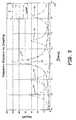
- FIG. 2 is a graph illustrating one embodiment of frequency response versus the coefficient of coupling k of active resonant tank circuit 26 and passive resonant tank circuit 34 FIG. 1 .
- Frequency ⁇ is displayed on the x-axis of the graph and magnitude Mag is displayed on the y-axis of the graph.
- magnitude Mag is displayed on the y-axis of the graph.
- Also displayed on the graph are four response curves, curve 40, curve 42, curve 44, and curve 46.
- Magnitude Mag has a range on the y-axis of 0 decibels (dB) to magnitude Mag of 140 dB, with intermediate markers along the y-axis denoting steps of 20 dB.
- Frequency ⁇ moves from the left to the right side of its axis, ranging from 4.4 x 10 5 Hertz (Hz) to 5.8 x 10 5 Hz at its maximum, with increments of 0.2 x 10 5 Hz denoted.
- curve 40 is a response curve where the coefficient of coupling k between active resonant tank circuit 26 and passive resonant tank circuit 34 is 0.001
- curve 42 is a response curve where the coefficient of coupling k between active resonant tank circuit 26 and passive resonant tank circuit 34 is 0.01
- curve 44 is a response curve where the coefficient between coupling k of active resonant tank circuit 26 and passive resonant tank circuit 34 is 0.1
- curve 46 is a response curve where the coefficient of coupling k between active resonant tank circuit 26 and passive resonant tank circuit 34 is 0.2. Detecting or observing these responses in active resonant tank circuit 26 can be performed using any standard technique.
- Curves 40, 42, 44, and 46 represent the signature of the electrical response signal in active resonant tank circuit 26 based on the coefficient of coupling k , showing how much of the signal is within each frequency.
- Curve 40 which represents a coefficient of coupling k of 0.001, has a single discernable resonant frequency signature having a single peak amplitude in the displayed range.
- Curve 40 displays a frequency response having a coefficient of coupling k of 0.001, which is so low that the coupled frequency responses ⁇ c1 and ⁇ c2 are nearly equal to resonant frequency ⁇ R1 of active resonant tank circuit 26. This is given by the equation: f c 1 ⁇ f c 2 ⁇ f R 1
- Curve 42 which represents a coefficient of coupling k of 0.01, depicts a curve showing a split frequency response.
- Curve 42 has a signature having coupled frequency responses ⁇ c1 and ⁇ c2 separated by 0.05 x 10 5 Hz as curve 42 has a split peak amplitude (or double hump curve), having a trough at the same frequency of the peak of curve 40.
- the coupled frequency response ⁇ c1 of curve 42 occurs at approximately 5.0 x 10 5 Hz and coupled frequency response ⁇ c2 occurs at approximately 5.05 x 10 5 Hz.
- Curve 44 which represents a coefficient of coupling k of 0.1, has a signature with coupled frequency responses ⁇ c1 and ⁇ c2 at approximately 4.8 x 10 5 Hz and 5.3 x 10 5 Hz.
- the separation in peaks of curve 44 is 0.5 x 10 5 Hz, which is significantly greater than the separation between peaks in curve 42, which is approximately 0.05 x 10 5 Hz.
- This resonant frequency response separation effect is even greater in curve 46, which has peaks at approximately 4.6 x 10 5 Hz and 5.65 x 10 5 Hz. Also, the magnitudes of the peaks in curve 46 differ.
- the magnitude of the 4.6 x 10 5 Hz peak is approximately 70 dB, while the magnitude of the 5.65 x 10 5 Hz peak is approximately 58 dB, a difference of 12 dB.
- Curve 44 has a difference of approximately 3 dB in peak magnitude.
- distance d between components of active resonant tank circuit 26 and passive resonant tank circuit 34 can be determined based on its proportionality to the distance, or the difference, between the coupled frequency responses, ⁇ c1 and ⁇ c2 . This is given by equations: f c 1 ⁇ f c 2 ⁇ 1 d f c 2 ⁇ f c 1 ⁇ 1 d
- distance d between components of active resonant tank circuit 26 and passive resonant tank circuit 34 can be determined based on its proportionality to the difference or distance between either coupled frequency response ⁇ c1 and ⁇ c2 and resonant frequency ⁇ R1 of active resonant tank circuit 26, given by equations: f R 1 ⁇ f c 1 ⁇ 1 d f c 1 ⁇ f R 1 ⁇ 1 d
- a frequency response can be over many frequency ranges and many magnitude ranges.
- FIGS. 3A-3D are graphs of four embodiments illustrating time domain responses versus the coefficient of coupling k of active resonant tank circuit 26 and passive resonant tank circuit 34 of FIG. 1 .
- FIGS. 3A-3D are discussed concurrently.
- time t is displayed on the x-axis of each graph and magnitude Mag is displayed on the y-axis of each graph.
- Time t ranges from 0 seconds to 2.5 x 10 -4 seconds at its maximum, with increments of 0.5 x 10 -4 seconds denoted.
- the magnitude mag spans from -20 dB to 20 dB on the y-axis, with intermediate markers denoting steps of 5 dB.
- FIGS. 3A-3D display a time domain response of an impulse excitation measured in active resonant tank circuit 26.
- Each of FIGS. 3A-3D displays a response at a different coefficient of coupling k between active resonant tank circuit 26 and passive resonant tank circuit 34.
- FIG. 3A shows response curve 48 where the coefficient of coupling k between active resonant tank circuit 26 and passive resonant tank circuit 34 is 0.001.
- FIG. 3B shows response curve 50 where the coefficient of coupling k between active resonant tank circuit 26 and passive resonant tank circuit 34 is 0.01.
- FIG. 3C shows response curve 52 where the coefficient between coupling k of active resonant tank circuit 26 and passive resonant tank circuit 34 is 0.1
- FIG. 3D shows response curve 54 where the coefficient between coupling k of active resonant tank circuit 26 and passive resonant tank circuit 34 is 0.2.
- Curves 48, 50, 52, and 54 vary significantly in their signature in many ways.
- the amplitude of curve 48 begins at approximately 40 dB and slowly decays to near 0 dB over the time domain while its frequency remains constant.
- the amplitude of curve 50 begins at approximately 40 dB and decays to nearly 0 dB at 1 x 10 -4 seconds before beginning to increase again.
- the amplitude of curve 52 decays quickly and then rapidly increases, but its original amplitude decreases in each successive cycle, decaying with time as it oscillates.
- Curve 54 is similar to curve 52, but the amplitude cycle of curve 52 occurs at a higher frequency than that of curve 54.
- distance d between components of active resonant tank circuit 26 and passive resonant tank circuit 34 can be determined using an envelope detection method, where the detected frequency ⁇ det is proportional to the coefficient of coupling k and distance d. In one embodiment, detected frequency ⁇ det increases as the coefficient of coupling k increases.
- a Fourier transform can be performed on the detected curve, where the resultant curve, or data set, can be analyzed in the frequency domain as described in FIG. 2 .
- the resultant curve, or data set can be analyzed in the frequency domain as described in FIG. 2 .
- a frequency response can be over many time domain ranges and many magnitude ranges.
- FIG. 4 is a schematic view of proximity sensor system 10a, which includes active sensor 12, passive target 14, controller 16, first structure 18, second structure 20, system components 22, and measurement circuit 24.
- Active sensor 12 includes active resonant tank circuit 26, which includes capacitor 28, inductor 30, excitation source 32, and current sense resistor 56.
- Passive target 14 includes passive resonant tank circuit 34, which includes capacitor 38and inductor 36. Also shown in FIG. 1 are distance d and magnetic field B.
- Measurement circuit 24 is not physically connected to active object 18 and is not a component of active sensor 12. Additionally, measurement circuit 24 is electrically connected to active resonant tank circuit 26 across current sense resistor 56, which has a resistance R s . However, measurement circuit 24 is still electrically connected to controller 16.
- measurement circuit 24 measures the current across current sense resistor 56.
- Current sense resistor 56 can be either a fixed or variable resistor that enables current measurement. This measurement allows for the electrical response generated by the magnetic coupling of active resonant tank circuit 26 and passive resonant tank circuit 34 to be analyzed in the frequency domain and time domain. In other embodiments, the current can be measured at other parts of active resonant tank circuit 26.
- controller 16 can control system components 22, which can be first structure 18 or second structure 20, based on the measured distance output from measurement circuit 24. Current measurement can also be accomplished by measuring the current through other components of active sensor 12.
- a proximity sensor includes an active sensor, a passive target, and a measurement circuit.
- the active sensor includes an active resonant tank circuit that includes an excitation source, a first capacitor, and a first inductor.
- the passive target includes a passive resonant tank circuit that includes a second capacitor and a second inductor, where magnetic coupling between the first inductor and the second inductor varies as a function of physical displacement of the first inductor and the second inductor with respect to one another.
- the measurement circuit is configured to measure a coupled resonant frequency response in the active resonant tank circuit and provide a measured distance output based on the coupled resonant frequency response.
- the proximity sensor of the preceding paragraph can optionally include, additionally and/or alternatively, any one or more of the following features, configurations and/or additional components.
- the active resonant tank circuit and the passive resonant tank circuit can be tuned to substantially equal resonant frequencies.
- the active tank circuit can have a quality factor Q1 greater than one and the passive tank circuit can have a quality factor Q2 greater than one.
- the active tank circuit and passive tank circuit can have a coefficient of coupling, and the coefficient of coupling can be at least as large as a critical coefficient of coupling between the active resonant tank circuit and the passive resonant tank circuit.
- the coupled resonant frequency response can be determined by analyzing a voltage across a component of the active resonant tank circuit.
- the coupled resonant frequency response can be determined by analyzing a current through the active resonant tank circuit.
- the measurement circuit can determine a distance between the active sensor and the passive target by analyzing the coupled resonant frequency response versus a coefficient of coupling.
- the measurement circuit can determine a distance between the active sensor and the passive target by analyzing the coupled resonant frequency response in a time domain versus a coefficient of coupling.
- a proximity sensor system includes a proximity sensor and a controller.
- the proximity sensor includes an active sensor, a passive target, and a measurement circuit.
- the active sensor includes an active resonant tank circuit that includes an excitation source, a first capacitor, and a first inductor.
- the passive target includes a passive resonant tank circuit that includes a second capacitor and a second inductor, where magnetic coupling between the first inductor and the second inductor varies as a function of physical displacement of the first inductor and the second inductor with respect to one another.
- the measurement circuit is configured to measure a coupled resonant frequency response in the active resonant tank circuit and provide a measured distance output based on the coupled resonant frequency response.
- the controller is connected to the measurement circuit for controlling a system component based on the measured distance output.
- the system of the preceding paragraph can optionally include, additionally and/or alternatively, any one or more of the following features, configurations and/or additional components.
- the active resonant tank circuit and the passive resonant tank circuit can be tuned to substantially equal resonant frequencies.
- the active tank circuit can have a quality factor Q1 greater than one and the passive tank circuit can have a quality factor Q2 greater than one.
- the active tank circuit and the passive tank circuit can have a coefficient of coupling, and the coefficient of coupling can be at least as large as a critical coefficient of coupling between the active resonant tank circuit and the passive resonant tank circuit.
- the measurement circuit can determine a distance between the active sensor and the passive target by analyzing one of the coupled resonant frequency response versus a coefficient of coupling or the coupled resonant frequency response in a time domain versus a coefficient of coupling.
- a sensing object can attach the active sensor.
- a target object can attach the passive target, and the target object and the sensing object can be movable with respect to one another.
- the controller can control one of the sensing object or the target object based on the measured distance output.
- a method of sensing proximity includes powering an active sensor, measuring a coupled resonant frequency response, and producing a measured distance output based on the electrical response.
- the active sensor is powered, which includes an active resonant tank circuit, and is magnetically coupled to a passive resonant tank circuit of a passive target.
- the magnetic coupling between the active resonant tank circuit and the passive resonant tank circuit varies as a function of physical displacement between the active and passive resonant tank circuits with respect to one another.
- a coupled resonant frequency response is measured in the active circuit that is a function of the magnetic coupling between the active resonant tank circuit and the passive resonant tank circuit.
- a measured distance output is produced based on the coupled resonant frequency response.
- the method of the preceding paragraph can optionally include, additionally and/or alternatively, any one or more of the following features, configurations and/or additional components, or steps.
- the active resonant tank circuit and the passive resonant tank circuit can be tuned to substantially equal resonant frequencies.
- the measured distance output can be sent to a controller.
- a system component can be controlled based on the measured distance output.
Abstract
Description
- Proximity sensing devices are devices that produce an output based upon a distance between two or more sensors or objects. Proximity sensors typically contain electrical circuits having an electrical, mechanical, or optical distance sensing portion. Electromechanical sensors are often used to establish contact between two objects, such as an end switch, and electrical sensors are frequently used when a distance measurement is desired. Electrical proximity sensors commonly include inductance sensors, which rely on unique electrical properties of inductance circuits to detect the proximity of a target object.
- Proximity sensors are prevalent in several industries, such as process management, automotive, and aviation. Their applications span a large range from traffic control to linkage actuation control. For example, proximity sensing devices are an integral and indispensable component of a modem aircraft. Knowledge that a moving surface has reached a particular location in its travel can promote proper and safe operation of various aircraft systems.
- In one embodiment, a proximity sensor includes an active sensor, a passive target, and a measurement circuit. The active sensor includes an active resonant tank circuit that includes an excitation source, a first capacitor, and a first inductor. The passive target includes a passive resonant tank circuit that includes a second capacitor and a second inductor, where magnetic coupling between the first inductor and the second inductor varies as a function of physical displacement of the first inductor and the second inductor with respect to one another. The measurement circuit is configured to measure a coupled resonant frequency response in the active resonant tank circuit and provide a measured distance output based on the coupled resonant frequency response.
- In another embodiment, a proximity sensor system includes a proximity sensor and a controller. The proximity sensor includes an active sensor, a passive target, and a measurement circuit. The active sensor includes an active resonant tank circuit that includes an excitation source, a first capacitor, and a first inductor. The passive target includes a passive resonant tank circuit that includes a second capacitor and a second inductor, where magnetic coupling between the first inductor and the second inductor varies as a function of physical displacement of the first inductor and the second inductor with respect to one another. The measurement circuit is configured to measure a coupled resonant frequency response in the active resonant tank circuit and provide a measured distance output based on the coupled resonant frequency response. The controller is connected to the measurement circuit for controlling a system component based on the measured distance output.
- In another embodiment, a method of sensing proximity includes powering an active sensor, measuring a coupled resonant frequency response, and producing a measured distance output based on the electrical response. The active sensor is powered, which includes an active resonant tank circuit, and is magnetically coupled to a passive resonant tank circuit of a passive target. The magnetic coupling between the active resonant tank circuit and the passive resonant tank circuit varies as a function of physical displacement between the active and passive resonant tank circuits with respect to one another. A coupled resonant frequency response is measured in the active circuit that is a function of the magnetic coupling between the active resonant tank circuit and the passive resonant tank circuit. A measured distance output is produced based on the coupled resonant frequency response.
-
-
FIG. 1 is a schematic view of a proximity sensor system. -
FIG. 2 is a graph illustrating frequency response versus magnetic coupling of a coupled resonator of the proximity sensor system ofFIG. 1 . -
FIGS. 3A-3D are graphs illustrating time domain response versus magnetic coupling of a coupled resonator of the proximity sensor system ofFIG. 1 . -
FIG. 4 is a schematic view of another embodiment of a proximity sensor system. -
FIG. 1 is a schematic view ofproximity sensor system 10, which includesactive sensor 12,passive target 14,controller 16,first structure 18,second structure 20, andsystem components 22.Active sensor 12 includesmeasurement circuit 24 and activeresonant tank circuit 26. Activeresonant tank circuit 26 includescapacitor 28,inductor 30, andexcitation source 32.Passive target 14 includes passiveresonant tank circuit 34, which includesinductor 36 andcapacitor 38. Also shown inFIG. 1 are distance d, capacitance C 1, capacitance C 2, inductance L 1, Inductance L 2, drive signal voltage V s, sensor output voltage V o, and magnetic field B. -
Active sensor 12 is physically connected tofirst structure 18 by welding, riveting, screwing, co-molding, or another fastening means. Also,active sensor 12 can be enclosed by a housing (not shown) which can then be attached tofirst structure 18. Similarly,passive target 14 is physically connected tosecond structure 20 by welding, riveting, screwing, co-molding, or another fastening means. Also,passive target 14 can be enclosed by a housing (not shown) which can then be attached tosecond structure 20.Active sensor 12 andpassive target 14 are fixed tofirst structure 18 andsecond structure 20, respectively. However,active sensor 12 andpassive target 14 can move relative to one another, asfirst structure 18 andsecond structure 20 can move with respect to each other. Distance d represents the physical distance betweeninductor 30 andinductor 36. Becauseinductor 30 is a component ofactive sensor 12, which is attached tofirst structure 18, distance d betweeninductors active sensor 12 andpassive target 14, and their respective components. In one example,first structure 18 andsecond structure 20 can be connected to each other but still free to move relative to each other, for example as parts of a linkage assembly. -
Measurement circuit 24 can be physically attached tofirst structure 18 by welding, riveting, screwing, co-molding, or another fastening means. Additionally,measurement 24 can be on a common printed circuit board withactive sensor 12 or can otherwise be integrated intoactive sensor 12. For example,measurement circuit 24 and activeresonant tank circuit 26 can be within a common housing withinactive sensor 12.Controller 16 can be mounted tofirst structure 18 orsecond structure 20; however, inmany examples controller 16 can be mounted physically remotely fromfirst structure 18 andsecond structure 20. -
Capacitor 28 of activeresonant tank circuit 26 is electrically connected in series withinductor 30 andexcitation source 32.Capacitor 28 has a capacitance C 1, andinductor 30 has an inductance L 1.Excitation source 32 produces a drive signal voltage V s. -
Capacitor 38 of passiveresonant tank circuit 34 is connected withinductor 36 in parallel. Capacitor 38 has a capacitance C 2, andinductor 36 has an inductance L 2. Capacitors 28 and 38 can be a ceramic capacitor, film capacitor, or any type of capacitor capable of storing electrical energy and having sufficient quality factor Q to operate effectively in a resonant circuit.Inductors Excitation source 32 can be an alternating current (AC) power supply for producing a current or excitation pulse. - Active
resonant tank circuit 26 and its components create an active series resonator circuit, also known as a tank circuit, resonant circuit, or tuned circuit. Passiveresonant tank circuit 34 and its components create a passive parallel resonator circuit, also known as a tank circuit, resonant circuit, or tuned circuit. -
Measurement circuit 24 is connected to activeresonant tank circuit 26 acrosscapacitor 28.Measurement circuit 24 measures sensor output voltage V o.Measurement circuit 24 is also electrically connected tocontroller 16, which further electrically connects tosystem components 22.System components 22 can be any system component capable of being moved or articulated. For example,first structure 18 andsecond structure 20 could besystem components 22. - In operation of one embodiment,
excitation source 32 sends a current tocapacitor 28, which stores charge and ultimately discharges the current toinductor 30.Inductor 30, in response, creates magnetic field B, which oscillates in response to the alternating current.Excitation source 32 provides continuous power to activeresonant tank circuit 26 creating continuous oscillations of magnetic field B at the natural frequency of activeresonant tank circuit 26, creating resonance. - Passive
resonant tank circuit 34 is tuned to the same or similar resonant frequency ofactive circuit 32, where the product ofcapacitor 28 andinductor 30 can be approximately equal to the product ofcapacitor 38 andinductor 36. When passiveresonant tank circuit 34 is within range of magnetic field B, passiveresonant tank circuit 34 and activeresonant tank circuit 26 become magnetically coupled. When coupled, magnetic field B will induce a current throughinductor 36, which will flow in passiveresonant tank circuit 34. In response to this current flow, Lenz's law dictates thatinductor 36 will produce a magnetic field in a direction opposite of that created byinductor 30. The magnetic field response byinductor 36 is received byinductor 30 of activeresonant tank circuit 26. The reflected load can create a coupled resonant frequency response ƒ c1, or an electrical response, in activeresonant tank circuit 26. - The electrical response in active
resonant tank circuit 26 is detectible by measuring and analyzing the current through or the voltage across a component of activeresonant tank circuit 26. In one example,measurement circuit 24 measures the voltage acrosscapacitor 28 to observe coupled resonant frequency responses ƒc1 and ƒc2 through activeresonant tank circuit 26. In other embodiments,measurement circuit 24 can measure the voltage across any component of activeresonant tank circuit 26.Measurement circuit 24 can include an oscillator, demodulator, and other components to obtain an accurate measurement of coupled resonant frequency responses, ƒc1 and ƒc2 . - In designs of active
resonant tank circuit 26 and passiveresonant tank circuit 34, a unique, easily detectible response can be observed through a measurement of coupled resonant frequency response ƒc1 ; however, for the response to be unique, easily detectible, and useful as a proximity sensor, some conditions can be met. The first condition is that a circuit quality factor Q is greater than 1 for both circuits, or:
- Where Q1 is the quality factor of active
resonant tank circuit 26 and Q2 is the quality factor of passiveresonant tank circuit 34. However, it is preferred that quality factors Q1 and Q2 are much greater than one (in many embodiments, at least one order of magnitude, i.e. ten times greater), or:
- The quality factor of active
resonant tank circuit 26 is given by theequation 
- Where R1 is the resistance of active
resonant tank circuit 26. The quality factor of passiveresonant tank circuit 34 is given by theequation 
- Where R2 is the resistance of passive
resonant tank circuit 34. In some embodiments, R1 and R2 can be only the parasitic resistance of their respective circuit, because the circuit contains no added resistor component, as it is desired to maintain a high quality factor in each circuit. - A second condition that can be met is that resonant frequencies or both circuits ƒ R1 and of ƒ R2 can be approximately equal. The resonant frequency for each circuit is determined by the equations:


- Because the resonant frequency for each circuit is dependent primarily on that circuits' inductance and capacitance, especially in some embodiments, when quality factors Q1 and Q2 are much greater than one, the product of the inductance and capacitance of each circuit must be approximately equal to that of the other circuit, or:

- The third condition that can be met is that a coefficient of coupling k between active
resonant tank circuit 26 and passiveresonant tank circuit 34 can be greater than a critical coefficient of coupling kc between activeresonant tank circuit 26 and passiveresonant tank circuit 34. The coefficient of coupling k is the magnetic coupling coefficient between circuits, which ranges from zero to one, or 0 ≤ k ≤ 1, and is defined by
- Where M is the mutual inductance of inductors L1 and L2 or
inductors inductors - The critical coefficient of coupling kc between active
resonant tank circuit 26 and passiveresonant tank circuit 34 is given as
- Therefore, the third condition can become

- In an exemplary embodiment, the coupled resonant frequency responses ƒc1 and ƒc2 of active
resonant tank circuit 26 and the passiveresonant tank circuit 34 can be determined by theequations 

- Here, the coupled resonant frequency responses, ƒc1 and ƒc2 of active
resonant tank circuit 26 and passiveresonant tank circuit 34, respectively, are dependent only on the uncoupled resonant frequencies ƒR1 and ƒR2, respectively, and the coefficient of coupling k between activeresonant tank circuit 26 and passiveresonant tank circuit 34. Because the uncoupled resonant frequency will be fixed by the inductance L and capacitance C of each circuit, the coupled resonant frequency responses, ƒc1 and ƒc2 are primarily dependent on the coefficient of coupling k. For example, the coupled resonant frequency response ƒc1 of activeresonant tank circuit 26 is primarily dependent on the coefficient of coupling k between activeresonant tank circuit 26 and passiveresonant tank circuit 34. The coefficient of coupling k between activeresonant tank circuit 26 and passiveresonant tank circuit 34 is given byEquation 5 above, where M is the mutual inductance of inductors L1 and L2 orinductors inductors inductors resonant tank circuit 26 and passiveresonant tank circuit 34 meeting the exemplary conditions, the electrical response, or the coupled resonant frequency response ƒc1 , in activeresonant tank circuit 26 caused by an interaction with passiveresonant tank circuit 34 becomes a function primarily dependent on distance d betweeninductors - Thus, the coupled resonant frequency response ƒc1, or electrical response, can be measured by
measurement circuit 24 and transformed into a measured distance output to be used by, for example,controller 16. Essentially, activeresonant tank circuit 26 and passiveresonant tank circuit 34 to be used to sense proximity or distance. Further, with sufficient physical information regardingactive sensor 12 and its components andpassive target 14 and its components, the electrical response can be correlated to the separation in distance d betweenactive sensor 12 andpassive target 14. - Distance d represents the physical distance between
inductor 30 andinductor 36. Because inductor is a component ofactive sensor 12 andinductor 36 is a component offirst structure 18, distance d betweeninductors active sensor 12 andfirst structure 18, and their respective components. - The prior art includes proximity sensors that can include an active tank circuit of an active sensor and a ferromagnetic passive target. While a ferromagnetic target does produce an electrical response in the active circuit by affecting the magnetic field of the tank circuit's inductor, the application has some drawbacks. First, these sensors can have a small physical operating range, or struggle to operate over a large distance d. This imposes tight calibration requirements to allow the desired signal to be detected by the active sensor. Therefore, the electronic signature produced by this type of system can, in some examples, vary by only a few percent between a near condition (when the target is very close to the active sensor) and the far condition (when the target is relatively distant from the active sensor). Further, because the active sensor is designed to interact with ferromagnetic passive targets impacting the magnetic field of the active circuit, the circuit is susceptible to ambient noise and interference. To account for such interference, can require a complicated design of the signal conditioning and measurement electronics interacting with the active portion of the sensor. This can increase the cost and complexity of the devices.
- This disclosure addresses these issues by using specifically designed coupled resonators, which produce a unique electrical response, as described in more detail below, when active
resonant tank circuit 26 and passiveresonant tank circuit 34 are magnetically coupled. Because the electrical response in activeresonant tank circuit 26 is a coupled resonant frequency response ƒc1 it is a function of distance d betweeninductors measurement circuit 24. This is particularly helpful at large distances between activeresonant tank circuit 26 and passiveresonant tank circuit 34, when noise is more likely to impact the detected signal, because noise may not disturb the change in coupled frequency responses, ƒc1 and ƒc2 . This permits detection to occur at greater distances. This also permits finer resolution of the detection of distance d, which leads to a higher measurement accuracy. This is all accomplished while maintaining the simplicity of using a passive target circuit, which provides the benefit of being robust. -
FIG. 2 is a graph illustrating one embodiment of frequency response versus the coefficient of coupling k of activeresonant tank circuit 26 and passiveresonant tank circuit 34FIG. 1 . Frequency ƒ is displayed on the x-axis of the graph and magnitude Mag is displayed on the y-axis of the graph. Also displayed on the graph are four response curves,curve 40,curve 42,curve 44, andcurve 46. - Magnitude Mag has a range on the y-axis of 0 decibels (dB) to magnitude Mag of 140 dB, with intermediate markers along the y-axis denoting steps of 20 dB. Frequency ƒ moves from the left to the right side of its axis, ranging from 4.4 x 10⁵ Hertz (Hz) to 5.8 x 10⁵ Hz at its maximum, with increments of 0.2 x 10⁵ Hz denoted.
- The graph legend displays the corresponding values of coefficient of coupling k to
curves curve 40 is a response curve where the coefficient of coupling k between activeresonant tank circuit 26 and passiveresonant tank circuit 34 is 0.001,curve 42 is a response curve where the coefficient of coupling k between activeresonant tank circuit 26 and passiveresonant tank circuit 34 is 0.01,curve 44 is a response curve where the coefficient between coupling k of activeresonant tank circuit 26 and passiveresonant tank circuit 34 is 0.1, andcurve 46 is a response curve where the coefficient of coupling k between activeresonant tank circuit 26 and passiveresonant tank circuit 34 is 0.2. Detecting or observing these responses in activeresonant tank circuit 26 can be performed using any standard technique. -
Curves resonant tank circuit 26 based on the coefficient of coupling k, showing how much of the signal is within each frequency.Curve 40, which represents a coefficient of coupling k of 0.001, has a single discernable resonant frequency signature having a single peak amplitude in the displayed range.Curve 40 displays a frequency response having a coefficient of coupling k of 0.001, which is so low that the coupled frequency responses ƒc1 and ƒc2 are nearly equal to resonant frequency ƒR1 of activeresonant tank circuit 26. This is given by the equation:
-
Curve 42, which represents a coefficient of coupling k of 0.01, depicts a curve showing a split frequency response.Curve 42 has a signature having coupled frequency responses ƒc1 and ƒc2 separated by 0.05 x 10⁵ Hz ascurve 42 has a split peak amplitude (or double hump curve), having a trough at the same frequency of the peak ofcurve 40. The coupled frequency response ƒc1 ofcurve 42 occurs at approximately 5.0 x 10⁵ Hz and coupled frequency response ƒc2 occurs at approximately 5.05 x 10⁵ Hz. -
Curve 44, which represents a coefficient of coupling k of 0.1, has a signature with coupled frequency responses ƒc1 and ƒc2 at approximately 4.8 x 10⁵ Hz and 5.3 x 10⁵ Hz. The separation in peaks ofcurve 44 is 0.5 x 10⁵ Hz, which is significantly greater than the separation between peaks incurve 42, which is approximately 0.05 x 10⁵ Hz. This resonant frequency response separation effect is even greater incurve 46, which has peaks at approximately 4.6 x 10⁵ Hz and 5.65 x 10⁵ Hz. Also, the magnitudes of the peaks incurve 46 differ. The magnitude of the 4.6 x 10⁵ Hz peak is approximately 70 dB, while the magnitude of the 5.65 x 10⁵ Hz peak is approximately 58 dB, a difference of 12 dB.Curve 44 has a difference of approximately 3 dB in peak magnitude. - Other signatures of signals having a coefficient of coupling k between 0.001 and 0.2, though not shown, will also vary, as will the signatures of electrical response signals greater than a coefficient of coupling k of 0.2. These differences in
curves curves resonant tank circuit 26 and passiveresonant tank circuit 34 are designed in accordance with exemplary embodiments, these response signatures can be easily mapped to their coefficients of coupling k. Then, when a response is observed it can be correlated to a coefficient of coupling k, which can then be translated into a distance betweeninductors - In one embodiment, distance d between components of active
resonant tank circuit 26 and passiveresonant tank circuit 34 can be determined based on its proportionality to the distance, or the difference, between the coupled frequency responses, ƒc1 and ƒc2 . This is given by equations:

- In another embodiment, distance d between components of active
resonant tank circuit 26 and passiveresonant tank circuit 34 can be determined based on its proportionality to the difference or distance between either coupled frequency response ƒc1 and ƒc2 and resonant frequency ƒR1 of activeresonant tank circuit 26, given by equations:

- Though specific values are shown in
FIG. 2 , a frequency response can be over many frequency ranges and many magnitude ranges. -
FIGS. 3A-3D are graphs of four embodiments illustrating time domain responses versus the coefficient of coupling k of activeresonant tank circuit 26 and passiveresonant tank circuit 34 ofFIG. 1 .FIGS. 3A-3D are discussed concurrently. InFIGS. 3A-3D time t is displayed on the x-axis of each graph and magnitude Mag is displayed on the y-axis of each graph. Time t ranges from 0 seconds to 2.5 x 10⁻⁴ seconds at its maximum, with increments of 0.5 x 10⁻⁴ seconds denoted. The magnitude mag spans from -20 dB to 20 dB on the y-axis, with intermediate markers denoting steps of 5 dB. -
FIGS. 3A-3D display a time domain response of an impulse excitation measured in activeresonant tank circuit 26. Each ofFIGS. 3A-3D displays a response at a different coefficient of coupling k between activeresonant tank circuit 26 and passiveresonant tank circuit 34. Specifically,FIG. 3A showsresponse curve 48 where the coefficient of coupling k between activeresonant tank circuit 26 and passiveresonant tank circuit 34 is 0.001.FIG. 3B showsresponse curve 50 where the coefficient of coupling k between activeresonant tank circuit 26 and passiveresonant tank circuit 34 is 0.01.FIG. 3C showsresponse curve 52 where the coefficient between coupling k of activeresonant tank circuit 26 and passiveresonant tank circuit 34 is 0.1, andFIG. 3D showsresponse curve 54 where the coefficient between coupling k of activeresonant tank circuit 26 and passiveresonant tank circuit 34 is 0.2. -
Curves curve 48 begins at approximately 40 dB and slowly decays to near 0 dB over the time domain while its frequency remains constant. The amplitude ofcurve 50 begins at approximately 40 dB and decays to nearly 0 dB at 1 x 10⁻⁴ seconds before beginning to increase again. The amplitude ofcurve 52 decays quickly and then rapidly increases, but its original amplitude decreases in each successive cycle, decaying with time as it oscillates.Curve 54 is similar tocurve 52, but the amplitude cycle ofcurve 52 occurs at a higher frequency than that ofcurve 54. - Other signatures of signals having a coefficient of coupling k between 0.001 and 0.2, though not shown, will also vary, as will the signatures of signals greater than a coefficient of coupling k of 0.2. These differences in curves 48-54, as well as those with other coefficients of coupling k, are apparent and easily detectible, even at low coefficients of coupling k, such as 0.01. Because the differences between curves 48-54 are readily discernible when the components of active
resonant tank circuit 26 and passiveresonant tank circuit 34 are designed in accordance with exemplary embodiments, these response signatures can be easily mapped to their coefficients of coupling k. Then, when a response is observed by analyzing its waveform from a pulse excitation, it can be correlated to a coefficient of coupling k, which can then be translated into a distance betweeninductors - In one embodiment, distance d between components of active
resonant tank circuit 26 and passiveresonant tank circuit 34 can be determined using an envelope detection method, where the detected frequency ƒdet is proportional to the coefficient of coupling k and distance d. In one embodiment, detected frequency ƒdet increases as the coefficient of coupling k increases. - In another embodiment, a Fourier transform can be performed on the detected curve, where the resultant curve, or data set, can be analyzed in the frequency domain as described in
FIG. 2 . Though specific embodiments to determine distance d are described, other methods of analyzing the coupled frequency responses ƒc1 and ƒc2 to determine distance d can be used. - Though specific values are shown in
FIGS. 3A-3D , a frequency response can be over many time domain ranges and many magnitude ranges. -
FIG. 4 is a schematic view of proximity sensor system 10a, which includesactive sensor 12,passive target 14,controller 16,first structure 18,second structure 20,system components 22, andmeasurement circuit 24.Active sensor 12 includes activeresonant tank circuit 26, which includescapacitor 28,inductor 30,excitation source 32, andcurrent sense resistor 56.Passive target 14 includes passiveresonant tank circuit 34, which includescapacitor 38and inductor 36. Also shown inFIG. 1 are distance d and magnetic field B. - The components of sensor system 10a are connected consistently with those of
sensor system 10 ofFIG. 1 , except formeasurement circuit 24.Measurement circuit 24 is not physically connected toactive object 18 and is not a component ofactive sensor 12. Additionally,measurement circuit 24 is electrically connected to activeresonant tank circuit 26 acrosscurrent sense resistor 56, which has a resistance Rs. However,measurement circuit 24 is still electrically connected tocontroller 16. - The components of sensor system 10a also operate consistently with those of
sensor system 10, except that in this embodiment,measurement circuit 24 measures the current acrosscurrent sense resistor 56.Current sense resistor 56 can be either a fixed or variable resistor that enables current measurement. This measurement allows for the electrical response generated by the magnetic coupling of activeresonant tank circuit 26 and passiveresonant tank circuit 34 to be analyzed in the frequency domain and time domain. In other embodiments, the current can be measured at other parts of activeresonant tank circuit 26. - In one embodiment,
controller 16 can controlsystem components 22, which can befirst structure 18 orsecond structure 20, based on the measured distance output frommeasurement circuit 24. Current measurement can also be accomplished by measuring the current through other components ofactive sensor 12. - The following are non-exclusive descriptions of possible embodiments of the present invention.
- A proximity sensor includes an active sensor, a passive target, and a measurement circuit. The active sensor includes an active resonant tank circuit that includes an excitation source, a first capacitor, and a first inductor. The passive target includes a passive resonant tank circuit that includes a second capacitor and a second inductor, where magnetic coupling between the first inductor and the second inductor varies as a function of physical displacement of the first inductor and the second inductor with respect to one another. The measurement circuit is configured to measure a coupled resonant frequency response in the active resonant tank circuit and provide a measured distance output based on the coupled resonant frequency response.
- The proximity sensor of the preceding paragraph can optionally include, additionally and/or alternatively, any one or more of the following features, configurations and/or additional components.
- The active resonant tank circuit and the passive resonant tank circuit can be tuned to substantially equal resonant frequencies.
- The active tank circuit can have a quality factor Q1 greater than one and the passive tank circuit can have a quality factor Q2 greater than one.
- The active tank circuit and passive tank circuit can have a coefficient of coupling, and the coefficient of coupling can be at least as large as a critical coefficient of coupling between the active resonant tank circuit and the passive resonant tank circuit.
- The coupled resonant frequency response can be determined by analyzing a voltage across a component of the active resonant tank circuit.
- The coupled resonant frequency response can be determined by analyzing a current through the active resonant tank circuit.
- The measurement circuit can determine a distance between the active sensor and the passive target by analyzing the coupled resonant frequency response versus a coefficient of coupling.
- The measurement circuit can determine a distance between the active sensor and the passive target by analyzing the coupled resonant frequency response in a time domain versus a coefficient of coupling.
- A proximity sensor system includes a proximity sensor and a controller. The proximity sensor includes an active sensor, a passive target, and a measurement circuit. The active sensor includes an active resonant tank circuit that includes an excitation source, a first capacitor, and a first inductor. The passive target includes a passive resonant tank circuit that includes a second capacitor and a second inductor, where magnetic coupling between the first inductor and the second inductor varies as a function of physical displacement of the first inductor and the second inductor with respect to one another. The measurement circuit is configured to measure a coupled resonant frequency response in the active resonant tank circuit and provide a measured distance output based on the coupled resonant frequency response. The controller is connected to the measurement circuit for controlling a system component based on the measured distance output.
- The system of the preceding paragraph can optionally include, additionally and/or alternatively, any one or more of the following features, configurations and/or additional components.
- The active resonant tank circuit and the passive resonant tank circuit can be tuned to substantially equal resonant frequencies.
- The active tank circuit can have a quality factor Q1 greater than one and the passive tank circuit can have a quality factor Q2 greater than one.
- The active tank circuit and the passive tank circuit can have a coefficient of coupling, and the coefficient of coupling can be at least as large as a critical coefficient of coupling between the active resonant tank circuit and the passive resonant tank circuit.
- The measurement circuit can determine a distance between the active sensor and the passive target by analyzing one of the coupled resonant frequency response versus a coefficient of coupling or the coupled resonant frequency response in a time domain versus a coefficient of coupling.
- A sensing object can attach the active sensor.
- A target object can attach the passive target, and the target object and the sensing object can be movable with respect to one another.
- The controller can control one of the sensing object or the target object based on the measured distance output.
- A method of sensing proximity includes powering an active sensor, measuring a coupled resonant frequency response, and producing a measured distance output based on the electrical response. The active sensor is powered, which includes an active resonant tank circuit, and is magnetically coupled to a passive resonant tank circuit of a passive target. The magnetic coupling between the active resonant tank circuit and the passive resonant tank circuit varies as a function of physical displacement between the active and passive resonant tank circuits with respect to one another. A coupled resonant frequency response is measured in the active circuit that is a function of the magnetic coupling between the active resonant tank circuit and the passive resonant tank circuit. A measured distance output is produced based on the coupled resonant frequency response.
- The method of the preceding paragraph can optionally include, additionally and/or alternatively, any one or more of the following features, configurations and/or additional components, or steps.
- The active resonant tank circuit and the passive resonant tank circuit can be tuned to substantially equal resonant frequencies.
- The measured distance output can be sent to a controller.
- A system component can be controlled based on the measured distance output.
- While the invention has been described with reference to an exemplary embodiment(s), it will be understood by those skilled in the art that various changes may be made and equivalents may be substituted for elements thereof without departing from the scope of the invention. In addition, many modifications may be made to adapt a particular situation or material to the teachings of the invention without departing from the essential scope thereof. Therefore, it is intended that the invention not be limited to the particular embodiment(s) disclosed, but that the invention will include all embodiments falling within the scope of the appended claims.
Claims (15)
- A proximity sensor comprising:an active sensor comprising an active resonant tank circuit (26) that includes an excitation source, a first capacitor, and a first inductor;a passive target (14) comprising a passive resonant tank circuit (34) that includes a second capacitor and a second inductor, wherein magnetic coupling between the first inductor and the second inductor varies as a function of physical displacement of the first inductor and the second inductor with respect to one another; anda measurement circuit (24) configured to measure a coupled resonant frequency response in the active resonant tank circuit and provide a measured distance output based on the coupled resonant frequency response.
- The proximity sensor of claim 1, wherein the active resonant tank circuit (26) and the passive resonant tank circuit are tuned to substantially equal resonant frequencies.
- The proximity sensor of claim 1 or 2, wherein the active tank circuit (26) has a quality factor Q1 greater than one and wherein the passive tank circuit has a quality factor Q2 greater than one.
- The proximity sensor of any preceding claim, wherein the active tank circuit (26) and passive tank circuit have a coefficient of coupling, and wherein the coefficient of coupling is at least as large as a critical coefficient of coupling between the active resonant tank circuit and the passive resonant tank circuit.
- The proximity sensor of any preceding claim, wherein the coupled resonant frequency response is determined by analyzing a voltage across a component of the active resonant tank circuit.
- The proximity sensor of any preceding claim, wherein the coupled resonant frequency response is determined by analyzing a current through the active resonant tank circuit (26).
- The proximity sensor of any preceding claim, wherein the measurement circuit (24) determines a distance between the active sensor (12) and the passive target (14) by analyzing the coupled resonant frequency response versus a coefficient of coupling.
- The proximity sensor of any preceding claim, wherein the measurement circuit (24) determines a distance between the active sensor (12) and the passive target (14) by analyzing the coupled resonant frequency response in a time domain versus a coefficient of coupling.
- A proximity sensor system comprising:the proximity sensor of any preceding claim, further comprising:a controller connected to the measurement circuit for controlling a system component based on the measured distance output.
- The proximity sensor system of claim 9 and further comprising a sensing object for attaching the active sensor, and preferably further comprising a target object for attaching the passive target, wherein the target object and the sensing object are movable with respect to one another.
- The proximity sensor system of claim 10, wherein the controller controls one of the sensing object or the target object based on the measured distance output.
- A method of determining proximity including:powering an active sensor comprising an active resonant tank circuit (26) which is magnetically coupled to a passive resonant tank circuit (34) of a passive target (14), and wherein the magnetic coupling between the active resonant tank circuit (26) and the passive resonant tank circuit (34) varies as a function of physical displacement between the active and passive resonant tank circuits with respect to one another;measuring a coupled resonant frequency response in the active circuit that is a function of the magnetic coupling between the active resonant tank circuit (26) and the passive resonant tank circuit (34); andproducing a measured distance output based on the coupled resonant frequency response.
- The method of determining proximity of claim 12, wherein the active resonant tank circuit (26) and the passive resonant tank circuit (34) are tuned to substantially equal resonant frequencies
- The method of determining proximity of claim 12 or 13 including:sending the measured distance output to a controller.
- The method of determining proximity of any of claims 12 to 14 including:controlling a system component based on the measured distance output.
Applications Claiming Priority (1)
| Application Number | Priority Date | Filing Date | Title |
|---|---|---|---|
| US14/717,460 US9945695B2 (en) | 2015-05-20 | 2015-05-20 | Proximity sensor |
Publications (2)
| Publication Number | Publication Date |
|---|---|
| EP3096457A1 true EP3096457A1 (en) | 2016-11-23 |
| EP3096457B1 EP3096457B1 (en) | 2022-03-23 |
Family
ID=56080251
Family Applications (1)
| Application Number | Title | Priority Date | Filing Date |
|---|---|---|---|
| EP16170295.6A Active EP3096457B1 (en) | 2015-05-20 | 2016-05-19 | Proximity sensor |
Country Status (4)
| Country | Link |
|---|---|
| US (1) | US9945695B2 (en) |
| EP (1) | EP3096457B1 (en) |
| BR (1) | BR102016009261B1 (en) |
| CA (1) | CA2923887C (en) |
Cited By (2)
| Publication number | Priority date | Publication date | Assignee | Title |
|---|---|---|---|---|
| GB2584763A (en) * | 2018-08-07 | 2020-12-16 | Sonuus Ltd | Computer input devices |
| US11657789B2 (en) | 2017-12-20 | 2023-05-23 | Sonuus Limited | Keyboard sensor systems and methods |
Families Citing this family (4)
| Publication number | Priority date | Publication date | Assignee | Title |
|---|---|---|---|---|
| US11801946B2 (en) * | 2019-04-25 | 2023-10-31 | The Boeing Company | System for sensing miniature gaps by inductive coupling |
| US10976837B2 (en) | 2019-08-20 | 2021-04-13 | Sigmasense, Llc. | User input passive device for use with an interactive display device |
| US11513630B2 (en) * | 2019-08-27 | 2022-11-29 | Samsung Electro-Mechanics Co., Ltd. | Touch operation sensing device using impedance change caused by touch operation |
| US11796577B2 (en) * | 2020-09-09 | 2023-10-24 | Ningbo Aura Semiconductor Co., Limited | Making determination of inductance-change immune to changes in environmental conditions |
Citations (2)
| Publication number | Priority date | Publication date | Assignee | Title |
|---|---|---|---|---|
| US20050007239A1 (en) * | 2003-04-30 | 2005-01-13 | U.S.A. As Represented By The Administrator Of The National Aeronautics And Space Administration | Magnetic field response measurement acquisition system |
| US8271218B2 (en) * | 2007-11-26 | 2012-09-18 | Commissariat A L'energie Atomique Et Aux Energies Alternatives | Near field remote measurement architecture for remote passive {R, L, C} type sensor |
Family Cites Families (10)
| Publication number | Priority date | Publication date | Assignee | Title |
|---|---|---|---|---|
| US3484787A (en) * | 1967-06-12 | 1969-12-16 | Itt | Folded monopole antenna with top loading and lumped inductance at bottom |
| US3609527A (en) | 1969-05-26 | 1971-09-28 | James F Ellis | Noncontacting proximity gage utilizing induced eddy currents,having improved dynamic response and interference discrimination |
| US4005359A (en) * | 1975-11-07 | 1977-01-25 | Smoot William N | Resonant frequency measuring device for gauging coating thickness |
| US5515041A (en) * | 1993-06-14 | 1996-05-07 | Simmonds Precision Products Inc. | Composite shaft monitoring system |
| US7042228B2 (en) * | 2001-04-27 | 2006-05-09 | Oceana Sensor Technologies, Inc. | Transducer in-situ testing apparatus and method |
| WO2007095302A2 (en) * | 2006-02-13 | 2007-08-23 | Ispace Llc | Systems and methods for sensory stimulation |
| US8188730B2 (en) | 2008-09-10 | 2012-05-29 | Rockwell Automation Technologies, Inc. | Method and system for inductive proximity sensing that includes mounting effect compensation |
| US8258777B2 (en) | 2009-09-04 | 2012-09-04 | Weihua Chen | Inductive proximity sensor |
| EP2651036B1 (en) * | 2012-04-13 | 2014-09-17 | Sick AG | Inductive proximity sensor |
| JP2014185986A (en) * | 2013-03-25 | 2014-10-02 | Azbil Corp | Proximity sensor system |
-
2015
- 2015-05-20 US US14/717,460 patent/US9945695B2/en active Active
-
2016
- 2016-03-15 CA CA2923887A patent/CA2923887C/en active Active
- 2016-04-26 BR BR102016009261-2A patent/BR102016009261B1/en active IP Right Grant
- 2016-05-19 EP EP16170295.6A patent/EP3096457B1/en active Active
Patent Citations (2)
| Publication number | Priority date | Publication date | Assignee | Title |
|---|---|---|---|---|
| US20050007239A1 (en) * | 2003-04-30 | 2005-01-13 | U.S.A. As Represented By The Administrator Of The National Aeronautics And Space Administration | Magnetic field response measurement acquisition system |
| US8271218B2 (en) * | 2007-11-26 | 2012-09-18 | Commissariat A L'energie Atomique Et Aux Energies Alternatives | Near field remote measurement architecture for remote passive {R, L, C} type sensor |
Cited By (5)
| Publication number | Priority date | Publication date | Assignee | Title |
|---|---|---|---|---|
| US11657789B2 (en) | 2017-12-20 | 2023-05-23 | Sonuus Limited | Keyboard sensor systems and methods |
| GB2584763A (en) * | 2018-08-07 | 2020-12-16 | Sonuus Ltd | Computer input devices |
| US11422637B2 (en) | 2018-08-07 | 2022-08-23 | Sonuus Limited | Computer input devices |
| US11449152B2 (en) | 2018-08-07 | 2022-09-20 | Sonuus Limited | Electronic drums |
| GB2584763B (en) * | 2018-08-07 | 2023-03-29 | Sonuus Ltd | Computer input devices |
Also Published As
| Publication number | Publication date |
|---|---|
| BR102016009261A2 (en) | 2016-11-22 |
| US9945695B2 (en) | 2018-04-17 |
| CA2923887A1 (en) | 2016-11-20 |
| BR102016009261B1 (en) | 2023-04-04 |
| EP3096457B1 (en) | 2022-03-23 |
| US20160341572A1 (en) | 2016-11-24 |
| CA2923887C (en) | 2023-02-28 |
Similar Documents
| Publication | Publication Date | Title |
|---|---|---|
| EP3096457B1 (en) | Proximity sensor | |
| US8008909B2 (en) | Analysis and compensation circuit for an inductive displacement sensor | |
| US6636035B2 (en) | Position measuring device and error detecting method for the same, and electromagnetic induction position detecting device | |
| EP2338032B1 (en) | Position sensor | |
| US20080007245A1 (en) | Method for the Detection of Objects Enclosed in a Medium, and Measuring Apparatus for Carrying Out Said Method | |
| JP5512319B2 (en) | Proximity sensor | |
| GB1559631A (en) | Straimstress detecting system | |
| EP3702738B1 (en) | Method for increasing the position measurement accuracy using inductive position sensor | |
| US11460287B2 (en) | Inductive analysis of metal objects | |
| US6474158B2 (en) | Apparatus for measuring displacement and method of use thereof | |
| EP2975417A1 (en) | Measurement device and mounting unit | |
| EP2698612A2 (en) | Extended stroke position sensor | |
| EP1988409A2 (en) | Device and method of detecting ferrite and non-ferrite objects | |
| US6192754B1 (en) | Sensor system for measuring displacements | |
| JPH0257984A (en) | Circuit apparatus for application connected to inductive and capacitive device for non-destructive measurement of orm resistance of thin film | |
| US20220020519A1 (en) | Method and device for controlling an armature solenoid | |
| DE102015122292A1 (en) | Field device for determining a process variable of a medium | |
| US11567229B2 (en) | Detector for detecting electrically conductive material | |
| US6538428B1 (en) | Measuring method for mechatronics | |
| US11713982B2 (en) | Proximity sensor and method of use | |
| Hart'anský et al. | A new method of measuring the physical quantities | |
| Blaž et al. | Modeling and characterization of LC displacement sensor in PCB technology | |
| CN106895774B (en) | Apparatus and method for determining relative offset | |
| JPH06334507A (en) | High frequency oscillation type proximity sensor | |
| US20200256907A1 (en) | Inductive sensor and method for the operation thereof |
Legal Events
| Date | Code | Title | Description |
|---|---|---|---|
| PUAI | Public reference made under article 153(3) epc to a published international application that has entered the european phase |
Free format text: ORIGINAL CODE: 0009012 |
|
| AK | Designated contracting states |
Kind code of ref document: A1 Designated state(s): AL AT BE BG CH CY CZ DE DK EE ES FI FR GB GR HR HU IE IS IT LI LT LU LV MC MK MT NL NO PL PT RO RS SE SI SK SM TR |
|
| AX | Request for extension of the european patent |
Extension state: BA ME |
|
| STAA | Information on the status of an ep patent application or granted ep patent |
Free format text: STATUS: REQUEST FOR EXAMINATION WAS MADE |
|
| 17P | Request for examination filed |
Effective date: 20170518 |
|
| RBV | Designated contracting states (corrected) |
Designated state(s): AL AT BE BG CH CY CZ DE DK EE ES FI FR GB GR HR HU IE IS IT LI LT LU LV MC MK MT NL NO PL PT RO RS SE SI SK SM TR |
|
| STAA | Information on the status of an ep patent application or granted ep patent |
Free format text: STATUS: EXAMINATION IS IN PROGRESS |
|
| 17Q | First examination report despatched |
Effective date: 20180403 |
|
| STAA | Information on the status of an ep patent application or granted ep patent |
Free format text: STATUS: EXAMINATION IS IN PROGRESS |
|
| GRAP | Despatch of communication of intention to grant a patent |
Free format text: ORIGINAL CODE: EPIDOSNIGR1 |
|
| STAA | Information on the status of an ep patent application or granted ep patent |
Free format text: STATUS: GRANT OF PATENT IS INTENDED |
|
| INTG | Intention to grant announced |
Effective date: 20211108 |
|
| GRAS | Grant fee paid |
Free format text: ORIGINAL CODE: EPIDOSNIGR3 |
|
| GRAA | (expected) grant |
Free format text: ORIGINAL CODE: 0009210 |
|
| STAA | Information on the status of an ep patent application or granted ep patent |
Free format text: STATUS: THE PATENT HAS BEEN GRANTED |
|
| AK | Designated contracting states |
Kind code of ref document: B1 Designated state(s): AL AT BE BG CH CY CZ DE DK EE ES FI FR GB GR HR HU IE IS IT LI LT LU LV MC MK MT NL NO PL PT RO RS SE SI SK SM TR |
|
| REG | Reference to a national code |
Ref country code: GB Ref legal event code: FG4D |
|
| REG | Reference to a national code |
Ref country code: CH Ref legal event code: EP |
|
| REG | Reference to a national code |
Ref country code: IE Ref legal event code: FG4D |
|
| REG | Reference to a national code |
Ref country code: DE Ref legal event code: R096 Ref document number: 602016070198 Country of ref document: DE |
|
| REG | Reference to a national code |
Ref country code: AT Ref legal event code: REF Ref document number: 1478147 Country of ref document: AT Kind code of ref document: T Effective date: 20220415 |
|
| REG | Reference to a national code |
Ref country code: FR Ref legal event code: PLFP Year of fee payment: 7 |
|
| REG | Reference to a national code |
Ref country code: LT Ref legal event code: MG9D |
|
| REG | Reference to a national code |
Ref country code: NL Ref legal event code: MP Effective date: 20220323 |
|
| PG25 | Lapsed in a contracting state [announced via postgrant information from national office to epo] |
Ref country code: SE Free format text: LAPSE BECAUSE OF FAILURE TO SUBMIT A TRANSLATION OF THE DESCRIPTION OR TO PAY THE FEE WITHIN THE PRESCRIBED TIME-LIMIT Effective date: 20220323 Ref country code: RS Free format text: LAPSE BECAUSE OF FAILURE TO SUBMIT A TRANSLATION OF THE DESCRIPTION OR TO PAY THE FEE WITHIN THE PRESCRIBED TIME-LIMIT Effective date: 20220323 Ref country code: NO Free format text: LAPSE BECAUSE OF FAILURE TO SUBMIT A TRANSLATION OF THE DESCRIPTION OR TO PAY THE FEE WITHIN THE PRESCRIBED TIME-LIMIT Effective date: 20220623 Ref country code: LT Free format text: LAPSE BECAUSE OF FAILURE TO SUBMIT A TRANSLATION OF THE DESCRIPTION OR TO PAY THE FEE WITHIN THE PRESCRIBED TIME-LIMIT Effective date: 20220323 Ref country code: HR Free format text: LAPSE BECAUSE OF FAILURE TO SUBMIT A TRANSLATION OF THE DESCRIPTION OR TO PAY THE FEE WITHIN THE PRESCRIBED TIME-LIMIT Effective date: 20220323 Ref country code: BG Free format text: LAPSE BECAUSE OF FAILURE TO SUBMIT A TRANSLATION OF THE DESCRIPTION OR TO PAY THE FEE WITHIN THE PRESCRIBED TIME-LIMIT Effective date: 20220623 |
|
| REG | Reference to a national code |
Ref country code: AT Ref legal event code: MK05 Ref document number: 1478147 Country of ref document: AT Kind code of ref document: T Effective date: 20220323 |
|
| PG25 | Lapsed in a contracting state [announced via postgrant information from national office to epo] |
Ref country code: LV Free format text: LAPSE BECAUSE OF FAILURE TO SUBMIT A TRANSLATION OF THE DESCRIPTION OR TO PAY THE FEE WITHIN THE PRESCRIBED TIME-LIMIT Effective date: 20220323 Ref country code: GR Free format text: LAPSE BECAUSE OF FAILURE TO SUBMIT A TRANSLATION OF THE DESCRIPTION OR TO PAY THE FEE WITHIN THE PRESCRIBED TIME-LIMIT Effective date: 20220624 Ref country code: FI Free format text: LAPSE BECAUSE OF FAILURE TO SUBMIT A TRANSLATION OF THE DESCRIPTION OR TO PAY THE FEE WITHIN THE PRESCRIBED TIME-LIMIT Effective date: 20220323 |
|
| PG25 | Lapsed in a contracting state [announced via postgrant information from national office to epo] |
Ref country code: NL Free format text: LAPSE BECAUSE OF FAILURE TO SUBMIT A TRANSLATION OF THE DESCRIPTION OR TO PAY THE FEE WITHIN THE PRESCRIBED TIME-LIMIT Effective date: 20220323 |
|
| PG25 | Lapsed in a contracting state [announced via postgrant information from national office to epo] |
Ref country code: SM Free format text: LAPSE BECAUSE OF FAILURE TO SUBMIT A TRANSLATION OF THE DESCRIPTION OR TO PAY THE FEE WITHIN THE PRESCRIBED TIME-LIMIT Effective date: 20220323 Ref country code: SK Free format text: LAPSE BECAUSE OF FAILURE TO SUBMIT A TRANSLATION OF THE DESCRIPTION OR TO PAY THE FEE WITHIN THE PRESCRIBED TIME-LIMIT Effective date: 20220323 Ref country code: RO Free format text: LAPSE BECAUSE OF FAILURE TO SUBMIT A TRANSLATION OF THE DESCRIPTION OR TO PAY THE FEE WITHIN THE PRESCRIBED TIME-LIMIT Effective date: 20220323 Ref country code: PT Free format text: LAPSE BECAUSE OF FAILURE TO SUBMIT A TRANSLATION OF THE DESCRIPTION OR TO PAY THE FEE WITHIN THE PRESCRIBED TIME-LIMIT Effective date: 20220725 Ref country code: ES Free format text: LAPSE BECAUSE OF FAILURE TO SUBMIT A TRANSLATION OF THE DESCRIPTION OR TO PAY THE FEE WITHIN THE PRESCRIBED TIME-LIMIT Effective date: 20220323 Ref country code: EE Free format text: LAPSE BECAUSE OF FAILURE TO SUBMIT A TRANSLATION OF THE DESCRIPTION OR TO PAY THE FEE WITHIN THE PRESCRIBED TIME-LIMIT Effective date: 20220323 Ref country code: CZ Free format text: LAPSE BECAUSE OF FAILURE TO SUBMIT A TRANSLATION OF THE DESCRIPTION OR TO PAY THE FEE WITHIN THE PRESCRIBED TIME-LIMIT Effective date: 20220323 Ref country code: AT Free format text: LAPSE BECAUSE OF FAILURE TO SUBMIT A TRANSLATION OF THE DESCRIPTION OR TO PAY THE FEE WITHIN THE PRESCRIBED TIME-LIMIT Effective date: 20220323 |
|
| PG25 | Lapsed in a contracting state [announced via postgrant information from national office to epo] |
Ref country code: PL Free format text: LAPSE BECAUSE OF FAILURE TO SUBMIT A TRANSLATION OF THE DESCRIPTION OR TO PAY THE FEE WITHIN THE PRESCRIBED TIME-LIMIT Effective date: 20220323 Ref country code: IS Free format text: LAPSE BECAUSE OF FAILURE TO SUBMIT A TRANSLATION OF THE DESCRIPTION OR TO PAY THE FEE WITHIN THE PRESCRIBED TIME-LIMIT Effective date: 20220723 Ref country code: AL Free format text: LAPSE BECAUSE OF FAILURE TO SUBMIT A TRANSLATION OF THE DESCRIPTION OR TO PAY THE FEE WITHIN THE PRESCRIBED TIME-LIMIT Effective date: 20220323 |
|
| REG | Reference to a national code |
Ref country code: CH Ref legal event code: PL |
|
| REG | Reference to a national code |
Ref country code: DE Ref legal event code: R097 Ref document number: 602016070198 Country of ref document: DE |
|
| REG | Reference to a national code |
Ref country code: BE Ref legal event code: MM Effective date: 20220531 |
|
| PLBE | No opposition filed within time limit |
Free format text: ORIGINAL CODE: 0009261 |
|
| STAA | Information on the status of an ep patent application or granted ep patent |
Free format text: STATUS: NO OPPOSITION FILED WITHIN TIME LIMIT |
|
| PG25 | Lapsed in a contracting state [announced via postgrant information from national office to epo] |
Ref country code: MC Free format text: LAPSE BECAUSE OF FAILURE TO SUBMIT A TRANSLATION OF THE DESCRIPTION OR TO PAY THE FEE WITHIN THE PRESCRIBED TIME-LIMIT Effective date: 20220323 Ref country code: LU Free format text: LAPSE BECAUSE OF NON-PAYMENT OF DUE FEES Effective date: 20220519 Ref country code: LI Free format text: LAPSE BECAUSE OF NON-PAYMENT OF DUE FEES Effective date: 20220531 Ref country code: DK Free format text: LAPSE BECAUSE OF FAILURE TO SUBMIT A TRANSLATION OF THE DESCRIPTION OR TO PAY THE FEE WITHIN THE PRESCRIBED TIME-LIMIT Effective date: 20220323 Ref country code: CH Free format text: LAPSE BECAUSE OF NON-PAYMENT OF DUE FEES Effective date: 20220531 |
|
| 26N | No opposition filed |
Effective date: 20230102 |
|
| PG25 | Lapsed in a contracting state [announced via postgrant information from national office to epo] |
Ref country code: IE Free format text: LAPSE BECAUSE OF NON-PAYMENT OF DUE FEES Effective date: 20220519 |
|
| PG25 | Lapsed in a contracting state [announced via postgrant information from national office to epo] |
Ref country code: SI Free format text: LAPSE BECAUSE OF FAILURE TO SUBMIT A TRANSLATION OF THE DESCRIPTION OR TO PAY THE FEE WITHIN THE PRESCRIBED TIME-LIMIT Effective date: 20220323 Ref country code: BE Free format text: LAPSE BECAUSE OF NON-PAYMENT OF DUE FEES Effective date: 20220531 |
|
| PG25 | Lapsed in a contracting state [announced via postgrant information from national office to epo] |
Ref country code: IT Free format text: LAPSE BECAUSE OF FAILURE TO SUBMIT A TRANSLATION OF THE DESCRIPTION OR TO PAY THE FEE WITHIN THE PRESCRIBED TIME-LIMIT Effective date: 20220323 |
|
| PGFP | Annual fee paid to national office [announced via postgrant information from national office to epo] |
Ref country code: FR Payment date: 20230420 Year of fee payment: 8 Ref country code: DE Payment date: 20230419 Year of fee payment: 8 |
|
| PGFP | Annual fee paid to national office [announced via postgrant information from national office to epo] |
Ref country code: GB Payment date: 20230420 Year of fee payment: 8 |
|
| PG25 | Lapsed in a contracting state [announced via postgrant information from national office to epo] |
Ref country code: HU Free format text: LAPSE BECAUSE OF FAILURE TO SUBMIT A TRANSLATION OF THE DESCRIPTION OR TO PAY THE FEE WITHIN THE PRESCRIBED TIME-LIMIT; INVALID AB INITIO Effective date: 20160519 |