EP3096440A1 - Manufacturing method of coated conducting wire assembly - Google Patents
Manufacturing method of coated conducting wire assembly Download PDFInfo
- Publication number
- EP3096440A1 EP3096440A1 EP16169960.8A EP16169960A EP3096440A1 EP 3096440 A1 EP3096440 A1 EP 3096440A1 EP 16169960 A EP16169960 A EP 16169960A EP 3096440 A1 EP3096440 A1 EP 3096440A1
- Authority
- EP
- European Patent Office
- Prior art keywords
- conducting wire
- wire assembly
- assembly
- coated conducting
- coated
- Prior art date
- Legal status (The legal status is an assumption and is not a legal conclusion. Google has not performed a legal analysis and makes no representation as to the accuracy of the status listed.)
- Granted
Links
- 238000004519 manufacturing process Methods 0.000 title claims abstract description 68
- 238000000137 annealing Methods 0.000 claims abstract description 87
- 238000010438 heat treatment Methods 0.000 claims abstract description 48
- 239000011248 coating agent Substances 0.000 claims abstract description 41
- 238000000576 coating method Methods 0.000 claims abstract description 41
- 238000009413 insulation Methods 0.000 claims abstract description 25
- 230000002093 peripheral effect Effects 0.000 claims description 38
- 239000004020 conductor Substances 0.000 claims description 29
- 238000005520 cutting process Methods 0.000 claims description 8
- 238000003825 pressing Methods 0.000 claims 1
- 238000004904 shortening Methods 0.000 claims 1
- 230000000712 assembly Effects 0.000 description 10
- 238000000429 assembly Methods 0.000 description 10
- RYGMFSIKBFXOCR-UHFFFAOYSA-N Copper Chemical compound [Cu] RYGMFSIKBFXOCR-UHFFFAOYSA-N 0.000 description 7
- 230000000052 comparative effect Effects 0.000 description 5
- 229910052802 copper Inorganic materials 0.000 description 5
- 239000010949 copper Substances 0.000 description 5
- 238000005259 measurement Methods 0.000 description 5
- 238000005096 rolling process Methods 0.000 description 5
- 238000001816 cooling Methods 0.000 description 4
- QPLDLSVMHZLSFG-UHFFFAOYSA-N Copper oxide Chemical compound [Cu]=O QPLDLSVMHZLSFG-UHFFFAOYSA-N 0.000 description 3
- 239000005751 Copper oxide Substances 0.000 description 3
- 229910000431 copper oxide Inorganic materials 0.000 description 3
- 230000002401 inhibitory effect Effects 0.000 description 3
- 239000000463 material Substances 0.000 description 3
- 230000007246 mechanism Effects 0.000 description 3
- 238000000034 method Methods 0.000 description 3
- 238000007254 oxidation reaction Methods 0.000 description 3
- 239000011347 resin Substances 0.000 description 3
- 229920005989 resin Polymers 0.000 description 3
- 230000002441 reversible effect Effects 0.000 description 3
- 229910000881 Cu alloy Inorganic materials 0.000 description 2
- YCKRFDGAMUMZLT-UHFFFAOYSA-N Fluorine atom Chemical compound [F] YCKRFDGAMUMZLT-UHFFFAOYSA-N 0.000 description 2
- 229920000106 Liquid crystal polymer Polymers 0.000 description 2
- 239000004977 Liquid-crystal polymers (LCPs) Substances 0.000 description 2
- 239000004696 Poly ether ether ketone Substances 0.000 description 2
- 239000004734 Polyphenylene sulfide Substances 0.000 description 2
- 230000005611 electricity Effects 0.000 description 2
- 229910052731 fluorine Inorganic materials 0.000 description 2
- 239000011737 fluorine Substances 0.000 description 2
- 239000011810 insulating material Substances 0.000 description 2
- 230000003647 oxidation Effects 0.000 description 2
- 230000001590 oxidative effect Effects 0.000 description 2
- 229920002530 polyetherether ketone Polymers 0.000 description 2
- 229920000069 polyphenylene sulfide Polymers 0.000 description 2
- 230000008569 process Effects 0.000 description 2
- 239000002994 raw material Substances 0.000 description 2
- 230000002829 reductive effect Effects 0.000 description 2
- 230000008859 change Effects 0.000 description 1
- 239000003795 chemical substances by application Substances 0.000 description 1
- 239000000498 cooling water Substances 0.000 description 1
- 229920001577 copolymer Polymers 0.000 description 1
- 230000003247 decreasing effect Effects 0.000 description 1
- 210000003298 dental enamel Anatomy 0.000 description 1
- 238000010292 electrical insulation Methods 0.000 description 1
- 229910052739 hydrogen Inorganic materials 0.000 description 1
- 239000001257 hydrogen Substances 0.000 description 1
- 238000012986 modification Methods 0.000 description 1
- 230000004048 modification Effects 0.000 description 1
- 230000005855 radiation Effects 0.000 description 1
- 238000004804 winding Methods 0.000 description 1
Images


Classifications
-
- H—ELECTRICITY
- H02—GENERATION; CONVERSION OR DISTRIBUTION OF ELECTRIC POWER
- H02K—DYNAMO-ELECTRIC MACHINES
- H02K15/00—Processes or apparatus specially adapted for manufacturing, assembling, maintaining or repairing of dynamo-electric machines
- H02K15/10—Applying solid insulation to windings, stators or rotors, e.g. applying insulating tapes
- H02K15/105—Applying solid insulation to windings, stators or rotors, e.g. applying insulating tapes to the windings
-
- H—ELECTRICITY
- H01—ELECTRIC ELEMENTS
- H01B—CABLES; CONDUCTORS; INSULATORS; SELECTION OF MATERIALS FOR THEIR CONDUCTIVE, INSULATING OR DIELECTRIC PROPERTIES
- H01B13/00—Apparatus or processes specially adapted for manufacturing conductors or cables
- H01B13/06—Insulating conductors or cables
-
- H—ELECTRICITY
- H02—GENERATION; CONVERSION OR DISTRIBUTION OF ELECTRIC POWER
- H02K—DYNAMO-ELECTRIC MACHINES
- H02K15/00—Processes or apparatus specially adapted for manufacturing, assembling, maintaining or repairing of dynamo-electric machines
- H02K15/04—Processes or apparatus specially adapted for manufacturing, assembling, maintaining or repairing of dynamo-electric machines of windings prior to their mounting into the machines
- H02K15/0414—Processes or apparatus specially adapted for manufacturing, assembling, maintaining or repairing of dynamo-electric machines of windings prior to their mounting into the machines the windings consisting of separate elements, e.g. bars, segments or half coils
-
- H—ELECTRICITY
- H02—GENERATION; CONVERSION OR DISTRIBUTION OF ELECTRIC POWER
- H02K—DYNAMO-ELECTRIC MACHINES
- H02K15/00—Processes or apparatus specially adapted for manufacturing, assembling, maintaining or repairing of dynamo-electric machines
- H02K15/12—Impregnating, moulding insulation, heating or drying of windings, stators, rotors or machines
-
- H—ELECTRICITY
- H02—GENERATION; CONVERSION OR DISTRIBUTION OF ELECTRIC POWER
- H02K—DYNAMO-ELECTRIC MACHINES
- H02K3/00—Details of windings
- H02K3/04—Windings characterised by the conductor shape, form or construction, e.g. with bar conductors
- H02K3/12—Windings characterised by the conductor shape, form or construction, e.g. with bar conductors arranged in slots
- H02K3/14—Windings characterised by the conductor shape, form or construction, e.g. with bar conductors arranged in slots with transposed conductors, e.g. twisted conductors
-
- H—ELECTRICITY
- H01—ELECTRIC ELEMENTS
- H01B—CABLES; CONDUCTORS; INSULATORS; SELECTION OF MATERIALS FOR THEIR CONDUCTIVE, INSULATING OR DIELECTRIC PROPERTIES
- H01B13/00—Apparatus or processes specially adapted for manufacturing conductors or cables
- H01B13/02—Stranding-up
- H01B13/0292—After-treatment
-
- Y—GENERAL TAGGING OF NEW TECHNOLOGICAL DEVELOPMENTS; GENERAL TAGGING OF CROSS-SECTIONAL TECHNOLOGIES SPANNING OVER SEVERAL SECTIONS OF THE IPC; TECHNICAL SUBJECTS COVERED BY FORMER USPC CROSS-REFERENCE ART COLLECTIONS [XRACs] AND DIGESTS
- Y10—TECHNICAL SUBJECTS COVERED BY FORMER USPC
- Y10T—TECHNICAL SUBJECTS COVERED BY FORMER US CLASSIFICATION
- Y10T29/00—Metal working
- Y10T29/49—Method of mechanical manufacture
- Y10T29/49002—Electrical device making
- Y10T29/49117—Conductor or circuit manufacturing
Definitions
- the invention relates to a manufacturing method of a coated conducting wire assembly.
- JP 2009-199749 A describes one method of forming such a conducting wire assembly by first bundling a plurality of conducting wires together to form a conducting wire bundle, twisting the formed conducting wire bundle, and then covering it with a coating.
- twisting deformation may occur in a conducting wire assembly due to the conducting wire assembly being heated while tension is applied it.
- a conducting wire assembly 901 is formed by twisting a bundled conducting wire bundle, not shown.
- This conducting wire assembly 901 has a left-wound portion 901b that is twisted around an axis of the conducting wire assembly 901, a parallel portion 901a that extends straight in the axial direction, and a right-wound portion 901c that is twisted in the opposite direction from the left-wound portion 901b.
- Untwisting deformation occurs in the conducting wire assembly 901 in a process to cover the conducting wire assembly 901 with a coating, and the like.
- Untwisting deformation is twisting deformation in which the left-wound portion 901b and the right-wound portion 901c loosen, or more specifically, in which the conducting wire bundle is twisted in a rotational direction 902 that is opposite the rotational direction in which the conducting wire bundle is twisted.
- This twisting deformation causes the parallel portion 901a to expand, and the left-wound portion 901b and the right-wound portion 901c to decrease.
- one end portion 907a of a coated conducting wire assembly 907 may twist-deform with respect to the other end portion 907c of the coated conducting wire assembly 907, as shown in FIG. 22 , for example.
- a twisting angle ⁇ formed by the intersection of a side surface 907e of the one end portion 907a and a side surface 907f of the other end portion 907c may reach a size that is undesirable for the coated conducting wire assembly, as shown in FIG. 23 .
- the coated conducting wire assembly 907 is shown as a single conducting wire to facilitate understanding.
- the inventors of this application conceived of annealing the coated conducting wire assembly described above to a predetermined temperature, and then maintaining this temperature for a predetermined period of time.
- This kind of annealing ensures the necessary adhesion strength between the conducting wire assembly and the coating.
- annealing may also end up causing further twisting deformation in the coated conducting wire assembly.
- the invention thus provides a manufacturing method of a coated conducting wire assembly that corrects twisting deformation.
- a first aspect of the invention relates to a manufacturing method of a coated conducting wire assembly that includes forming a conducting wire assembly by twist-deforming a conducting wire bundle, forming a coated conducting wire assembly by covering the conducting wire assembly with an insulation coating, and annealing the coated conducting wire assembly.
- the conducting wire bundle is formed by bundling a plurality of conducting wires.
- the conducting wire assembly includes a parallel portion, a left-wound portion, and a right-wound portion.
- the annealing is heating and holding the coated conducting wire assembly at an annealing temperature, while applying tension to the covered conducting wire assembly.
- the adhesion strength between the coating and the conducting wire assembly is increased while inhibiting twisting of the conducting wire assembly, so a coated conducting wire assembly in which twisting deformation is corrected is able to be manufactured.
- the coated conducting wire assembly may include a conducting portion where the conducting wire assembly is exposed, on both ends.
- the annealing may include heating the coated conducting wire assembly to raise a temperature of the coated conducting wire assembly to the annealing temperature, and the heating may be performed by direct resistance heating by supplying a current to the conducting portion of the coated conducting wire assembly.
- the insulation coating acts as thermal insulating material, so heat is not easily transmitted to the contact portion between the conducting wire assembly and the insulation coating.
- the temperature of the coated conducting wire assembly is able to be raised to the annealing temperature in a short period of time by generating Joule heat inside the conducting wire assembly of the coated conducting wire assembly. Therefore, a coated conducting wire assembly in which twisting deformation has been corrected is able to be manufactured with high productivity.
- the annealing may include applying tension to the coated conducting wire assembly, while both end portions of the coated conducting wire assembly are fixed such that an angle of twist from untwisting deformation becomes substantially zero.
- the untwisting deformation is caused by return deformation that occurs as the coated conducting wire assembly is formed.
- tension is applied while further inhibiting twisting of the coated conducting wire assembly, so a coated conducting wire assembly in which twisting deformation is even more reliably corrected is able to be manufactured.
- the coated conducting wire assembly may be shortened by cutting the coated conducting wire assembly before the annealing.
- the coated conducting wire assembly is easier to maneuver because it is shorter. Therefore, heating treatment is able to be performed for each shortened coated conducting wire assembly, so the heating apparatus or the like such is able to be smaller. Also, tension is applied individually to the shortened coated conducting wire assemblies, so the applied tension is able to be reduced. Therefore, the device that applies the tension is able to be smaller.
- the invention is thus able to provide a manufacturing method of a coated conducting wire assembly that corrects twisting deformation.
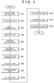
- FIG. 1 is a flowchart illustrating the manufacturing method of a coated conducting wire assembly according to the first example embodiment.
- FIG. 2 is a view showing a plurality of steps in the manufacturing method of a coated conducting wire assembly according to the first example embodiment. First, the plurality of steps to continuously manufacture an assembly conductor 202 from a conducting wire group 198 using a manufacturing apparatus 140 will be described. In FIG. 2 , the conducting wire group 198 is shown with conducting wires 109 lined up in a direction from the back to the front of the paper on which FIG. 2 is drawn (i.e., in a Y direction in this case).
- a wire feeder 141 feeds the conducting wire group 198 into a first pressure roller 142.
- the conducting wires 109 are linear bodies that have generally circular cross-sectional shapes.
- the conducting wires 109 make up a portion of the conducting wire group 198 that form peripheral wires 110.
- the conducting wires 109 are made of material that conducts electricity, e.g., pure copper or a copper alloy.
- the first pressure roller 142 receives the conducting wire group 198 from the wire feeder 141, and plastically deforms the conducting wires 109 of the conducting wire group 198 as shown in frame 162 to form the peripheral wires 110 (single wire rolling step S1).
- the cross-sectional shape of the peripheral wires 110 may be deformed from a circular shape having isotropy in which the cross-sectional shape does not change when the peripheral wires 110 are rotated, to an anisotropic cross-sectional shape having anisotropy in which the cross-sectional shape changes when the peripheral wires 110 are rotated, e.g., deformed to a trapezoidal shape in which the lengths of an upper base and a lower base are different.
- an anisotropic cross-sectional shape examples include a trapezoidal shape, a fan shape, an arc shape, and a triangular shape, and the like.
- the wires inside a wire group 199 formed by the peripheral wires 110 and a core wire 130 are arranged in a straight line. That is, the wires of the wire group 199 are arranged lined up in a line in a direction (the Y direction here) perpendicular to the feeding direction of the wire group 199 (i.e., the long direction (the X direction here) of the wires in the wire group 199). More specifically, the peripheral wires 110 are arranged such that surfaces corresponding to the upper bases of the trapezoidal shapes are arranged alternately with surfaces corresponding to the lower bases of the trapezoidal shapes.
- the first pressure roller 142 has a pair of rollers, and is rotated by a driving mechanism, not shown, and feeds the wire group 199 to a transport device 144.
- the wire group 199 is shown with the wires lined up in a straight line in a direction from the back to the front of the paper on which FIG. 2 is drawn.
- the transport device 144 receives the wire group 199 from the first pressure roller 142.
- the transport device 144 expands the wires of the wire group 199 to create a positional relationship in which the peripheral wires 110 surround the core wire 130. More specifically, as shown in frame 163, the peripheral wires 110 are arranged in a radial shape centered around the core wire 130 (expanding step S2). At this time, the peripheral wires 110 are arranged such that the area of the outer peripheral surfaces is wider than the area of the inner peripheral surfaces. That is, in a cross-section of the peripheral wires 110, the longer the two bases, i.e., the upper base and the lower base, of the trapezoidal shape, is arranged on the outside and the shorter of the two bases is arranged on the inside.
- the transport device 144 aligns the position and orientation of the peripheral wires 110 such that the inner peripheral surfaces of the peripheral wires 110 face the sides of the core wire 130. That is, the inner peripheral surfaces of the peripheral wires 110 must follow the outer peripheral surface of the circular cylindrical shape, so the peripheral wires 110 must be arranged converting an angle such that the wire group 199 that has been transported with the surface that includes the upper base and the surface that includes the lower base of each peripheral wire 110 parallel to each other, becomes perpendicular to a virtual line that extends radially outward from the core wire 130.
- the transport device 144 feeds the wire group 199 to a clamp 145.
- the clamp 145 receives the wire group 199 from the transport device 144.
- the clamp 145 aligns the wire group 199, and arranges the peripheral wires 110 around the core wire 130 to form a bundled wire assembly, i.e., a wire assembly bundle 200 (bundle forming step S3).
- the clamp 145 forms the wire assembly bundle 200 such that the inner peripheral surfaces of the peripheral wires 110 face the sides of the outer surface of the core wire 130.
- the clamp 145 applies a predetermined pressure to a wire assembly bundle 200, in a direction toward the center of the wire assembly bundle 200. Therefore, as shown in frame 164, the core wire 130 and the peripheral wires 110 are brought close together, and the peripheral wires 110 are brought close to each other, in a cross-section 190 of the wire assembly bundle 200.
- the wire assembly bundle 200 passes through the clamp 145 and a rotator 146, and is then fed to a clamp 147.
- the clamp 145, the rotator 146, and the clamp 147 clamp the wire assembly bundle 200 and fix the axis of the wire assembly bundle 200. Moreover, the rotator 146 rotates in a predetermined rotational direction 150 and twists the wire assembly bundle 200 (twisting step S4), while the clamp 145, the rotator 146, and the clamp 147 remain clamping the wire assembly bundle 200. As a result, a twisted assembly conductor 201 is formed.
- the twisted assembly conductor 201 has a twisted portion that is twisted in a spiral around the core wire 130, and a reverse twisted portion that is twisted in the opposite direction from the twisting direction of the twisted portion, with the rotator 146 as the boundary between the two portions.
- the twisted assembly conductor 201 may also have a non-twisted portion that runs parallel to the axis of the core wire 130, between the twisted portion and the reverse twisted portion. More specifically, the twisted assembly conductor 201 has a parallel portion 201a, a left-wound portion 201b, and a right-wound portion 201c, as shown in FIG. 3.
- FIG. 3 is a view showing the conducting wire assembly in one step of the manufacturing method of the coated conducting wire assembly according to the first example embodiment.
- the parallel portion 201a, the left-wound portion 201b, and the right-wound portion 201c are arranged in order of the left-wound portion 201b, the parallel portion 201a, the right-wound portion 201c, and the parallel portion 201a, in the advancing direction of the twisted assembly conductor 201 (i.e., in the X direction here).
- the parallel portion 201a, the left-wound portion 201b, the parallel portion 201 a, and the right-wound portion 201 c, and the parallel portion 201a are formed when the twisting step S4 is performed once.
- the parallel portion 201a, the left-wound portion 201b, the parallel portion 201a, the right-wound portion 201c, and the parallel portion 201a equal 1P (pitch).
- the twisted assembly conductor 201 is an assembly conductor in which the core wire 130 and the peripheral wires 110 that have a predetermined shape are aligned. Therefore, the rotator 146 is able to form the cross-section 191 in which the generally circular shape of the cross-section 190 is maintained.
- the clamp 147 applies a predetermined pressure to the twisted assembly conductor 201, in a direction toward the center of the twisted assembly conductor 201. Therefore, the core wire 130 is brought into close contact with the peripheral wires 110, and the peripheral wires 110 are brought into close contact with each other.
- a second pressure roller 151 receives the twisted assembly conductor 201 from the clamp 147.
- This second pressure roller 151 has a pair of rollers, and is rotated by a driving mechanism, not shown, and essentially applies pressure in the vertical direction (the Z-axis direction here) in FIG. 2 when the twisted assembly conductor 201 has a generally flat shape.
- a third pressure roller 152 forms an outer wall surface 194 along a width direction (the Y-axis direction here) on upper and lower ends in FIG. 2 of the cross-section 192 of the assembly conductor 202, as shown in frame 167 (finishing rolling step S5).
- a wall surface along the vertical direction (the Z-axis direction here) may also be formed on left and right ends in FIG. 2 , using at least one pair of pressure rollers, as necessary.
- the assembly conductor 202 has a core wire 132 and peripheral wires 112.
- an oxidation furnace 153 receives the assembly conductor 202 from the third pressure roller 152 (see FIG. 2 ), as shown in FIG. 4.
- FIG. 4 is a view showing a plurality of steps in the manufacturing method of the coated conducting wire assembly according to the first example embodiment.
- An oxide film is formed inside the assembly conductor 202, i.e., between the core wire 132 (see FIG. 2 ) and the peripheral wires 112 (see FIG. 2 ), as well as between the peripheral wires 112, by heating the assembly conductor 202 to an internal oxidization temperature (internal oxidizing step S6).
- the assembly conductor 202 is wound on a winding roller 153a inside the oxidation furnace 153.
- This oxide film preferably electrically insulates the core wire 132 from the peripheral wires 112, as well as electrically insulates the peripheral wires 112 from each other. It is also preferable to apply an oxide film forming agent that forms an oxide film, before the internal oxidizing step S6.
- an insulation coating 204a is coated onto an assembly conductor 203 to form an externally coated conducting wire assembly 204 (outer coating forming step S7). More specifically, an insulation coating applying device 154 receives the assembly conductor 203. The assembly conductor 203 is led to a die hole 154b of a drawing die 154a. The insulation coating applying device 154 softens powder-like raw material 154d filled into a hopper 154c by heating beforehand, and injects the raw material 154d into the die hole 154b of the drawing die 154a and applies further pressure using a screw 154e. Then the assembly conductor 203 is drawn toward the downstream side from the die hole 154b of the drawing die 154a.
- the externally coated conducting wire assembly 204 is drawn from the die hole 154b of the drawing die 154a, with the insulation coating 204a formed on an outer peripheral surface of the assembly conductor 203. It is by these steps that the externally coated conducting wire assembly 204 is manufactured.
- the insulation coating 204a is preferably made of material having electrical insulating properties.
- Some examples of such material are PFA (tetrafluoroethylene perfluoroalkyl vinyl ether copolymer), PEEK (polyether ether ketone), PPS (polyphenylene sulfide), and enamel and the like. Untwisting deformation or twisting deformation may occur in the externally coated conducting wire assembly 204 due to heating and tension being applied in the outer coating forming step S7.
- the externally coated conducting wire assembly 204 is cooled to a predetermined temperature (cooling step S8). More specifically, first, a cooling apparatus 155 receives the externally coated conducting wire assembly 204.
- the cooling apparatus 155 has a tank 155a that holds cooling water, and a pair of rollers 155b provided in the tank 155a.
- the cooling apparatus 155 passes the externally coated conducting wire assembly 204 between the pair of rollers 155b. As a result, the externally coated conducting wire assembly 204 is immersed inside the tank 155a and is thus able to be cooled.
- pressure is applied to the externally coated conducting wire assembly 204 to increase the straightness of the externally coated conducting wire assembly 204 (straightening step S9). More specifically, the externally coated conducting wire assembly 204 is fed to pairs of rollers 156a and 156b that are lined up in a direction substantially perpendicular to the axis of the externally coated conducting wire assembly 204. The pairs of rollers 156a and 156b each apply pressure to the externally coated conducting wire assembly 204. The direction in which this pressure is applied is a direction that is substantially perpendicular to the axis of the externally coated conducting wire assembly 204. The direction in which the pair of rollers 156a are lined up may also be substantially perpendicular to the direction in which the pair of rollers 156b are lined up.
- FIGS. 5 to 8 are views showing steps in the manufacturing method of the coated conducting wire assembly according to the first example embodiment. More specifically, a die 157b is provided below the externally coated conducting wire assembly 204, and the externally coated conducting wire assembly 204 is cut shorter by lowering a punch 157a from above the externally coated conducting wire assembly 204. As a result, a short conducting wire assembly 205 is formed. The length of this short conducting wire assembly 205 may be determined according to the usage application of the coated conducting wire assembly that is the finished product of this manufacturing method.
- the length of the short conducting wire assembly 205 may be determined according to the length of the short coil. Also, the length of the short conducting wire assembly 205 may be determined according to the size of manufacturing equipment such as an annealing furnace 40 that will be described later, or a clamp unit 20 that will also described later.
- both end portions of an outer coating 205a of the short conducting wire assembly 205 are cut using a disk-shaped cutter 158 (precutting step S11). While both end portions of the outer coating 205a are cut, conducting wire, not shown, of the short conducting wire assembly 205 is not cut, so the conducting wire, not shown, of the short conducting wire assembly 205 is not damaged.
- both end portions of the outer coating 205a are stripped (i.e., removed) using a blade 159, such that a partially coated conducting wire assembly 206 is formed (stripping step S12), as shown in FIG. 8 . More specifically, both end portions of the cut outer coating 205a are stripped by inserting the blade 159 into the outer coating 205a and moving the blade 159 toward the end side of the short conducting wire assembly 205.
- the partially coated conducting wire assembly 206 includes an insulation coating 206a, and a conducting wire assembly 206b that is covered by the insulation coating 206a. At least the center portion of the conducting wire assembly 206b is covered by the insulation coating 206a, and is thus electrically insulated. Both end portions (also referred to simply as "conducting portions”) of the conducting wire assembly 206b are not covered by the insulation coating 206a and are thus exposed and able to conduct electricity.
- the partially coated conducting wire assembly 206 is heated until it reaches an annealing temperature while tension is applied, and this temperature is then for a predetermined period of time (annealing step S 13).
- FIG. 9 is a flowchart illustrating steps in the manufacturing method of the coated conducting wire assembly according to the first example embodiment.
- FIG. 10 is a perspective view of the clamp unit used in the manufacturing method of the coated conducting wire assembly according to the first example embodiment.
- FIG. 11 is a front view of the clamp unit used in the manufacturing method of the coated conducting wire assembly according to the first example embodiment.
- FIG. 12 is a view showing a step in the manufacturing method of the coated conducting wire assembly according to the first example embodiment.
- the clamp unit 20 includes a base 21, a clamp supporting portion 22, a clamp 23, a spring supporting portion 24, a rod 25, a clamp supporting portion 26, and a clamp 27.
- the base 21 is a rectangular plate-like body
- the clamp supporting portion 22 is a blockish body provided on one end of the base 21.
- the spring supporting portion 24 is a blockish body provided on the other end portion side of the base 21.
- the rod 25 is slidably inserted into the spring supporting portion 24 via a spring, not shown.
- the clamp supporting portion 26 is connected to the rod 25 on the other end side of the base 21, and is provided so as to be able to move on the other end of the base 21.
- the clamp 27 is supported by the clamp supporting portion 26.
- the clamp 23 and the clamp 27 are arranged facing each other on the same virtual axis V1.
- the virtual axis V1 may be substantially parallel to the long direction of the base 21.
- the clamp 23 and the clamp 27 are, to be more precise, fixing implements, e.g., chuck devices, that fix the partially coated conducting wire assembly 206 in a predetermined position by clamping it.
- tension is applied to the partially coated conducting wire assembly 206 using the clamp unit 20 (clamping step S131). More specifically, the clamp unit 20 is able to clamp the partially coated conducting wire assembly 206 by clamping one end portion of the partially coated conducting wire assembly 206 with the clamp 23, while clamping the other end portion of the partially coated conducting wire assembly 206 with the clamp 27.
- the rod 25 and the clamp supporting portion 26 are pushed on by the restoring force of the spring, and the clamp 27 is pushed in a direction away from the clamp 23. Therefore, tension is applied to at least extend the partially coated conducting wire assembly 206 straight on the virtual axis V1.
- the other end portion of the partially coated conducting wire assembly 206 may be kept from twisting, so as to correct untwisting deformation or twisting deformation that may occur in the outer coating forming step S7 and the like, with respect to the one end portion of the partially coated conducting wire assembly 206.
- the phrase "kept from twisting" means that the twisting angle, i.e., the angle of the other end portion of the partially coated conducting wire assembly 206 with respect to the one end portion of the partially coated conducting wire assembly 206, is preferably substantially 0° (zero degrees).
- annealing is performed by heating and holding the partially coated conducting wire assembly 206 (furnace heating and holding step S132). More specifically, as shown in FIG. 12 , the clamp unit 20 that is clamping the partially coated conducting wire assembly 206 is placed on a conveyer 10 arranged inside the annealing furnace 40. A plurality of the clamp units 20 that are arranged such that the axes of the partially coated conducting wire assemblies 206 are along the width direction of the conveyer 10 may be lined up in the moving direction of the conveyer 10. The partially coated conducting wire assemblies 206 are arranged in a line.
- the annealing furnace 40 is able to heat an object to be heated that is arranged inside a furnace chamber, not shown, of the annealing furnace 40, by emitting infrared radiation or generating heated air, for example.
- the conveyer 10 rotates rotating rollers 11 and 12 in the same direction to move a belt 13 while maintaining the annealing temperature.
- a plurality of the clamp units 20 are able to pass through the annealing furnace 40, so annealing is able to be applied continuously to the plurality of partially coated conducting wire assemblies 206.
- the partially coated conducting wire assemblies that have been shortened by the cutting step S10 are arranged in a line, annealing is able to be performed using the compact full length of the annealing furnace in the moving direction of the conveyer 10. Also, the adhesion strength between the insulation coating 206a and the conducting wire assembly 206b is able to be increased by annealing.
- the partially coated conducting wire assembly 206 is shorter than the externally coated conducting wire assembly 204 (see FIGS. 4 to 6 ), so the partially coated conducting wire assembly 206 is easy to maneuver. Therefore, heating treatment is able to be performed for each partially coated conducting wire assembly 206, so the heating apparatus such as the annealing furnace 40 is able to be smaller. Also, tension is applied individually to the partially coated conducting wire assemblies 206, so the applied tension is able to be reduced. Therefore, the device that applies the tension, e.g., the clamp unit 20, is able to be smaller.
- the conducting wire assembly 206b may include copper wire made of copper or a copper alloy, and a copper oxide film made of copper oxide that covers this copper wire.
- the copper oxide film of the conducting wire assembly 206b and the insulation coating 206a that is made of resin into which LCP (liquid crystal polymer) has been blended are bonded by a hydrogen bond.
- the adhesion strength between the insulation coating 206a and the conducting wire assembly 206b is increased by heating and holding the partially coated conducting wire assembly 206, while inhibiting twisting by applying tension to the partially coated conducting wire assembly 206.
- FIGS. 13 and 14 are views showing one example of the conducting wire assembly manufactured using the manufacturing method of the coated conducting wire assembly according to the example embodiment.
- the one end portion 207a has a side surface 207e
- the another end portion 207c has a side surface 207f.
- the conducting wire assembly 207 is shown as a single conducting wire in order to facilitate understanding.
- a twisting angle ⁇ formed by the side surface 207e and the side surface 207f intersecting each other is smaller than an angle ⁇ (see FIG.
- any twisting deformation of the conducting wire assembly 207 that might occur in the outer coating forming step S7 is able to be corrected because the twisting angle of the conducting wire assembly 207 is small.
- the manufacturing method of the coated conducting wire assembly according to the first example embodiment described above thus makes it possible to manufacture a coated conducting wire assembly in which twisting deformation is corrected.
- a motor is able to be formed using the obtained conducting wire assembly 207. More specifically, after the conducting wire assembly has been cooled using an air blower, short coil wires, not shown, that are curved in a general U-shape or a general C-shape for example, are formed by press forming. Then, after being inserted into slots in a stator main body, the short coil wires are extended. The end portions of the short coil wires are welded together to form a coil.
- a motor, not shown, is then able to be formed by arranging the formed coil on, for example, a stator, and the like.
- the twisting deformation of the conducting wire assembly 207 is small, so the conducting wire assembly 207 is able to be assembled to the stator main body or the like with good assembly accuracy. Therefore, a motor in which the conducting wire assembly is assembled with good accuracy is able to be manufactured.
- This kind of motor may be used mounted in a vehicle such as a hybrid vehicle or a robot, for example.
- FIG. 15 is a flowchart illustrating steps in the manufacturing method of the coated conducting wire assembly according to the second example embodiment.
- FIG. 16 is a front view of a clamp unit used in one of the steps in the manufacturing method of the coated conducting wire assembly according to the second example embodiment.
- FIG. 17 is a view showing one of the steps in the manufacturing method of the coated conducting wire assembly according to the second example embodiment.
- the manufacturing method of the coated conducting wire assembly according to the second example embodiment has the same steps as the manufacturing method of the coated conducting wire assembly according to the first example embodiment, except that an annealing step S213 is performed instead of the annealing step S 13.
- the steps from the single wire rolling step S1 to the stripping step S2 are performed just as they are in the manufacturing method of the coated conducting wire assembly according to the first example embodiment.
- the partially coated conducting wire assembly 206 is heated to the annealing temperature while tension is applied, and is then kept at this annealing temperature for a predetermined period of time (annealing step S213).
- tension is applied to the partially coated conducting wire assembly 206 using a clamp unit 30 (clamping step S2131), as shown in FIG. 16 .
- the clamp unit 30 has the same structure as the clamp unit 20, except that it includes a DH (Direct resistance Heating) power supply 28 and a conducting wire 29.
- the DH power supply 28 of the clamp unit 30 is detachably connected to the clamps 23 and 27 via the clamp supporting portions 22 and 26, and the conducting wire 29.
- the conducting wire 29 is electrically connected to one end portion and the other end portion of the partially coated conducting wire assembly 206.
- the DH power supply 28 supplies current to the partially coated conducting wire assembly 206 via the conducting wire 29.
- Tension is applied to the partially coated conducting wire assembly 206 by clamping both end portions of the partially coated conducting wire assembly 206 with the clamps 23 and 27 of the clamp unit 30, just as in the clamping step S 131.
- the partially coated conducting wire assembly 206 is heated by direct resistance heating (direct resistance heating step S2132). More specifically, current is supplied to the partially coated conducting wire assembly 206 by the DH power supply 28, and Joule heat is generated inside the partially coated conducting wire assembly 206, e.g., in the conducting wire assembly 206b. As a result, the temperature of the partially coated conducting wire assembly 206 rises to the annealing temperature or close thereto. When heating is performed from outside the partially coated conducting wire assembly 206, as with heating by the annealing furnace 40 (see FIG.
- the insulation coating 206a acts as thermal insulating material, so heat is not easily transmitted to the contact portion between the conducting wire assembly 206b and the insulation coating 206a. Therefore, when heating by direct resistance heating in the direct resistance heating step S2132, a tremendous amount of heat tends to be generated in a short period of time in the object to be heated, compared to when heating by the annealing furnace 40 (see FIG. 12 ) in the furnace heating and holding step S132. Therefore, the temperature of the partially coated conducting wire assembly 206 is able to be raised to the annealing temperature in a short period of time.
- the direct resistance heating step S2132 may be performed inside the furnace chamber of the annealing furnace 40 or outside the furnace chamber of the annealing furnace 40.
- the partially coated conducting wire assembly 206 is put, clamp unit 30 and all, into the annealing furnace 40, and then heated and held (furnace heating and holding step S2133). More specifically, the DH power supply 28 and the conducting wire 29 are removed from the clamp supporting portions 22 and 26. Then, the clamp unit 30 that clamps the partially coated conducting wire assembly 206 is placed on a conveyer 10 that is arranged inside the annealing furnace 40, similar to the furnace heating and holding step S132. The conveyer 10 rotates the rotating rollers 11 and 12 in the same direction to move the belt 13, while the partially coated conducting wire assembly 206 is kept at the annealing temperature by the annealing furnace 40.
- a plurality of the clamp units 30 are able to pass through the annealing furnace 40, so annealing is able to be applied continuously to the plurality of partially coated conducting wire assemblies 206.
- the clamp unit 30 that clamps the partially coated conducting wire assembly 206 may also be placed on the conveyer 10 that is arranged inside the annealing furnace 40, while the DH power supply 28 and the conducting wire 29 are attached to the clamp supporting portions 22 and 26, as necessary.
- the one end portion and the other end portion of the partially coated conducting wire assembly 206 are often at a low temperature because they tend not to rise in temperature as easily as the other portions.
- the heat capacity of the clamp supporting portions 22 and 26 and the clamps 23 and 27 is larger than the heat capacity of the partially coated conducting wire assembly 206.
- the annealing furnace 40 heats the partially coated conducting wire assembly 206 and the clamp unit 30 evenly, so every portion of the partially coated conducting wire assembly 206 is able to be evenly heated and held.
- the furnace heating and holding step S2133 can be omitted if twisting deformation is sufficiently corrected by the direct resistance heating step S2132 alone.
- a coated conducting wire assembly in which twisting deformation has been corrected is able to be manufactured with high productivity by raising the temperature to the annealing temperature by direct resistance heating.
- FIG. 18 is a graph showing the twisting angle with respect to a measurement position.
- Example 1 a conducting wire assembly was manufactured using the manufacturing method of the coated conducting wire assembly according to the first example embodiment.
- a conducting wire assembly was manufactured using a manufacturing method having the same steps as the manufacturing method of the coated conducting wire assembly according to the first example embodiment, except for the annealing step S13. More specifically, in a step in the Comparative example 1 that corresponds to the annealing step S13, annealing was performed by heating and holding the conducting wire assembly as it is using an annealing furnace, without applying tension using a clamp unit or the like.
- Example 1 the twisting angle of the partially coated conducting wire assembly was measured after the stripping step S12 was complete but before the annealing step was started.
- the partially coated conducting wire assembly will be referred to as an "unannealed product”.
- the twisting angle in Example 1 and the twisting angle in Comparative example 1 were measured.
- the measurement results are shown in FIG. 18 .
- the measurement position is the distance from one end to the other end of the coated conducting wire assembly.
- a suitable range for the twisting angle is an upper limit of +2 degrees and a lower limit of -2 degrees. When the twisting angle is within this suitable range, the conducting wire assembly is able to be assembled to a motor or the like with good accuracy.
- Example 1 the twisting angle was small compared to the twisting angle of the unannealed product. In Example 1, the twisting angle decreased due to the annealing step S13. Also in Example 1, the twisting angle is within the suitable range for the twisting angle throughout all parts. Therefore, the conducting wire assembly of Example 1 is able to be assembled to a motor or the like with good accuracy.
- Comparative example 1 the twisting angle was large compared to the twisting angle of the unannealed product. In Comparative example 1, the twisting angle is thought to have increased due to the step corresponding to the annealing step S13 described above.
- FIG. 19 is a graph illustrating temperature with respect to heating time.
- a conducting wire assembly having the same structure as the partially coated conducting wire assembly 206 (see FIG. 10 ) without the insulation coating 206a was heated and held using a thermostatic chamber.
- the thermostatic chamber is able to heat an object to be heated that is arranged inside the thermostatic chamber, by generating heated air.
- the conducting wire assembly was then heated.
- This heated and held conducting wire assembly that lacks an insulation coating has the same structure as the conducting wire assembly 206b, and is made from a plurality of copper wires.
- the annealing temperature was approximately 320°C.
- a conducting wire assembly that has the same structure as the partially coated conducting wire assembly 206 (see FIG. 10 ) was heated and held using a thermostatic chamber, not shown, just as in Test example 1.
- This heated and held conducting wire assembly includes a conducting wire assembly that is made from a plurality of copper wires, and an insulation coating made of fluorine resin. Also, the annealing temperature here was approximately 320°C.
- a conducting wire assembly that has the same structure as the partially coated conducting wire assembly 206 (see FIG. 10 ) was heated by direct resistance heating, just as in the direct resistance heating step S2132 (see FIG. 15 ) in the manufacturing method according to the second example embodiment.
- This heated and held conducting wire assembly includes a conducting wire assembly that is made from a plurality of copper wires, and an insulation coating made of fluorine resin. Also, the annealing temperature here was approximately 320°C.
- Heating in Text examples 1 to 3 was started, and, after reaching the annealing temperature, the temperatures of the conducting wire assemblies were measured at least until the temperatures stabilized. These measurement results are shown in FIG. 19 .
- Test examples 1 and 2 approximately two minutes passed until the temperatures of the conducting wire assemblies reached the annealing temperature.
- Test example 3 approximately 0.1 minute passed until the temperature of the conducting wire assembly reached the annealing temperature. Therefore, the elapsed time until the temperature of the conducting wire assembly reached the annealing temperature was shorter in Test example 3 than it was in Test examples 1 and 2. That is, the rate of temperature increase in Test example 3 was faster than the rates of temperature increase in Test examples 1 and 2.
- One reason for this is that direct resistance heating generates Joule heat in the conducting wire assembly, so there is a tendency for the temperature to rise more rapidly compared to heating with a thermostatic chamber or an annealing furnace.
- the invention is not limited to the example embodiments described above. That is, suitable modifications within the scope of the invention are also possible.
- the steps from the cutting step S10 to the annealing step S13 are performed, but an annealing step S313 may be performed instead of the steps from the cutting step S10 to the annealing step S13.
- the annealing step S313 may be performed using an annealing apparatus 50 shown in FIG. 20 .
- the annealing apparatus 50 includes a furnace chamber 51, a holding base 52, two roller supporting portions 53 provided one on each end portion of the holding base 52, and two rollers 54 that are rotatably supported by the roller supporting portions 53, respectively.
- Each of the two rollers 54 is provided with technical means that enables it to rotate, rotate in reverse, and stop.
- An end portion of the partially coated conducting wire assembly 206 is wound around each of the two rollers 54.
- Tension is applied to the partially coated conducting wire assembly 206 by the rollers 54 rotating in opposite directions.
- tension is applied such that the partially coated conducting wire assembly 206 extends out straight.
- the other end portion of the partially coated conducting wire assembly 206 is preferably prevented from twisting with respect to the one end portion of the partially coated conducting wire assembly 206.
- the twisting angle i.e., the angle of the other end portion of the partially coated conducting wire assembly 206 with respect to the one end portion of the partially coated conducting wire assembly 206, is preferably 0° (zero degrees).
- Annealing may be performed by heating and holding the furnace chamber 51. Also, according to this kind of manufacturing method of a conducting wire assembly, annealing may be performed even if the steps from the cutting step S10 to the stripping step S12 are omitted. Tension may also be applied to the partially coated conducting wire assembly 206 by providing a mechanism that moves at least one of the roller supporting portions 53, and changing the distance between the roller supporting portions 53 while rotation of the rollers 54 is stopped.
- the steps from the single wire rolling step S1 to the annealing step S13 and S132 are performed, but at least one of the steps from the single wire rolling step S1 to the annealing step S13 and S132 may be omitted as necessary.
- annealing is performed while tension is applied, but tension may be applied at the same time that annealing starts or after annealing has started.
Landscapes
- Engineering & Computer Science (AREA)
- Power Engineering (AREA)
- Manufacturing & Machinery (AREA)
- Manufacture Of Motors, Generators (AREA)
- Insulated Conductors (AREA)
- Processes Specially Adapted For Manufacturing Cables (AREA)
- Heat Treatment Of Strip Materials And Filament Materials (AREA)
Abstract
Description
- The invention relates to a manufacturing method of a coated conducting wire assembly.
- A coated conducting wire assembly that is covered by an insulation coating having electrical insulation properties is known. For example,
JP 2009-199749 A - In the process of covering the conducting wire bundle with the coating, twisting deformation may occur in a conducting wire assembly due to the conducting wire assembly being heated while tension is applied it.
- For example, as shown in
FIG. 21 , a conductingwire assembly 901 is formed by twisting a bundled conducting wire bundle, not shown. This conductingwire assembly 901 has a left-wound portion 901b that is twisted around an axis of the conductingwire assembly 901, aparallel portion 901a that extends straight in the axial direction, and a right-wound portion 901c that is twisted in the opposite direction from the left-wound portion 901b. Untwisting deformation occurs in the conductingwire assembly 901 in a process to cover the conductingwire assembly 901 with a coating, and the like. Untwisting deformation is twisting deformation in which the left-wound portion 901b and the right-wound portion 901c loosen, or more specifically, in which the conducting wire bundle is twisted in arotational direction 902 that is opposite the rotational direction in which the conducting wire bundle is twisted. This twisting deformation causes theparallel portion 901a to expand, and the left-wound portion 901b and the right-wound portion 901c to decrease. - When such untwisting deformation occurs, one
end portion 907a of a coated conductingwire assembly 907 may twist-deform with respect to theother end portion 907c of the coated conductingwire assembly 907, as shown inFIG. 22 , for example. Also, a twisting angle α formed by the intersection of aside surface 907e of the oneend portion 907a and aside surface 907f of theother end portion 907c may reach a size that is undesirable for the coated conducting wire assembly, as shown inFIG. 23 . InFIGS. 22 and 23 , the coated conductingwire assembly 907 is shown as a single conducting wire to facilitate understanding. - Furthermore, the inventors of this application conceived of annealing the coated conducting wire assembly described above to a predetermined temperature, and then maintaining this temperature for a predetermined period of time. This kind of annealing ensures the necessary adhesion strength between the conducting wire assembly and the coating. However, annealing may also end up causing further twisting deformation in the coated conducting wire assembly.
- The invention thus provides a manufacturing method of a coated conducting wire assembly that corrects twisting deformation.
- A first aspect of the invention relates to a manufacturing method of a coated conducting wire assembly that includes forming a conducting wire assembly by twist-deforming a conducting wire bundle, forming a coated conducting wire assembly by covering the conducting wire assembly with an insulation coating, and annealing the coated conducting wire assembly. The conducting wire bundle is formed by bundling a plurality of conducting wires. The conducting wire assembly includes a parallel portion, a left-wound portion, and a right-wound portion. The annealing is heating and holding the coated conducting wire assembly at an annealing temperature, while applying tension to the covered conducting wire assembly.
- The adhesion strength between the coating and the conducting wire assembly is increased while inhibiting twisting of the conducting wire assembly, so a coated conducting wire assembly in which twisting deformation is corrected is able to be manufactured.
- In the aspect described above, the coated conducting wire assembly may include a conducting portion where the conducting wire assembly is exposed, on both ends. The annealing may include heating the coated conducting wire assembly to raise a temperature of the coated conducting wire assembly to the annealing temperature, and the heating may be performed by direct resistance heating by supplying a current to the conducting portion of the coated conducting wire assembly.
- According to this aspect, when heating is performed from outside the coated conducting wire assembly, the insulation coating acts as thermal insulating material, so heat is not easily transmitted to the contact portion between the conducting wire assembly and the insulation coating. However, the temperature of the coated conducting wire assembly is able to be raised to the annealing temperature in a short period of time by generating Joule heat inside the conducting wire assembly of the coated conducting wire assembly. Therefore, a coated conducting wire assembly in which twisting deformation has been corrected is able to be manufactured with high productivity.
- In the aspect described above, the annealing may include applying tension to the coated conducting wire assembly, while both end portions of the coated conducting wire assembly are fixed such that an angle of twist from untwisting deformation becomes substantially zero. The untwisting deformation is caused by return deformation that occurs as the coated conducting wire assembly is formed.
- According to this aspect, tension is applied while further inhibiting twisting of the coated conducting wire assembly, so a coated conducting wire assembly in which twisting deformation is even more reliably corrected is able to be manufactured.
- In the aspect described above, the coated conducting wire assembly may be shortened by cutting the coated conducting wire assembly before the annealing.
- According to this aspect, the coated conducting wire assembly is easier to maneuver because it is shorter. Therefore, heating treatment is able to be performed for each shortened coated conducting wire assembly, so the heating apparatus or the like such is able to be smaller. Also, tension is applied individually to the shortened coated conducting wire assemblies, so the applied tension is able to be reduced. Therefore, the device that applies the tension is able to be smaller.
- The invention is thus able to provide a manufacturing method of a coated conducting wire assembly that corrects twisting deformation.
- Features, advantages, and technical and industrial significance of exemplary embodiments of the invention will be described below with reference to the accompanying drawings, in which like numerals denote like elements, and wherein:
-
FIG. 1 is a flowchart illustrating a manufacturing method of a coated conducting wire assembly according to a first example embodiment of the invention; -
FIG. 2 is a view showing a plurality of steps in the manufacturing method of the coated conducting wire assembly according to the first example embodiment; -
FIG. 3 is a view showing the conducting wire assembly in one of the steps in the manufacturing method of the coated conducting wire assembly according to the first example embodiment; -
FIG. 4 is a view showing the plurality of steps in the manufacturing method of the coated conducting wire assembly according to the first example embodiment; -
FIG. 5 is a view showing one of the steps in the manufacturing method of the coated conducting wire assembly according to the first example embodiment; -
FIG. 6 is a view showing one of the steps in the manufacturing method of the coated conducting wire assembly according to the first example embodiment; -
FIG. 7 is a view showing one of the steps in the manufacturing method of the coated conducting wire assembly according to the first example embodiment; -
FIG. 8 is a view showing one of the steps in the manufacturing method of the coated conducting wire assembly according to the first example embodiment; -
FIG. 9 is a flowchart illustrating steps in the manufacturing method of the coated conducting wire assembly according to the first example embodiment; -
FIG. 10 is a perspective view of a clamp unit used in the manufacturing method of the coated conducting wire assembly according to the first example embodiment; -
FIG. 11 is a front view of the clamp unit used in the manufacturing method of the coated conducting wire assembly according to the first example embodiment; -
FIG. 12 is a view showing one of the steps in the manufacturing method of the coated conducting wire assembly according to the first example embodiment; -
FIG. 13 is a view showing one example of a conducting wire assembly manufactured using the manufacturing method of the coated conducting wire assembly according to the first example embodiment; -
FIG. 14 is a view showing one example of a conducting wire assembly manufactured using the manufacturing method of the coated conducting wire assembly according to the first example embodiment; -
FIG. 15 is a flowchart illustrating steps in a manufacturing method of a coated conducting wire assembly according to a second example embodiment of the invention; -
FIG. 16 is a front view of a clamp unit used in one of the steps in the manufacturing method of the coated conducting wire assembly according to the second example embodiment; -
FIG. 17 is a flowchart illustrating one of the steps in the manufacturing method of the coated conducting wire assembly according to the second example embodiment; -
FIG. 18 is a graph showing a twisting angle with respect to a measurement position; -
FIG. 19 is a graph showing the temperature with respect to heating time; -
FIG. 20 is a view showing another step of the manufacturing method of the coated conducting wire assembly according to the first example embodiment; -
FIG. 21 is a view showing a conducting wire assembly manufactured using a related manufacturing method of a coated conducting wire assembly; -
FIG. 22 is a view of an example of a conducting wire assembly manufactured using a related manufacturing method of a coated conducting wire assembly; and -
FIG. 23 is another view of the example of the conducting wire assembly manufactured using the related manufacturing method of a coated conducting wire assembly. - A manufacturing method of a coated conducting wire assembly according to a first example embodiment of the invention will now be described with reference to
FIGS. 1 to 14 .FIG. 1 is a flowchart illustrating the manufacturing method of a coated conducting wire assembly according to the first example embodiment.FIG. 2 is a view showing a plurality of steps in the manufacturing method of a coated conducting wire assembly according to the first example embodiment. First, the plurality of steps to continuously manufacture anassembly conductor 202 from aconducting wire group 198 using amanufacturing apparatus 140 will be described. InFIG. 2 , theconducting wire group 198 is shown with conductingwires 109 lined up in a direction from the back to the front of the paper on whichFIG. 2 is drawn (i.e., in a Y direction in this case). - As shown in
FIG. 2 , awire feeder 141 feeds theconducting wire group 198 into afirst pressure roller 142. As shown inframe 161, the conductingwires 109 are linear bodies that have generally circular cross-sectional shapes. The conductingwires 109 make up a portion of theconducting wire group 198 that formperipheral wires 110. The conductingwires 109 are made of material that conducts electricity, e.g., pure copper or a copper alloy. - The
first pressure roller 142 receives theconducting wire group 198 from thewire feeder 141, and plastically deforms the conductingwires 109 of theconducting wire group 198 as shown inframe 162 to form the peripheral wires 110 (single wire rolling step S1). Here, the cross-sectional shape of theperipheral wires 110 may be deformed from a circular shape having isotropy in which the cross-sectional shape does not change when theperipheral wires 110 are rotated, to an anisotropic cross-sectional shape having anisotropy in which the cross-sectional shape changes when theperipheral wires 110 are rotated, e.g., deformed to a trapezoidal shape in which the lengths of an upper base and a lower base are different. Examples of an anisotropic cross-sectional shape include a trapezoidal shape, a fan shape, an arc shape, and a triangular shape, and the like. Also, the wires inside awire group 199 formed by theperipheral wires 110 and acore wire 130 are arranged in a straight line. That is, the wires of thewire group 199 are arranged lined up in a line in a direction (the Y direction here) perpendicular to the feeding direction of the wire group 199 (i.e., the long direction (the X direction here) of the wires in the wire group 199). More specifically, theperipheral wires 110 are arranged such that surfaces corresponding to the upper bases of the trapezoidal shapes are arranged alternately with surfaces corresponding to the lower bases of the trapezoidal shapes. - The
first pressure roller 142 has a pair of rollers, and is rotated by a driving mechanism, not shown, and feeds thewire group 199 to atransport device 144. Thewire group 199 is shown with the wires lined up in a straight line in a direction from the back to the front of the paper on whichFIG. 2 is drawn. - The
transport device 144 receives thewire group 199 from thefirst pressure roller 142. Thetransport device 144 expands the wires of thewire group 199 to create a positional relationship in which theperipheral wires 110 surround thecore wire 130. More specifically, as shown inframe 163, theperipheral wires 110 are arranged in a radial shape centered around the core wire 130 (expanding step S2). At this time, theperipheral wires 110 are arranged such that the area of the outer peripheral surfaces is wider than the area of the inner peripheral surfaces. That is, in a cross-section of theperipheral wires 110, the longer the two bases, i.e., the upper base and the lower base, of the trapezoidal shape, is arranged on the outside and the shorter of the two bases is arranged on the inside. - Also, the
transport device 144 aligns the position and orientation of theperipheral wires 110 such that the inner peripheral surfaces of theperipheral wires 110 face the sides of thecore wire 130. That is, the inner peripheral surfaces of theperipheral wires 110 must follow the outer peripheral surface of the circular cylindrical shape, so theperipheral wires 110 must be arranged converting an angle such that thewire group 199 that has been transported with the surface that includes the upper base and the surface that includes the lower base of eachperipheral wire 110 parallel to each other, becomes perpendicular to a virtual line that extends radially outward from thecore wire 130. Thetransport device 144 feeds thewire group 199 to aclamp 145. - Continuing on, the
clamp 145 receives thewire group 199 from thetransport device 144. Theclamp 145 aligns thewire group 199, and arranges theperipheral wires 110 around thecore wire 130 to form a bundled wire assembly, i.e., a wire assembly bundle 200 (bundle forming step S3). Also, theclamp 145 forms thewire assembly bundle 200 such that the inner peripheral surfaces of theperipheral wires 110 face the sides of the outer surface of thecore wire 130. - The
clamp 145 applies a predetermined pressure to awire assembly bundle 200, in a direction toward the center of thewire assembly bundle 200. Therefore, as shown inframe 164, thecore wire 130 and theperipheral wires 110 are brought close together, and theperipheral wires 110 are brought close to each other, in across-section 190 of thewire assembly bundle 200. Thewire assembly bundle 200 passes through theclamp 145 and a rotator 146, and is then fed to aclamp 147. - The
clamp 145, the rotator 146, and theclamp 147 clamp thewire assembly bundle 200 and fix the axis of thewire assembly bundle 200. Moreover, the rotator 146 rotates in a predeterminedrotational direction 150 and twists the wire assembly bundle 200 (twisting step S4), while theclamp 145, the rotator 146, and theclamp 147 remain clamping thewire assembly bundle 200. As a result, atwisted assembly conductor 201 is formed. Here, thetwisted assembly conductor 201 has a twisted portion that is twisted in a spiral around thecore wire 130, and a reverse twisted portion that is twisted in the opposite direction from the twisting direction of the twisted portion, with the rotator 146 as the boundary between the two portions. Thetwisted assembly conductor 201 may also have a non-twisted portion that runs parallel to the axis of thecore wire 130, between the twisted portion and the reverse twisted portion. More specifically, thetwisted assembly conductor 201 has aparallel portion 201a, a left-wound portion 201b, and a right-wound portion 201c, as shown inFIG. 3. FIG. 3 is a view showing the conducting wire assembly in one step of the manufacturing method of the coated conducting wire assembly according to the first example embodiment. Theparallel portion 201a, the left-wound portion 201b, and the right-wound portion 201c are arranged in order of the left-wound portion 201b, theparallel portion 201a, the right-wound portion 201c, and theparallel portion 201a, in the advancing direction of the twisted assembly conductor 201 (i.e., in the X direction here). Theparallel portion 201a, the left-wound portion 201b, theparallel portion 201 a, and the right-wound portion 201 c, and theparallel portion 201a, are formed when the twisting step S4 is performed once. Here, theparallel portion 201a, the left-wound portion 201b, theparallel portion 201a, the right-wound portion 201c, and theparallel portion 201a equal 1P (pitch). - As shown in
frame 165 inFIG. 2 , thetwisted assembly conductor 201 is an assembly conductor in which thecore wire 130 and theperipheral wires 110 that have a predetermined shape are aligned. Therefore, the rotator 146 is able to form thecross-section 191 in which the generally circular shape of thecross-section 190 is maintained. - The
clamp 147 applies a predetermined pressure to thetwisted assembly conductor 201, in a direction toward the center of thetwisted assembly conductor 201. Therefore, thecore wire 130 is brought into close contact with theperipheral wires 110, and theperipheral wires 110 are brought into close contact with each other. - A
second pressure roller 151 receives thetwisted assembly conductor 201 from theclamp 147. Thissecond pressure roller 151 has a pair of rollers, and is rotated by a driving mechanism, not shown, and essentially applies pressure in the vertical direction (the Z-axis direction here) inFIG. 2 when thetwisted assembly conductor 201 has a generally flat shape. Furthermore, athird pressure roller 152 forms anouter wall surface 194 along a width direction (the Y-axis direction here) on upper and lower ends inFIG. 2 of thecross-section 192 of theassembly conductor 202, as shown in frame 167 (finishing rolling step S5). A wall surface along the vertical direction (the Z-axis direction here) may also be formed on left and right ends inFIG. 2 , using at least one pair of pressure rollers, as necessary. Theassembly conductor 202 has acore wire 132 andperipheral wires 112. - Continuing on, an
oxidation furnace 153 receives theassembly conductor 202 from the third pressure roller 152 (seeFIG. 2 ), as shown inFIG. 4. FIG. 4 is a view showing a plurality of steps in the manufacturing method of the coated conducting wire assembly according to the first example embodiment. An oxide film is formed inside theassembly conductor 202, i.e., between the core wire 132 (seeFIG. 2 ) and the peripheral wires 112 (seeFIG. 2 ), as well as between theperipheral wires 112, by heating theassembly conductor 202 to an internal oxidization temperature (internal oxidizing step S6). Theassembly conductor 202 is wound on a windingroller 153a inside theoxidation furnace 153. This oxide film preferably electrically insulates thecore wire 132 from theperipheral wires 112, as well as electrically insulates theperipheral wires 112 from each other. It is also preferable to apply an oxide film forming agent that forms an oxide film, before the internal oxidizing step S6. - Continuing on, an
insulation coating 204a is coated onto anassembly conductor 203 to form an externally coated conducting wire assembly 204 (outer coating forming step S7). More specifically, an insulationcoating applying device 154 receives theassembly conductor 203. Theassembly conductor 203 is led to adie hole 154b of adrawing die 154a. The insulationcoating applying device 154 softens powder-likeraw material 154d filled into ahopper 154c by heating beforehand, and injects theraw material 154d into thedie hole 154b of the drawing die 154a and applies further pressure using ascrew 154e. Then theassembly conductor 203 is drawn toward the downstream side from thedie hole 154b of thedrawing die 154a. Thus, the externally coatedconducting wire assembly 204 is drawn from thedie hole 154b of thedrawing die 154a, with theinsulation coating 204a formed on an outer peripheral surface of theassembly conductor 203. It is by these steps that the externally coatedconducting wire assembly 204 is manufactured. - Here, the
insulation coating 204a is preferably made of material having electrical insulating properties. Some examples of such material are PFA (tetrafluoroethylene perfluoroalkyl vinyl ether copolymer), PEEK (polyether ether ketone), PPS (polyphenylene sulfide), and enamel and the like. Untwisting deformation or twisting deformation may occur in the externally coatedconducting wire assembly 204 due to heating and tension being applied in the outer coating forming step S7. - Continuing on, the externally coated
conducting wire assembly 204 is cooled to a predetermined temperature (cooling step S8). More specifically, first, acooling apparatus 155 receives the externally coatedconducting wire assembly 204. Thecooling apparatus 155 has atank 155a that holds cooling water, and a pair ofrollers 155b provided in thetank 155a. Thecooling apparatus 155 passes the externally coatedconducting wire assembly 204 between the pair ofrollers 155b. As a result, the externally coatedconducting wire assembly 204 is immersed inside thetank 155a and is thus able to be cooled. - Continuing on, pressure is applied to the externally coated
conducting wire assembly 204 to increase the straightness of the externally coated conducting wire assembly 204 (straightening step S9). More specifically, the externally coatedconducting wire assembly 204 is fed to pairs ofrollers conducting wire assembly 204. The pairs ofrollers conducting wire assembly 204. The direction in which this pressure is applied is a direction that is substantially perpendicular to the axis of the externally coatedconducting wire assembly 204. The direction in which the pair ofrollers 156a are lined up may also be substantially perpendicular to the direction in which the pair ofrollers 156b are lined up. - As shown in
FIGS. 5 and 6 , the externally coatedconducting wire assembly 204 is cut using a press 157 (cutting step S10).FIGS. 5 to 8 are views showing steps in the manufacturing method of the coated conducting wire assembly according to the first example embodiment. More specifically, adie 157b is provided below the externally coatedconducting wire assembly 204, and the externally coatedconducting wire assembly 204 is cut shorter by lowering apunch 157a from above the externally coatedconducting wire assembly 204. As a result, a shortconducting wire assembly 205 is formed. The length of this shortconducting wire assembly 205 may be determined according to the usage application of the coated conducting wire assembly that is the finished product of this manufacturing method. For example, when the usage application of the coated conducting wire assembly is a short coil for a motor, which will be described later, the length of the shortconducting wire assembly 205 may be determined according to the length of the short coil. Also, the length of the shortconducting wire assembly 205 may be determined according to the size of manufacturing equipment such as anannealing furnace 40 that will be described later, or aclamp unit 20 that will also described later. - As shown in
FIG. 7 , both end portions of anouter coating 205a of the shortconducting wire assembly 205 are cut using a disk-shaped cutter 158 (precutting step S11). While both end portions of theouter coating 205a are cut, conducting wire, not shown, of the shortconducting wire assembly 205 is not cut, so the conducting wire, not shown, of the shortconducting wire assembly 205 is not damaged. - Continuing on, both end portions of the
outer coating 205a are stripped (i.e., removed) using ablade 159, such that a partially coatedconducting wire assembly 206 is formed (stripping step S12), as shown inFIG. 8 . More specifically, both end portions of the cutouter coating 205a are stripped by inserting theblade 159 into theouter coating 205a and moving theblade 159 toward the end side of the shortconducting wire assembly 205. The partially coated conductingwire assembly 206 includes aninsulation coating 206a, and aconducting wire assembly 206b that is covered by theinsulation coating 206a. At least the center portion of theconducting wire assembly 206b is covered by theinsulation coating 206a, and is thus electrically insulated. Both end portions (also referred to simply as "conducting portions") of theconducting wire assembly 206b are not covered by theinsulation coating 206a and are thus exposed and able to conduct electricity. - Continuing on, the partially coated
conducting wire assembly 206 is heated until it reaches an annealing temperature while tension is applied, and this temperature is then for a predetermined period of time (annealing step S 13). - More specifically, while the partially coated
conducting wire assembly 206 is clamped by theclamp unit 20, the partially coatedconducting wire assembly 206 is put,clamp unit 20 and all, into theannealing furnace 40, then heated to a predetermined temperature and kept at this temperature for a predetermined period of time, as shown inFIGS. 10 to 12 with reference toFIG. 9. FIG. 9 is a flowchart illustrating steps in the manufacturing method of the coated conducting wire assembly according to the first example embodiment.FIG. 10 is a perspective view of the clamp unit used in the manufacturing method of the coated conducting wire assembly according to the first example embodiment.FIG. 11 is a front view of the clamp unit used in the manufacturing method of the coated conducting wire assembly according to the first example embodiment.FIG. 12 is a view showing a step in the manufacturing method of the coated conducting wire assembly according to the first example embodiment. - As shown in
FIGS. 10 and11 , theclamp unit 20 includes abase 21, aclamp supporting portion 22, aclamp 23, aspring supporting portion 24, arod 25, aclamp supporting portion 26, and aclamp 27. Thebase 21 is a rectangular plate-like body, and theclamp supporting portion 22 is a blockish body provided on one end of thebase 21. Thespring supporting portion 24 is a blockish body provided on the other end portion side of thebase 21. Therod 25 is slidably inserted into thespring supporting portion 24 via a spring, not shown. Theclamp supporting portion 26 is connected to therod 25 on the other end side of thebase 21, and is provided so as to be able to move on the other end of thebase 21. Theclamp 27 is supported by theclamp supporting portion 26. - The
clamp 23 and theclamp 27 are arranged facing each other on the same virtual axis V1. When theclamp supporting portion 26 moves, theclamp 27 moves on the virtual axis V1. The virtual axis V1 may be substantially parallel to the long direction of thebase 21. Theclamp 23 and theclamp 27 are, to be more precise, fixing implements, e.g., chuck devices, that fix the partially coatedconducting wire assembly 206 in a predetermined position by clamping it. - First, tension is applied to the partially coated
conducting wire assembly 206 using the clamp unit 20 (clamping step S131). More specifically, theclamp unit 20 is able to clamp the partially coatedconducting wire assembly 206 by clamping one end portion of the partially coatedconducting wire assembly 206 with theclamp 23, while clamping the other end portion of the partially coatedconducting wire assembly 206 with theclamp 27. Here, therod 25 and theclamp supporting portion 26 are pushed on by the restoring force of the spring, and theclamp 27 is pushed in a direction away from theclamp 23. Therefore, tension is applied to at least extend the partially coatedconducting wire assembly 206 straight on the virtual axis V1. The other end portion of the partially coatedconducting wire assembly 206 may be kept from twisting, so as to correct untwisting deformation or twisting deformation that may occur in the outer coating forming step S7 and the like, with respect to the one end portion of the partially coatedconducting wire assembly 206. Here, the phrase "kept from twisting" means that the twisting angle, i.e., the angle of the other end portion of the partially coatedconducting wire assembly 206 with respect to the one end portion of the partially coatedconducting wire assembly 206, is preferably substantially 0° (zero degrees). - Continuing on, annealing is performed by heating and holding the partially coated conducting wire assembly 206 (furnace heating and holding step S132). More specifically, as shown in
FIG. 12 , theclamp unit 20 that is clamping the partially coatedconducting wire assembly 206 is placed on aconveyer 10 arranged inside the annealingfurnace 40. A plurality of theclamp units 20 that are arranged such that the axes of the partially coatedconducting wire assemblies 206 are along the width direction of theconveyer 10 may be lined up in the moving direction of theconveyer 10. The partially coatedconducting wire assemblies 206 are arranged in a line. The annealingfurnace 40 is able to heat an object to be heated that is arranged inside a furnace chamber, not shown, of theannealing furnace 40, by emitting infrared radiation or generating heated air, for example. After the partially coatedconducting wire assembly 206 is heated to the annealing temperature by the annealingfurnace 40, theconveyer 10 rotates rotatingrollers belt 13 while maintaining the annealing temperature. As a result, a plurality of theclamp units 20 are able to pass through the annealingfurnace 40, so annealing is able to be applied continuously to the plurality of partially coatedconducting wire assemblies 206. Because the partially coated conducting wire assemblies that have been shortened by the cutting step S10 are arranged in a line, annealing is able to be performed using the compact full length of the annealing furnace in the moving direction of theconveyer 10. Also, the adhesion strength between theinsulation coating 206a and theconducting wire assembly 206b is able to be increased by annealing. Here, the partially coatedconducting wire assembly 206 is shorter than the externally coated conducting wire assembly 204 (seeFIGS. 4 to 6 ), so the partially coatedconducting wire assembly 206 is easy to maneuver. Therefore, heating treatment is able to be performed for each partially coated conductingwire assembly 206, so the heating apparatus such as the annealingfurnace 40 is able to be smaller. Also, tension is applied individually to the partially coatedconducting wire assemblies 206, so the applied tension is able to be reduced. Therefore, the device that applies the tension, e.g., theclamp unit 20, is able to be smaller. - For example, the
conducting wire assembly 206b may include copper wire made of copper or a copper alloy, and a copper oxide film made of copper oxide that covers this copper wire. In this case, when annealing is performed, the copper oxide film of theconducting wire assembly 206b and theinsulation coating 206a that is made of resin into which LCP (liquid crystal polymer) has been blended are bonded by a hydrogen bond. - Also, the adhesion strength between the
insulation coating 206a and theconducting wire assembly 206b is increased by heating and holding the partially coatedconducting wire assembly 206, while inhibiting twisting by applying tension to the partially coatedconducting wire assembly 206. - A
conducting wire assembly 207 is obtained through these steps. As shown inFIG. 13 , theconducting wire assembly 207 has oneend portion 207a and anotherend portion 207c.FIGS. 13 and 14 are views showing one example of the conducting wire assembly manufactured using the manufacturing method of the coated conducting wire assembly according to the example embodiment. The oneend portion 207a has aside surface 207e, and the anotherend portion 207c has aside surface 207f. InFIGS. 13 and 14 , theconducting wire assembly 207 is shown as a single conducting wire in order to facilitate understanding. As shown inFIG. 14 , a twisting angle β formed by theside surface 207e and theside surface 207f intersecting each other is smaller than an angle α (seeFIG. 23 ), and falls within a range of a suitable value for the coated conducting wire assembly. That is, it is thought that any twisting deformation of theconducting wire assembly 207 that might occur in the outer coating forming step S7 is able to be corrected because the twisting angle of theconducting wire assembly 207 is small. - The manufacturing method of the coated conducting wire assembly according to the first example embodiment described above thus makes it possible to manufacture a coated conducting wire assembly in which twisting deformation is corrected.
- A motor is able to be formed using the obtained
conducting wire assembly 207. More specifically, after the conducting wire assembly has been cooled using an air blower, short coil wires, not shown, that are curved in a general U-shape or a general C-shape for example, are formed by press forming. Then, after being inserted into slots in a stator main body, the short coil wires are extended. The end portions of the short coil wires are welded together to form a coil. A motor, not shown, is then able to be formed by arranging the formed coil on, for example, a stator, and the like. For example, the twisting deformation of theconducting wire assembly 207 is small, so theconducting wire assembly 207 is able to be assembled to the stator main body or the like with good assembly accuracy. Therefore, a motor in which the conducting wire assembly is assembled with good accuracy is able to be manufactured. This kind of motor may be used mounted in a vehicle such as a hybrid vehicle or a robot, for example. - Next, a manufacturing method of a coated conducting wire assembly according to a second example embodiment of the invention will be described with reference to
FIGS. 15 to 17 .FIG. 15 is a flowchart illustrating steps in the manufacturing method of the coated conducting wire assembly according to the second example embodiment.FIG. 16 is a front view of a clamp unit used in one of the steps in the manufacturing method of the coated conducting wire assembly according to the second example embodiment.FIG. 17 is a view showing one of the steps in the manufacturing method of the coated conducting wire assembly according to the second example embodiment. The manufacturing method of the coated conducting wire assembly according to the second example embodiment has the same steps as the manufacturing method of the coated conducting wire assembly according to the first example embodiment, except that an annealing step S213 is performed instead of theannealing step S 13. - First, the steps from the single wire rolling step S1 to the stripping step S2 are performed just as they are in the manufacturing method of the coated conducting wire assembly according to the first example embodiment.
- Then, the partially coated
conducting wire assembly 206 is heated to the annealing temperature while tension is applied, and is then kept at this annealing temperature for a predetermined period of time (annealing step S213). - More specifically, first, tension is applied to the partially coated
conducting wire assembly 206 using a clamp unit 30 (clamping step S2131), as shown inFIG. 16 . Theclamp unit 30 has the same structure as theclamp unit 20, except that it includes a DH (Direct resistance Heating)power supply 28 and aconducting wire 29. TheDH power supply 28 of theclamp unit 30 is detachably connected to theclamps clamp supporting portions conducting wire 29. Theconducting wire 29 is electrically connected to one end portion and the other end portion of the partially coatedconducting wire assembly 206. TheDH power supply 28 supplies current to the partially coatedconducting wire assembly 206 via theconducting wire 29. Tension is applied to the partially coatedconducting wire assembly 206 by clamping both end portions of the partially coatedconducting wire assembly 206 with theclamps clamp unit 30, just as in the clamping step S 131. - Continuing on, the partially coated
conducting wire assembly 206 is heated by direct resistance heating (direct resistance heating step S2132). More specifically, current is supplied to the partially coatedconducting wire assembly 206 by theDH power supply 28, and Joule heat is generated inside the partially coatedconducting wire assembly 206, e.g., in theconducting wire assembly 206b. As a result, the temperature of the partially coatedconducting wire assembly 206 rises to the annealing temperature or close thereto. When heating is performed from outside the partially coatedconducting wire assembly 206, as with heating by the annealing furnace 40 (seeFIG. 12 ) in the furnace heating and holding step S132 described above, theinsulation coating 206a acts as thermal insulating material, so heat is not easily transmitted to the contact portion between the conductingwire assembly 206b and theinsulation coating 206a. Therefore, when heating by direct resistance heating in the direct resistance heating step S2132, a tremendous amount of heat tends to be generated in a short period of time in the object to be heated, compared to when heating by the annealing furnace 40 (seeFIG. 12 ) in the furnace heating and holding step S132. Therefore, the temperature of the partially coatedconducting wire assembly 206 is able to be raised to the annealing temperature in a short period of time. The direct resistance heating step S2132 may be performed inside the furnace chamber of theannealing furnace 40 or outside the furnace chamber of theannealing furnace 40. - Finally, as shown in
FIG. 17 , the partially coatedconducting wire assembly 206 is put,clamp unit 30 and all, into theannealing furnace 40, and then heated and held (furnace heating and holding step S2133). More specifically, theDH power supply 28 and theconducting wire 29 are removed from theclamp supporting portions clamp unit 30 that clamps the partially coatedconducting wire assembly 206 is placed on aconveyer 10 that is arranged inside the annealingfurnace 40, similar to the furnace heating and holding step S132. Theconveyer 10 rotates therotating rollers belt 13, while the partially coatedconducting wire assembly 206 is kept at the annealing temperature by the annealingfurnace 40. As a result, a plurality of theclamp units 30 are able to pass through the annealingfurnace 40, so annealing is able to be applied continuously to the plurality of partially coatedconducting wire assemblies 206. Theclamp unit 30 that clamps the partially coatedconducting wire assembly 206 may also be placed on theconveyer 10 that is arranged inside the annealingfurnace 40, while theDH power supply 28 and theconducting wire 29 are attached to theclamp supporting portions - Upon completion of the direct resistance heating step S2132, the one end portion and the other end portion of the partially coated
conducting wire assembly 206 are often at a low temperature because they tend not to rise in temperature as easily as the other portions. One reason for this is that the heat capacity of theclamp supporting portions clamps conducting wire assembly 206. In the furnace heating and holding step S2133, the annealingfurnace 40 heats the partially coatedconducting wire assembly 206 and theclamp unit 30 evenly, so every portion of the partially coatedconducting wire assembly 206 is able to be evenly heated and held. The furnace heating and holding step S2133 can be omitted if twisting deformation is sufficiently corrected by the direct resistance heating step S2132 alone. - According to the manufacturing method of the coated conducting wire assembly according to the second example embodiment described above, a coated conducting wire assembly in which twisting deformation has been corrected is able to be manufactured with high productivity by raising the temperature to the annealing temperature by direct resistance heating.
- Next, examples in which conducting wire assemblies were manufactured using the manufacturing method of the coated conducting wire assembly according to the first example embodiment will be described with reference to
FIG. 18. FIG. 18 is a graph showing the twisting angle with respect to a measurement position. - In Example 1, a conducting wire assembly was manufactured using the manufacturing method of the coated conducting wire assembly according to the first example embodiment. In Comparative example 1, a conducting wire assembly was manufactured using a manufacturing method having the same steps as the manufacturing method of the coated conducting wire assembly according to the first example embodiment, except for the annealing step S13. More specifically, in a step in the Comparative example 1 that corresponds to the annealing step S13, annealing was performed by heating and holding the conducting wire assembly as it is using an annealing furnace, without applying tension using a clamp unit or the like.
- In Example 1, the twisting angle of the partially coated conducting wire assembly was measured after the stripping step S12 was complete but before the annealing step was started. Hereinafter, the partially coated conducting wire assembly will be referred to as an "unannealed product". Also, the twisting angle in Example 1 and the twisting angle in Comparative example 1 were measured. The measurement results are shown in
FIG. 18 . The measurement position is the distance from one end to the other end of the coated conducting wire assembly. A suitable range for the twisting angle is an upper limit of +2 degrees and a lower limit of -2 degrees. When the twisting angle is within this suitable range, the conducting wire assembly is able to be assembled to a motor or the like with good accuracy. - As shown in
FIG. 18 , in Example 1, the twisting angle was small compared to the twisting angle of the unannealed product. In Example 1, the twisting angle decreased due to the annealing step S13. Also in Example 1, the twisting angle is within the suitable range for the twisting angle throughout all parts. Therefore, the conducting wire assembly of Example 1 is able to be assembled to a motor or the like with good accuracy. - On the other hand, in Comparative example 1, the twisting angle was large compared to the twisting angle of the unannealed product. In Comparative example 1, the twisting angle is thought to have increased due to the step corresponding to the annealing step S13 described above.
- Next, test examples will be described with reference to
FIG. 19. FIG. 19 is a graph illustrating temperature with respect to heating time. - In Test example 1, a conducting wire assembly having the same structure as the partially coated conducting wire assembly 206 (see
FIG. 10 ) without theinsulation coating 206a was heated and held using a thermostatic chamber. The thermostatic chamber is able to heat an object to be heated that is arranged inside the thermostatic chamber, by generating heated air. The conducting wire assembly was then heated. This heated and held conducting wire assembly that lacks an insulation coating has the same structure as theconducting wire assembly 206b, and is made from a plurality of copper wires. Also, the annealing temperature was approximately 320°C. - Also, in Test example 2, a conducting wire assembly that has the same structure as the partially coated conducting wire assembly 206 (see
FIG. 10 ) was heated and held using a thermostatic chamber, not shown, just as in Test example 1. This heated and held conducting wire assembly includes a conducting wire assembly that is made from a plurality of copper wires, and an insulation coating made of fluorine resin. Also, the annealing temperature here was approximately 320°C. - Moreover, in Test example 3, a conducting wire assembly that has the same structure as the partially coated conducting wire assembly 206 (see
FIG. 10 ) was heated by direct resistance heating, just as in the direct resistance heating step S2132 (seeFIG. 15 ) in the manufacturing method according to the second example embodiment. This heated and held conducting wire assembly includes a conducting wire assembly that is made from a plurality of copper wires, and an insulation coating made of fluorine resin. Also, the annealing temperature here was approximately 320°C. - Heating in Text examples 1 to 3 was started, and, after reaching the annealing temperature, the temperatures of the conducting wire assemblies were measured at least until the temperatures stabilized. These measurement results are shown in
FIG. 19 . - In Test examples 1 and 2, approximately two minutes passed until the temperatures of the conducting wire assemblies reached the annealing temperature. On the other hand, in Test example 3, approximately 0.1 minute passed until the temperature of the conducting wire assembly reached the annealing temperature. Therefore, the elapsed time until the temperature of the conducting wire assembly reached the annealing temperature was shorter in Test example 3 than it was in Test examples 1 and 2. That is, the rate of temperature increase in Test example 3 was faster than the rates of temperature increase in Test examples 1 and 2. One reason for this is that direct resistance heating generates Joule heat in the conducting wire assembly, so there is a tendency for the temperature to rise more rapidly compared to heating with a thermostatic chamber or an annealing furnace.
- The invention is not limited to the example embodiments described above. That is, suitable modifications within the scope of the invention are also possible. For example, with the manufacturing method of a conducting wire assembly according to the first and second example embodiments, the steps from the cutting step S10 to the annealing step S13 are performed, but an annealing step S313 may be performed instead of the steps from the cutting step S10 to the annealing step S13. The annealing step S313 may be performed using an
annealing apparatus 50 shown inFIG. 20 . Theannealing apparatus 50 includes afurnace chamber 51, a holdingbase 52, tworoller supporting portions 53 provided one on each end portion of the holdingbase 52, and tworollers 54 that are rotatably supported by theroller supporting portions 53, respectively. Each of the tworollers 54 is provided with technical means that enables it to rotate, rotate in reverse, and stop. An end portion of the partially coatedconducting wire assembly 206 is wound around each of the tworollers 54. Tension is applied to the partially coatedconducting wire assembly 206 by therollers 54 rotating in opposite directions. Here, tension is applied such that the partially coatedconducting wire assembly 206 extends out straight. The other end portion of the partially coatedconducting wire assembly 206 is preferably prevented from twisting with respect to the one end portion of the partially coatedconducting wire assembly 206. In other words, the twisting angle, i.e., the angle of the other end portion of the partially coatedconducting wire assembly 206 with respect to the one end portion of the partially coatedconducting wire assembly 206, is preferably 0° (zero degrees). Annealing may be performed by heating and holding thefurnace chamber 51. Also, according to this kind of manufacturing method of a conducting wire assembly, annealing may be performed even if the steps from the cutting step S10 to the stripping step S12 are omitted. Tension may also be applied to the partially coatedconducting wire assembly 206 by providing a mechanism that moves at least one of theroller supporting portions 53, and changing the distance between theroller supporting portions 53 while rotation of therollers 54 is stopped. - Also, with the manufacturing method of a conducting wire assembly according to the first and second example embodiments, the steps from the single wire rolling step S1 to the annealing step S13 and S132 are performed, but at least one of the steps from the single wire rolling step S1 to the annealing step S13 and S132 may be omitted as necessary. Also, with the manufacturing method of a conducting wire assembly according to the first and second example embodiments, annealing is performed while tension is applied, but tension may be applied at the same time that annealing starts or after annealing has started.
Claims (7)
- A manufacturing method of a coated conducting wire assembly, comprising:forming a conducting wire assembly by twist-deforming a conducting wire bundle (200), the conducting wire bundle (200) being formed by bundling a plurality of conducting wires (199), the conducting wire assembly including a parallel portion (201a), a left-wound portion (201b), and a right-wound portion (201c);forming a coated conducting wire assembly by covering the conducting wire assembly with an insulation coating; andannealing the coated conducting wire assembly, the annealing being heating and holding the coated conducting wire assembly at an annealing temperature, while applying tension to the covered conducting wire assembly.
- The manufacturing method according to claim 1, wherein
the coated conducting wire assembly includes a conducting portion where the conducting wire assembly is exposed, on both ends; and
the annealing includes heating the coated conducting wire assembly to raise a temperature of the coated conducting wire assembly to the annealing temperature, the heating being performed by direct resistance heating by supplying a current to the conducting portion of the coated conducting wire assembly. - The manufacturing method according to claim 1 or 2, wherein
the annealing includes applying tension to the coated conducting wire assembly, while both end portions of the coated conducting wire assembly are fixed such that an angle of twist from untwisting deformation becomes substantially zero, the untwisting deformation being caused by return deformation that occurs as the coated conducting wire assembly is formed. - The manufacturing method according to any one of claims 1 to 3, further comprising:shortening the coated conducting wire assembly by cutting the coated conducting wire assembly before the annealing.
- The manufacturing method according to claim 4, wherein
the shortened coated conducting wire assembly (205) includes an outer coating (205a);
a partially coated conducting wire assembly (206) is formed by cutting and stripping both end portions of the shortened coated conducting wire assembly (205); and
the partially coated conducting wire assembly (206) is annealed. - The manufacturing method according to any one of claims 1 to 5, wherein the forming of the conducting wire assembly includes:forming a twisted assembly conductor (201) by twist-deforming a conducting wire bundle (200), the conducting wire bundle (200) being formed by bundling a plurality of conducting wires (199); andforming a first assembly conductor (202) by applying pressure to the twisted assembly conductor (201), the first assembly conductor (202) including a core wire (132) and peripheral wires (112).
- The manufacturing method according to any one of claim 6, wherein the forming of the coated conducting wire assembly includes:forming a second assembly conductor (203) by forming an oxide film between the core wire (132) and the peripheral wires (112), as well as between the peripheral wires (112); andcoating the insulation coating (204a) onto the second assembly conductor (203).
Applications Claiming Priority (1)
| Application Number | Priority Date | Filing Date | Title |
|---|---|---|---|
| JP2015100919A JP6179552B2 (en) | 2015-05-18 | 2015-05-18 | Method for manufacturing coated film conductor |
Publications (2)
| Publication Number | Publication Date |
|---|---|
| EP3096440A1 true EP3096440A1 (en) | 2016-11-23 |
| EP3096440B1 EP3096440B1 (en) | 2019-12-11 |
Family
ID=56014867
Family Applications (1)
| Application Number | Title | Priority Date | Filing Date |
|---|---|---|---|
| EP16169960.8A Active EP3096440B1 (en) | 2015-05-18 | 2016-05-17 | Manufacturing method of coated conducting wire assembly |
Country Status (4)
| Country | Link |
|---|---|
| US (1) | US10163551B2 (en) |
| EP (1) | EP3096440B1 (en) |
| JP (1) | JP6179552B2 (en) |
| CN (1) | CN106169846B (en) |
Cited By (2)
| Publication number | Priority date | Publication date | Assignee | Title |
|---|---|---|---|---|
| DE102018211867A1 (en) | 2018-07-17 | 2020-01-23 | Thyssenkrupp Ag | Process for the heat treatment of a stranded wire, and process for producing an electric motor or motor vehicle |
| DE102020133307A1 (en) | 2020-12-14 | 2022-06-15 | Dr. Ing. H.C. F. Porsche Aktiengesellschaft | Stator assembly and method for its manufacture |
Families Citing this family (8)
| Publication number | Priority date | Publication date | Assignee | Title |
|---|---|---|---|---|
| CN109923621B (en) * | 2016-11-08 | 2021-02-09 | 株式会社自动网络技术研究所 | Electric wire conductor, coated electric wire, and wire harness |
| US10354777B2 (en) * | 2017-09-21 | 2019-07-16 | Schlumberger Technology Corporation | Electrical conductors and processes for making and using same |
| DE102017125887A1 (en) * | 2017-11-06 | 2019-05-09 | Thyssenkrupp Ag | Method and device for producing strands, strand and electrical machine |
| KR20190083725A (en) * | 2018-01-05 | 2019-07-15 | 현대자동차주식회사 | Vehicular hairpin winding motor for enhancing energy efficiency and manufacturing method |
| DE102018208407A1 (en) * | 2018-05-28 | 2019-11-28 | Thyssenkrupp Ag | Method for producing stranded wire, method for producing an electric motor, and use of stranded wire |
| US12573903B2 (en) | 2022-09-19 | 2026-03-10 | Caterpillar Inc. | Switched reluctance motor manufacture with variable wire twist rate |
| WO2025113729A1 (en) * | 2023-11-29 | 2025-06-05 | Schaeffler Technologies AG & Co. KG | Stator winding wire and high-voltage-terminal stator winding wire |
| CN119694675B (en) * | 2025-01-08 | 2025-10-17 | 合隆新材料科技(江苏)有限公司 | Heating device for copper-clad steel ground strand production |
Citations (6)
| Publication number | Priority date | Publication date | Assignee | Title |
|---|---|---|---|---|
| EP0148447A2 (en) * | 1983-12-26 | 1985-07-17 | Sumitomo Electric Industries, Ltd. | Method and apparatus for stranding profile strands |
| EP1221703A2 (en) * | 2001-01-09 | 2002-07-10 | Nexans | Multi-wire conductor manufacturing method |
| JP2009199749A (en) | 2008-02-19 | 2009-09-03 | Sumitomo Electric Ind Ltd | Lead wire and manufacturing method of lead wire, electric motor, and reactor |
| WO2014170739A1 (en) * | 2013-04-19 | 2014-10-23 | Toyota Jidosha Kabushiki Kaisha | Manufacturing method of assembly conductor, and electric motor provided with assembly conductor |
| JP2015050083A (en) * | 2013-09-03 | 2015-03-16 | トヨタ自動車株式会社 | Twisted structure of collective conductor |
| WO2015056077A2 (en) * | 2013-10-15 | 2015-04-23 | Toyota Jidosha Kabushiki Kaisha | Manufacturing method for collective conducting wire and motor |
Family Cites Families (4)
| Publication number | Priority date | Publication date | Assignee | Title |
|---|---|---|---|---|
| JPH0689622A (en) * | 1992-09-09 | 1994-03-29 | Furukawa Electric Co Ltd:The | Manufacturing method of stranded wire for wiring |
| JPH08223840A (en) * | 1995-02-17 | 1996-08-30 | Toyota Motor Corp | Coil winding material and manufacturing method thereof |
| JP5306994B2 (en) * | 2007-03-30 | 2013-10-02 | 古河電気工業株式会社 | Insulated wire manufacturing method and apparatus |
| JP2016024974A (en) * | 2014-07-22 | 2016-02-08 | トヨタ自動車株式会社 | Collective conducting wire and manufacturing method thereof |
-
2015
- 2015-05-18 JP JP2015100919A patent/JP6179552B2/en not_active Expired - Fee Related
-
2016
- 2016-05-16 CN CN201610320483.2A patent/CN106169846B/en not_active Expired - Fee Related
- 2016-05-16 US US15/155,484 patent/US10163551B2/en active Active
- 2016-05-17 EP EP16169960.8A patent/EP3096440B1/en active Active
Patent Citations (6)
| Publication number | Priority date | Publication date | Assignee | Title |
|---|---|---|---|---|
| EP0148447A2 (en) * | 1983-12-26 | 1985-07-17 | Sumitomo Electric Industries, Ltd. | Method and apparatus for stranding profile strands |
| EP1221703A2 (en) * | 2001-01-09 | 2002-07-10 | Nexans | Multi-wire conductor manufacturing method |
| JP2009199749A (en) | 2008-02-19 | 2009-09-03 | Sumitomo Electric Ind Ltd | Lead wire and manufacturing method of lead wire, electric motor, and reactor |
| WO2014170739A1 (en) * | 2013-04-19 | 2014-10-23 | Toyota Jidosha Kabushiki Kaisha | Manufacturing method of assembly conductor, and electric motor provided with assembly conductor |
| JP2015050083A (en) * | 2013-09-03 | 2015-03-16 | トヨタ自動車株式会社 | Twisted structure of collective conductor |
| WO2015056077A2 (en) * | 2013-10-15 | 2015-04-23 | Toyota Jidosha Kabushiki Kaisha | Manufacturing method for collective conducting wire and motor |
Cited By (5)
| Publication number | Priority date | Publication date | Assignee | Title |
|---|---|---|---|---|
| DE102018211867A1 (en) | 2018-07-17 | 2020-01-23 | Thyssenkrupp Ag | Process for the heat treatment of a stranded wire, and process for producing an electric motor or motor vehicle |
| WO2020016278A1 (en) | 2018-07-17 | 2020-01-23 | Thyssenkrupp Ag | Method for the thermal treatment of a compressed strand, method for producing an electric motor, and method for producing a motor vehicle |
| CN112425052A (en) * | 2018-07-17 | 2021-02-26 | 汉拿电驱动股份有限公司 | Method for the heat treatment of pressed litz wires, and method for producing an electric motor and method for producing a motor vehicle |
| US11984777B2 (en) | 2018-07-17 | 2024-05-14 | Jheeco E-Drive Ag | Method for the thermal treatment of a compressed strand, method for producing an electric motor, and method for producing a motor vehicle |
| DE102020133307A1 (en) | 2020-12-14 | 2022-06-15 | Dr. Ing. H.C. F. Porsche Aktiengesellschaft | Stator assembly and method for its manufacture |
Also Published As
| Publication number | Publication date |
|---|---|
| CN106169846A (en) | 2016-11-30 |
| JP6179552B2 (en) | 2017-08-16 |
| US10163551B2 (en) | 2018-12-25 |
| EP3096440B1 (en) | 2019-12-11 |
| CN106169846B (en) | 2019-01-04 |
| JP2016219176A (en) | 2016-12-22 |
| US20160343475A1 (en) | 2016-11-24 |
Similar Documents
| Publication | Publication Date | Title |
|---|---|---|
| EP3096440B1 (en) | Manufacturing method of coated conducting wire assembly | |
| US11349378B2 (en) | Coil segment cutting method and coil segment cutting apparatus | |
| US8153899B2 (en) | Conductor wire connecting method, and connecting terminal, stator, and rotary electric machine | |
| US8479548B2 (en) | Electric wire delivery apparatus and electric wire sizing-cutting apparatus including the same | |
| US10128728B2 (en) | Manufacturing method for segment coil | |
| CN102823114A (en) | Method and device for manufacturing a stator of an electric motor and an electric motor stator with a high fill factor | |
| JPWO2010122656A1 (en) | Motor coil manufacturing equipment | |
| EP3021467B1 (en) | Method and station for the construction of a stator winding with rigid bars for a rotary electrical machine | |
| TW201223670A (en) | Compound electrical discharge machining device and hole electro-discharge machining module thereof | |
| US11370018B2 (en) | Electric wire straightening device | |
| JP6035378B1 (en) | Litz wire coil | |
| CN101272067B (en) | A motor stator and its manufacturing method | |
| US20150266071A1 (en) | System and Method for Forming a Metal Strip, and System for Forming an Electrical Wire or Transmission Line Including the Metal Strip | |
| CN104575862B (en) | The method for making insulated electric conductor shape and anneal | |
| JP2016024974A (en) | Collective conducting wire and manufacturing method thereof | |
| WO2015056077A2 (en) | Manufacturing method for collective conducting wire and motor | |
| CN114616734B (en) | Device and method for stripping square wire coating resin layer | |
| JPWO2019207989A1 (en) | Insulation film peeling device and insulation film peeling method | |
| US20200189018A1 (en) | Apparatus and method for automated soldering process | |
| JP6962182B2 (en) | Conductor forming equipment | |
| CN219503802U (en) | Sheath pipe cutting tool | |
| JP7141673B2 (en) | METHOD FOR PROCESSING ROUND METAL WIRE, MACHINE FOR ROUND METAL WIRE, AND METHOD FOR MANUFACTURING POWER DISTRIBUTION PARTS | |
| JP4398444B2 (en) | Iron core manufacturing method and iron core manufacturing apparatus | |
| CN103688451A (en) | Back iron, in particular for an electrical motor and method for producing a back iron for a rotor or stator of an electrical motor | |
| BR112012022072B1 (en) | METHOD AND DEVICE FOR PRODUCING A STATOR FOR AN ELECTRICAL MACHINE |
Legal Events
| Date | Code | Title | Description |
|---|---|---|---|
| PUAI | Public reference made under article 153(3) epc to a published international application that has entered the european phase |
Free format text: ORIGINAL CODE: 0009012 |
|
| 17P | Request for examination filed |
Effective date: 20160517 |
|
| AK | Designated contracting states |
Kind code of ref document: A1 Designated state(s): AL AT BE BG CH CY CZ DE DK EE ES FI FR GB GR HR HU IE IS IT LI LT LU LV MC MK MT NL NO PL PT RO RS SE SI SK SM TR |
|
| AX | Request for extension of the european patent |
Extension state: BA ME |
|
| GRAP | Despatch of communication of intention to grant a patent |
Free format text: ORIGINAL CODE: EPIDOSNIGR1 |
|
| STAA | Information on the status of an ep patent application or granted ep patent |
Free format text: STATUS: GRANT OF PATENT IS INTENDED |
|
| RIC1 | Information provided on ipc code assigned before grant |
Ipc: H01B 13/02 20060101ALN20190529BHEP Ipc: H02K 15/02 20060101ALI20190529BHEP Ipc: H02K 15/04 20060101ALI20190529BHEP Ipc: H02K 3/14 20060101AFI20190529BHEP |
|
| INTG | Intention to grant announced |
Effective date: 20190626 |
|
| GRAS | Grant fee paid |
Free format text: ORIGINAL CODE: EPIDOSNIGR3 |
|
| GRAA | (expected) grant |
Free format text: ORIGINAL CODE: 0009210 |
|
| STAA | Information on the status of an ep patent application or granted ep patent |
Free format text: STATUS: THE PATENT HAS BEEN GRANTED |
|
| AK | Designated contracting states |
Kind code of ref document: B1 Designated state(s): AL AT BE BG CH CY CZ DE DK EE ES FI FR GB GR HR HU IE IS IT LI LT LU LV MC MK MT NL NO PL PT RO RS SE SI SK SM TR |
|
| REG | Reference to a national code |
Ref country code: GB Ref legal event code: FG4D |
|
| REG | Reference to a national code |
Ref country code: CH Ref legal event code: EP |
|
| REG | Reference to a national code |
Ref country code: AT Ref legal event code: REF Ref document number: 1213157 Country of ref document: AT Kind code of ref document: T Effective date: 20191215 |
|
| REG | Reference to a national code |
Ref country code: DE Ref legal event code: R096 Ref document number: 602016025877 Country of ref document: DE |
|
| REG | Reference to a national code |
Ref country code: IE Ref legal event code: FG4D |
|
| REG | Reference to a national code |
Ref country code: NL Ref legal event code: MP Effective date: 20191211 |
|
| REG | Reference to a national code |
Ref country code: LT Ref legal event code: MG4D |
|
| PG25 | Lapsed in a contracting state [announced via postgrant information from national office to epo] |
Ref country code: SE Free format text: LAPSE BECAUSE OF FAILURE TO SUBMIT A TRANSLATION OF THE DESCRIPTION OR TO PAY THE FEE WITHIN THE PRESCRIBED TIME-LIMIT Effective date: 20191211 Ref country code: LV Free format text: LAPSE BECAUSE OF FAILURE TO SUBMIT A TRANSLATION OF THE DESCRIPTION OR TO PAY THE FEE WITHIN THE PRESCRIBED TIME-LIMIT Effective date: 20191211 Ref country code: LT Free format text: LAPSE BECAUSE OF FAILURE TO SUBMIT A TRANSLATION OF THE DESCRIPTION OR TO PAY THE FEE WITHIN THE PRESCRIBED TIME-LIMIT Effective date: 20191211 Ref country code: FI Free format text: LAPSE BECAUSE OF FAILURE TO SUBMIT A TRANSLATION OF THE DESCRIPTION OR TO PAY THE FEE WITHIN THE PRESCRIBED TIME-LIMIT Effective date: 20191211 Ref country code: BG Free format text: LAPSE BECAUSE OF FAILURE TO SUBMIT A TRANSLATION OF THE DESCRIPTION OR TO PAY THE FEE WITHIN THE PRESCRIBED TIME-LIMIT Effective date: 20200311 Ref country code: GR Free format text: LAPSE BECAUSE OF FAILURE TO SUBMIT A TRANSLATION OF THE DESCRIPTION OR TO PAY THE FEE WITHIN THE PRESCRIBED TIME-LIMIT Effective date: 20200312 Ref country code: NO Free format text: LAPSE BECAUSE OF FAILURE TO SUBMIT A TRANSLATION OF THE DESCRIPTION OR TO PAY THE FEE WITHIN THE PRESCRIBED TIME-LIMIT Effective date: 20200311 |
|
| PG25 | Lapsed in a contracting state [announced via postgrant information from national office to epo] |
Ref country code: RS Free format text: LAPSE BECAUSE OF FAILURE TO SUBMIT A TRANSLATION OF THE DESCRIPTION OR TO PAY THE FEE WITHIN THE PRESCRIBED TIME-LIMIT Effective date: 20191211 Ref country code: HR Free format text: LAPSE BECAUSE OF FAILURE TO SUBMIT A TRANSLATION OF THE DESCRIPTION OR TO PAY THE FEE WITHIN THE PRESCRIBED TIME-LIMIT Effective date: 20191211 |
|
| PG25 | Lapsed in a contracting state [announced via postgrant information from national office to epo] |
Ref country code: AL Free format text: LAPSE BECAUSE OF FAILURE TO SUBMIT A TRANSLATION OF THE DESCRIPTION OR TO PAY THE FEE WITHIN THE PRESCRIBED TIME-LIMIT Effective date: 20191211 |
|
| PG25 | Lapsed in a contracting state [announced via postgrant information from national office to epo] |
Ref country code: EE Free format text: LAPSE BECAUSE OF FAILURE TO SUBMIT A TRANSLATION OF THE DESCRIPTION OR TO PAY THE FEE WITHIN THE PRESCRIBED TIME-LIMIT Effective date: 20191211 Ref country code: RO Free format text: LAPSE BECAUSE OF FAILURE TO SUBMIT A TRANSLATION OF THE DESCRIPTION OR TO PAY THE FEE WITHIN THE PRESCRIBED TIME-LIMIT Effective date: 20191211 Ref country code: CZ Free format text: LAPSE BECAUSE OF FAILURE TO SUBMIT A TRANSLATION OF THE DESCRIPTION OR TO PAY THE FEE WITHIN THE PRESCRIBED TIME-LIMIT Effective date: 20191211 Ref country code: NL Free format text: LAPSE BECAUSE OF FAILURE TO SUBMIT A TRANSLATION OF THE DESCRIPTION OR TO PAY THE FEE WITHIN THE PRESCRIBED TIME-LIMIT Effective date: 20191211 Ref country code: ES Free format text: LAPSE BECAUSE OF FAILURE TO SUBMIT A TRANSLATION OF THE DESCRIPTION OR TO PAY THE FEE WITHIN THE PRESCRIBED TIME-LIMIT Effective date: 20191211 Ref country code: PT Free format text: LAPSE BECAUSE OF FAILURE TO SUBMIT A TRANSLATION OF THE DESCRIPTION OR TO PAY THE FEE WITHIN THE PRESCRIBED TIME-LIMIT Effective date: 20200506 |
|
| PG25 | Lapsed in a contracting state [announced via postgrant information from national office to epo] |
Ref country code: IS Free format text: LAPSE BECAUSE OF FAILURE TO SUBMIT A TRANSLATION OF THE DESCRIPTION OR TO PAY THE FEE WITHIN THE PRESCRIBED TIME-LIMIT Effective date: 20200411 Ref country code: SK Free format text: LAPSE BECAUSE OF FAILURE TO SUBMIT A TRANSLATION OF THE DESCRIPTION OR TO PAY THE FEE WITHIN THE PRESCRIBED TIME-LIMIT Effective date: 20191211 Ref country code: SM Free format text: LAPSE BECAUSE OF FAILURE TO SUBMIT A TRANSLATION OF THE DESCRIPTION OR TO PAY THE FEE WITHIN THE PRESCRIBED TIME-LIMIT Effective date: 20191211 |
|
| REG | Reference to a national code |
Ref country code: DE Ref legal event code: R097 Ref document number: 602016025877 Country of ref document: DE |
|
| REG | Reference to a national code |
Ref country code: AT Ref legal event code: MK05 Ref document number: 1213157 Country of ref document: AT Kind code of ref document: T Effective date: 20191211 |
|
| PLBE | No opposition filed within time limit |
Free format text: ORIGINAL CODE: 0009261 |
|
| STAA | Information on the status of an ep patent application or granted ep patent |
Free format text: STATUS: NO OPPOSITION FILED WITHIN TIME LIMIT |
|
| PG25 | Lapsed in a contracting state [announced via postgrant information from national office to epo] |
Ref country code: DK Free format text: LAPSE BECAUSE OF FAILURE TO SUBMIT A TRANSLATION OF THE DESCRIPTION OR TO PAY THE FEE WITHIN THE PRESCRIBED TIME-LIMIT Effective date: 20191211 |
|
| 26N | No opposition filed |
Effective date: 20200914 |
|
| PG25 | Lapsed in a contracting state [announced via postgrant information from national office to epo] |
Ref country code: AT Free format text: LAPSE BECAUSE OF FAILURE TO SUBMIT A TRANSLATION OF THE DESCRIPTION OR TO PAY THE FEE WITHIN THE PRESCRIBED TIME-LIMIT Effective date: 20191211 Ref country code: SI Free format text: LAPSE BECAUSE OF FAILURE TO SUBMIT A TRANSLATION OF THE DESCRIPTION OR TO PAY THE FEE WITHIN THE PRESCRIBED TIME-LIMIT Effective date: 20191211 |
|
| PG25 | Lapsed in a contracting state [announced via postgrant information from national office to epo] |
Ref country code: IT Free format text: LAPSE BECAUSE OF FAILURE TO SUBMIT A TRANSLATION OF THE DESCRIPTION OR TO PAY THE FEE WITHIN THE PRESCRIBED TIME-LIMIT Effective date: 20191211 Ref country code: MC Free format text: LAPSE BECAUSE OF FAILURE TO SUBMIT A TRANSLATION OF THE DESCRIPTION OR TO PAY THE FEE WITHIN THE PRESCRIBED TIME-LIMIT Effective date: 20191211 Ref country code: LI Free format text: LAPSE BECAUSE OF NON-PAYMENT OF DUE FEES Effective date: 20200531 Ref country code: CH Free format text: LAPSE BECAUSE OF NON-PAYMENT OF DUE FEES Effective date: 20200531 |
|
| PG25 | Lapsed in a contracting state [announced via postgrant information from national office to epo] |
Ref country code: PL Free format text: LAPSE BECAUSE OF FAILURE TO SUBMIT A TRANSLATION OF THE DESCRIPTION OR TO PAY THE FEE WITHIN THE PRESCRIBED TIME-LIMIT Effective date: 20191211 |
|
| REG | Reference to a national code |
Ref country code: BE Ref legal event code: MM Effective date: 20200531 |
|
| GBPC | Gb: european patent ceased through non-payment of renewal fee |
Effective date: 20200517 |
|
| PG25 | Lapsed in a contracting state [announced via postgrant information from national office to epo] |
Ref country code: LU Free format text: LAPSE BECAUSE OF NON-PAYMENT OF DUE FEES Effective date: 20200517 |
|
| PG25 | Lapsed in a contracting state [announced via postgrant information from national office to epo] |
Ref country code: FR Free format text: LAPSE BECAUSE OF NON-PAYMENT OF DUE FEES Effective date: 20200531 Ref country code: GB Free format text: LAPSE BECAUSE OF NON-PAYMENT OF DUE FEES Effective date: 20200517 Ref country code: IE Free format text: LAPSE BECAUSE OF NON-PAYMENT OF DUE FEES Effective date: 20200517 |
|
| PG25 | Lapsed in a contracting state [announced via postgrant information from national office to epo] |
Ref country code: BE Free format text: LAPSE BECAUSE OF NON-PAYMENT OF DUE FEES Effective date: 20200531 |
|
| REG | Reference to a national code |
Ref country code: DE Ref legal event code: R084 Ref document number: 602016025877 Country of ref document: DE |
|
| PG25 | Lapsed in a contracting state [announced via postgrant information from national office to epo] |
Ref country code: TR Free format text: LAPSE BECAUSE OF FAILURE TO SUBMIT A TRANSLATION OF THE DESCRIPTION OR TO PAY THE FEE WITHIN THE PRESCRIBED TIME-LIMIT Effective date: 20191211 Ref country code: MT Free format text: LAPSE BECAUSE OF FAILURE TO SUBMIT A TRANSLATION OF THE DESCRIPTION OR TO PAY THE FEE WITHIN THE PRESCRIBED TIME-LIMIT Effective date: 20191211 Ref country code: CY Free format text: LAPSE BECAUSE OF FAILURE TO SUBMIT A TRANSLATION OF THE DESCRIPTION OR TO PAY THE FEE WITHIN THE PRESCRIBED TIME-LIMIT Effective date: 20191211 |
|
| PG25 | Lapsed in a contracting state [announced via postgrant information from national office to epo] |
Ref country code: MK Free format text: LAPSE BECAUSE OF FAILURE TO SUBMIT A TRANSLATION OF THE DESCRIPTION OR TO PAY THE FEE WITHIN THE PRESCRIBED TIME-LIMIT Effective date: 20191211 |
|
| PGFP | Annual fee paid to national office [announced via postgrant information from national office to epo] |
Ref country code: DE Payment date: 20220322 Year of fee payment: 7 |
|
| P01 | Opt-out of the competence of the unified patent court (upc) registered |
Effective date: 20230427 |
|
| REG | Reference to a national code |
Ref country code: DE Ref legal event code: R119 Ref document number: 602016025877 Country of ref document: DE |
|
| PG25 | Lapsed in a contracting state [announced via postgrant information from national office to epo] |
Ref country code: DE Free format text: LAPSE BECAUSE OF NON-PAYMENT OF DUE FEES Effective date: 20231201 |