EP3096301A1 - Automated teller machine with an automatically actuatable locking element for locking cash boxes received in receiving compartments in these receiving compartments - Google Patents
Automated teller machine with an automatically actuatable locking element for locking cash boxes received in receiving compartments in these receiving compartments Download PDFInfo
- Publication number
- EP3096301A1 EP3096301A1 EP15168190.5A EP15168190A EP3096301A1 EP 3096301 A1 EP3096301 A1 EP 3096301A1 EP 15168190 A EP15168190 A EP 15168190A EP 3096301 A1 EP3096301 A1 EP 3096301A1
- Authority
- EP
- European Patent Office
- Prior art keywords
- locking element
- teller machine
- automated teller
- cash box
- locking
- Prior art date
- Legal status (The legal status is an assumption and is not a legal conclusion. Google has not performed a legal analysis and makes no representation as to the accuracy of the status listed.)
- Granted
Links
Images


Classifications
-
- G—PHYSICS
- G07—CHECKING-DEVICES
- G07F—COIN-FREED OR LIKE APPARATUS
- G07F17/00—Coin-freed apparatus for hiring articles; Coin-freed facilities or services
- G07F17/10—Coin-freed apparatus for hiring articles; Coin-freed facilities or services for means for safe-keeping of property, left temporarily, e.g. by fastening the property
- G07F17/12—Coin-freed apparatus for hiring articles; Coin-freed facilities or services for means for safe-keeping of property, left temporarily, e.g. by fastening the property comprising lockable containers, e.g. for accepting clothes to be cleaned
-
- E—FIXED CONSTRUCTIONS
- E05—LOCKS; KEYS; WINDOW OR DOOR FITTINGS; SAFES
- E05B—LOCKS; ACCESSORIES THEREFOR; HANDCUFFS
- E05B65/00—Locks or fastenings for special use
- E05B65/46—Locks or fastenings for special use for drawers
- E05B65/461—Locks or fastenings for special use for drawers for cash drawers
-
- A—HUMAN NECESSITIES
- A47—FURNITURE; DOMESTIC ARTICLES OR APPLIANCES; COFFEE MILLS; SPICE MILLS; SUCTION CLEANERS IN GENERAL
- A47B—TABLES; DESKS; OFFICE FURNITURE; CABINETS; DRAWERS; GENERAL DETAILS OF FURNITURE
- A47B88/00—Drawers for tables, cabinets or like furniture; Guides for drawers
- A47B88/40—Sliding drawers; Slides or guides therefor
- A47B88/453—Actuated drawers
- A47B88/46—Actuated drawers operated by mechanically-stored energy, e.g. by springs
- A47B88/467—Actuated drawers operated by mechanically-stored energy, e.g. by springs self-closing
-
- G—PHYSICS
- G07—CHECKING-DEVICES
- G07D—HANDLING OF COINS OR VALUABLE PAPERS, e.g. TESTING, SORTING BY DENOMINATIONS, COUNTING, DISPENSING, CHANGING OR DEPOSITING
- G07D11/00—Devices accepting coins; Devices accepting, dispensing, sorting or counting valuable papers
- G07D11/10—Mechanical details
- G07D11/12—Containers for valuable papers
-
- G—PHYSICS
- G07—CHECKING-DEVICES
- G07F—COIN-FREED OR LIKE APPARATUS
- G07F19/00—Complete banking systems; Coded card-freed arrangements adapted for dispensing or receiving monies or the like and posting such transactions to existing accounts, e.g. automatic teller machines
- G07F19/20—Automatic teller machines [ATMs]
-
- G—PHYSICS
- G07—CHECKING-DEVICES
- G07F—COIN-FREED OR LIKE APPARATUS
- G07F19/00—Complete banking systems; Coded card-freed arrangements adapted for dispensing or receiving monies or the like and posting such transactions to existing accounts, e.g. automatic teller machines
- G07F19/20—Automatic teller machines [ATMs]
- G07F19/205—Housing aspects of ATMs
-
- G—PHYSICS
- G07—CHECKING-DEVICES
- G07F—COIN-FREED OR LIKE APPARATUS
- G07F9/00—Details other than those peculiar to special kinds or types of apparatus
- G07F9/06—Coin boxes
-
- G—PHYSICS
- G07—CHECKING-DEVICES
- G07G—REGISTERING THE RECEIPT OF CASH, VALUABLES, OR TOKENS
- G07G1/00—Cash registers
- G07G1/0018—Constructional details, e.g. of drawer, printing means, input means
- G07G1/0027—Details of drawer or money-box
Definitions
- the invention relates to an automated teller machine having at least one receiving compartment for receiving a cash box.
- Known automated teller machines have several receiving compartments, into each of which a cash box can be inserted and again be removed therefrom.
- a cash box For the automatic feeding of notes of value to the cash box or the automatic removal of notes of value from the cash box it is necessary that the cash box is arranged in a precisely predetermined position within the receiving compartment.
- most automated teller machines have locking mechanisms by means of which the cash box is held in the predetermined position in the receiving compartment.
- Document US 2002/0063035 A1 describes a cart for the transport of cash boxes, in which the cash boxes are locked in their receiving compartments via a locking mechanism.
- At least one locking element which is movable between a locked and an unlocked position is provided on a wall of the receiving compartment.
- the locking element is designed and mounted to the wall such that when a cash box is inserted into the receiving compartment the locking element is automatically moved from the unlocked into the locked position by means of a contact with an engagement element of the cash box.
- the locking element is also designed and mounted such that when the cash box is removed from the receiving compartment the locking element is automatically moved from the locked position into the unlocked position by means of the contact with the engagement element of the cash box.
- the locking mechanism in particular merely serves to guarantee that the cash box is arranged in the predetermined position and does not serve as an anti-removal protection for preventing the unauthorized removal, it is not necessary that it has to be activated actively but the passive activation via the cash box is sufficient and makes the correspondingly simple structure and the easy handling possible.
- the locking element is designed such that when a cash box has been inserted into the receiving compartment and the locking element is arranged in the locked position, the engagement element of the cash box is received in a receiving area of the locking element such that the cash box cannot be removed from the receiving compartment without the locking element being moved from the locked into the unlocked position during removal.
- the unlocked position is the position of the locking element in which the cash box can be removed without the locking element first having to be changed with respect to its position and in particular without the cash box contacting the locking element at all.
- the locking element is in particular mounted to the wall of the receiving compartment rotatably about an axis of rotation.
- the locking element is pivoted about this axis of rotation between the locked and the unlocked position by a predetermined angle.
- a particularly easy movement of the locking element between the locked and the unlocked position is achieved.
- due to this pivot movement only little installation space is required and the entire mechanism can have a simple design.
- an elastic element which biases the locking element to the locked position when it is arranged in the locked position, and which biases the locking element to the unlocked position when it is arranged in the unlocked position.
- the elastic element is in particular designed as a spring, preferably a screw tension spring, a first end of the spring being mounted to the wall of the receiving compartment and a second end of the spring being mounted to the locking element.
- a circular ring segment-shaped guide slot is provided in the wall of the receiving compartment and when the locking element has a projection, in particular a boss, which projects into the guide slot so that the locking element, when moved between the locked and the unlocked position, is guided via the engagement of the projection in the guide slot.
- the projection of the locking element is in particular arranged at a first end of the guide slot and in particular contacts a wall of the guide slot which delimits the guide slot in this direction.
- the projection is arranged at a second end of the guide slot when the locking element is arranged in the locked position and, here too, contacts a wall delimiting the guide slot.
- the knocking of the projection against the end of the respective guide slot produces a sound, in particular a clicking sound, by which the operator who inserts or removes the cash box is acoustically informed about the fact that the locking mechanism is released or actuated.
- the elastic element is arranged such that when the projection is arranged towards the first end with respect to the peak of the guide slot, i.e. has a smaller angular distance to the first end than to the second end, the elastic element moves the locking element into the unlocked position.
- the projection is arranged towards the second end with respect to the peak of the guide slot, i.e. has a smaller angular distance to the second end than to the first end, the elastic element moves the locking element into the locked position.
- the peak of the guide slot is in particular defined as the point which has the same distance to both ends of the guide slot and has the largest distance to the mounting point of the elastic element via which the elastic element is mounted to the wall.
- the locking element always has to be moved against the force of the elastic element from one position into the other position and is biased by means of the elastic element into its former position until the peak is passed.
- the peak of the guide slot and the mounting point where the elastic element is mounted to the wall lie on a straight line which intersects the axis of rotation about which the locking element is rotatable.
- the axis of rotation, the peak and the mounting point are arranged vertically below one another.
- the locking element is in particular designed in a Y-shaped manner.
- the locking element in particular has a first leg, a second leg and a third leg, which are connected to each other by one common connecting area, and wherein the axis of rotation about which the locking element can be rotated runs through the point of intersection of the three legs, in particular the point of intersection of the longitudinal centerline of the legs.
- the projection which is guided in the guide slot is in particular provided at the end of the first leg opposite to the point of intersection.
- the elastic element is mounted to the locking element at this end of the first leg opposite to this point of intersection.
- the receiving area is provided in which the engagement element of the cash box is arranged when the cash box is inserted into the receiving compartment.
- the engagement element of the cash box presses against the second leg when the cash box is inserted and moves the locking element from the unlocked into the locked position by means of this contact.
- the engagement element contacts the third leg of the locking element and moves the locking element from the locked into the unlocked position by means of this contact.
- a further locking element is arranged on the wall of the receiving compartment, the further locking element being designed and mounted such that when the cash box is inserted into the receiving compartment the further locking element is automatically moved from the unlocked into the locked position by means of the contact with a further engagement element of the cash box and/or when the cash box is removed from the receiving compartment the further locking element is automatically moved from the locked into the unlocked position by means of the contact with the further engagement element.
- the two locking elements are in particular arranged at opposite sides of the receiving compartment.
- the further locking element is preferably formed identically to the afore-described locking element.
- the mounting of the further locking element is designed analogously to the mounting of the one locking element.
- the further locking element and the entire mechanism of the further locking element can be developed with the features described above for the one locking element.
- the automated teller machine comprises at least one further receiving compartment, preferably several further receiving compartments.
- a further aspect of the invention relates to an arrangement comprised of an automated teller machine of the afore-described type and a cash box, the cash box being received in the receiving compartment of the automated teller machine.
- FIG 1 a schematic highly simplified illustration of an arrangement 100 comprised of an automated teller machine 10 and three cash boxes 102 is shown.
- the automated teller machine 10 has four receiving compartments 12 to 18, wherein one cash box 102 each is inserted into the receiving compartments 14 to 18 and no cash box is inserted into the receiving compartment 12.
- the cash boxes 102 can be removed from the receiving compartments 12 to 18 and inserted thereinto. For the orderly feeding of notes of value to the cash boxes 102 and the orderly removal of notes of value from the cash boxes 102 it is necessary that these are arranged in predetermined positions within the automated teller machine.
- each receiving compartment 12 to 18 a locking mechanism described in more detail in connection with Figures 2 to 4 is provided in each receiving compartment 12 to 18.
- This locking mechanism is exemplarily described for the receiving compartment 12.
- the other receiving compartments 14 to 18 are in particular identically formed and in particular have the same locking mechanism.
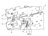
- FIG. 2 a schematic perspective illustration of a detail of the receiving compartment 12 is shown.
- the receiving compartment 12 has a first side wall 20 and a second side wall 22.
- the locking elements 24, 26 are designed in a Y-shaped manner and each have a first leg 28, 30, a second leg 32, 34 as well as a third leg 36, 38.
- the locking elements 24, 26 are each mounted to the side walls 20, 22 rotatably about an axis of rotation 40, 42, the axis of rotation 40, 42 running through the point of intersection of the center axes of the legs 28 to 38.
- one projection 44, 46 each is provided which is guided in a circular ring segment-shaped guide slot 48, 50 of the respective side wall 20, 22.
- a respective first end of a spring 52, 54 is arranged at the projection 44, 46, the respective second end of the respective spring 52, 54 being mounted to the respective side wall 20, 22.
- engagement elements 104 which are in particular designed in the form of small pins contact the second legs 32, 34 of the respective locking elements 24, 26.
- the locking elements 24, 26 are moved against the restoring force of the springs 52, 54 from the unlocked position into a locked position shown in Figure 4 .
- the springs 52, 54 are tensioned further until the projections 44, 46 are arranged at the peaks 58 of the guide slots 48, 50.
- the above-described locking mechanism has the advantage that the locking and unlocking is automatically performed during insertion and removal of the cash box 102. Further, the locking mechanism has the advantage that it is constructed very simply and cost-efficiently. In addition, by way of the knocking of the projections 44, 46 against the ends 56, 60 of the guide slots 48, 50 characteristic clicking sounds occur by which the operator can hear the locking and the unlocking.
Landscapes
- Physics & Mathematics (AREA)
- General Physics & Mathematics (AREA)
- Business, Economics & Management (AREA)
- Accounting & Taxation (AREA)
- Finance (AREA)
- Engineering & Computer Science (AREA)
- Mechanical Engineering (AREA)
- Control Of Vending Devices And Auxiliary Devices For Vending Devices (AREA)
- Financial Or Insurance-Related Operations Such As Payment And Settlement (AREA)
Abstract
Description
- The invention relates to an automated teller machine having at least one receiving compartment for receiving a cash box.
- Known automated teller machines have several receiving compartments, into each of which a cash box can be inserted and again be removed therefrom. For the automatic feeding of notes of value to the cash box or the automatic removal of notes of value from the cash box it is necessary that the cash box is arranged in a precisely predetermined position within the receiving compartment. In order to ensure this, most automated teller machines have locking mechanisms by means of which the cash box is held in the predetermined position in the receiving compartment.
- In the known locking mechanisms, a locking element for locking and/or unlocking the cash box has to be actuated manually. This has the disadvantage that, when a cash box is removed, one hand is required for unlocking so that the cash box can only be handled with one hand, which makes the handling more difficult. In addition, such locking mechanisms are complexly constructed and thus also cost-intensive.
- From document
US 2002/0007771 A1 , an automated teller machine is known in which one retainer each is mounted in front of the cash boxes to prevent their removal. These retainers are attached and removed manually. - Document
US 6,047,998 A describes a mechanism by means of which cash boxes can be locked within an automated teller machine. Here, too, the locking has to be performed actively and is very complexly constructed. - Document
US 2002/0063035 A1 describes a cart for the transport of cash boxes, in which the cash boxes are locked in their receiving compartments via a locking mechanism. - It is the object of the invention to specify an automated teller machine in which the locking and unlocking of the cash boxes in the receiving compartment is accomplished particularly easily and which is constructed simply and cost-efficiently.
- This object is solved by an automated teller machine having the features of claim 1. Advantageous developments of the invention are specified in the dependent claims.
- According to the invention, at least one locking element which is movable between a locked and an unlocked position is provided on a wall of the receiving compartment. Here, the locking element is designed and mounted to the wall such that when a cash box is inserted into the receiving compartment the locking element is automatically moved from the unlocked into the locked position by means of a contact with an engagement element of the cash box.
- In a particularly preferred embodiment, the locking element is also designed and mounted such that when the cash box is removed from the receiving compartment the locking element is automatically moved from the locked position into the unlocked position by means of the contact with the engagement element of the cash box.
- Since the locking and unlocking of the locking mechanism is accomplished automatically by means of the contact with the cash box when the cash box is inserted or removed, it is no longer necessary that a locking mechanism has to be locked or unlocked manually. Thus, a particularly easy handling is possible since the operator can use both hands for the insertion or removal of the cash box. In addition, elements which require a manual operation can be dispensed with so that the locking element and the entire locking mechanism can be constructed particularly easily and thus cost-efficiently. Nevertheless, by means of the automatic locking it is guaranteed that the cash box, when inserted into the receiving compartment, is always arranged in the predetermined position.
- Since the locking mechanism in particular merely serves to guarantee that the cash box is arranged in the predetermined position and does not serve as an anti-removal protection for preventing the unauthorized removal, it is not necessary that it has to be activated actively but the passive activation via the cash box is sufficient and makes the correspondingly simple structure and the easy handling possible.
- In a particularly preferred embodiment, the locking element is designed such that when a cash box has been inserted into the receiving compartment and the locking element is arranged in the locked position, the engagement element of the cash box is received in a receiving area of the locking element such that the cash box cannot be removed from the receiving compartment without the locking element being moved from the locked into the unlocked position during removal.
- On the contrary, the unlocked position is the position of the locking element in which the cash box can be removed without the locking element first having to be changed with respect to its position and in particular without the cash box contacting the locking element at all.
- The locking element is in particular mounted to the wall of the receiving compartment rotatably about an axis of rotation. The locking element is pivoted about this axis of rotation between the locked and the unlocked position by a predetermined angle. Thus, a particularly easy movement of the locking element between the locked and the unlocked position is achieved. In particular, due to this pivot movement only little installation space is required and the entire mechanism can have a simple design.
- Further, it is advantageous when an elastic element is provided which biases the locking element to the locked position when it is arranged in the locked position, and which biases the locking element to the unlocked position when it is arranged in the unlocked position. As a result, it is achieved that the locking element is always biased in its respective position and has to be moved against the restoring force of the elastic element from the respective one position into the respective other position by means of the contact with the engagement element.
- The elastic element is in particular designed as a spring, preferably a screw tension spring, a first end of the spring being mounted to the wall of the receiving compartment and a second end of the spring being mounted to the locking element. Thus, a particularly simple, cost-efficient structure is achieved.
- Further, it is advantageous when a circular ring segment-shaped guide slot is provided in the wall of the receiving compartment and when the locking element has a projection, in particular a boss, which projects into the guide slot so that the locking element, when moved between the locked and the unlocked position, is guided via the engagement of the projection in the guide slot.
- Thus, a safe movement of the locking element between the unlocked and the locked position is achieved. In particular, it is guaranteed via the guide slot that, despite of the biasing by means of the elastic element, the locking element can only move between the locked and the unlocked position and an unintentional movement into a non-defined position is prevented.
- When the locking element is arranged in the unlocked position, then the projection of the locking element is in particular arranged at a first end of the guide slot and in particular contacts a wall of the guide slot which delimits the guide slot in this direction. On the contrary, the projection is arranged at a second end of the guide slot when the locking element is arranged in the locked position and, here too, contacts a wall delimiting the guide slot.
- As a result, on the one hand, the definition of the locked and the unlocked position is achieved easily. On the other hand, the knocking of the projection against the end of the respective guide slot produces a sound, in particular a clicking sound, by which the operator who inserts or removes the cash box is acoustically informed about the fact that the locking mechanism is released or actuated.
- The elastic element is arranged such that when the projection is arranged towards the first end with respect to the peak of the guide slot, i.e. has a smaller angular distance to the first end than to the second end, the elastic element moves the locking element into the unlocked position. When the projection is arranged towards the second end with respect to the peak of the guide slot, i.e. has a smaller angular distance to the second end than to the first end, the elastic element moves the locking element into the locked position. The peak of the guide slot is in particular defined as the point which has the same distance to both ends of the guide slot and has the largest distance to the mounting point of the elastic element via which the elastic element is mounted to the wall.
- As a result, it is easily achieved that the locking element always has to be moved against the force of the elastic element from one position into the other position and is biased by means of the elastic element into its former position until the peak is passed.
- Further, it is advantageous when the peak of the guide slot and the mounting point where the elastic element is mounted to the wall lie on a straight line which intersects the axis of rotation about which the locking element is rotatable. In particular, the axis of rotation, the peak and the mounting point are arranged vertically below one another. As a result, it is achieved that the elastic element, when the projection of the locking element is arranged at the peak, i.e. when the locking element is arranged exactly centrally between the unlocked and the locked position, exerts the highest restoring force onto the locking element and thus, when the locking element is moved out of the central position, always moves the locking element in the direction in which it has been moved from the center.
- The locking element is in particular designed in a Y-shaped manner. Here, the locking element in particular has a first leg, a second leg and a third leg, which are connected to each other by one common connecting area, and wherein the axis of rotation about which the locking element can be rotated runs through the point of intersection of the three legs, in particular the point of intersection of the longitudinal centerline of the legs. Thus, a particularly simple and compact structure is achieved.
- The projection which is guided in the guide slot is in particular provided at the end of the first leg opposite to the point of intersection. In particular, also the elastic element is mounted to the locking element at this end of the first leg opposite to this point of intersection.
- Between the second and the third leg, on the other hand, the receiving area is provided in which the engagement element of the cash box is arranged when the cash box is inserted into the receiving compartment.
- In particular, the engagement element of the cash box presses against the second leg when the cash box is inserted and moves the locking element from the unlocked into the locked position by means of this contact. When, on the other hand, the cash box is removed, the engagement element contacts the third leg of the locking element and moves the locking element from the locked into the unlocked position by means of this contact. As a result, a particularly simple structure and a particularly simple but nevertheless safe functionality is achieved.
- In a particularly preferred embodiment of the invention, a further locking element is arranged on the wall of the receiving compartment, the further locking element being designed and mounted such that when the cash box is inserted into the receiving compartment the further locking element is automatically moved from the unlocked into the locked position by means of the contact with a further engagement element of the cash box and/or when the cash box is removed from the receiving compartment the further locking element is automatically moved from the locked into the unlocked position by means of the contact with the further engagement element.
- The two locking elements are in particular arranged at opposite sides of the receiving compartment.
- The further locking element is preferably formed identically to the afore-described locking element. In particular, also the mounting of the further locking element is designed analogously to the mounting of the one locking element. In particular, the further locking element and the entire mechanism of the further locking element can be developed with the features described above for the one locking element.
- Further, it is advantageous when the automated teller machine comprises at least one further receiving compartment, preferably several further receiving compartments.
- In these receiving compartments, too, in particular one, preferably two locking elements each are arranged, which locking elements are in particular designed and mounted identically to the afore-mentioned locking elements. As a result, it is achieved that in all receiving compartments of the automated teller machine a safe and simple locking of the cash boxes can be accomplished.
- A further aspect of the invention relates to an arrangement comprised of an automated teller machine of the afore-described type and a cash box, the cash box being received in the receiving compartment of the automated teller machine.
- Further features and advantages of the invention result from the following description which describes the invention in more detail on the basis of embodiments in connection with the enclosed Figures.
-
Figure 1 shows a schematic highly simplified illustration of an automated teller machine and three cash boxes. -
Figure 2 shows a schematic perspective illustration of a detail of a receiving compartment of the automated teller machine according toFigure 1 . -
Figure 3 shows a schematic perspective illustration of the receiving compartment according toFigure 2 and a cash box in a first operating state, and -
Figure 4 shows a schematic illustration of the receiving compartment and the cash box according toFigure 3 in a second operating state. - In
Figure 1 , a schematic highly simplified illustration of anarrangement 100 comprised of anautomated teller machine 10 and threecash boxes 102 is shown. Theautomated teller machine 10 has four receivingcompartments 12 to 18, wherein onecash box 102 each is inserted into the receivingcompartments 14 to 18 and no cash box is inserted into the receivingcompartment 12. - The
cash boxes 102 can be removed from the receivingcompartments 12 to 18 and inserted thereinto. For the orderly feeding of notes of value to thecash boxes 102 and the orderly removal of notes of value from thecash boxes 102 it is necessary that these are arranged in predetermined positions within the automated teller machine. - In order to guarantee this predetermined orientation, a locking mechanism described in more detail in connection with
Figures 2 to 4 is provided in each receivingcompartment 12 to 18. This locking mechanism is exemplarily described for the receivingcompartment 12. The other receivingcompartments 14 to 18 are in particular identically formed and in particular have the same locking mechanism. - In
Figure 2 , a schematic perspective illustration of a detail of the receivingcompartment 12 is shown. The receivingcompartment 12 has afirst side wall 20 and asecond side wall 22. At the sides of theside walls cash box 102 is received onelocking element elements first leg second leg third leg - The locking
elements side walls rotation rotation legs 28 to 38. - At the end of the
first leg rotation projection guide slot respective side wall - Further, a respective first end of a
spring projection respective spring respective side wall - When no
cash box 102 is received in the receivingcompartment 12, then the lockingelements Figure 3 . In this unlocked position, theprojections first end 56 of therespective guide slot - When, as shown in
Figure 3 , acash box 102 is inserted into the receivingcompartment 12 in the direction of the arrow P1, thenengagement elements 104 which are in particular designed in the form of small pins contact thesecond legs respective locking elements engagement elements 104 and thesecond legs elements springs Figure 4 . Here, thesprings projections peaks 58 of theguide slots peak 58 is passed, then thespring respective locking element projections guide slots - When the locking
units Figure 4 , then theengagement elements 104 of thecash box 102 are received in the receivingareas 62 arranged between thesecond legs third legs cash box 102 is held in a predetermined position. - When the
cash box 102 is removed, it is moved in the direction of the arrow P2 out of the receiving area, wherein theengagement elements 104 contact thethird legs elements locking elements - The above-described locking mechanism has the advantage that the locking and unlocking is automatically performed during insertion and removal of the
cash box 102. Further, the locking mechanism has the advantage that it is constructed very simply and cost-efficiently. In addition, by way of the knocking of theprojections ends guide slots -
- 10
- automated teller machine
- 12 to 18
- receiving compartment
- 20, 22
- side wall
- 24, 26
- locking element
- 28 to 38
- leg
- 40, 42
- axis of rotation
- 44, 46
- projection
- 48, 50
- guide slot
- 52, 54
- spring
- 56, 60
- end
- 58
- peak
- 62
- receiving area
- 100
- arrangement
- 102
- cash box
- 104
- engagement element
- P1, P2
- direction
Claims (17)
- An automated teller machine,
comprising at least one receiving compartment (12 to 18) for receiving a cash box (102),
characterized in that on a wall (20, 22) of the receiving compartment (12 to 18) at least one locking element (24, 26) is provided which is movable between a locked and an unlocked position, and
that the locking element (24, 26) is designed and mounted such that when a cash box (102) is inserted into the receiving compartment (12 to 18), the locking element (24, 26) is automatically moved from the unlocked into the locked position by means of the contact with an engagement element (104) of the cash box (102). - The automated teller machine (10) according to claim 1, characterized in that the locking element (24, 26) is designed and mounted such that when the cash box (102) is removed from the receiving compartment (12 to 18), the locking element (24, 26) is automatically moved from the locked into the unlocked position by means of the contact with the engagement element (104) of the cash box (10).
- The automated teller machine (10) according to claim 1 or 2, characterized in that the locking element (24, 26) is designed such that when a cash box (102) is inserted into the receiving compartment (12 to 18) the engagement element (24, 26) is received in a receiving area (62) of the locking element (24, 26) being arranged in the locked position such that the cash box (102) cannot be removed from the receiving compartment (12 to 18) without moving the locking element (24, 26) from the locked into the unlocked position during the removal.
- The automated teller machine (10) according to one of the preceding claims, characterized in that the locking element (24, 26) is mounted to the wall of the receiving compartment (20, 22) rotatably about an axis of rotation (40, 42), and that the locking element (24, 26) is pivotable about this axis of rotation (40, 42) between the locked and the unlocked position.
- The automated teller machine (10) according to one of the preceding claims, characterized in that an elastic element (52, 54) is provided which biases the locking element (24, 26) to the locked position when it is arranged in the locked position and which biases the locking element (24, 26) to the unlocked position when it is arranged in the unlocked position.
- The automated teller machine (10) according to claim 5, characterized in that the elastic element (52, 54) comprises a spring, in particular a screw tension spring, one end of which being mounted to the wall (20, 22) and the other end of which being mounted to the locking element (24, 26).
- The automated teller machine (10) according to one of the preceding claims, characterized in that in the wall (20, 22) a circular ring segment-shaped guide slot (48, 50) is provided, that the locking element (24, 26) comprises a projection (44, 46), that the projection (44, 46) is guided in the guide slot (48, 50) and that by means of the engagement of the projection (44, 46) in the guide slot (48, 50) the locking element (24, 26) is guided during the movement between the locked and the unlocked position.
- The automated teller machine (10) according to claim 7, characterized in that when the locking element (24, 26) is arranged in the unlocked position, the projection (44, 46) is arranged at a first end of the guide slot (48, 50) and that when the locking element (24, 26) is arranged in the locked position, the projection (44, 46) is arranged at a second end of the guide slot (48, 50).
- The automated teller machine (10) according to claim 8, characterized in that the elastic element (52, 54) is arranged such that when the projection (44, 46) is arranged towards the first end with respect to the peak 58 of the guide slot (48, 50) the elastic element (52, 54) moves the locking element (24, 26) into the unlocked position and when the projection (44, 46) is arranged towards the second end with respect to the peak (58) of the guide slot (48,50) the elastic element (52, 54) moves the locking element (24, 26) into the locked position.
- The automated teller machine (10) according to claim 8 or 9, characterized in that the peak (58) of the guide slot (48, 50) and the mounting point at which the elastic element (48, 50) is mounted to the wall (20, 22) lie on a straight line and that the axis of rotation (40, 42) about which the locking element (24, 26) is rotatable intersects this straight line.
- The automated teller machine (10) according to one of the preceding claims, characterized in that the locking element (24, 26) is Y-shaped.
- The automated teller machine (10) according to one of the preceding claims, characterized in that the locking element (24, 26) comprises a first leg (28, 30), a second leg (32, 34) and a third leg (36, 38), and that the locking element (24, 26) is mounted to the wall (20, 22) rotatably about an area of intersection of these three legs (28 to 38).
- The automated teller machine (10) according to claim 12, characterized in that the projection (44, 46) which is guided in the guide slot (48, 50) is provided at the end of the first leg (28, 30) opposite to the area of intersection, and/or that the elastic element (52, 54) is mounted to the first leg (28, 30) at the end thereof that is opposite to the area of intersection.
- The automated teller machine (10) according to claim 12 or 13, characterized in that the receiving area (62) in which the engagement element (104) of the cash box (102) is received when the cash box (102) is inserted into the receiving compartment (12 to 18) is arranged between the second and the third leg (32 to 38).
- The automated teller machine (10) according to one of the preceding claims, characterized in that on the wall (20, 22) of the receiving compartment (12 to 18) a further locking element (24, 26) is arranged and that the further locking element (24, 26) is designed and mounted such that when a cash box (102) is inserted into the receiving compartment (12 to 18) the further locking element (24, 26) is automatically moved from the unlocked into the locked position by means of the contact with a further engagement element (104) of the cash box (102).
- The automated teller machine (10) according to claim 15, characterized in that the two locking elements (24, 26) are formed identically.
- An arrangement (100)
comprising an automated teller machine (10) according to one of the claims 1 to 16, and
comprising a cash box (102),
the cash box (102) being received in the receiving compartment (12 to 18) of the automated teller machine (10).
Priority Applications (2)
| Application Number | Priority Date | Filing Date | Title |
|---|---|---|---|
| EP15168190.5A EP3096301B1 (en) | 2015-05-19 | 2015-05-19 | Automated teller machine with an automatically actuatable locking element for locking cash boxes received in receiving compartments in these receiving compartments |
| US15/157,433 US9745779B2 (en) | 2015-05-19 | 2016-05-18 | Automated teller machine with an automatically actuatable locking element for locking cash boxes received in receiving compartments in these receiving compartments |
Applications Claiming Priority (1)
| Application Number | Priority Date | Filing Date | Title |
|---|---|---|---|
| EP15168190.5A EP3096301B1 (en) | 2015-05-19 | 2015-05-19 | Automated teller machine with an automatically actuatable locking element for locking cash boxes received in receiving compartments in these receiving compartments |
Publications (2)
| Publication Number | Publication Date |
|---|---|
| EP3096301A1 true EP3096301A1 (en) | 2016-11-23 |
| EP3096301B1 EP3096301B1 (en) | 2020-01-01 |
Family
ID=53180631
Family Applications (1)
| Application Number | Title | Priority Date | Filing Date |
|---|---|---|---|
| EP15168190.5A Active EP3096301B1 (en) | 2015-05-19 | 2015-05-19 | Automated teller machine with an automatically actuatable locking element for locking cash boxes received in receiving compartments in these receiving compartments |
Country Status (2)
| Country | Link |
|---|---|
| US (1) | US9745779B2 (en) |
| EP (1) | EP3096301B1 (en) |
Citations (5)
| Publication number | Priority date | Publication date | Assignee | Title |
|---|---|---|---|---|
| GB1117071A (en) * | 1966-02-21 | 1968-06-12 | G K N Sankey Proprietary Ltd | Improvements in or relating to drawers and cabinet assemblies |
| US6047998A (en) | 1998-02-03 | 2000-04-11 | Mas-Hamilton Group, Inc. | Cassette and cassette rack locking device |
| US20020007771A1 (en) | 2000-04-17 | 2002-01-24 | Michael Braddock | Security system |
| US20020063035A1 (en) | 1997-03-26 | 2002-05-30 | Blad Steven J. | Currency container tracking system and a currency container for use therewith |
| WO2013052348A1 (en) * | 2011-09-28 | 2013-04-11 | Diebold, Incorporated | Automated banking machine operated responsive to data bearing records with improved security |
Family Cites Families (3)
| Publication number | Priority date | Publication date | Assignee | Title |
|---|---|---|---|---|
| GB231239A (en) * | 1923-12-29 | 1925-03-30 | Arthur Warren | Improvements in or relating to treasury note cabinets |
| GB1175151A (en) * | 1966-02-21 | 1969-12-23 | G K N Sankey | Improved filing cabinet. |
| GB2456586B (en) * | 2008-02-01 | 2009-12-16 | Scotia Safes Ltd | Security system and apparatus |
-
2015
- 2015-05-19 EP EP15168190.5A patent/EP3096301B1/en active Active
-
2016
- 2016-05-18 US US15/157,433 patent/US9745779B2/en active Active
Patent Citations (5)
| Publication number | Priority date | Publication date | Assignee | Title |
|---|---|---|---|---|
| GB1117071A (en) * | 1966-02-21 | 1968-06-12 | G K N Sankey Proprietary Ltd | Improvements in or relating to drawers and cabinet assemblies |
| US20020063035A1 (en) | 1997-03-26 | 2002-05-30 | Blad Steven J. | Currency container tracking system and a currency container for use therewith |
| US6047998A (en) | 1998-02-03 | 2000-04-11 | Mas-Hamilton Group, Inc. | Cassette and cassette rack locking device |
| US20020007771A1 (en) | 2000-04-17 | 2002-01-24 | Michael Braddock | Security system |
| WO2013052348A1 (en) * | 2011-09-28 | 2013-04-11 | Diebold, Incorporated | Automated banking machine operated responsive to data bearing records with improved security |
Also Published As
| Publication number | Publication date |
|---|---|
| US20160340933A1 (en) | 2016-11-24 |
| US9745779B2 (en) | 2017-08-29 |
| EP3096301B1 (en) | 2020-01-01 |
Similar Documents
| Publication | Publication Date | Title |
|---|---|---|
| TWI709465B (en) | Handle extension structure and electronic device casing | |
| CN105744924B (en) | Medicine supply unit | |
| US9096980B2 (en) | Snowblower chute control devices, systems, and methods | |
| US20160195366A1 (en) | Firearm associated electronic device with acceleration resistant latch | |
| EP3567994B1 (en) | Slide rail assembly and slide rail kit thereof | |
| TW201128576A (en) | Document handler having validator detachably attached thereto | |
| WO2001005682A1 (en) | Security case | |
| US20090139145A1 (en) | Door and rack | |
| JP2019144298A (en) | Optical transceiver | |
| US8887986B2 (en) | Container for receiving vouchers and method for closing container having a housing part and a cover for receiving vouchers | |
| JP5365534B2 (en) | Storage device and storage system including the same | |
| EP3096301B1 (en) | Automated teller machine with an automatically actuatable locking element for locking cash boxes received in receiving compartments in these receiving compartments | |
| CN109509653B (en) | Switching device and associated switch | |
| CN106023474A (en) | Safe bag module having a handle with one-sided torque transmission | |
| JP2024138779A (en) | Banknote Processing Device | |
| US10210692B2 (en) | Coin storage cassette | |
| US11378996B2 (en) | Operating device | |
| JP4505814B2 (en) | Lock / unlock device | |
| CN105236165A (en) | Paper feed tray | |
| KR200441993Y1 (en) | Cradle Draw-In Device of Crane Breaker | |
| JP2011152825A (en) | Separating device for mobile object | |
| CN105556579B (en) | Cash drawer with blocking element for preventing unintentional movement of the pressurized unit | |
| CA2364865C (en) | Banknote cassete with foldable handle | |
| JP6644582B2 (en) | Medical pump | |
| EP2242238A1 (en) | Mobile terminal apparatus |
Legal Events
| Date | Code | Title | Description |
|---|---|---|---|
| PUAI | Public reference made under article 153(3) epc to a published international application that has entered the european phase |
Free format text: ORIGINAL CODE: 0009012 |
|
| AK | Designated contracting states |
Kind code of ref document: A1 Designated state(s): AL AT BE BG CH CY CZ DE DK EE ES FI FR GB GR HR HU IE IS IT LI LT LU LV MC MK MT NL NO PL PT RO RS SE SI SK SM TR |
|
| AX | Request for extension of the european patent |
Extension state: BA ME |
|
| STAA | Information on the status of an ep patent application or granted ep patent |
Free format text: STATUS: REQUEST FOR EXAMINATION WAS MADE |
|
| 17P | Request for examination filed |
Effective date: 20170517 |
|
| RBV | Designated contracting states (corrected) |
Designated state(s): AL AT BE BG CH CY CZ DE DK EE ES FI FR GB GR HR HU IE IS IT LI LT LU LV MC MK MT NL NO PL PT RO RS SE SI SK SM TR |
|
| STAA | Information on the status of an ep patent application or granted ep patent |
Free format text: STATUS: EXAMINATION IS IN PROGRESS |
|
| 17Q | First examination report despatched |
Effective date: 20180914 |
|
| GRAP | Despatch of communication of intention to grant a patent |
Free format text: ORIGINAL CODE: EPIDOSNIGR1 |
|
| STAA | Information on the status of an ep patent application or granted ep patent |
Free format text: STATUS: GRANT OF PATENT IS INTENDED |
|
| RIC1 | Information provided on ipc code assigned before grant |
Ipc: G07F 19/00 20060101AFI20190711BHEP |
|
| INTG | Intention to grant announced |
Effective date: 20190805 |
|
| GRAS | Grant fee paid |
Free format text: ORIGINAL CODE: EPIDOSNIGR3 |
|
| GRAA | (expected) grant |
Free format text: ORIGINAL CODE: 0009210 |
|
| STAA | Information on the status of an ep patent application or granted ep patent |
Free format text: STATUS: THE PATENT HAS BEEN GRANTED |
|
| AK | Designated contracting states |
Kind code of ref document: B1 Designated state(s): AL AT BE BG CH CY CZ DE DK EE ES FI FR GB GR HR HU IE IS IT LI LT LU LV MC MK MT NL NO PL PT RO RS SE SI SK SM TR |
|
| REG | Reference to a national code |
Ref country code: GB Ref legal event code: FG4D |
|
| REG | Reference to a national code |
Ref country code: CH Ref legal event code: EP Ref country code: AT Ref legal event code: REF Ref document number: 1220771 Country of ref document: AT Kind code of ref document: T Effective date: 20200115 |
|
| REG | Reference to a national code |
Ref country code: DE Ref legal event code: R096 Ref document number: 602015044520 Country of ref document: DE |
|
| REG | Reference to a national code |
Ref country code: IE Ref legal event code: FG4D |
|
| REG | Reference to a national code |
Ref country code: NL Ref legal event code: MP Effective date: 20200101 |
|
| REG | Reference to a national code |
Ref country code: LT Ref legal event code: MG4D |
|
| PG25 | Lapsed in a contracting state [announced via postgrant information from national office to epo] |
Ref country code: NO Free format text: LAPSE BECAUSE OF FAILURE TO SUBMIT A TRANSLATION OF THE DESCRIPTION OR TO PAY THE FEE WITHIN THE PRESCRIBED TIME-LIMIT Effective date: 20200401 Ref country code: RS Free format text: LAPSE BECAUSE OF FAILURE TO SUBMIT A TRANSLATION OF THE DESCRIPTION OR TO PAY THE FEE WITHIN THE PRESCRIBED TIME-LIMIT Effective date: 20200101 Ref country code: FI Free format text: LAPSE BECAUSE OF FAILURE TO SUBMIT A TRANSLATION OF THE DESCRIPTION OR TO PAY THE FEE WITHIN THE PRESCRIBED TIME-LIMIT Effective date: 20200101 Ref country code: LT Free format text: LAPSE BECAUSE OF FAILURE TO SUBMIT A TRANSLATION OF THE DESCRIPTION OR TO PAY THE FEE WITHIN THE PRESCRIBED TIME-LIMIT Effective date: 20200101 Ref country code: NL Free format text: LAPSE BECAUSE OF FAILURE TO SUBMIT A TRANSLATION OF THE DESCRIPTION OR TO PAY THE FEE WITHIN THE PRESCRIBED TIME-LIMIT Effective date: 20200101 Ref country code: CZ Free format text: LAPSE BECAUSE OF FAILURE TO SUBMIT A TRANSLATION OF THE DESCRIPTION OR TO PAY THE FEE WITHIN THE PRESCRIBED TIME-LIMIT Effective date: 20200101 Ref country code: PT Free format text: LAPSE BECAUSE OF FAILURE TO SUBMIT A TRANSLATION OF THE DESCRIPTION OR TO PAY THE FEE WITHIN THE PRESCRIBED TIME-LIMIT Effective date: 20200527 |
|
| PG25 | Lapsed in a contracting state [announced via postgrant information from national office to epo] |
Ref country code: HR Free format text: LAPSE BECAUSE OF FAILURE TO SUBMIT A TRANSLATION OF THE DESCRIPTION OR TO PAY THE FEE WITHIN THE PRESCRIBED TIME-LIMIT Effective date: 20200101 Ref country code: GR Free format text: LAPSE BECAUSE OF FAILURE TO SUBMIT A TRANSLATION OF THE DESCRIPTION OR TO PAY THE FEE WITHIN THE PRESCRIBED TIME-LIMIT Effective date: 20200402 Ref country code: BG Free format text: LAPSE BECAUSE OF FAILURE TO SUBMIT A TRANSLATION OF THE DESCRIPTION OR TO PAY THE FEE WITHIN THE PRESCRIBED TIME-LIMIT Effective date: 20200401 Ref country code: LV Free format text: LAPSE BECAUSE OF FAILURE TO SUBMIT A TRANSLATION OF THE DESCRIPTION OR TO PAY THE FEE WITHIN THE PRESCRIBED TIME-LIMIT Effective date: 20200101 Ref country code: SE Free format text: LAPSE BECAUSE OF FAILURE TO SUBMIT A TRANSLATION OF THE DESCRIPTION OR TO PAY THE FEE WITHIN THE PRESCRIBED TIME-LIMIT Effective date: 20200101 Ref country code: IS Free format text: LAPSE BECAUSE OF FAILURE TO SUBMIT A TRANSLATION OF THE DESCRIPTION OR TO PAY THE FEE WITHIN THE PRESCRIBED TIME-LIMIT Effective date: 20200501 |
|
| REG | Reference to a national code |
Ref country code: DE Ref legal event code: R097 Ref document number: 602015044520 Country of ref document: DE |
|
| PG25 | Lapsed in a contracting state [announced via postgrant information from national office to epo] |
Ref country code: RO Free format text: LAPSE BECAUSE OF FAILURE TO SUBMIT A TRANSLATION OF THE DESCRIPTION OR TO PAY THE FEE WITHIN THE PRESCRIBED TIME-LIMIT Effective date: 20200101 Ref country code: SK Free format text: LAPSE BECAUSE OF FAILURE TO SUBMIT A TRANSLATION OF THE DESCRIPTION OR TO PAY THE FEE WITHIN THE PRESCRIBED TIME-LIMIT Effective date: 20200101 Ref country code: DK Free format text: LAPSE BECAUSE OF FAILURE TO SUBMIT A TRANSLATION OF THE DESCRIPTION OR TO PAY THE FEE WITHIN THE PRESCRIBED TIME-LIMIT Effective date: 20200101 Ref country code: ES Free format text: LAPSE BECAUSE OF FAILURE TO SUBMIT A TRANSLATION OF THE DESCRIPTION OR TO PAY THE FEE WITHIN THE PRESCRIBED TIME-LIMIT Effective date: 20200101 Ref country code: SM Free format text: LAPSE BECAUSE OF FAILURE TO SUBMIT A TRANSLATION OF THE DESCRIPTION OR TO PAY THE FEE WITHIN THE PRESCRIBED TIME-LIMIT Effective date: 20200101 Ref country code: EE Free format text: LAPSE BECAUSE OF FAILURE TO SUBMIT A TRANSLATION OF THE DESCRIPTION OR TO PAY THE FEE WITHIN THE PRESCRIBED TIME-LIMIT Effective date: 20200101 |
|
| PLBE | No opposition filed within time limit |
Free format text: ORIGINAL CODE: 0009261 |
|
| STAA | Information on the status of an ep patent application or granted ep patent |
Free format text: STATUS: NO OPPOSITION FILED WITHIN TIME LIMIT |
|
| REG | Reference to a national code |
Ref country code: AT Ref legal event code: MK05 Ref document number: 1220771 Country of ref document: AT Kind code of ref document: T Effective date: 20200101 |
|
| 26N | No opposition filed |
Effective date: 20201002 |
|
| PG25 | Lapsed in a contracting state [announced via postgrant information from national office to epo] |
Ref country code: LI Free format text: LAPSE BECAUSE OF NON-PAYMENT OF DUE FEES Effective date: 20200531 Ref country code: AT Free format text: LAPSE BECAUSE OF FAILURE TO SUBMIT A TRANSLATION OF THE DESCRIPTION OR TO PAY THE FEE WITHIN THE PRESCRIBED TIME-LIMIT Effective date: 20200101 Ref country code: MC Free format text: LAPSE BECAUSE OF FAILURE TO SUBMIT A TRANSLATION OF THE DESCRIPTION OR TO PAY THE FEE WITHIN THE PRESCRIBED TIME-LIMIT Effective date: 20200101 Ref country code: IT Free format text: LAPSE BECAUSE OF FAILURE TO SUBMIT A TRANSLATION OF THE DESCRIPTION OR TO PAY THE FEE WITHIN THE PRESCRIBED TIME-LIMIT Effective date: 20200101 Ref country code: CH Free format text: LAPSE BECAUSE OF NON-PAYMENT OF DUE FEES Effective date: 20200531 |
|
| PG25 | Lapsed in a contracting state [announced via postgrant information from national office to epo] |
Ref country code: PL Free format text: LAPSE BECAUSE OF FAILURE TO SUBMIT A TRANSLATION OF THE DESCRIPTION OR TO PAY THE FEE WITHIN THE PRESCRIBED TIME-LIMIT Effective date: 20200101 Ref country code: SI Free format text: LAPSE BECAUSE OF FAILURE TO SUBMIT A TRANSLATION OF THE DESCRIPTION OR TO PAY THE FEE WITHIN THE PRESCRIBED TIME-LIMIT Effective date: 20200101 |
|
| REG | Reference to a national code |
Ref country code: BE Ref legal event code: MM Effective date: 20200531 |
|
| PG25 | Lapsed in a contracting state [announced via postgrant information from national office to epo] |
Ref country code: LU Free format text: LAPSE BECAUSE OF NON-PAYMENT OF DUE FEES Effective date: 20200519 |
|
| PG25 | Lapsed in a contracting state [announced via postgrant information from national office to epo] |
Ref country code: IE Free format text: LAPSE BECAUSE OF NON-PAYMENT OF DUE FEES Effective date: 20200519 |
|
| PG25 | Lapsed in a contracting state [announced via postgrant information from national office to epo] |
Ref country code: BE Free format text: LAPSE BECAUSE OF NON-PAYMENT OF DUE FEES Effective date: 20200531 |
|
| REG | Reference to a national code |
Ref country code: FR Ref legal event code: PLFP Year of fee payment: 8 |
|
| PG25 | Lapsed in a contracting state [announced via postgrant information from national office to epo] |
Ref country code: TR Free format text: LAPSE BECAUSE OF FAILURE TO SUBMIT A TRANSLATION OF THE DESCRIPTION OR TO PAY THE FEE WITHIN THE PRESCRIBED TIME-LIMIT Effective date: 20200101 Ref country code: MT Free format text: LAPSE BECAUSE OF FAILURE TO SUBMIT A TRANSLATION OF THE DESCRIPTION OR TO PAY THE FEE WITHIN THE PRESCRIBED TIME-LIMIT Effective date: 20200101 Ref country code: CY Free format text: LAPSE BECAUSE OF FAILURE TO SUBMIT A TRANSLATION OF THE DESCRIPTION OR TO PAY THE FEE WITHIN THE PRESCRIBED TIME-LIMIT Effective date: 20200101 |
|
| PG25 | Lapsed in a contracting state [announced via postgrant information from national office to epo] |
Ref country code: MK Free format text: LAPSE BECAUSE OF FAILURE TO SUBMIT A TRANSLATION OF THE DESCRIPTION OR TO PAY THE FEE WITHIN THE PRESCRIBED TIME-LIMIT Effective date: 20200101 Ref country code: AL Free format text: LAPSE BECAUSE OF FAILURE TO SUBMIT A TRANSLATION OF THE DESCRIPTION OR TO PAY THE FEE WITHIN THE PRESCRIBED TIME-LIMIT Effective date: 20200101 |
|
| REG | Reference to a national code |
Ref country code: GB Ref legal event code: 732E Free format text: REGISTERED BETWEEN 20230323 AND 20230329 |
|
| REG | Reference to a national code |
Ref country code: GB Ref legal event code: 732E Free format text: REGISTERED BETWEEN 20230525 AND 20230601 |
|
| REG | Reference to a national code |
Ref country code: DE Ref legal event code: R081 Ref document number: 602015044520 Country of ref document: DE Owner name: DIEBOLD NIXDORF SYSTEMS GMBH, DE Free format text: FORMER OWNER: WINCOR NIXDORF INTERNATIONAL GMBH, 33106 PADERBORN, DE |
|
| PGFP | Annual fee paid to national office [announced via postgrant information from national office to epo] |
Ref country code: DE Payment date: 20250423 Year of fee payment: 11 |
|
| PGFP | Annual fee paid to national office [announced via postgrant information from national office to epo] |
Ref country code: GB Payment date: 20250423 Year of fee payment: 11 |
|
| PGFP | Annual fee paid to national office [announced via postgrant information from national office to epo] |
Ref country code: FR Payment date: 20250423 Year of fee payment: 11 |