EP3096051A1 - Valve device - Google Patents
Valve device Download PDFInfo
- Publication number
- EP3096051A1 EP3096051A1 EP14875065.6A EP14875065A EP3096051A1 EP 3096051 A1 EP3096051 A1 EP 3096051A1 EP 14875065 A EP14875065 A EP 14875065A EP 3096051 A1 EP3096051 A1 EP 3096051A1
- Authority
- EP
- European Patent Office
- Prior art keywords
- diaphragm
- valve
- outlet port
- port
- valve seat
- Prior art date
- Legal status (The legal status is an assumption and is not a legal conclusion. Google has not performed a legal analysis and makes no representation as to the accuracy of the status listed.)
- Withdrawn
Links
Images




Classifications
-
- F—MECHANICAL ENGINEERING; LIGHTING; HEATING; WEAPONS; BLASTING
- F16—ENGINEERING ELEMENTS AND UNITS; GENERAL MEASURES FOR PRODUCING AND MAINTAINING EFFECTIVE FUNCTIONING OF MACHINES OR INSTALLATIONS; THERMAL INSULATION IN GENERAL
- F16K—VALVES; TAPS; COCKS; ACTUATING-FLOATS; DEVICES FOR VENTING OR AERATING
- F16K11/00—Multiple-way valves, e.g. mixing valves; Pipe fittings incorporating such valves
- F16K11/02—Multiple-way valves, e.g. mixing valves; Pipe fittings incorporating such valves with all movable sealing faces moving as one unit
- F16K11/04—Multiple-way valves, e.g. mixing valves; Pipe fittings incorporating such valves with all movable sealing faces moving as one unit comprising only lift valves
- F16K11/052—Multiple-way valves, e.g. mixing valves; Pipe fittings incorporating such valves with all movable sealing faces moving as one unit comprising only lift valves with pivoted closure members, e.g. butterfly valves
- F16K11/0525—Multiple-way valves, e.g. mixing valves; Pipe fittings incorporating such valves with all movable sealing faces moving as one unit comprising only lift valves with pivoted closure members, e.g. butterfly valves the closure members being pivoted around an essentially central axis
-
- B—PERFORMING OPERATIONS; TRANSPORTING
- B01—PHYSICAL OR CHEMICAL PROCESSES OR APPARATUS IN GENERAL
- B01L—CHEMICAL OR PHYSICAL LABORATORY APPARATUS FOR GENERAL USE
- B01L3/00—Containers or dishes for laboratory use, e.g. laboratory glassware; Droppers
- B01L3/56—Labware specially adapted for transferring fluids
- B01L3/567—Valves, taps or stop-cocks
-
- F—MECHANICAL ENGINEERING; LIGHTING; HEATING; WEAPONS; BLASTING
- F16—ENGINEERING ELEMENTS AND UNITS; GENERAL MEASURES FOR PRODUCING AND MAINTAINING EFFECTIVE FUNCTIONING OF MACHINES OR INSTALLATIONS; THERMAL INSULATION IN GENERAL
- F16K—VALVES; TAPS; COCKS; ACTUATING-FLOATS; DEVICES FOR VENTING OR AERATING
- F16K11/00—Multiple-way valves, e.g. mixing valves; Pipe fittings incorporating such valves
- F16K11/02—Multiple-way valves, e.g. mixing valves; Pipe fittings incorporating such valves with all movable sealing faces moving as one unit
- F16K11/022—Multiple-way valves, e.g. mixing valves; Pipe fittings incorporating such valves with all movable sealing faces moving as one unit comprising a deformable member
-
- F—MECHANICAL ENGINEERING; LIGHTING; HEATING; WEAPONS; BLASTING
- F16—ENGINEERING ELEMENTS AND UNITS; GENERAL MEASURES FOR PRODUCING AND MAINTAINING EFFECTIVE FUNCTIONING OF MACHINES OR INSTALLATIONS; THERMAL INSULATION IN GENERAL
- F16K—VALVES; TAPS; COCKS; ACTUATING-FLOATS; DEVICES FOR VENTING OR AERATING
- F16K11/00—Multiple-way valves, e.g. mixing valves; Pipe fittings incorporating such valves
- F16K11/02—Multiple-way valves, e.g. mixing valves; Pipe fittings incorporating such valves with all movable sealing faces moving as one unit
- F16K11/04—Multiple-way valves, e.g. mixing valves; Pipe fittings incorporating such valves with all movable sealing faces moving as one unit comprising only lift valves
- F16K11/052—Multiple-way valves, e.g. mixing valves; Pipe fittings incorporating such valves with all movable sealing faces moving as one unit comprising only lift valves with pivoted closure members, e.g. butterfly valves
-
- F—MECHANICAL ENGINEERING; LIGHTING; HEATING; WEAPONS; BLASTING
- F16—ENGINEERING ELEMENTS AND UNITS; GENERAL MEASURES FOR PRODUCING AND MAINTAINING EFFECTIVE FUNCTIONING OF MACHINES OR INSTALLATIONS; THERMAL INSULATION IN GENERAL
- F16K—VALVES; TAPS; COCKS; ACTUATING-FLOATS; DEVICES FOR VENTING OR AERATING
- F16K25/00—Details relating to contact between valve members and seats
- F16K25/005—Particular materials for seats or closure elements
-
- F—MECHANICAL ENGINEERING; LIGHTING; HEATING; WEAPONS; BLASTING
- F16—ENGINEERING ELEMENTS AND UNITS; GENERAL MEASURES FOR PRODUCING AND MAINTAINING EFFECTIVE FUNCTIONING OF MACHINES OR INSTALLATIONS; THERMAL INSULATION IN GENERAL
- F16K—VALVES; TAPS; COCKS; ACTUATING-FLOATS; DEVICES FOR VENTING OR AERATING
- F16K31/00—Actuating devices; Operating means; Releasing devices
- F16K31/02—Actuating devices; Operating means; Releasing devices electric; magnetic
- F16K31/06—Actuating devices; Operating means; Releasing devices electric; magnetic using a magnet, e.g. diaphragm valves, cutting off by means of a liquid
- F16K31/0603—Multiple-way valves
- F16K31/0641—Multiple-way valves the valve member being a diaphragm
-
- F—MECHANICAL ENGINEERING; LIGHTING; HEATING; WEAPONS; BLASTING
- F16—ENGINEERING ELEMENTS AND UNITS; GENERAL MEASURES FOR PRODUCING AND MAINTAINING EFFECTIVE FUNCTIONING OF MACHINES OR INSTALLATIONS; THERMAL INSULATION IN GENERAL
- F16K—VALVES; TAPS; COCKS; ACTUATING-FLOATS; DEVICES FOR VENTING OR AERATING
- F16K31/00—Actuating devices; Operating means; Releasing devices
- F16K31/02—Actuating devices; Operating means; Releasing devices electric; magnetic
- F16K31/06—Actuating devices; Operating means; Releasing devices electric; magnetic using a magnet, e.g. diaphragm valves, cutting off by means of a liquid
- F16K31/10—Actuating devices; Operating means; Releasing devices electric; magnetic using a magnet, e.g. diaphragm valves, cutting off by means of a liquid with additional mechanism between armature and closure member
-
- F—MECHANICAL ENGINEERING; LIGHTING; HEATING; WEAPONS; BLASTING
- F16—ENGINEERING ELEMENTS AND UNITS; GENERAL MEASURES FOR PRODUCING AND MAINTAINING EFFECTIVE FUNCTIONING OF MACHINES OR INSTALLATIONS; THERMAL INSULATION IN GENERAL
- F16K—VALVES; TAPS; COCKS; ACTUATING-FLOATS; DEVICES FOR VENTING OR AERATING
- F16K31/00—Actuating devices; Operating means; Releasing devices
- F16K31/02—Actuating devices; Operating means; Releasing devices electric; magnetic
- F16K31/06—Actuating devices; Operating means; Releasing devices electric; magnetic using a magnet, e.g. diaphragm valves, cutting off by means of a liquid
- F16K31/10—Actuating devices; Operating means; Releasing devices electric; magnetic using a magnet, e.g. diaphragm valves, cutting off by means of a liquid with additional mechanism between armature and closure member
- F16K31/105—Actuating devices; Operating means; Releasing devices electric; magnetic using a magnet, e.g. diaphragm valves, cutting off by means of a liquid with additional mechanism between armature and closure member for rotating valves
-
- F—MECHANICAL ENGINEERING; LIGHTING; HEATING; WEAPONS; BLASTING
- F16—ENGINEERING ELEMENTS AND UNITS; GENERAL MEASURES FOR PRODUCING AND MAINTAINING EFFECTIVE FUNCTIONING OF MACHINES OR INSTALLATIONS; THERMAL INSULATION IN GENERAL
- F16K—VALVES; TAPS; COCKS; ACTUATING-FLOATS; DEVICES FOR VENTING OR AERATING
- F16K7/00—Diaphragm valves or cut-off apparatus, e.g. with a member deformed, but not moved bodily, to close the passage ; Pinch valves
- F16K7/12—Diaphragm valves or cut-off apparatus, e.g. with a member deformed, but not moved bodily, to close the passage ; Pinch valves with flat, dished, or bowl-shaped diaphragm
- F16K7/14—Diaphragm valves or cut-off apparatus, e.g. with a member deformed, but not moved bodily, to close the passage ; Pinch valves with flat, dished, or bowl-shaped diaphragm arranged to be deformed against a flat seat
-
- B—PERFORMING OPERATIONS; TRANSPORTING
- B01—PHYSICAL OR CHEMICAL PROCESSES OR APPARATUS IN GENERAL
- B01L—CHEMICAL OR PHYSICAL LABORATORY APPARATUS FOR GENERAL USE
- B01L2300/00—Additional constructional details
- B01L2300/12—Specific details about materials
- B01L2300/123—Flexible; Elastomeric
-
- B—PERFORMING OPERATIONS; TRANSPORTING
- B01—PHYSICAL OR CHEMICAL PROCESSES OR APPARATUS IN GENERAL
- B01L—CHEMICAL OR PHYSICAL LABORATORY APPARATUS FOR GENERAL USE
- B01L2400/00—Moving or stopping fluids
- B01L2400/06—Valves, specific forms thereof
- B01L2400/0622—Valves, specific forms thereof distribution valves, valves having multiple inlets and/or outlets, e.g. metering valves, multi-way valves
-
- B—PERFORMING OPERATIONS; TRANSPORTING
- B01—PHYSICAL OR CHEMICAL PROCESSES OR APPARATUS IN GENERAL
- B01L—CHEMICAL OR PHYSICAL LABORATORY APPARATUS FOR GENERAL USE
- B01L2400/00—Moving or stopping fluids
- B01L2400/06—Valves, specific forms thereof
- B01L2400/0633—Valves, specific forms thereof with moving parts
- B01L2400/0638—Valves, specific forms thereof with moving parts membrane valves, flap valves
-
- Y—GENERAL TAGGING OF NEW TECHNOLOGICAL DEVELOPMENTS; GENERAL TAGGING OF CROSS-SECTIONAL TECHNOLOGIES SPANNING OVER SEVERAL SECTIONS OF THE IPC; TECHNICAL SUBJECTS COVERED BY FORMER USPC CROSS-REFERENCE ART COLLECTIONS [XRACs] AND DIGESTS
- Y10—TECHNICAL SUBJECTS COVERED BY FORMER USPC
- Y10T—TECHNICAL SUBJECTS COVERED BY FORMER US CLASSIFICATION
- Y10T137/00—Fluid handling
- Y10T137/8593—Systems
- Y10T137/86493—Multi-way valve unit
- Y10T137/86501—Sequential distributor or collector type
Definitions
- the present invention relates to a valve device to be used in various analyzing devices such as chemical testing devices, environmental analyzing devices and biotechnology research devices.
- valve device for controlling a flow rate of a fluid used in the measurement is required to be further improved in its performance.
- a diaphragm made of a rubber material or the like having elasticity is employed as a valve opening/closing mechanism in order to realize excellent chemical resistance.
- the diaphragm forms a bulkhead that divides a valve chest, and receives an external driving force to switch fluid passages.
- valve device in order to precisely control the flow rate of the fluid, it is necessary to improve the sealing capability of the diaphragm at the time of closing of a port.
- the sealing capability of the diaphragm at the time of closing the port can be improved by increasing the load for pressing the diaphragm when seating the diaphragm on a valve seat formed around the opening of the port, i.e., the pressure of the diaphragm on the valve seat when seated.
- Patent Document 1 discloses a valve mechanism of a valve device whose diaphragm is driven by a solenoid, a first spring member, a second spring member and the like, in which the resilient force (spring force) of the second spring member is set to be twice the resilient force of the first spring member.
- Patent Document 1 Japanese Unexamined Patent Publication No. 2000-297876
- a main object is to provide a valve device in which both of the diaphragm's sealing capability and durability can be achieved, while reducing the size.
- the present invention is a valve device having a valve main body defining a valve chest having at least one port through which fluid flows, a valve for opening and closing the port, and a drive means for driving the valve to open and close the port, the port having an opening around which a valve seat is formed, the valve disposed so as to cover the valve chest and having a diaphragm for seating on or separating from the valve seat to open and close the port, characterized in that the diaphragm is made of an elastic material whose durometer A hardness in JIS-K6253 is A50 to A85, and the pressure of the diaphragm on the valve seat when seated is 0.5 to 1.0 N/sq.mm.
- the durometer A hardness in JIS-K6253 of the diaphragm is A60 to A80.
- the diaphragm includes, as a rubber component, at least one kind of ethylene-propylene-diene, fluorinated rubber, hydrogenated nitrile rubber, butylene rubber and silicone rubber.
- the diaphragm includes, as fillers, at least one kind of calcium carbonate, silica, barium sulfate, talc and carbon black.
- the port has an inlet port for flowing a fluid into the valve chest, and an outlet port for flowing out the fluid from the valve chest, and the diaphragm opens and closes at least one of the inlet port and the outlet port.
- the port has an inlet port for flowing a fluid into the valve chest, and an outlet port for flowing out the fluid from the valve chest, the outlet port provides two systems of a first outlet port and a second outlet port, and the diaphragm opens and closes the first outlet port and the second outlet port.
- the diaphragm is intended to open and close the first outlet port and the second outlet port alternately, and the difference between the pressure of the diaphragm seated on the valve seat of the first outlet port and the pressure of the diaphragm seated on the valve seat of the second outlet port is not more than 0.40 N/sq.mm.
- valve device it is desirable that the valve is driven by the driving means to swing and to open and close the port.
- valve device it is desirable that the valve is rotatably supported by a shaft member.
- the diaphragm of the valve device of the present invention is made of the elastic material whose durometer A hardness in JIS-K6253 is A50 to A85, and the pressure on the valve seat, of the diaphragm seated thereon is 0.5 to 1.0 N/sq.mm.
- the hardness of the diaphragm and the seating pressure are improved in this manner, the diaphragm is prevented from being excessively deformed at the time of sitting, and it is possible to improve the durability of the diaphragm.
- the diaphragm is moderately deformed for the valve seat, and it is possible to obtain sufficient sealing capability.
- the driving means can be miniaturized since there is no need to press the diaphragm at an excessively large load.
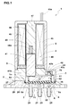
- FIG. 1 is a cross-sectional view of a valve device 1 in the present embodiment.
- the valve device 1 in the present embodiment has a valve main body 2 having a port through which fluid flows, and defining a valve chest, a valve 3 for opening and closing the port, and a driving means 4 for driving the valve 3 to open and close the port.
- the valve main body 2 has a flow path block 20 and a sub-block 5.
- the flow path block 20 is, for example, formed of a resin material, and has a concave portion 22 constituting a valve chest 21 which is a space through which fluid flows, an inlet port 23 (Common port) communicating with the valve chest 21, a NC (Normally Close) outlet port 24 (first outlet port), a NO (Normally Open) outlet port 25 (second outlet port), and a holding surface 26 for holding the valve 3.
- the inlet port 23 is always opened. From the inlet port 23, the fluid is supplied into the valve chest 21.
- the NC outlet port 24 is closed, and the NO outlet port 25 is opened; the fluid flowing from the inlet port 23 into the valve chest 21 flows along the arrowed line (A) and flows out from the NO outlet port 25.
- the valve 3 has a diaphragm 6 disposed to cover the valve chest 21, and a swing member 7 provided swingably with respect to the valve main body 2.
- the diaphragm 6 is, for example, formed by a rubber material. By being attached to the valve main body 2 so as to cover a concave portion 22, the diaphragm 6 forms a valve chest 21 between the concave portion 22 and the diaphragm 6.
- the diaphragm 6 has a peripheral portion 6a extending outwardly.
- the swing member 7 is integrated with the diaphragm 6.
- the swing member 7 has a shaft member 71 which supports the swing member 7 rotatably.
- the swing member 7 is, for example, formed of a resin material and disposed above the inlet port 23.
- the shaft member 71 is, for example, formed of a metallic material.
- the shaft member 71 is disposed above the inlet port 23, substantially perpendicularly to the inlet port 23. And both ends thereof are supported by the sub-blocks 5.
- the driving means 4 has a valve driving unit 40 for driving the swing member 7, and a frame 8 supporting the valve driving unit 40.
- the drive means 4 presses the swing member 7 to cause the diaphragm 6 being seated on or being separated from the valve seat of the NC outlet port 24 or NO outlet port 25 to close or open the port.
- the valve device 1 of the present embodiment is a so-called solenoid valve in which, by the electromagnetic force generated by the driving means 4, the diaphragm 6 is driven to open and close the port.
- the sub-block 5 is, for example, formed of a resin material, and the sub-block has an accommodating portion 51 accommodating the swing member 7 and the like, and a pressing portion 52 pressing the diaphragm 6 to the holding surface 26.
- the sub-block 5 is mounted to the mating surface 27 in which the concave portion 22 of the flow path block 20 is formed, and the sub-block is fixed to the flow path block 20 by screws (not shown) or the like.
- the outer peripheral portion 6a of the diaphragm 6 is held and bound between the holding surface 26 of the flow path block 20 and the pressing portion 52 of the sub-block 5 by being sandwiched therebetween, and closely contacts with the flow path block 20. Thereby, the valve chest 21 is sealed, the fluid is prevented from leaking toward the outside of the flow path block 20.
- the frame 8 houses the valve driving unit 40.
- the valve driving unit 40 has a first plunger (movable iron core) 41, a second plunger 42, a first coil spring 43, a second coil spring 44, a solenoid coil 45, and a fixed iron core 46.
- the first plunger 41 is disposed above the NC outlet port 24.
- the first plunger 41 is inserted in a coil bobbin 47 around which the solenoid coil 45 is wound.
- the fixed iron core 46 is provided with a concave portion 46a in which the first coil spring 43 is loaded. One end of the first coil spring 43 contacts with the bottom of the concave portion 46a of the fixed iron core 46, and the other end contacts with the top surface of the first plunger 41.
- the first coil spring 43 pushes down the first plunger 41 toward a first contact portion 7a of the swing member 7. with this, the tip end 41b of the first plunger 41 presses the first contact portion 7a of the swing member 7.
- the spring load of the first coil spring 43 is set to be larger than the spring load of the second coil spring 44.
- the second plunger 42 is disposed above the NO outlet port 25.
- the second plunger 42 is provided with a cylindrical portion 42a in which the second coil spring 44 is inserted, and a flange-shaped tip end portion 42b formed at the end edge of the cylindrical portion 42a.
- One end of the second coil spring 44 contacts with the tip end portion 42b of the second plunger 42, and the other end contacts with the bottom of the recess of the sub-blocks 5.
- the second coil spring 44 pushes down the second plunger 42 toward a second contact portion 7b of the swing member 7. with this, the tip end portion 42b of the second plunger 42 presses the contact portion 7b of the swing member 7.
- the solenoid coil 45 is wound around the cylindrical coil bobbin 47.
- the solenoid coil 45 generates an electromagnetic force by energization.
- the solenoid coil 45 is applied by a predetermined current so as to generate an electromagnetic force larger than the difference between the load of the first coil spring 43 and the load of the second coil spring 44.
- a cable 45a for power feeding to the solenoid coil 45 and the like is led into the frame 8.
- the first plunger 41, the first coil spring 43, the solenoid coil 45, the fixed iron core 46 and the coil bobbin 47 are housed.
- the solenoid coil 45, the fixed iron core 46 and the coil bobbin 47 are fixed to the frame 8.
- the spring load of the first coil spring 43 is greater than the spring load of the second coil spring 44, therefore, the elastic force generated by the first coil spring 43 is greater than the elastic force generated by the second coil spring 44.
- the posture of the diaphragm 6 is, as shown in Figure 1 , maintained at that rotated counterclockwise in the figure, wherein the NC outlet port 24 is closed, and the NO outlet port 25 is opened. With this, as indicated by an arrow A, the fluid flowing into the valve chest 21 from the inlet port 23 is discharged from the NO outlet port 25.
- FIG. 2 shows the valve device 1 in a state where the solenoid coil 45 is energized.
- the first plunger 41 is moved in a direction to compress the first coil spring 43.
- the tip end portion 42b of the second plunger 42 presses the second contact portion 7b of the swing member 7, the diaphragm 6 is rotated clockwise, the NO outlet port 25 is closed, and the NC outlet port 24 is opened.
- the fluid flowing into the valve chest 21 from the inlet port 23 is discharged from the NC outlet port 24.
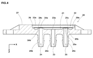
- FIG. 3 and Figure 4 show the flow path block 20.
- the flow path block 20 is provided with a concave portion 22 partitioning the valve chest 21.
- the concave portion 22 is formed so as to dent from the mating surface 27 to which the sub-block 5 is jointed.
- a NC outlet nipple 29b, an inflow nipple 29a and a NO outflow nipple 29c are formed to protrude from the rear surface opposite to the mating surface 27.
- the inlet port 23 is formed to penetrate through the inflow nipple 29a from the concave portion 22.
- the NC outlet port 24 is formed to penetrate through the NC outflow nipple 29b from the concave portion 22, and the NO outlet port 25 is formed to penetrate through the NO outflow nipple 29c from the concave portion 22.
- the NC outlet port 24, the inlet port 23 and the NO outlet port 25 are arranged in this order.
- the inlet port 23 has an inlet opening 23a which opens to face the concave portion 22.
- the inlet opening 23a is formed to communicate with the valve chest 21.
- the inlet port 23 lets the fluid flow from the inlet opening 23a into the valve chest 21.
- the NC outlet port 24 and the NO outlet port 25 have outflow openings 24a, 25a which open to face the concave portion 22.
- the outflow openings 24a, 25a are formed to communicate with the valve chest 21.
- the NC outlet port 24 and the NO outlet port 25 let the fluid flow out of the valve chest 21 through the outflow openings 24a, 25a.
- the outflow opening 24a of the NC outlet port 24 is provided with a first valve seat 24b, and the outflow opening 25a of the NO outlet port 25 is provided with a second valve seat 25b.
- the first valve seat 24b and the second valve seat 25b are formed in tubular shapes protruding toward the diaphragm 6. with the swing action of the swing member 7, the diaphragm 6 closely contacts with the tip end of the first valve seat 24b or the second valve seat 25b, and the NC outlet port 24 or the NO outlet port 25 is closed. At this time, the other outlet port is opened, and the fluid flowing into the valve chest 21 from the inlet port 23 is discharged from the opened outlet port toward the outside of the valve device 1.
- first valve seat 24b and the second valve seat 25b are formed so as to protrude toward the diaphragm 6, it is possible to improve the sealing between the diaphragm 6 and the first valve seat 24b and second valve seat 25b when the port is closured. Thereby, it is possible to prevent the fluid from leaking from the valve chest 21 to the NC outlet port 24 or NO outlet port 25 when the NC outlet port 24 or NO outlet port 25 is closed.
- the seating face of the first valve seat 24b at the tip is provided with a first raised portion 24c which is raised toward the diaphragm 6.
- the first raised portion 24c is formed continuously in the circumferential direction on the opening side of the NC outlet port 24, namely, in the inner peripheral portion of the first valve seat 24b.
- the sealing between the first valve seat 24b and the diaphragm 6 when the NC outlet port 24 is closed is more enhanced, and the leakage of the fluid is prevented.
- the second valve seat 25b of the NO outlet port 25 is provided with a first raised portion 25c.
- the holding surface 26 is formed in the peripheral edge of the concave portion 22.
- the mating surface 27 and the holding surface 26 are formed at different levels through the intervention of the side wall 22a of the concave portion 22.
- the second raised portion 26a is formed continuously in the circumferential direction.
- a pair of through holes 28 are formed substantially on the opposing corners of a main body portion 20a of the flow path block 20.
- the flow path block 20 and the sub-block 5 are fixed by screws penetrating the through holes 28.
- FIG 5 there is shown the valve 3 in which the diaphragm 6 is attached to the swing member 7.
- the center portion of the swing member 7 is provided with a through hole 7c into which a shaft member 71 (see Figure 1 ) is inserted.
- the through hole 7c is formed to penetrate the swing member 7 in the horizontal direction.
- the through hole 7c is disposed between the first contact portion 7a and the second contact portion 7b, and the distance from the through hole 7c to the first contact portion 7a is equal to the distance from the through hole 7c to the second contact portion 7b.
- the diaphragm 6 is mounted at the bottom of the swing member 7, the diaphragm 6 is mounted.
- a membrane portion 6b On the inside of the outer peripheral portion 6a of the diaphragm 6, a membrane portion 6b whose thickness is smallest in the diaphragm 6 is provided.
- the membrane portion 6b is formed along the entire circumference of the diaphragm 6.
- On the inside of the membrane portion 6b there is formed a bottom surface 6c seating on the first valve seat 24b or the second valve seat 25b when the port is closed.
- the hardness of the elastic material forming the diaphragm 6 is defined. That is, the durometer A hardness in JIS-K6253 of the elastic material forming the diaphragm 6 is preferably A50 or more, more preferably A60 or more, still more preferably A65 or more, and preferably A85 or less, more preferably the A80 or less, still more preferably A75 or less.
- the durometer A hardness of the elastic material forming the diaphragm 6 is less than A50, during the port is closed where the bottom surface 6c of the diaphragm 6 is seated on the first valve seat 24b or the second valve seat 25b, the deformation of the bottom surface 6c of the diaphragm 6 becomes excessively large, the fatigue of the elastic material forming the diaphragm 6 is accelerated, and the lifetime of the diaphragm 6 may become shorter.
- the bottom surface 6c of the diaphragm 6 becomes hard to deform along the outer shape of the first valve seat 24b or the second valve seat 25b, and adequate sealing capability may not be obtained.
- the diaphragm 6 is made of an elastic material containing, as its rubber component, at least one kind of ethylene-propylene-diene (EPDM), fluorinated rubber (FKM, FPM, FFKM), hydrogenated nitrile rubber (HNBR), butylene rubber (IIR) and silicone rubber (VMQ).
- EPDM ethylene-propylene-diene
- FKM fluorinated rubber
- FPM fluorinated rubber
- HNBR hydrogenated nitrile rubber
- IIR butylene rubber
- silicone rubber silicone rubber
- the diaphragm 6 is a part used dynamically such that contacts with the first valve seat 24b, the second valve seat 25b and the like and elastic deformation are repeated, and the diaphragm wears gradually during long-term use. Therefore, in order to improve the wear resistance of the diaphragm 6, it is preferred that the hardness is adjusted within the above-mentioned range by adding a filler to the elastic material.
- a filler it is desirable to contain at least one kind of carbon black and inorganic fillers such as calcium carbonate, silica, barium sulfate and talc.
- the amount of the filler is preferably not less than 10 parts by weight, more preferably not less than 20 parts by weight, and preferably not more than 70 parts by weight, more preferably not more than 80 parts by weight. If the amount of the filler is less than 10 parts by weight inclined with respect to 100 parts by weight of the rubber component, then the resistance to wear becomes insufficient, and the lifetime of the diaphragm 6 is shortened. If the amount of the filler exceeds 80 parts by weight with respect to 100 parts by weight of the rubber component, then the bending fatigue resistance of the diaphragm 6 is reduced, and the lifetime of the diaphragm 6 is shortened.
- the thickness of the membrane portion 6b of the diaphragm 6 is 0.2 to 1.0 mm. If the thickness of the membrane portion 6b of the diaphragm 6 is less than 0.2 mm, there is a possibility that the membrane portions 6b is broken during long term use, and although the NC outlet port 24 or NO outlet port 25 is in the closed state, the fluid leaks to the port. If the thickness of the membrane portion 6b of the diaphragm 6 is more than 1.0 mm, the force required to swing the swing member 7 becomes increased, and there is a possibility that the solenoid coil 45 or the like becomes large-sized.
- the pressure on the first valve seat 24b or the second valve seat 25b, which is of the diaphragm 6 seating on the first valve seat 24b or the second valve seat 25b is defined. That is, it is preferred that the pressure on the first valve seat 24b or the like of the diaphragm 6 is 0.5 to 1.0 N/sq.mm.
- the pressure on the first valve seat 24b and the like, of the diaphragm 6 is less than 0.5 N/sq.mm, then the bottom surface 6c of the diaphragm 6 becomes hard to deform along the outer shape of the first valve seat 24b and the like, and there is a possibility that sufficient sealing capability can not be obtained.
- the pressure on the first valve seat 24b and the like, of the diaphragm 6 is more than 1.0 N/sq.mm, then the deformation of the bottom 6c of the diaphragm 6 when seating becomes excessively large, and there is a possibility that the fatigue of the elastic material constituting the diaphragm 6 is accelerated, and the lifetime of the diaphragm 6 becomes shorter.
- the pressure on the first valve seat 24b, of the diaphragm 6 is calculated as the force of the diaphragm 6 to press the first valve seat 24b divided by the contact area S1 of the diaphragm 6 and the first valve seat 24b.
- the pressure on the second valve seat 25b, of the diaphragm 6 is calculated as the force of the diaphragm 6 to press the second valve seat 25b divided by the contact area S2 of the diaphragm 6 and the second valve seat 25b.
- the difference between the pressure of the diaphragm 6 seating on the first valve seat 24b of the NC outlet port 24 and the pressure of the diaphragm 6 seating on the first valve seat 25b of the NO outlet port 25 is preferably 0.02 N/sq.mm or more, more preferably 0.04 N/sq.mm or more, and preferably 0.40 N/sq.mm or less, more preferably 0.2 N/sq.mm or less. If the above-mentioned difference between the pressure on the first valve seat 24b and the pressure on the second valve seat 25b, of the diaphragm 6 is less than 0.02 N/sq.mm, there is a possibility that sufficient sealing capability can not be obtained.
- the difference between the pressure on the first valve seat 24b and the pressure on the second valve seat 25b, of the diaphragm 6 is more than 0.40 N/sq.mm, there is a possibility that the wear of the diaphragm 6 concentrates on the side where the pressure is larger, and the lifetime of the diaphragm 6 becomes shorter.
- the load which the valve driving unit 40 applies to the diaphragm 6 via the swing member 7 is set within the following range.
- FIG. 6 there is shown a main part of the valve device 1 under such a condition that the NC outlet port 24 is closed by the diaphragm 6.
- the load L1 of the swing member 7 to press a first valve seat 24b side of the diaphragm 6 is preferably not less than 2.9 N, more preferably not less than 3.2 N, and preferably, not more than 4.0 N, more preferably not more than 3.8 N.
- the load L1 of the swing member 7 to press the first valve seat 24b side of the diaphragm 6 is calculated by the difference between the load L ⁇ 1 by the first coil spring 43 when the length is ⁇ 1 and the load L ⁇ 1 by the second coil spring 44 when the length is ⁇ 1.
- the load by the first coil spring 43 alone is 5.8 N to 8.0 N, and it is desirable that the load by the second coil spring 44 alone is 2.9 N to 4.0 N. If the load by the first coil spring 43 alone is less than 5.8 N, and if the load by the second coil spring 44 alone is less than 2.9 N, then the bottom surface 6c of the diaphragm 6 becomes hard to deform along the outer shape of the second valve seat 25b and the like, and there is a possibility that sufficient sealing capability can be obtained.
- FIG. 7 there is shown the main part of the valve device 1 under such a condition that the NO outlet port 25 is closed by the diaphragm 6.
- the load L2 of the swing member 7 to press a second valve seat 25b side of the diaphragm 6 is preferably not less than 2.4 N, more preferably not less than 2.7 N, and preferably m ⁇ not more than 3.5 N, more preferably not more than 3.3 N.
- the first plunger 41 is spaced apart from the swing member 7, a force is not transmitted to the swing member 7 by the first plunger 41.
- the load L2 of the swing member 7 to press the second valve seat 25b side of the diaphragm 6 becomes equal to the load L ⁇ 2 by the second coil spring 44 when the length is ⁇ 2, the gravity and the like. If the load L2 of the swing member 7 to press the second valve seat 25b side of the diaphragm 6 is less than 2.4 N, then the bottom surface 6c of the diaphragm 6 becomes hard to deform along the outer shape of second valve seat 25b and the like, and there is a possibility that sufficient sealing capability can not be obtained.
- the load by the second coil spring 44 alone is 2.4 N to 3.5 N. If the load by the second coil spring 44 alone is less than 2.4N, then the bottom surface 6c of the diaphragm 6 becomes hard to deform along the outer shape of the second valve seat 25b and the like, and there is a possibility that sufficient sealing capability can not be obtained. On the other hand, if the load by the second coil spring 44 alone is more than 3.5N, then the load by the first coil spring 43 alone is need to be increased more than that. As a result, it becomes difficult to downsize the driving means 4 and thus the valve device 1 similarly to the above.
- the diaphragm 6 is made of an elastic material whose durometer A hardness in JIS-K6253 is A50 to A85, and the pressure on the first valve seat 24b or the second valve seat 25b, of the diaphragm 6 when sitting is 0.5 to 1.0 N/sq.mm.
- the hardness and seating pressure of the diaphragm 6 are improved, excessive deformation of the diaphragm 6 when sitting can be suppressed, and thereby the durability of the diaphragm 6 can be improved.
- the diaphragm 6 is moderately deformed with respect to the first valve seat 24b or the second valve seat 25b, and sufficient sealing capability can be obtained.
- the valve driving unit 40 such as the solenoid coil 45 can be miniaturized.
- FIG. 3 to 4 and so on there is shown the flow path block 20 of a three-way valve having two systems of the outlet ports 24, 25 for the single inlet port 23.
- Such flow path block 20 can be used as a two-way valve by always closing either one of the outlet ports 24 and 25, for example, the outlet port 24. Even in such a usage pattern, the same effects as described above can be obtained since the hardness and seating pressure of the diaphragm 6 are improved. Even when the other outlet port 25 is always closed, it is the same as described above.
- valve device according to the present invention
- present invention can be embodied in various forms without being limited to the above described specific embodiment.
- the valve device having the basic structure shown in Figure 1 was experimentally manufactured based on the specifications shown in Table 1, and the sealing performance and durability of the diaphragm were evaluated.
- the diaphragms of each specification was experimentally manufactured by cross-linking molding using a press machine.
- a type-A durometer hardness according to JIS K 6253-3 was measured. The test methods are as follows.
- the diaphragm of each specification was incorporated into a valve device, and the sealing performance was measured. More specifically, inputting an air inflow of 0.3 MPa through the inlet port, the pressure of the air after 3 minutes was measured. The result is an index based on working Example 1 being 100, wherein the larger value indicates that the sealing performance of the diaphragm is better.
- the valve device in which the diaphragm of each specification was incorporated was subjected to idle operations ten million times at a frequency of 5 Hz at a room temperature of 20 degrees C. Then, inputting an air flow of 0.3 MPa through the inlet port, the pressure of the air after three minute was measured.
- the result is an index based on working Example 1 being 100, wherein the larger value indicates that the fatigue of the diaphragm is less, and the durability is better.
- valve devices as working Examples were significantly excellent at the sealing performance and durability as compared with Comparative Examples.
Landscapes
- Engineering & Computer Science (AREA)
- General Engineering & Computer Science (AREA)
- Mechanical Engineering (AREA)
- Health & Medical Sciences (AREA)
- Clinical Laboratory Science (AREA)
- Chemical & Material Sciences (AREA)
- Chemical Kinetics & Catalysis (AREA)
- Magnetically Actuated Valves (AREA)
- Details Of Valves (AREA)
- Multiple-Way Valves (AREA)
- Fluid-Driven Valves (AREA)
Abstract
Description
- The present invention relates to a valve device to be used in various analyzing devices such as chemical testing devices, environmental analyzing devices and biotechnology research devices.
- In such various analyzing devices, important problems are an improvement of the measurement accuracy, an improvement of the inspecting speed, minimization of a specimen and a reagent, and downsizing of the device. And a valve device for controlling a flow rate of a fluid used in the measurement is required to be further improved in its performance. In such valve device, a diaphragm made of a rubber material or the like having elasticity is employed as a valve opening/closing mechanism in order to realize excellent chemical resistance. The diaphragm forms a bulkhead that divides a valve chest, and receives an external driving force to switch fluid passages.
- In this kind of valve device, in order to precisely control the flow rate of the fluid, it is necessary to improve the sealing capability of the diaphragm at the time of closing of a port. The sealing capability of the diaphragm at the time of closing the port can be improved by increasing the load for pressing the diaphragm when seating the diaphragm on a valve seat formed around the opening of the port, i.e., the pressure of the diaphragm on the valve seat when seated.
- However, when a large load is applied to the diaphragm, the fatigue of the rubber material constituting the diaphragm is accelerated, and the life of the diaphragm may be shortened. Further, it is concerned that in order to press the diaphragm with a large load, a proportionate driving means is required, and the valve device increase in size.
- Under these circumstances, the following
Patent Document 1 discloses a valve mechanism of a valve device whose diaphragm is driven by a solenoid, a first spring member, a second spring member and the like, in which the resilient force (spring force) of the second spring member is set to be twice the resilient force of the first spring member. - Patent Document 1: Japanese Unexamined Patent Publication No.
2000-297876 - However, even in the above-described valve device, it is difficult to achieve both of the diaphragm's sealing capability and durability, while reducing the size of the device.
- In view of the circumstances as described above, the present invention was made, and a main object is to provide a valve device in which both of the diaphragm's sealing capability and durability can be achieved, while reducing the size.
- The present invention is a valve device having a valve main body defining a valve chest having at least one port through which fluid flows,
a valve for opening and closing the port, and
a drive means for driving the valve to open and close the port, the port having an opening around which a valve seat is formed, the valve disposed so as to cover the valve chest and having a diaphragm for seating on or separating from the valve seat to open and close the port,
characterized in that
the diaphragm is made of an elastic material whose durometer A hardness in JIS-K6253 is A50 to A85, and
the pressure of the diaphragm on the valve seat when seated is 0.5 to 1.0 N/sq.mm. - In the valve device according to the present invention, it is desirable that the durometer A hardness in JIS-K6253 of the diaphragm is A60 to A80.
- In the valve device according to the present invention, it is desirable that the diaphragm includes, as a rubber component, at least one kind of ethylene-propylene-diene, fluorinated rubber, hydrogenated nitrile rubber, butylene rubber and silicone rubber.
- In the valve device according to the present invention, it is desirable that the diaphragm includes, as fillers, at least one kind of calcium carbonate, silica, barium sulfate, talc and carbon black.
- In the valve device according to the present invention, it is desirable that the port has an inlet port for flowing a fluid into the valve chest, and an outlet port for flowing out the fluid from the valve chest, and
the diaphragm opens and closes at least one of the inlet port and the outlet port. - In the valve device according to the present invention, it is desirable that
the port has an inlet port for flowing a fluid into the valve chest, and an outlet port for flowing out the fluid from the valve chest,
the outlet port provides two systems of a first outlet port and a second outlet port, and
the diaphragm opens and closes the first outlet port and the second outlet port. - In the valve device according to the present invention, it is desirable that
the diaphragm is intended to open and close the first outlet port and the second outlet port alternately, and
the difference between the pressure of the diaphragm seated on the valve seat of the first outlet port and the pressure of the diaphragm seated on the valve seat of the second outlet port is not more than 0.40 N/sq.mm. - In the valve device according to the present invention, it is desirable that the valve is driven by the driving means to swing and to open and close the port.
- In the valve device according to the present invention, it is desirable that the valve is rotatably supported by a shaft member.
- The diaphragm of the valve device of the present invention is made of the elastic material whose durometer A hardness in JIS-K6253 is A50 to A85, and the pressure on the valve seat, of the diaphragm seated thereon is 0.5 to 1.0 N/sq.mm.
As the hardness of the diaphragm and the seating pressure are improved in this manner, the diaphragm is prevented from being excessively deformed at the time of sitting, and it is possible to improve the durability of the diaphragm. At the same time, the diaphragm is moderately deformed for the valve seat, and it is possible to obtain sufficient sealing capability.
Further, the driving means can be miniaturized since there is no need to press the diaphragm at an excessively large load. -
- [
Figure 1 ] A cross-sectional view showing a valve device according to an embodiment of the present invention. - [
Figure 2 ] A cross-sectional view showing the valve device in a state in which a solenoid coil inFigure 1 is energized. - [
Figure 3 ] A perspective view of a flow path block inFigure 1 . - [
Figure 4 ] A cross-sectional view of the flow path block inFigure 1 . - [
Figure 5 ] (a) is a side view of an oscillating member to which the diaphragm is attached, (b) is an A-A line cross-sectional view of (a). - [
Figure 6 ] A cross-sectional view showing a main part of the valve device in a state in which a NC outlet port is closed. - [
Figure 7 ] A cross-sectional view showing the main part of the valve device in a state in which a NO outlet port is closed. - Hereinafter, an embodiment of the present invention will be described with reference to the accompanying drawings.
Figure 1 is a cross-sectional view of avalve device 1 in the present embodiment. As shown inFigure 1 , thevalve device 1 in the present embodiment has
a valvemain body 2 having a port through which fluid flows, and defining a valve chest,
avalve 3 for opening and closing the port, and
a driving means 4 for driving thevalve 3 to open and close the port. - The valve
main body 2 has aflow path block 20 and asub-block 5. Theflow path block 20 is, for example, formed of a resin material, and has
aconcave portion 22 constituting avalve chest 21 which is a space through which fluid flows,
an inlet port 23 (Common port) communicating with thevalve chest 21,
a NC (Normally Close) outlet port 24 (first outlet port),
a NO (Normally Open) outlet port 25 (second outlet port), and
aholding surface 26 for holding thevalve 3.
As shown inFigure 1 , theinlet port 23 is always opened. From theinlet port 23, the fluid is supplied into thevalve chest 21. In the normal state, theNC outlet port 24 is closed, and theNO outlet port 25 is opened; the fluid flowing from theinlet port 23 into thevalve chest 21 flows along the arrowed line (A) and flows out from theNO outlet port 25. - The
valve 3 has adiaphragm 6 disposed to cover thevalve chest 21, and aswing member 7 provided swingably with respect to the valvemain body 2. - The
diaphragm 6 is, for example, formed by a rubber material. By being attached to the valvemain body 2 so as to cover aconcave portion 22, thediaphragm 6 forms avalve chest 21 between theconcave portion 22 and thediaphragm 6. Thediaphragm 6 has aperipheral portion 6a extending outwardly. - The
swing member 7 is integrated with thediaphragm 6. Theswing member 7 has ashaft member 71 which supports theswing member 7 rotatably. Theswing member 7 is, for example, formed of a resin material and disposed above theinlet port 23. Theshaft member 71 is, for example, formed of a metallic material. Theshaft member 71 is disposed above theinlet port 23, substantially perpendicularly to theinlet port 23. And both ends thereof are supported by thesub-blocks 5. - As the
swing member 7 rotates like a seesaw around theshaft member 71 as the rotational axis, one of theNC outlet port 24 and theNO outlet port 25 is closed, and the other is opened. Thereby, each port is alternately opened and closed. - The driving means 4 has a
valve driving unit 40 for driving theswing member 7, and aframe 8 supporting thevalve driving unit 40. The drive means 4 presses theswing member 7 to cause thediaphragm 6 being seated on or being separated from the valve seat of theNC outlet port 24 or NOoutlet port 25 to close or open the port.
Thevalve device 1 of the present embodiment is a so-called solenoid valve in which, by the electromagnetic force generated by the driving means 4, thediaphragm 6 is driven to open and close the port. - The
sub-block 5 is, for example, formed of a resin material, and the sub-block has anaccommodating portion 51 accommodating theswing member 7 and the like, and apressing portion 52 pressing thediaphragm 6 to the holdingsurface 26. Thesub-block 5 is mounted to themating surface 27 in which theconcave portion 22 of the flow path block 20 is formed, and the sub-block is fixed to the flow path block 20 by screws (not shown) or the like.
The outerperipheral portion 6a of thediaphragm 6 is held and bound between the holdingsurface 26 of the flow path block 20 and thepressing portion 52 of thesub-block 5 by being sandwiched therebetween, and closely contacts with theflow path block 20. Thereby, thevalve chest 21 is sealed, the fluid is prevented from leaking toward the outside of theflow path block 20. - At the top of the
sub-block 5, theframe 8 is provided. Theframe 8 houses thevalve driving unit 40. - The
valve driving unit 40 has a first plunger (movable iron core) 41, asecond plunger 42, afirst coil spring 43, asecond coil spring 44, asolenoid coil 45, and a fixediron core 46.
Thefirst plunger 41 is disposed above theNC outlet port 24. Thefirst plunger 41 is inserted in acoil bobbin 47 around which thesolenoid coil 45 is wound.
The fixediron core 46 is provided with aconcave portion 46a in which thefirst coil spring 43 is loaded.
One end of thefirst coil spring 43 contacts with the bottom of theconcave portion 46a of the fixediron core 46, and the other end contacts with the top surface of thefirst plunger 41.
Thefirst coil spring 43 pushes down thefirst plunger 41 toward afirst contact portion 7a of theswing member 7. with this, thetip end 41b of thefirst plunger 41 presses thefirst contact portion 7a of theswing member 7.
The spring load of thefirst coil spring 43 is set to be larger than the spring load of thesecond coil spring 44. - The
second plunger 42 is disposed above theNO outlet port 25. Thesecond plunger 42 is provided with acylindrical portion 42a in which thesecond coil spring 44 is inserted, and
a flange-shapedtip end portion 42b formed at the end edge of thecylindrical portion 42a.
One end of thesecond coil spring 44 contacts with thetip end portion 42b of thesecond plunger 42, and the other end contacts with the bottom of the recess of thesub-blocks 5.
Thesecond coil spring 44 pushes down thesecond plunger 42 toward asecond contact portion 7b of theswing member 7. with this, thetip end portion 42b of thesecond plunger 42 presses thecontact portion 7b of theswing member 7. - The
solenoid coil 45 is wound around thecylindrical coil bobbin 47. Thesolenoid coil 45 generates an electromagnetic force by energization.
Thesolenoid coil 45 is applied by a predetermined current so as to generate an electromagnetic force larger than the difference between the load of thefirst coil spring 43 and the load of thesecond coil spring 44.
Acable 45a for power feeding to thesolenoid coil 45 and the like is led into theframe 8.
In theframe 8, thefirst plunger 41, thefirst coil spring 43, thesolenoid coil 45, the fixediron core 46 and thecoil bobbin 47 are housed.
Thesolenoid coil 45, the fixediron core 46 and thecoil bobbin 47 are fixed to theframe 8. - Hereinafter, the switching action of the
valve device 1 is described. - As already mentioned, the spring load of the
first coil spring 43 is greater than the spring load of thesecond coil spring 44, therefore, the elastic force generated by thefirst coil spring 43 is greater than the elastic force generated by thesecond coil spring 44. In the normal state, therefore, the posture of thediaphragm 6 is, as shown inFigure 1 , maintained at that rotated counterclockwise in the figure, wherein theNC outlet port 24 is closed, and theNO outlet port 25 is opened. With this, as indicated by an arrow A, the fluid flowing into thevalve chest 21 from theinlet port 23 is discharged from theNO outlet port 25. -
Figure 2 shows thevalve device 1 in a state where thesolenoid coil 45 is energized. When a predetermined current flows through thesolenoid coil 45, then by the electromagnetic force, thefirst plunger 41 is moved in a direction to compress thefirst coil spring 43. At this time, since thetip end portion 42b of thesecond plunger 42 presses thesecond contact portion 7b of theswing member 7, thediaphragm 6 is rotated clockwise, theNO outlet port 25 is closed, and theNC outlet port 24 is opened. With this, as indicated by an arrow B, the fluid flowing into thevalve chest 21 from theinlet port 23 is discharged from theNC outlet port 24. -
Figure 3 andFigure 4 show theflow path block 20. The flow path block 20 is provided with aconcave portion 22 partitioning thevalve chest 21.
Theconcave portion 22 is formed so as to dent from themating surface 27 to which thesub-block 5 is jointed.
As shown inFigure 4 , aNC outlet nipple 29b, aninflow nipple 29a and aNO outflow nipple 29c are formed to protrude from the rear surface opposite to themating surface 27.
Theinlet port 23 is formed to penetrate through theinflow nipple 29a from theconcave portion 22.
TheNC outlet port 24 is formed to penetrate through theNC outflow nipple 29b from theconcave portion 22, and theNO outlet port 25 is formed to penetrate through theNO outflow nipple 29c from theconcave portion 22.
TheNC outlet port 24, theinlet port 23 and theNO outlet port 25 are arranged in this order. - The
inlet port 23 has aninlet opening 23a which opens to face theconcave portion 22. Theinlet opening 23a is formed to communicate with thevalve chest 21. Theinlet port 23 lets the fluid flow from the inlet opening 23a into thevalve chest 21.
TheNC outlet port 24 and theNO outlet port 25 haveoutflow openings concave portion 22. Theoutflow openings valve chest 21. TheNC outlet port 24 and theNO outlet port 25 let the fluid flow out of thevalve chest 21 through theoutflow openings - The
outflow opening 24a of theNC outlet port 24 is provided with afirst valve seat 24b, and
theoutflow opening 25a of theNO outlet port 25 is provided with asecond valve seat 25b.
Thefirst valve seat 24b and thesecond valve seat 25b are formed in tubular shapes protruding toward thediaphragm 6. with the swing action of theswing member 7, thediaphragm 6 closely contacts with the tip end of thefirst valve seat 24b or thesecond valve seat 25b, and theNC outlet port 24 or theNO outlet port 25 is closed. At this time, the other outlet port is opened, and the fluid flowing into thevalve chest 21 from theinlet port 23 is discharged from the opened outlet port toward the outside of thevalve device 1.
Since thefirst valve seat 24b and thesecond valve seat 25b are formed so as to protrude toward thediaphragm 6, it is possible to improve the sealing between thediaphragm 6 and thefirst valve seat 24b andsecond valve seat 25b when the port is closured. Thereby, it is possible to prevent the fluid from leaking from thevalve chest 21 to theNC outlet port 24 or NOoutlet port 25 when theNC outlet port 24 or NOoutlet port 25 is closed. - The seating face of the
first valve seat 24b at the tip is provided with a first raisedportion 24c which is raised toward thediaphragm 6. The first raisedportion 24c is formed continuously in the circumferential direction on the opening side of theNC outlet port 24, namely, in the inner peripheral portion of thefirst valve seat 24b. By the first raisedportion 24c, the sealing between thefirst valve seat 24b and thediaphragm 6 when theNC outlet port 24 is closed is more enhanced, and the leakage of the fluid is prevented.
Similarly, thesecond valve seat 25b of theNO outlet port 25 is provided with a first raisedportion 25c. - The holding
surface 26 is formed in the peripheral edge of theconcave portion 22. Themating surface 27 and the holdingsurface 26 are formed at different levels through the intervention of theside wall 22a of theconcave portion 22.
In the inner peripheral part of the holdingsurface 26, there is formed a second raisedportion 26a which is raised toward thediaphragm 6. The second raisedportion 26a is formed continuously in the circumferential direction. By the second raisedportion 26a, the sealing between the outerperipheral portion 6a of the holdingsurface 26 and thediaphragm 6 is enhanced, and the leakage of the fluid is prevented. - On the periphery of the
concave portion 22, a pair of throughholes 28 are formed substantially on the opposing corners of amain body portion 20a of theflow path block 20. The flow path block 20 and thesub-block 5 are fixed by screws penetrating the through holes 28. - In
Figure 5 , there is shown thevalve 3 in which thediaphragm 6 is attached to theswing member 7. The center portion of theswing member 7 is provided with a throughhole 7c into which a shaft member 71 (seeFigure 1 ) is inserted. The throughhole 7c is formed to penetrate theswing member 7 in the horizontal direction. The throughhole 7c is disposed between thefirst contact portion 7a and thesecond contact portion 7b, and the distance from the throughhole 7c to thefirst contact portion 7a is equal to the distance from the throughhole 7c to thesecond contact portion 7b. At the bottom of theswing member 7, thediaphragm 6 is mounted. On the inside of the outerperipheral portion 6a of thediaphragm 6, amembrane portion 6b whose thickness is smallest in thediaphragm 6 is provided. Themembrane portion 6b is formed along the entire circumference of thediaphragm 6. On the inside of themembrane portion 6b, there is formed abottom surface 6c seating on thefirst valve seat 24b or thesecond valve seat 25b when the port is closed. As a result of an elastic deformation of themembrane portion 6b of thediaphragm 6 following to the swing motion of theswing member 7, thevalve chest 21 is maintained between the flow path block 20 and thediaphragm 6. - In the present invention, in order to achieve both of the sealing capability and durability of the
diaphragm 6, the hardness of the elastic material forming thediaphragm 6 is defined. That is, the durometer A hardness in JIS-K6253 of the elastic material forming thediaphragm 6 is preferably A50 or more, more preferably A60 or more, still more preferably A65 or more, and preferably A85 or less, more preferably the A80 or less, still more preferably A75 or less.
If the durometer A hardness of the elastic material forming thediaphragm 6 is less than A50, during the port is closed where thebottom surface 6c of thediaphragm 6 is seated on thefirst valve seat 24b or thesecond valve seat 25b, the deformation of thebottom surface 6c of thediaphragm 6 becomes excessively large, the fatigue of the elastic material forming thediaphragm 6 is accelerated, and the lifetime of thediaphragm 6 may become shorter. On the other hand, if the durometer A hardness of the elastic material forming thediaphragm 6 is more than A85, thebottom surface 6c of thediaphragm 6 becomes hard to deform along the outer shape of thefirst valve seat 24b or thesecond valve seat 25b, and adequate sealing capability may not be obtained. - In the present embodiment, for example, the
diaphragm 6 is made of an elastic material containing, as its rubber component, at least one kind of ethylene-propylene-diene (EPDM), fluorinated rubber (FKM, FPM, FFKM), hydrogenated nitrile rubber (HNBR), butylene rubber (IIR) and silicone rubber (VMQ).
If a rubber material whose polymer main chain includes a double bond is used, there is a possibility that the polymer main chain is broken during long-term use, and thediaphragm 6 can not maintain its durability. From the view points of gas barrier properties, heat resistance, chemical resistance and production cost, the ethylene-propylene-diene is particularly preferable among the above-mentioned rubber components. - The
diaphragm 6 is a part used dynamically such that contacts with thefirst valve seat 24b, thesecond valve seat 25b and the like and elastic deformation are repeated, and the diaphragm wears gradually during long-term use. Therefore, in order to improve the wear resistance of thediaphragm 6, it is preferred that the hardness is adjusted within the above-mentioned range by adding a filler to the elastic material.
As to the filler, it is desirable to contain at least one kind of carbon black and inorganic fillers such as calcium carbonate, silica, barium sulfate and talc. From the view point of the durability of thediaphragm 6, the amount of the filler is preferably not less than 10 parts by weight, more preferably not less than 20 parts by weight, and preferably not more than 70 parts by weight, more preferably not more than 80 parts by weight.
If the amount of the filler is less than 10 parts by weight inclined with respect to 100 parts by weight of the rubber component, then the resistance to wear becomes insufficient, and the lifetime of thediaphragm 6 is shortened. If the amount of the filler exceeds 80 parts by weight with respect to 100 parts by weight of the rubber component, then the bending fatigue resistance of thediaphragm 6 is reduced, and the lifetime of thediaphragm 6 is shortened. - It is desirable than the thickness of the
membrane portion 6b of thediaphragm 6 is 0.2 to 1.0 mm.
If the thickness of themembrane portion 6b of thediaphragm 6 is less than 0.2 mm, there is a possibility that themembrane portions 6b is broken during long term use, and although theNC outlet port 24 or NOoutlet port 25 is in the closed state, the fluid leaks to the port.
If the thickness of themembrane portion 6b of thediaphragm 6 is more than 1.0 mm, the force required to swing theswing member 7 becomes increased, and there is a possibility that thesolenoid coil 45 or the like becomes large-sized. - In the present invention, in order to achieve both of the sealing capability and the durability of the
diaphragm 6, the pressure on thefirst valve seat 24b or thesecond valve seat 25b, which is of thediaphragm 6 seating on thefirst valve seat 24b or thesecond valve seat 25b, is defined.
That is, it is preferred that the pressure on thefirst valve seat 24b or the like of thediaphragm 6 is 0.5 to 1.0 N/sq.mm. If the pressure on thefirst valve seat 24b and the like, of thediaphragm 6 is less than 0.5 N/sq.mm, then thebottom surface 6c of thediaphragm 6 becomes hard to deform along the outer shape of thefirst valve seat 24b and the like, and there is a possibility that sufficient sealing capability can not be obtained.
On the other hand, if the pressure on thefirst valve seat 24b and the like, of thediaphragm 6 is more than 1.0 N/sq.mm, then the deformation of the bottom 6c of thediaphragm 6 when seating becomes excessively large, and there is a possibility that the fatigue of the elastic material constituting thediaphragm 6 is accelerated, and the lifetime of thediaphragm 6 becomes shorter. The pressure on thefirst valve seat 24b, of thediaphragm 6 is calculated as the force of thediaphragm 6 to press thefirst valve seat 24b divided by the contact area S1 of thediaphragm 6 and thefirst valve seat 24b.
Similarly, the pressure on thesecond valve seat 25b, of thediaphragm 6 is calculated as the force of thediaphragm 6 to press thesecond valve seat 25b divided by the contact area S2 of thediaphragm 6 and thesecond valve seat 25b. - The difference between the pressure of the
diaphragm 6 seating on thefirst valve seat 24b of theNC outlet port 24 and the pressure of thediaphragm 6 seating on thefirst valve seat 25b of theNO outlet port 25 is preferably 0.02 N/sq.mm or more, more preferably 0.04 N/sq.mm or more, and preferably 0.40 N/sq.mm or less, more preferably 0.2 N/sq.mm or less.
If the above-mentioned difference between the pressure on thefirst valve seat 24b and the pressure on thesecond valve seat 25b, of thediaphragm 6 is less than 0.02 N/sq.mm, there is a possibility that sufficient sealing capability can not be obtained.
On the other hand, if the difference between the pressure on thefirst valve seat 24b and the pressure on thesecond valve seat 25b, of thediaphragm 6 is more than 0.40 N/sq.mm, there is a possibility that the wear of thediaphragm 6 concentrates on the side where the pressure is larger, and the lifetime of thediaphragm 6 becomes shorter. - In the present embodiment, in order that the pressure on the
first valve seat 24b or thesecond valve seat 25b, of thediaphragm 6 when seating is set within the above range, the load which thevalve driving unit 40 applies to thediaphragm 6 via theswing member 7 is set within the following range. - In
Figure 6 , there is shown a main part of thevalve device 1 under such a condition that theNC outlet port 24 is closed by thediaphragm 6.
In the state of thediaphragm 6 seating on thefirst valve seat 24b, i.e., when the electrical signal in order to raise thefirst plunger 41 is not supplied to thesolenoid coil 45, the load L1 of theswing member 7 to press afirst valve seat 24b side of thediaphragm 6 is preferably not less than 2.9 N, more preferably not less than 3.2 N, and preferably, not more than 4.0 N, more preferably not more than 3.8 N.
In such state, both of thefirst plunger 41 and thesecond plunger 42 contact with theswing member 7, and the forces transmitted to theswing member 7 by thefirst plunger 41 and thesecond plunger 42 are canceled. Therefore, the load L1 of theswing member 7 to press thefirst valve seat 24b side of thediaphragm 6 is calculated by the difference between the load Lα1 by thefirst coil spring 43 when the length is α1 and the load Lβ1 by thesecond coil spring 44 when the length is β1.
If the Load L1 of theswing member 7 to press thefirst valve seat 24b side of thediaphragm 6 is less than 2.9 N, thebottom surface 6c of thediaphragm 6 becomes hard to deform along the outer shape of thefirst valve seat 24b and the like, and there is a possibility that sufficient sealing capability can be obtained.
On the other hand, if the Load L1 of theswing member 7 to press thefirst valve seat 24b side of thediaphragm 6 is more than 4.0 N, the deformation of thebottom surface 6c of thediaphragm 6 seating on thefirst valve seat 24b becomes excessively large, and there is a possibility that the fatigue of the elastic material forming thediaphragm 6 is accelerated, and the lifetime of thediaphragm 6 becomes shorter. - Further, in the state where the
NC outlet port 24 is closed by thediaphragm 6, it is desirable that the load by thefirst coil spring 43 alone is 5.8 N to 8.0 N, and it is desirable that the load by thesecond coil spring 44 alone is 2.9 N to 4.0 N.
If the load by thefirst coil spring 43 alone is less than 5.8 N, and if the load by thesecond coil spring 44 alone is less than 2.9 N, then thebottom surface 6c of thediaphragm 6 becomes hard to deform along the outer shape of thesecond valve seat 25b and the like, and there is a possibility that sufficient sealing capability can be obtained.
On the other hand, if the load by thefirst coil spring 43 alone is more than 8.0 N, and if the load by thesecond coil spring 44 alone is more than 4.0 N then the size of thesolenoid coil 45 increases, and it becomes difficult to achieve the downsizing of thevalve device 1. - In
Figure 7 , there is shown the main part of thevalve device 1 under such a condition that theNO outlet port 25 is closed by thediaphragm 6.
In the state of thediaphragm 6 seating on thesecond valve seat 25b, i.e., when the electrical signal to raise thefirst plunger 41 is supplied to thesolenoid coil 45, the load L2 of theswing member 7 to press asecond valve seat 25b side of thediaphragm 6 is preferably not less than 2.4 N, more preferably not less than 2.7 N, and preferably m\not more than 3.5 N, more preferably not more than 3.3 N.
In this state, as thefirst plunger 41 is spaced apart from theswing member 7, a force is not transmitted to theswing member 7 by thefirst plunger 41. Accordingly, the load L2 of theswing member 7 to press thesecond valve seat 25b side of thediaphragm 6 becomes equal to the load Lβ2 by thesecond coil spring 44 when the length is β2, the gravity and the like.
If the load L2 of theswing member 7 to press thesecond valve seat 25b side of thediaphragm 6 is less than 2.4 N, then thebottom surface 6c of thediaphragm 6 becomes hard to deform along the outer shape ofsecond valve seat 25b and the like, and
there is a possibility that sufficient sealing capability can not be obtained.
On the other hand, if the load L2 of theswing member 7 to press thesecond valve seat 25b side of thediaphragm 6 is more than 3.5 N, then the deformation of thebottom surface 6c of thediaphragm 6 seating on thesecond valve seat 25b is excessively increased, and there is a possibility that the fatigue of the elastic material forming thediaphragm 6 is accelerated, and the lifetime of thediaphragm 6 becomes shorter. Even in this case, it is necessary that the spring load of thefirst coil spring 43 is increased more than the spring load of thesecond coil spring 44. For this reason, it is necessary to increase the electromagnetic force generated by thesolenoid coil 45. As a result, an increase in the size of thesolenoid coil 45 is necessitated, and it becomes difficult to downsize the driving means 4 and thus to downsize thevalve device 1. - Further, in the state where the
NO outlet port 25 is closed by thediaphragm 6, it is preferable that the load by thesecond coil spring 44 alone is 2.4 N to 3.5 N.
If the load by thesecond coil spring 44 alone is less than 2.4N, then thebottom surface 6c of thediaphragm 6 becomes hard to deform along the outer shape of thesecond valve seat 25b and the like, and there is a possibility that sufficient sealing capability can not be obtained.
On the other hand, if the load by thesecond coil spring 44 alone is more than 3.5N, then the load by thefirst coil spring 43 alone is need to be increased more than that. As a result,
it becomes difficult to downsize the driving means 4 and thus thevalve device 1 similarly to the above. - As described above, according to the
valve device 1 of the present invention, thediaphragm 6 is made of an elastic material whose durometer A hardness in JIS-K6253 is A50 to A85, and the pressure on thefirst valve seat 24b or thesecond valve seat 25b, of thediaphragm 6 when sitting is 0.5 to 1.0 N/sq.mm. In this way, as the hardness and seating pressure of thediaphragm 6 are improved, excessive deformation of thediaphragm 6 when sitting can be suppressed, and thereby the durability of thediaphragm 6 can be improved.
Further, thediaphragm 6 is moderately deformed with respect to thefirst valve seat 24b or thesecond valve seat 25b, and sufficient sealing capability can be obtained.
Furthermore, since there is no need to press thediaphragm 6 at excessively heavy load, thevalve driving unit 40 such as thesolenoid coil 45 can be miniaturized. - In
Figures 3 to 4 and so on, there is shown the flow path block 20 of a three-way valve having two systems of theoutlet ports single inlet port 23.
Such flow path block 20 can be used as a two-way valve by always closing either one of theoutlet ports outlet port 24. Even in such a usage pattern, the same effects as described above can be obtained since the hardness and seating pressure of thediaphragm 6 are improved. Even when theother outlet port 25 is always closed, it is the same as described above. - Further, even in such a structure that either one of the outlet ports is omitted from the
flow path block 20, it is possible to use it as a two-way valve in the same manner as described above, and the same effects as described above can be obtained. In this case, it is not necessary to arrange theinlet port 23 in the central portion of thevalve chest 21. It may be disposed on the side of the omitted outlet port. - while detailed description has been made of a valve device according to the present invention, the present invention can be embodied in various forms without being limited to the above described specific embodiment.
- The valve device having the basic structure shown in
Figure 1 was experimentally manufactured based on the specifications shown in Table 1, and the sealing performance and durability of the diaphragm were evaluated.
The diaphragms of each specification was experimentally manufactured by cross-linking molding using a press machine.
In the measurement of the hardness, a type-A durometer hardness according to JIS K 6253-3 was measured.
The test methods are as follows. - The diaphragm of each specification was incorporated into a valve device, and the sealing performance was measured. More specifically, inputting an air inflow of 0.3 MPa through the inlet port, the pressure of the air after 3 minutes was measured. The result is an index based on working Example 1 being 100, wherein the larger value indicates that the sealing performance of the diaphragm is better.
- The valve device in which the diaphragm of each specification was incorporated was subjected to idle operations ten million times at a frequency of 5 Hz at a room temperature of 20 degrees C. Then, inputting an air flow of 0.3 MPa through the inlet port, the pressure of the air after three minute was measured. The result is an index based on working Example 1 being 100, wherein the larger value indicates that the fatigue of the diaphragm is less, and the durability is better.

- As shown in Table 1, it was confirmed that the valve devices as working Examples were significantly excellent at the sealing performance and durability as compared with Comparative Examples.
-
- 1
- valve device
- 2
- valve main body
- 3
- valve
- 4
- driving means
- 6
- diaphragm
- 7
- swing member
- 21
- valve chest
- 22
- concave portion
- 23
- inlet port
- 23a
- inlet opening
- 24
- NC outlet port (first port)
- 24a
- outflow opening
- 24b
- first valve seat
- 25
- NO outlet port (second port)
- 25A
- outflow opening
- 25b
- second valve seat
Claims (9)
- A valve device having
a valve main body defining a valve chest having at least one port through which fluid flows,
a valve for opening and closing the port, and
a drive means for driving the valve to open and close the port, wherein
the port has an opening around which a valve seat is formed, and the valve is disposed so as to cover the valve chest and has a diaphragm for seating on or separating from the valve seat to open and close the port,
characterized in that
the diaphragm is made of an elastic material whose durometer A hardness in JIS-K6253 is A50 to A85, and
the pressure of the diaphragm on the valve seat when seated is 0.5 to 1.0 N/sq.mm. - The valve device as set forth in claim 1, wherein the durometer A hardness in JIS-K6253 of the diaphragm is A60 to A80.
- The valve device as set forth in claim 1 or 2, wherein the diaphragm includes, as a rubber component, at least one kind of ethylene-propylene-diene, fluorinated rubber, hydrogenated nitrile rubber, butylene rubber and silicone rubber.
- The valve device as set forth in claim 1, 2 or 3, wherein the diaphragm includes, as fillers, at least one kind of calcium carbonate, silica, barium sulfate, talc and carbon black.
- The valve device as set forth in any one of claims 1-4, wherein the port has an inlet port for flowing a fluid into the valve chest, and an outlet port for flowing out the fluid from the valve chest, and
the diaphragm opens and closes at least one of the inlet port and the outlet port. - The valve device as set forth in any one of claims 1-4, wherein the port has an inlet port for flowing a fluid into the valve chest, and an outlet port for flowing out the fluid from the valve chest,
the outlet port provides two systems of a first outlet port and a second outlet port, and
the diaphragm opens and closes the first outlet port and the second outlet port. - The valve device as set forth in claim 6, wherein the diaphragm is intended to open and close the first outlet port and the second outlet port alternately, and
the difference between the pressure of the diaphragm seated on the valve seat of the first outlet port and the pressure of the diaphragm seated on the valve seat of the second outlet port is not more than 0.40 N/sq.mm. - The valve device as set forth in any one of claims 5-7, wherein the valve is driven by a driving means to swing, and to open and close the port.
- The valve device as set forth in claim 8, wherein the valve is rotatably supported by a shaft member.
Applications Claiming Priority (2)
| Application Number | Priority Date | Filing Date | Title |
|---|---|---|---|
| JP2013265791A JP6228450B2 (en) | 2013-12-24 | 2013-12-24 | Valve device |
| PCT/JP2014/077136 WO2015098239A1 (en) | 2013-12-24 | 2014-10-10 | Valve device |
Publications (2)
| Publication Number | Publication Date |
|---|---|
| EP3096051A1 true EP3096051A1 (en) | 2016-11-23 |
| EP3096051A4 EP3096051A4 (en) | 2017-10-04 |
Family
ID=53478118
Family Applications (1)
| Application Number | Title | Priority Date | Filing Date |
|---|---|---|---|
| EP14875065.6A Withdrawn EP3096051A4 (en) | 2013-12-24 | 2014-10-10 | Valve device |
Country Status (6)
| Country | Link |
|---|---|
| US (1) | US9856986B2 (en) |
| EP (1) | EP3096051A4 (en) |
| JP (1) | JP6228450B2 (en) |
| KR (1) | KR102315174B1 (en) |
| CN (1) | CN105814348A (en) |
| WO (1) | WO2015098239A1 (en) |
Families Citing this family (10)
| Publication number | Priority date | Publication date | Assignee | Title |
|---|---|---|---|---|
| JP6190340B2 (en) * | 2014-08-27 | 2017-08-30 | 株式会社コガネイ | solenoid valve |
| JP6628968B2 (en) * | 2015-02-10 | 2020-01-15 | 特許機器株式会社 | Fluid servo valve and fluid servo device |
| CN106090332A (en) * | 2016-08-15 | 2016-11-09 | 合肥中安智能视觉科技有限公司 | A kind of multi-way high-frequency electromagnetic drives air valve |
| EP3572698A1 (en) * | 2018-05-21 | 2019-11-27 | Fas Medic S.A. | Rocker valve with rocker valve mechanism |
| CN108757995B (en) * | 2018-07-24 | 2023-07-28 | 凯铭科技(杭州)有限公司 | Multi-channel flow control valve |
| WO2020026579A1 (en) * | 2018-07-31 | 2020-02-06 | 株式会社フジキン | Valve device |
| DE102020105710A1 (en) | 2020-03-03 | 2021-09-09 | Bürkert Werke GmbH & Co. KG | Diaphragm valve |
| JP6947879B1 (en) * | 2020-06-09 | 2021-10-13 | 株式会社ソディック | Backflow prevention device for light metal injection equipment and backflow prevention method for light metal injection equipment |
| DE102020207475A1 (en) * | 2020-06-17 | 2021-12-23 | Festo Se & Co. Kg | Valve device |
| CN115654198A (en) * | 2022-11-08 | 2023-01-31 | 盘锦表匠钟表有限公司 | A small silent direct acting solenoid valve |
Family Cites Families (29)
| Publication number | Priority date | Publication date | Assignee | Title |
|---|---|---|---|---|
| US2686533A (en) * | 1949-04-28 | 1954-08-17 | Gratzmuller Jean Louis | Diaphragm type safety valve |
| JPH037647Y2 (en) * | 1986-04-25 | 1991-02-26 | ||
| FR2609518B1 (en) * | 1987-01-12 | 1990-12-28 | Abx Sa | SINGLE-MEMBRANE SWITCHING MICROELECTROVALVE |
| IE61313B1 (en) * | 1988-06-30 | 1994-10-19 | Abx Sa | Switching microelectrovalve having a single diaphragm |
| DE4222594A1 (en) * | 1992-07-09 | 1994-01-13 | Roemer J C Avs Gmbh | Valve |
| KR100420662B1 (en) * | 1995-09-08 | 2004-06-05 | 도토기키 가부시키가이샤 | Solenoid and Solenoid Valves |
| JP3701367B2 (en) * | 1996-02-22 | 2005-09-28 | Smc株式会社 | Poppet valve |
| JP3256711B2 (en) * | 1996-12-19 | 2002-02-12 | シーケーディ株式会社 | Pilot operated diaphragm valve |
| DE19718408A1 (en) * | 1997-04-30 | 1998-11-05 | Nass Magnet Gmbh | Multi-way valve |
| SE509602C2 (en) * | 1997-06-05 | 1999-02-15 | Gambro Med Tech Ab | Two-way valve |
| US6003552A (en) * | 1998-07-13 | 1999-12-21 | Automatic Switch Company | Rocker valve for sealing large orifices |
| DE19854620C2 (en) * | 1998-11-26 | 2001-05-17 | Festo Ag & Co | Valve device, in particular amplifier |
| DE29901855U1 (en) * | 1999-02-03 | 1999-04-08 | Bürkert Werke GmbH & Co., 74653 Ingelfingen | Fluidic control |
| JP4247566B2 (en) * | 1999-04-14 | 2009-04-02 | Smc株式会社 | valve |
| DE20100471U1 (en) * | 2001-01-11 | 2001-03-15 | Bürkert Werke GmbH & Co., 74653 Ingelfingen | Microvalve |
| JP4178050B2 (en) * | 2003-01-31 | 2008-11-12 | シーケーディ株式会社 | Small solenoid valve |
| US7070162B2 (en) * | 2003-07-18 | 2006-07-04 | South Bend Controls, Inc. | Valve actuating apparatus |
| JP4265965B2 (en) * | 2003-12-03 | 2009-05-20 | シーケーディ株式会社 | Manufacturing method of small solenoid valve |
| JP4252512B2 (en) * | 2004-08-17 | 2009-04-08 | シーケーディ株式会社 | Small solenoid valve |
| CN101101069B (en) * | 2006-07-04 | 2010-12-22 | 深圳迈瑞生物医疗电子股份有限公司 | micro valve |
| JP2008089103A (en) * | 2006-10-03 | 2008-04-17 | Smc Corp | Manual switching valve |
| ATE494502T1 (en) * | 2006-10-12 | 2011-01-15 | Fluid Automation Syst | ROCKER VALVE MECHANISM AND ROCKER VALVE |
| JP5238982B2 (en) * | 2007-07-17 | 2013-07-17 | 東洋ゴム工業株式会社 | Diaphragm rubber composition and diaphragm |
| JP2010054848A (en) * | 2008-08-28 | 2010-03-11 | Ricoh Co Ltd | Transfer electric field forming member, transfer device and image forming apparatus |
| DE202009016447U1 (en) * | 2009-12-03 | 2010-03-11 | Bürkert Werke GmbH | Fluidic control |
| DE102009058164A1 (en) * | 2009-12-15 | 2011-06-16 | Svm Schultz Verwaltungs-Gmbh & Co. Kg | Valve with an actuator |
| JP5129866B2 (en) * | 2010-02-25 | 2013-01-30 | 日清紡ホールディングス株式会社 | Diaphragm sheet |
| DE102012007766A1 (en) * | 2012-04-20 | 2013-10-24 | Bürkert Werke GmbH | Process and manufacture of valves, valves and valve series |
| DE102014114212A1 (en) * | 2014-09-30 | 2016-03-31 | Bürkert Werke GmbH | diaphragm valve |
-
2013
- 2013-12-24 JP JP2013265791A patent/JP6228450B2/en not_active Ceased
-
2014
- 2014-10-10 EP EP14875065.6A patent/EP3096051A4/en not_active Withdrawn
- 2014-10-10 KR KR1020167018111A patent/KR102315174B1/en not_active Expired - Fee Related
- 2014-10-10 US US15/107,869 patent/US9856986B2/en not_active Expired - Fee Related
- 2014-10-10 CN CN201480066916.5A patent/CN105814348A/en active Pending
- 2014-10-10 WO PCT/JP2014/077136 patent/WO2015098239A1/en not_active Ceased
Also Published As
| Publication number | Publication date |
|---|---|
| JP2015121283A (en) | 2015-07-02 |
| JP6228450B2 (en) | 2017-11-08 |
| KR102315174B1 (en) | 2021-10-20 |
| KR20160100321A (en) | 2016-08-23 |
| WO2015098239A1 (en) | 2015-07-02 |
| US9856986B2 (en) | 2018-01-02 |
| CN105814348A (en) | 2016-07-27 |
| EP3096051A4 (en) | 2017-10-04 |
| US20160334024A1 (en) | 2016-11-17 |
Similar Documents
| Publication | Publication Date | Title |
|---|---|---|
| US9856986B2 (en) | Valve device | |
| US11635154B2 (en) | Pneumatic valve | |
| KR102241053B1 (en) | Valve device | |
| JP6212463B2 (en) | Small solenoid valve | |
| US20120180890A1 (en) | Rotary valve | |
| JP2015094409A (en) | Valve device | |
| WO2005008108B1 (en) | Extended stroke valve and diaphragm | |
| JP5973197B2 (en) | Piston-type working fluid pressure actuator and control valve | |
| US20200063875A1 (en) | Two-way valve | |
| US10233917B2 (en) | Structure for securing diaphragm, and diaphragm pump and valve device equipped with the same | |
| US10107280B2 (en) | Structure for securing diaphragm, diaphragm pump and valve device equipped with the same, and method of securing diaphragm | |
| JP7030374B1 (en) | Fluid control equipment | |
| JP2015152075A (en) | Diaphragm valve structure and solenoid valve | |
| JP4570274B2 (en) | Bidirectional shut-off valve for gas meter | |
| CN220204825U (en) | Dynamic electromagnetic valve | |
| JP2018071667A (en) | valve | |
| JP2007078092A (en) | Valve | |
| WO2022113514A1 (en) | Fluid control device | |
| JP2015034621A (en) | On-off valve with detector |
Legal Events
| Date | Code | Title | Description |
|---|---|---|---|
| PUAI | Public reference made under article 153(3) epc to a published international application that has entered the european phase |
Free format text: ORIGINAL CODE: 0009012 |
|
| 17P | Request for examination filed |
Effective date: 20160707 |
|
| AK | Designated contracting states |
Kind code of ref document: A1 Designated state(s): AL AT BE BG CH CY CZ DE DK EE ES FI FR GB GR HR HU IE IS IT LI LT LU LV MC MK MT NL NO PL PT RO RS SE SI SK SM TR |
|
| AX | Request for extension of the european patent |
Extension state: BA ME |
|
| DAX | Request for extension of the european patent (deleted) | ||
| A4 | Supplementary search report drawn up and despatched |
Effective date: 20170904 |
|
| RIC1 | Information provided on ipc code assigned before grant |
Ipc: F16K 7/12 20060101AFI20170829BHEP Ipc: F16K 11/02 20060101ALI20170829BHEP Ipc: F16K 31/06 20060101ALI20170829BHEP Ipc: F16K 31/10 20060101ALI20170829BHEP Ipc: F16K 11/052 20060101ALI20170829BHEP Ipc: F16K 11/24 20060101ALI20170829BHEP |
|
| STAA | Information on the status of an ep patent application or granted ep patent |
Free format text: STATUS: EXAMINATION IS IN PROGRESS |
|
| 17Q | First examination report despatched |
Effective date: 20190819 |
|
| STAA | Information on the status of an ep patent application or granted ep patent |
Free format text: STATUS: THE APPLICATION IS DEEMED TO BE WITHDRAWN |
|
| 18D | Application deemed to be withdrawn |
Effective date: 20200103 |